EP3262456B1 - Assembly of an endoscope having a tube comprising shape-memory material for the clamp-mounting of optical elements - Google Patents
Assembly of an endoscope having a tube comprising shape-memory material for the clamp-mounting of optical elements Download PDFInfo
- Publication number
- EP3262456B1 EP3262456B1 EP16702699.6A EP16702699A EP3262456B1 EP 3262456 B1 EP3262456 B1 EP 3262456B1 EP 16702699 A EP16702699 A EP 16702699A EP 3262456 B1 EP3262456 B1 EP 3262456B1
- Authority
- EP
- European Patent Office
- Prior art keywords
- shape
- objective tube
- region
- optical element
- tube
- Prior art date
- Legal status (The legal status is an assumption and is not a legal conclusion. Google has not performed a legal analysis and makes no representation as to the accuracy of the status listed.)
- Active
Links
- 230000003287 optical effect Effects 0.000 title claims description 136
- 239000012781 shape memory material Substances 0.000 title claims description 31
- 230000007704 transition Effects 0.000 claims description 23
- 238000004519 manufacturing process Methods 0.000 claims description 7
- 229910001285 shape-memory alloy Inorganic materials 0.000 claims description 6
- 230000003446 memory effect Effects 0.000 claims description 5
- 238000010438 heat treatment Methods 0.000 claims description 3
- 229920000431 shape-memory polymer Polymers 0.000 claims description 3
- 230000006870 function Effects 0.000 claims 1
- 229910001000 nickel titanium Inorganic materials 0.000 description 6
- 229910052751 metal Inorganic materials 0.000 description 5
- 239000002184 metal Substances 0.000 description 5
- HLXZNVUGXRDIFK-UHFFFAOYSA-N nickel titanium Chemical compound [Ti].[Ti].[Ti].[Ti].[Ti].[Ti].[Ti].[Ti].[Ti].[Ti].[Ti].[Ni].[Ni].[Ni].[Ni].[Ni].[Ni].[Ni].[Ni].[Ni].[Ni].[Ni].[Ni].[Ni].[Ni] HLXZNVUGXRDIFK-UHFFFAOYSA-N 0.000 description 5
- 238000000034 method Methods 0.000 description 4
- 230000001681 protective effect Effects 0.000 description 4
- 239000000853 adhesive Substances 0.000 description 3
- 230000001070 adhesive effect Effects 0.000 description 3
- 239000000463 material Substances 0.000 description 3
- 239000013307 optical fiber Substances 0.000 description 2
- 238000001069 Raman spectroscopy Methods 0.000 description 1
- 238000004026 adhesive bonding Methods 0.000 description 1
- 229910045601 alloy Inorganic materials 0.000 description 1
- 239000000956 alloy Substances 0.000 description 1
- 230000000712 assembly Effects 0.000 description 1
- 238000000429 assembly Methods 0.000 description 1
- 230000000694 effects Effects 0.000 description 1
- 238000005516 engineering process Methods 0.000 description 1
- 239000003822 epoxy resin Substances 0.000 description 1
- 239000000835 fiber Substances 0.000 description 1
- 238000003780 insertion Methods 0.000 description 1
- 230000037431 insertion Effects 0.000 description 1
- 238000012634 optical imaging Methods 0.000 description 1
- 239000004033 plastic Substances 0.000 description 1
- 229920000647 polyepoxide Polymers 0.000 description 1
- 239000010935 stainless steel Substances 0.000 description 1
- 229910001220 stainless steel Inorganic materials 0.000 description 1
Images

Classifications
-
- G—PHYSICS
- G02—OPTICS
- G02B—OPTICAL ELEMENTS, SYSTEMS OR APPARATUS
- G02B23/00—Telescopes, e.g. binoculars; Periscopes; Instruments for viewing the inside of hollow bodies; Viewfinders; Optical aiming or sighting devices
- G02B23/24—Instruments or systems for viewing the inside of hollow bodies, e.g. fibrescopes
- G02B23/2476—Non-optical details, e.g. housings, mountings, supports
-
- A—HUMAN NECESSITIES
- A61—MEDICAL OR VETERINARY SCIENCE; HYGIENE
- A61B—DIAGNOSIS; SURGERY; IDENTIFICATION
- A61B1/00—Instruments for performing medical examinations of the interior of cavities or tubes of the body by visual or photographical inspection, e.g. endoscopes; Illuminating arrangements therefor
- A61B1/00064—Constructional details of the endoscope body
- A61B1/00071—Insertion part of the endoscope body
- A61B1/0008—Insertion part of the endoscope body characterised by distal tip features
- A61B1/00096—Optical elements
-
- A—HUMAN NECESSITIES
- A61—MEDICAL OR VETERINARY SCIENCE; HYGIENE
- A61B—DIAGNOSIS; SURGERY; IDENTIFICATION
- A61B1/00—Instruments for performing medical examinations of the interior of cavities or tubes of the body by visual or photographical inspection, e.g. endoscopes; Illuminating arrangements therefor
- A61B1/00163—Optical arrangements
- A61B1/00188—Optical arrangements with focusing or zooming features
-
- G—PHYSICS
- G02—OPTICS
- G02B—OPTICAL ELEMENTS, SYSTEMS OR APPARATUS
- G02B23/00—Telescopes, e.g. binoculars; Periscopes; Instruments for viewing the inside of hollow bodies; Viewfinders; Optical aiming or sighting devices
- G02B23/24—Instruments or systems for viewing the inside of hollow bodies, e.g. fibrescopes
- G02B23/2407—Optical details
- G02B23/2423—Optical details of the distal end
- G02B23/243—Objectives for endoscopes
-
- G—PHYSICS
- G02—OPTICS
- G02B—OPTICAL ELEMENTS, SYSTEMS OR APPARATUS
- G02B7/00—Mountings, adjusting means, or light-tight connections, for optical elements
- G02B7/02—Mountings, adjusting means, or light-tight connections, for optical elements for lenses
- G02B7/021—Mountings, adjusting means, or light-tight connections, for optical elements for lenses for more than one lens
-
- F—MECHANICAL ENGINEERING; LIGHTING; HEATING; WEAPONS; BLASTING
- F16—ENGINEERING ELEMENTS AND UNITS; GENERAL MEASURES FOR PRODUCING AND MAINTAINING EFFECTIVE FUNCTIONING OF MACHINES OR INSTALLATIONS; THERMAL INSULATION IN GENERAL
- F16B—DEVICES FOR FASTENING OR SECURING CONSTRUCTIONAL ELEMENTS OR MACHINE PARTS TOGETHER, e.g. NAILS, BOLTS, CIRCLIPS, CLAMPS, CLIPS OR WEDGES; JOINTS OR JOINTING
- F16B2200/00—Constructional details of connections not covered for in other groups of this subclass
- F16B2200/77—Use of a shape-memory material
-
- G—PHYSICS
- G02—OPTICS
- G02B—OPTICAL ELEMENTS, SYSTEMS OR APPARATUS
- G02B23/00—Telescopes, e.g. binoculars; Periscopes; Instruments for viewing the inside of hollow bodies; Viewfinders; Optical aiming or sighting devices
- G02B23/24—Instruments or systems for viewing the inside of hollow bodies, e.g. fibrescopes
- G02B23/2407—Optical details
- G02B23/2446—Optical details of the image relay
Definitions
- the invention relates to an optical assembly of an endoscope comprising an objective tube and at least one optical element held in the objective tube. Furthermore, the invention relates to an endoscope comprising an optical assembly, a method for producing an optical assembly and the use of a shape memory material.
- An examination area in front of a distal end of the endoscope shaft is observed with an endoscope lens.
- the endoscope lens is typically sealed off from the outside with a protective window.
- the endoscope lens maps the examination area onto an image sensor. Alternatively, the image is projected into the proximal area of the endoscope via relay optics. This is where the image sensor or an eyepiece is located for direct observation of the examination area.
- the optical imaging takes place on a flexible bundle of optical fibers.
- the endoscope lens and the relay optics are generally referred to below as optical components of the endoscope. They usually include several lenses or lens groups, which are arranged one behind the other in the longitudinal direction of the endoscope and are held in an objective or system tube.
- an endoscope lens with three lens groups which are accommodated in a lens tube with circumferential play.
- the lens tube includes an internal flange that serves as a stop for the lens groups in the longitudinal axial direction.
- the lenses are fixed in the radial direction by pouring a thin adhesive into the gap between the lens or lens group and the lens tube through holes in the lens tube. After the adhesive has hardened, there is a secure connection between the lens group and the lens tube.
- a device for accommodating optical fibers and gradient index lenses, such as are used for Raman spectroscopy is known. It is disclosed that a single-mode fiber is accommodated in a stainless steel tube, which, like the gradient index lens present at the other end, is accommodated in a nitinol tube. Epoxy resin is used to fix the mentioned components.
- a lens mount is known in which two lenses are placed on the side.
- the lens holder is made of a shape memory alloy.
- an endoscope which includes a lens accommodated in a tubular portion.
- a locking ring made of a shape memory material is placed in this tubular section.
- an optical assembly of an endoscope comprising an objective tube and at least one optical element held in the objective tube, the optical assembly being developed in that the objective tube comprises at least one area that acts as a clamp mount for the optical element, this region acting as a clamp mount effective area of the lens tube is made at least in sections from a shape memory material, with a memory effect of the shape memory material occurring from a deformed shape to a trained shape when a memory temperature is exceeded and the trained shape of the lens tube is selected such that a press fit between the holding optical element and acting as a clamp mount area of the lens tube is provided, with at least a first optical element and a second optical element being present, the first optical element in a clamp mount for the first optisc
- the first area of the objective tube that acts on the element and the second optical element are held in a second area of the objective tube that acts as a clamping mount for the second optical element, and wherein the objective tube comprises a deformable transition area between the first area and the second area, which is more easily deformable than
- an objective tube is always also understood to mean a system tube.
- the invention is based on the following finding:
- the tolerances of the individual components in the production of optical assemblies, for example endoscope lenses or relay optics, are reaching the limits of what is technically feasible and are still too large to meet the increasing optical requirements, especially with regard to high-resolution image acquisition (HD, 4K and subsequent technologies).
- a press fit of the optical element in the region of the objective tube acting as a clamping mount for the optical element leads—as has been recognized according to the invention—to the possibility of meeting these requirements on the mechanical side in terms of tolerances, manufacturing accuracy and adjustment precision of the optical elements.
- the optical elements, such as lenses or lens groups are centered on the optical axis of the optical system with great precision. This effect occurs because the shape-memory material is able to exert a contact pressure that acts uniformly from all sides on the optical element.
- the optical assembly developed in that the area of the objective tube that acts as a clamping mount completely encloses the optical element along a circumference of the objective tube and is also made entirely of the shape-memory material.
- the circumference of the objective tube is viewed in a plane perpendicular to the optical axis of the optical system or perpendicular to the central longitudinal axis of the objective tube.
- a full-surface contact of the optical element along its circumference with the objective tube is not necessarily provided. It is advantageous if the optical element is held in a defined manner at individual points, which are in particular distributed uniformly along the circumference of the optical element, in the area of the objective tube that acts as a clamping mount. This type of clamp mount allows the optical element to be accommodated without play, precisely and in a defined manner in the clamp mount provided by the objective tube.
- At least a first optical element and a second optical element are present, the first optical element being in a first area of the objective tube that acts as a clamp mount for the first optical element, and the second optical element in a second area of the objective tube that acts as a clamp mount for the second optical element Objective tube are held, and wherein the objective tube comprises a deformable transition region between the first region and the second region.
- deformable transition area means that this transition area is easier to deform plastically or elastically or is mechanically softer than the adjacent adjoining areas or sections of the lens tube.
- spring elements are provided as the transition area. Furthermore, it is possible to produce the transition area from a metal or from plastic.
- the possibility is advantageously created of accommodating optical elements of different sizes and shapes without play, firmly and securely in the objective tube.
- the shape memory material is locally, i.e. in each individual area, able to optimally nestle against the optical element received or held there and to hold it securely.
- first portion has a first cross-section and the second portion has a different second cross-section, the first and second cross-sections being different in size or shape, and the deformable transition portion having a transition from the first cross-section to the second cross-section between the first and the second area.
- Different shapes of the optical elements which require a different cross-section, be it in size or shape, can be accommodated in the optical assembly according to the embodiment mentioned.
- the individual areas of the objective tube are arranged relative to one another in such a way that the optical elements accommodated in them are held precisely on a common optical axis. Provision is also made for different clamping forces to be exerted on the optical elements held there in different areas.
- the at least one area of the objective tube acting as a clamping mount has a trained shape which, viewed in cross-section of the objective tube, is polygonal, with a deformed shape of the objective tube being circular at least in the area acting as a clamping mount.
- a “trained shape” is that shape of the shape memory material that it "remembers” when heated to a temperature above the memory temperature.
- the “deformed shape” refers to the shape into which the material was brought by deformation below a critical temperature, so that this shape is not trained. The shape memory effect or memory effect thus occurs from the deformed shape to the trained shape when the memory temperature is exceeded.
- the trained shape is selected in particular in such a way that a clamping fit is provided between the optical element and the area of the objective tube that acts as a clamping mount.
- the trained form is selected in such a way that a generated clamping force for the optical element to be accommodated is neither too high nor too low.
- the optical element preferably comes to rest in the middle of one side of the said polygons.
- a triangular shape of the objective tube, at least in the area acting as a clamping mount for the optical element, is particularly advantageous, since a three-point mount represents the most stable mount of the optical element from a geometric point of view.
- a hexagonal profile has the advantage that cross braces can be used for adjustment on the optical axis, which are removed again after the clamping process has taken place.
- the optical assembly is developed in that the shape memory material is a shape memory alloy and/or a shape memory polymer.
- a shape memory alloy or a memory metal is often a nickel-titanium alloy, for example a material known by the name "nitinol”.
- the optical element is in particular a lens. Furthermore, the lenses are preferably glued together and form a lens group.
- the optical elements of the optical assembly are also preferably held in the objective tube without further holding measures, such as gluing, screwing or the like.
- an endoscope comprising an optical assembly according to one or more of the specified embodiments as an endoscope lens or relay optics, with the optical element in particular being a lens or a lens group.
- the endoscope lens according to aspects of the invention is for suitable high-resolution image acquisition, since the existing technical limitations are advantageously overcome with regard to tolerances of the individual components of the optical assembly.
- the object is achieved through the use of a shape-memory material for producing an objective tube of an optical assembly according to one or more of the specified embodiments.
- a shape memory metal or alloy preferably nitinol, is used.
- Embodiments according to the invention can fulfill individual features or a combination of several features.
- FIG. 1 shows a simplified, schematic and perspective representation of an endoscope 2, for example a rigid endoscope, at the distal end 4 of which there is an endoscope lens 6, which is arranged behind a protective pane, not shown.
- an endoscope 2 for example a rigid endoscope
- relay optics (not shown) are also located in a shaft 8 of the endoscope 2 .
- the endoscope lens 6 and these relay optics form optical units of the endoscope 2.
- a proximal end of the endoscope 2 includes a handle 10.
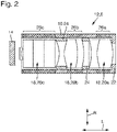
- optical assembly 12 shows in a simplified and schematic longitudinal sectional view an optical assembly 12 of an endoscope 2, for example an endoscope lens 6. This is arranged behind the protective disk 14 at the distal end 4 of the shaft 6 of the endoscope 2.
- the optical assembly 12 comprises an objective tube 16 and at least one optical element 18 held in the objective tube 16, for example three optical elements 18, namely a proximal one lens group 20a, a central lens group 20b and a distal lens group 20c.
- Lens groups 20a, 20b, 20c which are each composed of a plurality of individual lenses, are shown purely by way of example.
- An optical element is also an individual list, prism or the like.
- the optical elements 18 are held in the objective tube 16 by an end stop 22 at the proximal end of the objective tube 16 and by diaphragm tubes 24 which are present between the lens groups 20a, 20b, 20c and which also act as a stop.
- the optical elements 18 are held by at least one region 26a, 26b, 26c acting as a clamping mount for the optical elements 18.
- This area 26a, 26b, 26c of the objective tube 16, which acts as a clamping mount, is made at least in sections from a shape-memory material.
- a shape-memory alloy or a shape-memory polymer, for example, is provided as the shape-memory material.
- a shape memory alloy or a shape memory metal, such as Nitinol, is preferably used.
- the region 26a, 26b, 26c of the objective tube 16 that acts as a clamping mount completely encloses the optical element 18 along a circumference of the objective tube 16 .
- a first area 26a acting as a clamp mount a second area 26b acting as a clamp mount and a third area 26c acting as a clamp mount are provided.
- the regions 26a, 26b, 26c each have the shape of a hollow cylinder and completely enclose the associated optical element in one plane. This plane is perpendicular to the longitudinal axial direction L, which is oriented parallel to the optical axis of the optical system.
- the areas 26a, 26b, 26c of the objective tube 16 are preferably made entirely of a shape memory material.
- the objective tube 16 comprises a plurality of optical elements 18, namely the lens groups 20a, 20b, 20c.
- the first area 26a encloses the proximal lens group 20a as the first optical element 18, the second area 26b the central lens group 20b as the second optical element 18 and the third area 26c the distal lens group 20c as the third optical element 18.
- the between the proximal and the The central lens group 20b present in the distal lens group 20a, 20c is held alternatively via the anti-glare tubes 24.
- FIG. 2 shows the objective tube 16 in a deformed form, in which the objective tube 16 is circular in cross section.
- a subsequent temperature treatment above a memory temperature changes the objective tube 16, more precisely its areas 26a, 26b, 26c, into a trained shape.
- a trained form is to be understood as that form of the shape memory material into which it is brought at a correspondingly high temperature above the memory temperature.
- the deformed shape is the shape into which the material is brought by deformation below a critical temperature, so that this shape is not trained.
- the memory effect occurs from the deformed shape to the trained shape when the memory temperature is exceeded.
- the trained form of the objective tube 16 is chosen such that a clamp fit between the optical element 18 to be held and the area 26a, 26b, 26c of the objective tube acting as a clamping mount 16 is provided.
- the geometry and dimensions of the trained shape ensure that the optical elements 18 are held with an adequate, ie neither too high nor too low, clamping force.
- Deviating from the representation in 2 the objective tube 16 is also provided for accommodating optical elements 18 of different cross-sections, in particular optical elements 18 with different diameters.
- this requires that the regions 26a, 26b, 26c also have different cross sections, in particular different diameters, in the state in which they provide the clamping fit for the optical element 18 .
- the transition areas are deformable, for example plastically and/or elastically deformable.
- spring elements are provided as a deformable transition area.
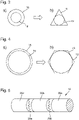
- FIG. 3 shows, in a schematically simplified cross-sectional view, an objective tube 16 in its deformed form ( Figure 3a ) and in its trained form ( Figure 3b ).
- the objective tube 16 more precisely its regions 26a, 26b, 26c, has a trained shape which, viewed in cross section of the objective tube 16, is triangular.
- the optical element 18 is inserted into the objective tube 16 in the deformed form.
- the areas 26a, 26b, 26c, preferably the entire objective tube 16 including the optical elements 18, are then brought to a temperature above the memory temperature of the shape-memory material used for the areas 26a, 26b, 26c.
- the shape memory material returns to its trained shape ( Figure 3b ).
- the wall of the objective tube 16 comes into contact with the optical element 18, so that a press fit for the optical element 18 is effected.
- the optical element 18 is held at three points along its circumference. A play-free and therefore particularly precise and secure seat of the optical element 18 in the objective tube 16 is thus brought about.
- the optical element 18 comes to rest along its circumference in each case in the middle of each side of the triangular objective tube 16 viewed in cross section.
- FIG. 4 shows another schematically simplified cross section through an objective tube 16 in its deformed form ( Figure 4a ) and in its trained form ( Figure 4b ).
- the objective tube 16 according to this exemplary embodiment is hexagonal when viewed in cross section. Again, the optical element 18 comes to rest centrally along its circumference on a respective side of this hexagon.
- a hexagonal cross-section has the advantage that, to adjust the position of the optical element 18, cross braces can be inserted into the objective tube 16, more precisely in its areas 26a, 26b, 26c, which can be removed again after the optical element 18 has been clamped in the objective tube 16 will.
- figure 5 1 shows, in a schematic, simplified and perspective cross-sectional view, an objective tube 16, comprising three areas 26a, 26b, 26c, between which there are two transition areas 28a, 28b.
- the first transition area 26a which is arranged between the first area 26a and the second area 26b, is a spring element. These are able to deform elastically and thus to compensate for different cross sections of the first and second areas 26a, 26b, in particular different diameters of these areas 26a, 26b.
- the procedure for producing an optical assembly 12, for example an endoscope lens 6, is as follows: First, an lens tube 16 is provided, which comprises at least one area 26a, 26b, 26c acting as a clamping mount for the optical element 18.
- This region 26a, 26b, 26c is made, at least in sections, from a shape-memory material, for example a shape-memory metal such as nitinol.
- the area 26a, 26b, 26c is made entirely of a shape memory material.
- At least one optical element 18, for example a lens group 20a, 20b, 20c, in particular a plurality of optical elements 18, for example the three lens groups 20a, 20b, 20c, is then inserted into the objective tube 16.
- the optical element or elements 18 can be accommodated exactly in the objective tube 16 with the aid of the objective tube 16 according to aspects of the invention, which is produced in particular using a shape memory material.
- a shape memory material is produced in particular using a shape memory material.
- the optical elements 18 can be accommodated in the objective tube 16 with such precision that high optical requirements for the adjustment of the optical system are met.
- the provided optical unit 12 for example the endoscope lens 6, for capturing high-resolution image information (HD, ultra HD, 4K and higher).
Description
Die Erfindung betrifft eine optische Baueinheit eines Endoskops umfassend ein Objektivrohr und zumindest ein in dem Objektivrohr gehaltenes optisches Element. Ferner betrifft die Erfindung ein Endoskop umfassend eine optische Baueinheit, ein Verfahren zum Herstellen einer optischen Baueinheit sowie die Verwendung eines Formgedächtnismaterials.The invention relates to an optical assembly of an endoscope comprising an objective tube and at least one optical element held in the objective tube. Furthermore, the invention relates to an endoscope comprising an optical assembly, a method for producing an optical assembly and the use of a shape memory material.
Mit einem Endoskopobjektiv wird ein Untersuchungsgebiet vor einem distalen Ende des Endoskopschafts beobachtet. Gegenüber dem Außenraum ist das Endoskopobjektiv typischerweise mit einem Schutzfenster abgedichtet. Das Endoskopobjektiv bildet das Untersuchungsgebiet auf einen Bildsensor ab. Alternativ wird das Bild über Relaisoptiken bis in den proximalen Bereich des Endoskops projiziert. Dort befindet sich der Bildsensor oder ein Okular zur direkten Beobachtung des Untersuchungsgebiets. Bei flexiblen Endoskopen erfolgt die optische Abbildung auf ein flexibles Bündel optischer Fasern.An examination area in front of a distal end of the endoscope shaft is observed with an endoscope lens. The endoscope lens is typically sealed off from the outside with a protective window. The endoscope lens maps the examination area onto an image sensor. Alternatively, the image is projected into the proximal area of the endoscope via relay optics. This is where the image sensor or an eyepiece is located for direct observation of the examination area. With flexible endoscopes, the optical imaging takes place on a flexible bundle of optical fibers.
Das Endoskopobjektiv und die Relaisoptiken werden nachfolgend allgemein als optische Baueinheiten des Endoskops bezeichnet. Sie umfassen üblicherweise mehrere Linsen oder Linsengruppen, die in Längsrichtung des Endoskops hintereinander angeordnet und in einem Objektiv- oder Systemrohr gehalten sind.The endoscope lens and the relay optics are generally referred to below as optical components of the endoscope. They usually include several lenses or lens groups, which are arranged one behind the other in the longitudinal direction of the endoscope and are held in an objective or system tube.
Aus
Ferner ist aus der
Aus
Aus
Es ist eine Aufgabe der Erfindung, eine optische Baueinheit eines Endoskops, ein Endoskop umfassend eine optische Baueinheit, ein Verfahren zum Herstellen einer optischen Baueinheit sowie die Verwendung eines Formgedächtnismaterials anzugeben, wobei die optische Baueinheit effizienter herstellbar ist und gleichzeitig hohen optischen Anforderungen genügt.It is an object of the invention to specify an optical assembly of an endoscope, an endoscope comprising an optical assembly, a method for producing an optical assembly and the use of a shape memory material, wherein the optical assembly can be produced more efficiently and at the same time meets high optical requirements.
Die Aufgabe wird gelöst durch eine optische Baueinheit eines Endoskops umfassend ein Objektivrohr und zumindest ein in dem Objektivrohr gehaltenes optisches Element, wobei die optische Baueinheit dadurch fortgebildet ist, dass das Objektivrohr zumindest einen als Klemmfassung für das optische Element wirkenden Bereich umfasst, wobei dieser als Klemmfassung wirkende Bereich des Objektivrohrs zumindest abschnittsweise aus einem Formgedächtnismaterial hergestellt ist, wobei ein Memory-Effekt des Formgedächtnismaterials von einer verformten Form in eine trainierte Form bei Überschreiten einer Memory-Temperatur eintritt und die trainierte Form des Objektivrohrs so gewählt ist, dass ein Klemmsitz zwischen dem zu haltenden optischen Element und dem als Klemmfassung wirkenden Bereich des Objektivrohrs bereitgestellt wird, wobei zumindest ein erstes optisches Element und ein zweites optisches Element vorhanden sind, wobei das erste optische Element in einem als Klemmfassung für das erste optische Element wirkenden ersten Bereich des Objektivrohrs und das zweite optische Element in einem als Klemmfassung für das zweite optische Element wirkenden zweiten Bereich des Objektivrohrs gehalten sind, und wobei das Objektivrohr zwischen dem ersten Bereich und dem zweiten Bereich einen verformbaren Übergangsbereich umfasst, der leichter verformbar als die sich benachbart anschließenden ersten und zweiten Bereiche des Objektivrohrs ist, und wobei der erste Bereich einen ersten Querschnitt und der zweite Bereich einen davon verschiedenen zweiten Querschnitt aufweist, wobei der erste und der zweite Querschnitt unterschiedlich in Größe oder Form sind und wobei der verformbare Übergangsbereich einen Übergang vom ersten Querschnitt auf den zweiten Querschnitt zwischen dem ersten und dem zweiten Bereich schafft, wobei als Übergangsbereich zumindest ein Federelement vorhanden ist.The object is achieved by an optical assembly of an endoscope comprising an objective tube and at least one optical element held in the objective tube, the optical assembly being developed in that the objective tube comprises at least one area that acts as a clamp mount for the optical element, this region acting as a clamp mount effective area of the lens tube is made at least in sections from a shape memory material, with a memory effect of the shape memory material occurring from a deformed shape to a trained shape when a memory temperature is exceeded and the trained shape of the lens tube is selected such that a press fit between the holding optical element and acting as a clamp mount area of the lens tube is provided, with at least a first optical element and a second optical element being present, the first optical element in a clamp mount for the first optisc The first area of the objective tube that acts on the element and the second optical element are held in a second area of the objective tube that acts as a clamping mount for the second optical element, and wherein the objective tube comprises a deformable transition area between the first area and the second area, which is more easily deformable than the adjacent first and second portions of the objective tube, and wherein the first portion has a first cross-section and the second portion has a different second cross-section, the first and second cross-sections being different in size or shape, and wherein the deformable transition portion creates a transition from the first cross section to the second cross section between the first and the second area, with at least one spring element being present as the transition area.
Unter einem Objektivrohr wird im Kontext der vorliegenden Beschreibung stets auch ein Systemrohr verstanden.In the context of the present description, an objective tube is always also understood to mean a system tube.
Die Erfindung beruht auf der folgenden Erkenntnis: Die Toleranzen der Einzelkomponenten bei der Herstellung optischer Baueinheiten, beispielsweise Endoskopobjektiven oder Relaisoptiken, stößt an die Grenze des technisch Machbaren und ist immer noch zu groß, um die steigenden optischen Anforderungen, vor allem im Hinblick auf hochauflösende Bilderfassung (HD, 4K und nachfolgende Technologien), zu erfüllen. Ein Presssitz des optischen Elements in dem als Klemmfassung für das optische Element wirkenden Bereich des Objektivrohrs führt - was erfindungsgemäß erkannt wurde - zur Möglichkeit, diese Forderungen auf mechanischer Seite im Hinblick auf Toleranzen, Fertigungsgenauigkeit und Justagepräzision der optischen Elemente zu erfüllen. Die optischen Elemente, beispielsweise Linsen oder Linsengruppen, werden mit hoher Präzision auf der optischen Achse des optischen Systems zentriert. Dieser Effekt tritt ein, da das Formgedächtnismaterial in der Lage ist, einen gleichmäßig von allen Seiten wirkenden Anpressdruck auf das optische Element auszuüben.The invention is based on the following finding: The tolerances of the individual components in the production of optical assemblies, for example endoscope lenses or relay optics, are reaching the limits of what is technically feasible and are still too large to meet the increasing optical requirements, especially with regard to high-resolution image acquisition (HD, 4K and subsequent technologies). A press fit of the optical element in the region of the objective tube acting as a clamping mount for the optical element leads—as has been recognized according to the invention—to the possibility of meeting these requirements on the mechanical side in terms of tolerances, manufacturing accuracy and adjustment precision of the optical elements. The optical elements, such as lenses or lens groups, are centered on the optical axis of the optical system with great precision. This effect occurs because the shape-memory material is able to exert a contact pressure that acts uniformly from all sides on the optical element.
Gemäß einer vorteilhaften Ausführungsform ist die optische Baueinheit dadurch fortgebildet, dass der als Klemmfassung wirkende Bereich des Objektivrohrs das optische Element entlang eines Umfangs des Objektivrohrs vollständig umschließt und ferner vollständig aus dem Formgedächtnismaterial hergestellt ist.According to an advantageous embodiment, the optical assembly developed in that the area of the objective tube that acts as a clamping mount completely encloses the optical element along a circumference of the objective tube and is also made entirely of the shape-memory material.
Der Umfang des Objektivrohrs wird in einer Ebene senkrecht zur optischen Achse des optischen Systems bzw. senkrecht zur Mittenlängsachse des Objektivrohrs betrachtet.The circumference of the objective tube is viewed in a plane perpendicular to the optical axis of the optical system or perpendicular to the central longitudinal axis of the objective tube.
Eine vollflächige Anlage des optischen Elements entlang seines Umfangs an dem Objektivrohr ist nicht zwangsläufig vorgesehen. Es ist vorteilhaft, wenn das optische Element definiert an einzelnen Punkten, welche insbesondere gleichmäßig entlang des Umfangs des optischen Elements verteilt sind, in dem als Klemmfassung wirkenden Bereich des Objektivrohrs gehalten wird. Diese Art der Klemmhalterung erlaubt eine spielfreie, präzise und definierte Aufnahme des optischen Elements in der durch das Objektivrohr bereitgestellten Klemmhalterung.A full-surface contact of the optical element along its circumference with the objective tube is not necessarily provided. It is advantageous if the optical element is held in a defined manner at individual points, which are in particular distributed uniformly along the circumference of the optical element, in the area of the objective tube that acts as a clamping mount. This type of clamp mount allows the optical element to be accommodated without play, precisely and in a defined manner in the clamp mount provided by the objective tube.
Zumindest ein erstes optisches Element und ein zweites optisches Element sind vorhanden, wobei das erste optische Element in einem als Klemmfassung für das erste optische Element wirkenden ersten Bereich des Objektivrohrs und das zweite optische Element in einem als Klemmfassung für das zweite optische Element wirkenden zweiten Bereich des Objektivrohrs gehalten sind, und wobei das Objektivrohr zwischen dem ersten Bereich und dem zweiten Bereich einen verformbaren Übergangsbereich umfasst.At least a first optical element and a second optical element are present, the first optical element being in a first area of the objective tube that acts as a clamp mount for the first optical element, and the second optical element in a second area of the objective tube that acts as a clamp mount for the second optical element Objective tube are held, and wherein the objective tube comprises a deformable transition region between the first region and the second region.
Im Kontext der vorliegenden Beschreibung bedeutet "verformbarer Übergangsbereich", dass dieser Übergangsbereich plastisch oder elastisch leichter verformbar bzw. mechanisch weicher ist als die benachbart anschließenden Bereiche bzw. Abschnitte des Objektivrohrs. Als Übergangsbereich sind erfindungsgemäss Federelemente vorgesehen. Ferner ist es möglich, den Übergangsbereich aus einem Metall oder aus Kunststoff herzustellen.In the context of the present description, “deformable transition area” means that this transition area is easier to deform plastically or elastically or is mechanically softer than the adjacent adjoining areas or sections of the lens tube. According to the invention, spring elements are provided as the transition area. Furthermore, it is possible to produce the transition area from a metal or from plastic.
Vorteilhaft wird die Möglichkeit geschaffen, unterschiedlich große und unterschiedlich geformte optische Elemente spielfrei, fest und sicher in dem Objektivrohr aufzunehmen. Das Formgedächtnismaterial ist lokal, d.h. in jedem einzelnen Bereich, in der Lage, sich optimal an das dort aufgenommene bzw. gehaltene optische Element anzuschmiegen und dieses sicher zu halten.The possibility is advantageously created of accommodating optical elements of different sizes and shapes without play, firmly and securely in the objective tube. The shape memory material is locally, i.e. in each individual area, able to optimally nestle against the optical element received or held there and to hold it securely.
Es ist vorgesehen, dass der erste Bereich einen ersten Querschnitt und der zweite Bereich einen davon verschiedenen zweiten Querschnitt aufweist, wobei der erste und der zweite Querschnitt unterschiedlich in Größe oder Form sind, und wobei der verformbare Übergangsbereich einen Übergang vom ersten Querschnitt auf den zweiten Querschnittzwischen dem ersten und dem zweiten Bereich, schafft.It is contemplated that the first portion has a first cross-section and the second portion has a different second cross-section, the first and second cross-sections being different in size or shape, and the deformable transition portion having a transition from the first cross-section to the second cross-section between the first and the second area.
Unterschiedliche Formen der optischen Elemente, welche einen unterschiedlichen Querschnitt, sei es in Größe oder Form, erfordern, lassen sich in der optischen Baueinheit gemäß der genannten Ausführungsform aufnehmen. Gleiches gilt beispielsweise für verschieden große Linsen, welche unterschiedlich große Durchmesser aufweisen. Insbesondere sind die einzelnen Bereiche des Objektivrohrs so zueinander angeordnet, dass die in ihnen aufgenommenen optischen Elemente präzise auf einer gemeinsamen optischen Achse gehalten werden. Es ist ferner vorgesehen, dass in unterschiedlichen Bereichen unterschiedliche Klemmkräfte auf die dort gehaltenen optischen Elemente ausgeübt werden.Different shapes of the optical elements, which require a different cross-section, be it in size or shape, can be accommodated in the optical assembly according to the embodiment mentioned. The same applies, for example, to lenses of different sizes, which have diameters of different sizes. In particular, the individual areas of the objective tube are arranged relative to one another in such a way that the optical elements accommodated in them are held precisely on a common optical axis. Provision is also made for different clamping forces to be exerted on the optical elements held there in different areas.
Gemäß einer weiteren Ausführungsform ist vorgesehen, dass der als Klemmfassung wirkende zumindest eine Bereich des Objektivrohrs eine trainierte Form hat, die im Querschnitt des Objektivrohrs betrachtet polygonförmig ist, wobei insbesondere eine verformte Form des Objektivrohrs zumindest in dem als Klemmfassung wirkenden Bereich kreisrund ist.According to a further embodiment, it is provided that the at least one area of the objective tube acting as a clamping mount has a trained shape which, viewed in cross-section of the objective tube, is polygonal, with a deformed shape of the objective tube being circular at least in the area acting as a clamping mount.
Im Kontext der vorliegenden Beschreibung ist eine "trainierte Form" diejenige Form des Formgedächtnismaterials, an die es sich "erinnert", wenn es auf eine Temperatur oberhalb der Memory-Temperatur erwärmt wird. Als "verformte Form" wird diejenige Form bezeichnet, in die das Material durch Verformung unterhalb einer kritischen Temperatur gebracht wurde, so dass kein Trainieren dieser Form stattfindet. Der Formgedächtniseffekt oder Memory-Effekt tritt also von der verformten Form in die trainierte Form ein, wenn die Memory-Temperatur überschritten wird.In the context of the present specification, a "trained shape" is that shape of the shape memory material that it "remembers" when heated to a temperature above the memory temperature. The "deformed shape" refers to the shape into which the material was brought by deformation below a critical temperature, so that this shape is not trained. The shape memory effect or memory effect thus occurs from the deformed shape to the trained shape when the memory temperature is exceeded.
Die trainierte Form ist insbesondere so gewählt, dass ein Klemmsitz zwischen dem optischen Element und dem als Klemmfassung wirkenden Bereich des Objektivrohrs bereitgestellt wird. Die trainierte Form wird also mit anderen Worten so gewählt, dass eine erzeugte Klemmkraft für das aufzunehmende optische Element weder zu hoch noch zu gering ist.The trained shape is selected in particular in such a way that a clamping fit is provided between the optical element and the area of the objective tube that acts as a clamping mount. In other words, the trained form is selected in such a way that a generated clamping force for the optical element to be accommodated is neither too high nor too low.
Bevorzugt kommt das optische Element jeweils in der Mitte einer Seite der genannten Vielecke zur Anlage. Eine Dreiecksform des Objektivrohrs, zumindest in dem als Klemmfassung für das optische Element wirkenden Bereich, ist besonders vorteilhaft, da eine Dreipunktaufnahme die, geometrisch gesehen, stabilste Aufnahme des optischen Elements darstellt. Ein sechseckiges Profil hat den Vorteil, dass zur Justage auf der optischen Achse Querstreben eingesetzt werden können, die nach erfolgtem Klemmvorgang wieder entfernt werden.The optical element preferably comes to rest in the middle of one side of the said polygons. A triangular shape of the objective tube, at least in the area acting as a clamping mount for the optical element, is particularly advantageous, since a three-point mount represents the most stable mount of the optical element from a geometric point of view. A hexagonal profile has the advantage that cross braces can be used for adjustment on the optical axis, which are removed again after the clamping process has taken place.
Gemäß einer weiteren Ausführungsform ist die optische Baueinheit dadurch fortgebildet, dass das Formgedächtnismaterial eine Formgedächtnislegierung und/oder ein Formgedächtnispolymer ist.According to a further embodiment, the optical assembly is developed in that the shape memory material is a shape memory alloy and/or a shape memory polymer.
Eine Formgedächtnislegierung oder ein Memory-Metall ist vielfach eine Nickel-Titan-Legierung, beispielsweise ein unter dem Namen "Nitinol" bekanntes Material.A shape memory alloy or a memory metal is often a nickel-titanium alloy, for example a material known by the name "nitinol".
Bei dem optischen Element handelt es sich insbesondere um eine Linse. Ferner handelt es sich bevorzugt um miteinander verklebte Linsen, die eine Linsengruppe bilden. Die optischen Elemente der optischen Baueinheit werden ferner bevorzugt ohne weitere Haltemaßnahmen, wie beispielsweise eine Verklebung, Verschraubung oder dgl., in dem Objektivrohr gehalten. Die oben genannten Aspekte betreffen vorteilhaft alle Ausführungsformen.The optical element is in particular a lens. Furthermore, the lenses are preferably glued together and form a lens group. The optical elements of the optical assembly are also preferably held in the objective tube without further holding measures, such as gluing, screwing or the like. The aspects mentioned above advantageously relate to all embodiments.
Die Aufgabe wird ferner gelöst durch ein Endoskop umfassend eine optische Baueinheit nach einem oder mehreren der genannten Ausführungsformen als Endoskopobjektiv oder Relaisoptik, wobei insbesondere das optische Element eine Linse oder eine Linsengruppe ist.The object is also achieved by an endoscope comprising an optical assembly according to one or more of the specified embodiments as an endoscope lens or relay optics, with the optical element in particular being a lens or a lens group.
Das Endoskopobjektiv gemäß Aspekten der Erfindung ist für die hochauflösende Bilderfassung geeignet, da im Hinblick auf Toleranzen der Einzelkomponenten der optischen Baueinheit die vorhandenen technischen Beschränkungen vorteilhaft überwunden werden.The endoscope lens according to aspects of the invention is for suitable high-resolution image acquisition, since the existing technical limitations are advantageously overcome with regard to tolerances of the individual components of the optical assembly.
Ferner wird die Aufgabe gelöst durch ein Verfahren zum Herstellen einer optischen Baueinheit nach einem oder mehreren der genannten Ausführungsformen, wobei das Verfahren durch die folgenden Schritte fortgebildet ist:
- Bereitstellen eines Objektivrohrs, welches zumindest einen als Klemmfassung für das optische Element wirkenden Bereich umfasst, der zumindest abschnittsweise aus einem Formgedächtnismaterial hergestellt ist,
- Einsetzen zumindest eines optischen Elements in den als Klemmfassung wirkenden Bereich des Objektivrohrs,
- Erwärmen des zumindest einen als Klemmfassung wirkenden Bereich des Objektivrohrs auf eine Temperatur oberhalb der Memory-Temperatur des verwendeten Formgedächtnismaterials.
- Providing an objective tube, which comprises at least one area that acts as a clamping mount for the optical element and is made at least in sections from a shape memory material,
- Insertion of at least one optical element in the area of the objective tube that acts as a clamp mount,
- Heating the at least one area of the objective tube acting as a clamping mount to a temperature above the memory temperature of the shape memory material used.
Ferner wird die Aufgabe gelöst durch die Verwendung eines Formgedächtnismaterials zum Herstellen eines Objektivrohrs einer optischen Baueinheit nach einem oder mehreren der genannten Ausführungsformen. Insbesondere wird ein Formgedächtnismetall oder eine Formgedächtnislegierung, bevorzugt Nitinol, verwendet.Furthermore, the object is achieved through the use of a shape-memory material for producing an objective tube of an optical assembly according to one or more of the specified embodiments. In particular, a shape memory metal or alloy, preferably nitinol, is used.
Auf das Verfahren und die Verwendung treffen gleiche oder ähnliche Vorteile zu, wie bereits im Hinblick auf die optische Baueinheit eines Endoskops erwähnt wurden, weshalb auf eine erneute Nennung verzichtet wird.The same or similar advantages apply to the method and the use as have already been mentioned with regard to the optical structural unit of an endoscope, which is why it is not mentioned again.
Weitere Merkmale der Erfindung werden aus der Beschreibung erfindungsgemäßer Ausführungsformen zusammen mit den Ansprüchen und den beigefügten Zeichnungen ersichtlich. Erfindungsgemäße Ausführungsformen können einzelne Merkmale oder eine Kombination mehrerer Merkmale erfüllen.Further features of the invention will become apparent from the description of the invention Embodiments can be seen together with the claims and the accompanying drawings. Embodiments according to the invention can fulfill individual features or a combination of several features.
Die Erfindung wird nachstehend ohne Beschränkung des allgemeinen Erfindungsgedankens anhand von Ausführungsbeispielen unter Bezugnahme auf die Zeichnungen beschrieben, wobei bezüglich aller im Text nicht näher erläuterten erfindungsgemäßen Einzelheiten ausdrücklich auf die Zeichnungen verwiesen wird. Es zeigen:
- Fig. 1
- ein Endoskop in schematischer, vereinfachter und perspektivischer Ansicht,
- Fig. 2
- eine optische Baueinheit eines Endoskops in einem schematisch vereinfachten Längsschnitt,
- Fig. 3a, 3b und 4a, 4b
- schematisch vereinfachte Querschnittsansichten durch ein Objektivrohr in verformter Form und in trainierter Form und
- Fig. 5
- eine schematisch vereinfachte und perspektivische Ansicht eines Objektivrohrs.
- 1
- an endoscope in a schematic, simplified and perspective view,
- 2
- an optical assembly of an endoscope in a schematically simplified longitudinal section,
- Figures 3a, 3b and 4a, 4b
- schematically simplified cross-sectional views through an objective tube in deformed form and in trained form and
- figure 5
- a schematically simplified and perspective view of an objective tube.
In den Zeichnungen sind jeweils gleiche oder gleichartige Elemente und/oder Teile mit denselben Bezugsziffern versehen, so dass von einer erneuten Vorstellung jeweils abgesehen wird.In the drawings, elements and/or parts that are the same or of the same type are provided with the same reference numbers, so that they are not presented again in each case.
Die optischen Elemente 18 sind in dem Objektivrohr 16 durch einen Endanschlag 22 am proximalen Ende des Objektivrohrs 16 sowie durch zwischen den Linsengruppen 20a, 20b, 20c vorhandene Blendrohre 24, die ebenfalls als Anschlag wirken, gehalten. In radialer Richtung R, die senkrecht zu der Längsaxialrichtung L der optischen Baueinheit 12 verläuft, sind die optischen Elemente 18 durch zumindest einen als Klemmfassung für die optischen Elemente 18 wirkenden Bereich 26a, 26b, 26c gehalten.The
Dieser als Klemmfassung wirkende Bereich 26a, 26b, 26c des Objektivrohrs 16 ist zumindest abschnittsweise aus einem Formgedächtnismaterial hergestellt. Als Formgedächtnismaterial ist beispielsweise eine Formgedächtnislegierung oder ein Formgedächtnispolymer vorgesehen. Bevorzugt kommt eine Formgedächtnislegierung oder ein Formgedächtnismetall, wie beispielsweise Nitinol, zum Einsatz.This
Der als Klemmfassung wirkende Bereich 26a, 26b, 26c des Objektivrohrs 16 umschließt das optische Element 18 entlang eines Umfangs des Objektivrohrs 16 vollständig. Im dargestellten Ausführungsbeispiel sind ein erster als Klemmfassung wirkender Bereich 26a, ein zweiter als Klemmfassung wirkender Bereich 26b und ein dritter als Klemmfassung wirkender Bereich 26c vorgesehen. Die Bereiche 26a, 26b, 26c haben jeweils die Form eines Hohlzylinders und umschließen das zugehörige optische Element in einer Ebene vollständig. Diese Ebene liegt senkrecht zur Längsaxialrichtung L, welche parallel zur optischen Achse des optischen Systems orientiert ist. Die Bereiche 26a, 26b, 26c des Objektivrohrs 16 sind bevorzugt vollständig aus einem Formgedächtnismaterial hergestellt.The
Im dargestellten Ausführungsbeispiel umfasst das Objektivrohr 16 mehrere optische Elemente 18, nämlich die Linsengruppen 20a, 20b, 20c. Beispielhaft umschließt der erste Bereich 26a die proximale Linsengruppe 20a als erstes optisches Element 18, der zweite Bereich 26b die zentrale Linsengruppe 20b als zweites optisches Element 18 und der dritte Bereich 26c die distale Linsengruppe 20c als drittes optisches Element 18. Die zwischen der proximalen und der distalen Linsengruppe 20a, 20c vorhandene zentrale Linsengruppe 20b ist alternativ über die Blendrohre 24 gehalten.In the exemplary embodiment shown, the
Im Kontext der vorliegenden Beschreibung ist unter einer trainierten Form diejenige Form des Formgedächtnismaterials zu verstehen, in die es bei einer entsprechend hohen Temperatur oberhalb der Memory-Temperatur gebracht wird. Als verformte Form wird die Form bezeichnet, in die das Material durch Verformung unterhalb einer kritischen Temperatur gebracht wird, so dass kein Trainieren dieser Form stattfindet. Der Memory-Effekt tritt von der verformten Form in die trainierte Form bei Überschreiten der Memory-Temperatur ein.In the context of the present description, a trained form is to be understood as that form of the shape memory material into which it is brought at a correspondingly high temperature above the memory temperature. The deformed shape is the shape into which the material is brought by deformation below a critical temperature, so that this shape is not trained. The memory effect occurs from the deformed shape to the trained shape when the memory temperature is exceeded.
Die trainierte Form des Objektivrohrs 16 ist so gewählt, dass ein Klemmsitz zwischen dem zu haltenden optischen Element 18 und dem als Klemmfassung wirkenden Bereich 26a, 26b, 26c des Objektivrohrs 16 bereitgestellt wird. Die Geometrie und Abmessungen der trainierten Form stellen sicher, dass die optischen Elemente 18 mit einer adäquaten, also weder zu hohen noch zu geringen, Klemmkraft gehalten werden.The trained form of the
Abweichend von der Darstellung in
In der verformten Form wird das optische Element 18 in das Objektivrohr 16 eingesetzt. Anschließend werden die Bereiche 26a, 26b, 26c bevorzugt das gesamte Objektivrohr 16 einschließlich der optischen Elemente 18, auf eine Temperatur oberhalb der Memory-Temperatur des für die Bereiche 26a, 26b, 26c verwendeten Formgedächtnismaterials gebracht. Das Formgedächtnismaterial kehrt in seine trainierte Form zurück (
Zum Herstellen einer optischen Baueinheit 12, beispielsweise eines Endoskopobjektivs 6, wird gemäß einem Ausführungsbeispiel wie folgt verfahren: Zunächst wird ein Objektivrohr 16 bereitgestellt, welches zumindest einen als Klemmfassung für das optische Element 18 wirkenden Bereich 26a, 26b, 26c umfasst. Dieser Bereich 26a, 26b, 26c ist, zumindest abschnittsweise, aus einem Formgedächtnismaterial, beispielsweise einem Formgedächtnismetall wie Nitinol, hergestellt. Insbesondere ist der Bereich 26a, 26b, 26c vollständig aus einem Formgedächtnismaterial hergestellt. Anschließend wird zumindest ein optisches Element 18, beispielsweise eine Linsengruppe 20a, 20b, 20c, insbesondere mehrere optische Elemente 18, wie beispielsweise die drei Linsengruppen 20a, 20b, 20c, in das Objektivrohr 16 eingesetzt. Durch anschließendes Erwärmen zumindest der Bereiche 26a, 26b, 26c, insbesondere des gesamten Objektivrohrs 16, einschließlich der eingesetzten optischen Elemente 18, auf eine Temperatur oberhalb der Memory-Temperatur des verwendeten Formgedächtnismaterials, wird ein Klemmsitz zwischen dem als Klemmfassung wirkenden Bereich 26a, 26b, 26c und dem optischen Element 18 hergestellt.According to one exemplary embodiment, the procedure for producing an optical assembly 12, for example an
Mithilfe des Objektivrohrs 16 gemäß Aspekten der Erfindung, welches insbesondere unter Verwendung eines Formgedächtnismaterials hergestellt ist, sind das oder die optischen Elemente 18 exakt in dem Objektivrohr 16 aufnehmbar. Vorteilhaft entfällt die Notwendigkeit, weitere Maßnahmen zum Fixieren der optischen Elemente 18, wie beispielsweise Klebstoff, vorzusehen. Die optischen Elemente 18 sind derart genau in dem Objektivrohr 16 aufnehmbar, das hohe optische Anforderungen an die Justage des optischen Systems erfüllt werden. Insbesondere ist die bereitgestellte optische Einheit 12, beispielsweise das Endoskopobjektiv 6, zur Erfassung hoch auflösender Bildinformationen (HD, ultra HD, 4K und höher) geeignet.The optical element or
- 22
- Endoskopendoscope
- 44
- distales Endedistal end
- 66
- Endoskopobjektivendoscope lens
- 88th
- Schaftshaft
- 1010
- Handgriffhandle
- 1212
- optische Baueinheitoptical assembly
- 1414
- Schutzscheibeprotective screen
- 1616
- Objektivrohrlens tube
- 1818
- optisches Elementoptical element
- 20a20a
- proximale Linsengruppeproximal lens group
- 20b20b
- zentrale Linsengruppecentral lens group
- 20c20c
- distale Linsengruppedistal lens group
- 2222
- Endanschlagend stop
- 2424
- Blendrohrbaffle tube
- 26a26a
- erster Bereichfirst area
- 26b26b
- zweiter Bereichsecond area
- 26c26c
- dritter Bereichthird area
- 28a28a
- erster Übergangsbereichfirst transition area
- 28b28b
- zweiter Übergangsbereichsecond transition area
- RR
- radiale Richtungradial direction
- LL
- Längsaxialrichtunglongitudinal axial direction
Claims (7)
- An optical assembly (12) of an endoscope (2) comprising an objective tube (16) and at least one optical element (18) held in the objective tube (16), wherein the objective tube (16) comprises at least one region (26a, 26b, 26c) functioning as a clamping mount for the optical element (18), wherein this region (26a, 26b, 26c) of the objective tube (16) functioning as a clamping mount is manufactured at least sectionally from a shape-memory material, wherein a memory effect of the shape-memory material from a deformed shape to a trained shape occurs when a memory temperature is exceeded and the trained shape of the objective tube (16) is selected in that there is a clamping mount between the optical element (18) to be held and the region (26a, 26b, 26c) of the objective tube (16) functioning as a clamping mount, wherein at least one first optical element (18, 20a) and one second optical element (18, 20b) are available, wherein the first optical element (18, 20a) is held in a first region (26a) of the objective tube (16) functioning as a clamping mount for the first optical element (18, 20a) and the second optical element (18, 20b) is held in a second region (20b) of the objective tube (16) functioning as a clamping mount for the second optical element (18, 20b), wherein the objective tube (16) comprises a deformable transition region (28a, 28b) between the first region (26a) and the second region (26b), which is easier deformable than the neighboring adjacent first and second regions (26a, 26b) of the objective tube (16) and wherein the first region (26a) has a first cross-section and the second region (26b) has a second cross-section different therefrom, wherein the first and the second cross-section are different in size and shape and wherein the deformable transition region (28a, 28b) creates a transition from the first cross-section to the second cross-section between the first and second region (26a, 26b) and wherein at least one spring element is provided as the transition region (28a, 28b).
- The optical assembly (12) according to claim 1, characterized in that the region (26a, 26b, 26c) of the objective tube (16) acting as a clamping mount fully encloses the optical element (18) along a circumference of the objective tube (16) and moreover is made completely from the shape-memory material.
- The optical assembly (12) according to claim 1 or 2, characterized in that the at least one region (26a, 26b, 26c) of the objective tube (16) functioning as the clamping mount has a trained shape which is polygonal viewed in the cross-section of the objective tube (16), wherein a deformed shape of the objective tube (16) is circular, at least in the region (26a, 26b, 26c) functioning as the clamping mount.
- The optical assembly (12) according to one of claims 1 to 3 characterized in that the shape-memory material is a shape-memory alloy and/or a shape-memory polymer.
- An endoscope (2) comprising an optical assembly (12) according to one of claims 1 to 4 as an endoscope objective (6) or relay lens.
- A method for producing an optical assembly (12) according to one of claims 1 to 5, characterized by the following steps:- Providing an objective tube (16) that at least comprises a region (26a, 26b, 26c) which functions as a clamping mount for the optical element (18) and is at least sectionally manufactured from a shape-memory material,- Inserting at least one optical element (18) into the region (26a, 26b, 26c) of the objective tube (16) functioning as a clamping mount,- Heating the at least one region (26a, 26b, 26c) of the objective tube (16) functioning as a clamping mount to a temperature above the memory temperature of the used shape-memory material.
- A use of a shape-memory material for manufacturing an objective tube (16) of an optical assembly (12) according to one of claims 1 to 4 of an endoscope (2) according to claim 5.
Applications Claiming Priority (2)
| Application Number | Priority Date | Filing Date | Title |
|---|---|---|---|
| DE102015203357.0A DE102015203357A1 (en) | 2015-02-25 | 2015-02-25 | Optical assembly of an endoscope |
| PCT/EP2016/052060 WO2016134919A1 (en) | 2015-02-25 | 2016-02-01 | Assembly of an endoscope having a tube comprising shape-memory material for the clamp-mounting of optical elements |
Publications (2)
| Publication Number | Publication Date |
|---|---|
| EP3262456A1 EP3262456A1 (en) | 2018-01-03 |
| EP3262456B1 true EP3262456B1 (en) | 2022-09-28 |
Family
ID=55299455
Family Applications (1)
| Application Number | Title | Priority Date | Filing Date |
|---|---|---|---|
| EP16702699.6A Active EP3262456B1 (en) | 2015-02-25 | 2016-02-01 | Assembly of an endoscope having a tube comprising shape-memory material for the clamp-mounting of optical elements |
Country Status (5)
| Country | Link |
|---|---|
| US (1) | US10401613B2 (en) |
| EP (1) | EP3262456B1 (en) |
| JP (2) | JP2018506386A (en) |
| DE (1) | DE102015203357A1 (en) |
| WO (1) | WO2016134919A1 (en) |
Families Citing this family (4)
| Publication number | Priority date | Publication date | Assignee | Title |
|---|---|---|---|---|
| USD841160S1 (en) * | 2016-04-01 | 2019-02-19 | Deka Products Limited Partnership | Endoscope |
| DE102017116652A1 (en) * | 2017-07-24 | 2019-01-24 | Olympus Winter & Ibe Gmbh | Imaging unit for a surgical instrument and method for making an imaging unit |
| DE102017123896A1 (en) * | 2017-10-13 | 2019-04-18 | Olympus Winter & Ibe Gmbh | Optical system for a stereo video endoscope |
| US11291470B2 (en) * | 2017-12-12 | 2022-04-05 | Alcon Inc. | Surgical probe with shape-memory material |
Citations (2)
| Publication number | Priority date | Publication date | Assignee | Title |
|---|---|---|---|---|
| JPS63208018A (en) * | 1987-02-25 | 1988-08-29 | Mitsubishi Cable Ind Ltd | Fiber scope |
| US5607435A (en) * | 1994-05-23 | 1997-03-04 | Memory Medical Systems, Inc. | Instrument for endoscopic-type procedures |
Family Cites Families (6)
| Publication number | Priority date | Publication date | Assignee | Title |
|---|---|---|---|---|
| DE3007307A1 (en) * | 1980-01-18 | 1981-07-23 | BBC AG Brown, Boveri & Cie., Baden, Aargau | Detachable shrunk joint - uses shape memory alloy with two=way effect |
| JP3210404B2 (en) * | 1992-04-15 | 2001-09-17 | 株式会社町田製作所 | Optical fiber binding device |
| DE19732991C2 (en) | 1997-07-31 | 1999-09-09 | Storz Karl Gmbh & Co | Endoscope and method for mounting components of an optical system |
| JP2006133695A (en) * | 2004-11-09 | 2006-05-25 | Alps Electric Co Ltd | Lens mount structure |
| DE102008038619B3 (en) | 2008-08-12 | 2010-02-11 | Olympus Winter & Ibe Gmbh | Endoscope e.g. video endoscope, lens for e.g. providing image on sensor surface of video camera in video endoscope, has middle lens group with planar surface and proximal lens group with plane ring surface, which surrounds concave surface |
| WO2012096689A1 (en) * | 2011-01-10 | 2012-07-19 | Emvision Llc | Fiber optic probes utilizing grin lenses for spatially precise optical spectroscopy |
-
2015
- 2015-02-25 DE DE102015203357.0A patent/DE102015203357A1/en active Pending
-
2016
- 2016-02-01 JP JP2017545364A patent/JP2018506386A/en active Pending
- 2016-02-01 WO PCT/EP2016/052060 patent/WO2016134919A1/en active Application Filing
- 2016-02-01 EP EP16702699.6A patent/EP3262456B1/en active Active
-
2017
- 2017-08-17 US US15/679,424 patent/US10401613B2/en active Active
-
2020
- 2020-02-28 JP JP2020034081A patent/JP6843286B2/en active Active
Patent Citations (2)
| Publication number | Priority date | Publication date | Assignee | Title |
|---|---|---|---|---|
| JPS63208018A (en) * | 1987-02-25 | 1988-08-29 | Mitsubishi Cable Ind Ltd | Fiber scope |
| US5607435A (en) * | 1994-05-23 | 1997-03-04 | Memory Medical Systems, Inc. | Instrument for endoscopic-type procedures |
Also Published As
| Publication number | Publication date |
|---|---|
| JP2020108793A (en) | 2020-07-16 |
| US10401613B2 (en) | 2019-09-03 |
| JP2018506386A (en) | 2018-03-08 |
| JP6843286B2 (en) | 2021-03-17 |
| WO2016134919A1 (en) | 2016-09-01 |
| EP3262456A1 (en) | 2018-01-03 |
| DE102015203357A1 (en) | 2016-08-25 |
| US20170363856A1 (en) | 2017-12-21 |
Similar Documents
| Publication | Publication Date | Title |
|---|---|---|
| EP3262456B1 (en) | Assembly of an endoscope having a tube comprising shape-memory material for the clamp-mounting of optical elements | |
| EP0999780A1 (en) | Endoscope with fixing unit for components of the optical system and method for assembling said components | |
| DE2820239A1 (en) | Tubular medical instrument for internal examination - has inner and outer tubes with channels in one confronting surface to house optical fibres and actuating elements | |
| EP2256396A1 (en) | Device for curing liners | |
| DE102014205312A1 (en) | Endoscope objective, method for cleaning an endoscope objective and for repairing an endoscope | |
| EP2770361B1 (en) | Optical tube for an endoscope, endoscope and method for mounting at least one rod lens in an optical tube | |
| EP2853187B1 (en) | Manufacture of an endoscope with a light conducting device | |
| EP3254608B1 (en) | Endoscope and method for manufacturing an endoscope | |
| DE102011008105B4 (en) | System tube and method for holding cylindrical elements of an endoscope optic | |
| EP1031054B1 (en) | Method for mounting rod lenses in an endoscope and endoscope with said rod lenses | |
| WO2015150078A1 (en) | Stereoscopic endoscope system and endoscope, assembly method | |
| EP1159643A1 (en) | Image transmission system for endoscopes and method of producing a rod lens | |
| EP1596708B1 (en) | Method for assembling components of an optical system | |
| EP3769149B1 (en) | Method for centering an optical element in an optical system for an endoscope | |
| DE102013103059A1 (en) | Optical lens arrangement with a deformable lens body | |
| EP3261511B1 (en) | Eyepiece device for a surgical instrument | |
| DE112010004961T5 (en) | Endoscope with extra-fine diameter | |
| EP2804028B1 (en) | Inversion system, endoscope and method for mounting an optical system of an endoscope | |
| EP3769135A1 (en) | Method for centering optical elements | |
| DE102014106316B3 (en) | Lens with a laterally adjustable lens | |
| DE112017006634T5 (en) | Relay lens and method of making the relay lens | |
| EP3305168B1 (en) | Endoscope and method for fixing a bundle of optical conductors in a shaft of an endoscope | |
| EP3764868B1 (en) | Optical system for an endoscope | |
| DE102015211579B4 (en) | Lens-like optical components | |
| DE102017218019A1 (en) | Immersion objective |
Legal Events
| Date | Code | Title | Description |
|---|---|---|---|
| STAA | Information on the status of an ep patent application or granted ep patent |
Free format text: STATUS: THE INTERNATIONAL PUBLICATION HAS BEEN MADE |
|
| PUAI | Public reference made under article 153(3) epc to a published international application that has entered the european phase |
Free format text: ORIGINAL CODE: 0009012 |
|
| STAA | Information on the status of an ep patent application or granted ep patent |
Free format text: STATUS: REQUEST FOR EXAMINATION WAS MADE |
|
| 17P | Request for examination filed |
Effective date: 20170807 |
|
| AK | Designated contracting states |
Kind code of ref document: A1 Designated state(s): AL AT BE BG CH CY CZ DE DK EE ES FI FR GB GR HR HU IE IS IT LI LT LU LV MC MK MT NL NO PL PT RO RS SE SI SK SM TR |
|
| AX | Request for extension of the european patent |
Extension state: BA ME |
|
| DAV | Request for validation of the european patent (deleted) | ||
| DAX | Request for extension of the european patent (deleted) | ||
| STAA | Information on the status of an ep patent application or granted ep patent |
Free format text: STATUS: EXAMINATION IS IN PROGRESS |
|
| 17Q | First examination report despatched |
Effective date: 20190205 |
|
| STAA | Information on the status of an ep patent application or granted ep patent |
Free format text: STATUS: EXAMINATION IS IN PROGRESS |
|
| STAA | Information on the status of an ep patent application or granted ep patent |
Free format text: STATUS: EXAMINATION IS IN PROGRESS |
|
| GRAP | Despatch of communication of intention to grant a patent |
Free format text: ORIGINAL CODE: EPIDOSNIGR1 |
|
| STAA | Information on the status of an ep patent application or granted ep patent |
Free format text: STATUS: GRANT OF PATENT IS INTENDED |
|
| INTG | Intention to grant announced |
Effective date: 20220502 |
|
| GRAS | Grant fee paid |
Free format text: ORIGINAL CODE: EPIDOSNIGR3 |
|
| GRAA | (expected) grant |
Free format text: ORIGINAL CODE: 0009210 |
|
| STAA | Information on the status of an ep patent application or granted ep patent |
Free format text: STATUS: THE PATENT HAS BEEN GRANTED |
|
| AK | Designated contracting states |
Kind code of ref document: B1 Designated state(s): AL AT BE BG CH CY CZ DE DK EE ES FI FR GB GR HR HU IE IS IT LI LT LU LV MC MK MT NL NO PL PT RO RS SE SI SK SM TR |
|
| REG | Reference to a national code |
Ref country code: GB Ref legal event code: FG4D Free format text: NOT ENGLISH |
|
| REG | Reference to a national code |
Ref country code: CH Ref legal event code: EP |
|
| REG | Reference to a national code |
Ref country code: DE Ref legal event code: R096 Ref document number: 502016015301 Country of ref document: DE |
|
| REG | Reference to a national code |
Ref country code: AT Ref legal event code: REF Ref document number: 1521614 Country of ref document: AT Kind code of ref document: T Effective date: 20221015 |
|
| REG | Reference to a national code |
Ref country code: IE Ref legal event code: FG4D Free format text: LANGUAGE OF EP DOCUMENT: GERMAN |
|
| REG | Reference to a national code |
Ref country code: LT Ref legal event code: MG9D |
|
| PG25 | Lapsed in a contracting state [announced via postgrant information from national office to epo] |
Ref country code: SE Free format text: LAPSE BECAUSE OF FAILURE TO SUBMIT A TRANSLATION OF THE DESCRIPTION OR TO PAY THE FEE WITHIN THE PRESCRIBED TIME-LIMIT Effective date: 20220928 Ref country code: RS Free format text: LAPSE BECAUSE OF FAILURE TO SUBMIT A TRANSLATION OF THE DESCRIPTION OR TO PAY THE FEE WITHIN THE PRESCRIBED TIME-LIMIT Effective date: 20220928 Ref country code: NO Free format text: LAPSE BECAUSE OF FAILURE TO SUBMIT A TRANSLATION OF THE DESCRIPTION OR TO PAY THE FEE WITHIN THE PRESCRIBED TIME-LIMIT Effective date: 20221228 Ref country code: LV Free format text: LAPSE BECAUSE OF FAILURE TO SUBMIT A TRANSLATION OF THE DESCRIPTION OR TO PAY THE FEE WITHIN THE PRESCRIBED TIME-LIMIT Effective date: 20220928 Ref country code: LT Free format text: LAPSE BECAUSE OF FAILURE TO SUBMIT A TRANSLATION OF THE DESCRIPTION OR TO PAY THE FEE WITHIN THE PRESCRIBED TIME-LIMIT Effective date: 20220928 Ref country code: FI Free format text: LAPSE BECAUSE OF FAILURE TO SUBMIT A TRANSLATION OF THE DESCRIPTION OR TO PAY THE FEE WITHIN THE PRESCRIBED TIME-LIMIT Effective date: 20220928 |
|
| REG | Reference to a national code |
Ref country code: NL Ref legal event code: MP Effective date: 20220928 |
|
| PG25 | Lapsed in a contracting state [announced via postgrant information from national office to epo] |
Ref country code: HR Free format text: LAPSE BECAUSE OF FAILURE TO SUBMIT A TRANSLATION OF THE DESCRIPTION OR TO PAY THE FEE WITHIN THE PRESCRIBED TIME-LIMIT Effective date: 20220928 Ref country code: GR Free format text: LAPSE BECAUSE OF FAILURE TO SUBMIT A TRANSLATION OF THE DESCRIPTION OR TO PAY THE FEE WITHIN THE PRESCRIBED TIME-LIMIT Effective date: 20221229 |
|
| PG25 | Lapsed in a contracting state [announced via postgrant information from national office to epo] |
Ref country code: SM Free format text: LAPSE BECAUSE OF FAILURE TO SUBMIT A TRANSLATION OF THE DESCRIPTION OR TO PAY THE FEE WITHIN THE PRESCRIBED TIME-LIMIT Effective date: 20220928 Ref country code: RO Free format text: LAPSE BECAUSE OF FAILURE TO SUBMIT A TRANSLATION OF THE DESCRIPTION OR TO PAY THE FEE WITHIN THE PRESCRIBED TIME-LIMIT Effective date: 20220928 Ref country code: PT Free format text: LAPSE BECAUSE OF FAILURE TO SUBMIT A TRANSLATION OF THE DESCRIPTION OR TO PAY THE FEE WITHIN THE PRESCRIBED TIME-LIMIT Effective date: 20230130 Ref country code: ES Free format text: LAPSE BECAUSE OF FAILURE TO SUBMIT A TRANSLATION OF THE DESCRIPTION OR TO PAY THE FEE WITHIN THE PRESCRIBED TIME-LIMIT Effective date: 20220928 Ref country code: CZ Free format text: LAPSE BECAUSE OF FAILURE TO SUBMIT A TRANSLATION OF THE DESCRIPTION OR TO PAY THE FEE WITHIN THE PRESCRIBED TIME-LIMIT Effective date: 20220928 |
|
| PG25 | Lapsed in a contracting state [announced via postgrant information from national office to epo] |
Ref country code: SK Free format text: LAPSE BECAUSE OF FAILURE TO SUBMIT A TRANSLATION OF THE DESCRIPTION OR TO PAY THE FEE WITHIN THE PRESCRIBED TIME-LIMIT Effective date: 20220928 Ref country code: PL Free format text: LAPSE BECAUSE OF FAILURE TO SUBMIT A TRANSLATION OF THE DESCRIPTION OR TO PAY THE FEE WITHIN THE PRESCRIBED TIME-LIMIT Effective date: 20220928 Ref country code: IS Free format text: LAPSE BECAUSE OF FAILURE TO SUBMIT A TRANSLATION OF THE DESCRIPTION OR TO PAY THE FEE WITHIN THE PRESCRIBED TIME-LIMIT Effective date: 20230128 Ref country code: EE Free format text: LAPSE BECAUSE OF FAILURE TO SUBMIT A TRANSLATION OF THE DESCRIPTION OR TO PAY THE FEE WITHIN THE PRESCRIBED TIME-LIMIT Effective date: 20220928 |
|
| PGFP | Annual fee paid to national office [announced via postgrant information from national office to epo] |
Ref country code: DE Payment date: 20230216 Year of fee payment: 8 |
|
| P01 | Opt-out of the competence of the unified patent court (upc) registered |
Effective date: 20230524 |
|
| REG | Reference to a national code |
Ref country code: DE Ref legal event code: R097 Ref document number: 502016015301 Country of ref document: DE |
|
| PG25 | Lapsed in a contracting state [announced via postgrant information from national office to epo] |
Ref country code: NL Free format text: LAPSE BECAUSE OF FAILURE TO SUBMIT A TRANSLATION OF THE DESCRIPTION OR TO PAY THE FEE WITHIN THE PRESCRIBED TIME-LIMIT Effective date: 20220928 Ref country code: AL Free format text: LAPSE BECAUSE OF FAILURE TO SUBMIT A TRANSLATION OF THE DESCRIPTION OR TO PAY THE FEE WITHIN THE PRESCRIBED TIME-LIMIT Effective date: 20220928 |
|
| PG25 | Lapsed in a contracting state [announced via postgrant information from national office to epo] |
Ref country code: DK Free format text: LAPSE BECAUSE OF FAILURE TO SUBMIT A TRANSLATION OF THE DESCRIPTION OR TO PAY THE FEE WITHIN THE PRESCRIBED TIME-LIMIT Effective date: 20220928 |
|
| PLBE | No opposition filed within time limit |
Free format text: ORIGINAL CODE: 0009261 |
|
| STAA | Information on the status of an ep patent application or granted ep patent |
Free format text: STATUS: NO OPPOSITION FILED WITHIN TIME LIMIT |
|
| 26N | No opposition filed |
Effective date: 20230629 |
|
| PG25 | Lapsed in a contracting state [announced via postgrant information from national office to epo] |
Ref country code: MC Free format text: LAPSE BECAUSE OF FAILURE TO SUBMIT A TRANSLATION OF THE DESCRIPTION OR TO PAY THE FEE WITHIN THE PRESCRIBED TIME-LIMIT Effective date: 20220928 |
|
| REG | Reference to a national code |
Ref country code: CH Ref legal event code: PL |
|
| REG | Reference to a national code |
Ref country code: BE Ref legal event code: MM Effective date: 20230228 |
|
| GBPC | Gb: european patent ceased through non-payment of renewal fee |
Effective date: 20230201 |
|
| PG25 | Lapsed in a contracting state [announced via postgrant information from national office to epo] |
Ref country code: LU Free format text: LAPSE BECAUSE OF NON-PAYMENT OF DUE FEES Effective date: 20230201 Ref country code: LI Free format text: LAPSE BECAUSE OF NON-PAYMENT OF DUE FEES Effective date: 20230228 Ref country code: CH Free format text: LAPSE BECAUSE OF NON-PAYMENT OF DUE FEES Effective date: 20230228 |
|
| PG25 | Lapsed in a contracting state [announced via postgrant information from national office to epo] |
Ref country code: SI Free format text: LAPSE BECAUSE OF FAILURE TO SUBMIT A TRANSLATION OF THE DESCRIPTION OR TO PAY THE FEE WITHIN THE PRESCRIBED TIME-LIMIT Effective date: 20220928 |
|
| REG | Reference to a national code |
Ref country code: IE Ref legal event code: MM4A |
|
| PG25 | Lapsed in a contracting state [announced via postgrant information from national office to epo] |
Ref country code: GB Free format text: LAPSE BECAUSE OF NON-PAYMENT OF DUE FEES Effective date: 20230201 |
|
| PG25 | Lapsed in a contracting state [announced via postgrant information from national office to epo] |
Ref country code: IE Free format text: LAPSE BECAUSE OF NON-PAYMENT OF DUE FEES Effective date: 20230201 Ref country code: GB Free format text: LAPSE BECAUSE OF NON-PAYMENT OF DUE FEES Effective date: 20230201 Ref country code: FR Free format text: LAPSE BECAUSE OF NON-PAYMENT OF DUE FEES Effective date: 20230228 |
|
| PG25 | Lapsed in a contracting state [announced via postgrant information from national office to epo] |
Ref country code: BE Free format text: LAPSE BECAUSE OF NON-PAYMENT OF DUE FEES Effective date: 20230228 |
|
| REG | Reference to a national code |
Ref country code: AT Ref legal event code: MM01 Ref document number: 1521614 Country of ref document: AT Kind code of ref document: T Effective date: 20230201 |