EP3262291B1 - Évacuateur à ailette motrice - Google Patents
Évacuateur à ailette motrice Download PDFInfo
- Publication number
- EP3262291B1 EP3262291B1 EP16756137.2A EP16756137A EP3262291B1 EP 3262291 B1 EP3262291 B1 EP 3262291B1 EP 16756137 A EP16756137 A EP 16756137A EP 3262291 B1 EP3262291 B1 EP 3262291B1
- Authority
- EP
- European Patent Office
- Prior art keywords
- evacuator
- tapering portion
- fin
- venturi gap
- tapering
- Prior art date
- Legal status (The legal status is an assumption and is not a legal conclusion. Google has not performed a legal analysis and makes no representation as to the accuracy of the status listed.)
- Active
Links
- 239000011800 void material Substances 0.000 claims description 7
- 239000012530 fluid Substances 0.000 claims description 4
- 238000004891 communication Methods 0.000 claims description 2
- 238000002485 combustion reaction Methods 0.000 description 9
- 238000011144 upstream manufacturing Methods 0.000 description 4
- 238000013459 approach Methods 0.000 description 3
- 230000007423 decrease Effects 0.000 description 3
- 239000000446 fuel Substances 0.000 description 3
- 238000009423 ventilation Methods 0.000 description 3
- 238000013461 design Methods 0.000 description 2
- 238000010586 diagram Methods 0.000 description 2
- 238000010438 heat treatment Methods 0.000 description 2
- 238000010926 purge Methods 0.000 description 2
- 230000003190 augmentative effect Effects 0.000 description 1
- 239000000084 colloidal system Substances 0.000 description 1
- 230000006835 compression Effects 0.000 description 1
- 238000007906 compression Methods 0.000 description 1
- 230000003247 decreasing effect Effects 0.000 description 1
- 239000007789 gas Substances 0.000 description 1
- 238000001746 injection moulding Methods 0.000 description 1
- 239000007788 liquid Substances 0.000 description 1
- 239000000725 suspension Substances 0.000 description 1
- 238000012360 testing method Methods 0.000 description 1
- 239000002699 waste material Substances 0.000 description 1
Images


Classifications
-
- F—MECHANICAL ENGINEERING; LIGHTING; HEATING; WEAPONS; BLASTING
- F02—COMBUSTION ENGINES; HOT-GAS OR COMBUSTION-PRODUCT ENGINE PLANTS
- F02M—SUPPLYING COMBUSTION ENGINES IN GENERAL WITH COMBUSTIBLE MIXTURES OR CONSTITUENTS THEREOF
- F02M35/00—Combustion-air cleaners, air intakes, intake silencers, or induction systems specially adapted for, or arranged on, internal-combustion engines
- F02M35/10—Air intakes; Induction systems
- F02M35/10209—Fluid connections to the air intake system; their arrangement of pipes, valves or the like
- F02M35/10229—Fluid connections to the air intake system; their arrangement of pipes, valves or the like the intake system acting as a vacuum or overpressure source for auxiliary devices, e.g. brake systems; Vacuum chambers
-
- F—MECHANICAL ENGINEERING; LIGHTING; HEATING; WEAPONS; BLASTING
- F02—COMBUSTION ENGINES; HOT-GAS OR COMBUSTION-PRODUCT ENGINE PLANTS
- F02M—SUPPLYING COMBUSTION ENGINES IN GENERAL WITH COMBUSTIBLE MIXTURES OR CONSTITUENTS THEREOF
- F02M26/00—Engine-pertinent apparatus for adding exhaust gases to combustion-air, main fuel or fuel-air mixture, e.g. by exhaust gas recirculation [EGR] systems
- F02M26/02—EGR systems specially adapted for supercharged engines
- F02M26/04—EGR systems specially adapted for supercharged engines with a single turbocharger
-
- F—MECHANICAL ENGINEERING; LIGHTING; HEATING; WEAPONS; BLASTING
- F02—COMBUSTION ENGINES; HOT-GAS OR COMBUSTION-PRODUCT ENGINE PLANTS
- F02M—SUPPLYING COMBUSTION ENGINES IN GENERAL WITH COMBUSTIBLE MIXTURES OR CONSTITUENTS THEREOF
- F02M26/00—Engine-pertinent apparatus for adding exhaust gases to combustion-air, main fuel or fuel-air mixture, e.g. by exhaust gas recirculation [EGR] systems
- F02M26/02—EGR systems specially adapted for supercharged engines
- F02M26/09—Constructional details, e.g. structural combinations of EGR systems and supercharger systems; Arrangement of the EGR and supercharger systems with respect to the engine
- F02M26/10—Constructional details, e.g. structural combinations of EGR systems and supercharger systems; Arrangement of the EGR and supercharger systems with respect to the engine having means to increase the pressure difference between the exhaust and intake system, e.g. venturis, variable geometry turbines, check valves using pressure pulsations or throttles in the air intake or exhaust system
-
- F—MECHANICAL ENGINEERING; LIGHTING; HEATING; WEAPONS; BLASTING
- F04—POSITIVE - DISPLACEMENT MACHINES FOR LIQUIDS; PUMPS FOR LIQUIDS OR ELASTIC FLUIDS
- F04F—PUMPING OF FLUID BY DIRECT CONTACT OF ANOTHER FLUID OR BY USING INERTIA OF FLUID TO BE PUMPED; SIPHONS
- F04F5/00—Jet pumps, i.e. devices in which flow is induced by pressure drop caused by velocity of another fluid flow
- F04F5/14—Jet pumps, i.e. devices in which flow is induced by pressure drop caused by velocity of another fluid flow the inducing fluid being elastic fluid
- F04F5/16—Jet pumps, i.e. devices in which flow is induced by pressure drop caused by velocity of another fluid flow the inducing fluid being elastic fluid displacing elastic fluids
- F04F5/20—Jet pumps, i.e. devices in which flow is induced by pressure drop caused by velocity of another fluid flow the inducing fluid being elastic fluid displacing elastic fluids for evacuating
-
- F—MECHANICAL ENGINEERING; LIGHTING; HEATING; WEAPONS; BLASTING
- F04—POSITIVE - DISPLACEMENT MACHINES FOR LIQUIDS; PUMPS FOR LIQUIDS OR ELASTIC FLUIDS
- F04F—PUMPING OF FLUID BY DIRECT CONTACT OF ANOTHER FLUID OR BY USING INERTIA OF FLUID TO BE PUMPED; SIPHONS
- F04F5/00—Jet pumps, i.e. devices in which flow is induced by pressure drop caused by velocity of another fluid flow
- F04F5/44—Component parts, details, or accessories not provided for in, or of interest apart from, groups F04F5/02 - F04F5/42
- F04F5/46—Arrangements of nozzles
- F04F5/468—Arrangements of nozzles with provisions for priming
-
- Y—GENERAL TAGGING OF NEW TECHNOLOGICAL DEVELOPMENTS; GENERAL TAGGING OF CROSS-SECTIONAL TECHNOLOGIES SPANNING OVER SEVERAL SECTIONS OF THE IPC; TECHNICAL SUBJECTS COVERED BY FORMER USPC CROSS-REFERENCE ART COLLECTIONS [XRACs] AND DIGESTS
- Y02—TECHNOLOGIES OR APPLICATIONS FOR MITIGATION OR ADAPTATION AGAINST CLIMATE CHANGE
- Y02T—CLIMATE CHANGE MITIGATION TECHNOLOGIES RELATED TO TRANSPORTATION
- Y02T10/00—Road transport of goods or passengers
- Y02T10/10—Internal combustion engine [ICE] based vehicles
- Y02T10/12—Improving ICE efficiencies
Definitions
- This application relates to vacuum creation by an evacuator and, more particularly, to an evacuator including a fin extending through the motive passageway.
- vacuum is used to operate or assist in the operation of various devices.
- vacuum may be used to assist a driver applying vehicle brakes, turbocharger operation, fuel vapor purging, heating and ventilation system actuation, and driveline component actuation. If the vehicle does not produce vacuum naturally, such as from the intake manifold, then a separate vacuum source is required to operate such devices.
- intake manifold vacuum may be replaced or augmented with vacuum from an evacuator.
- the evacuator may include an ejector.
- the ejector as used herein, is a converging, diverging nozzle assembly with three connections, a motive port connected to a pressure source above atmospheric pressure, a discharge port connected to atmospheric pressure, and a suction port connected to a device requiring vacuum.
- a low pressure region is created within the ejector so that air can be drawn from a vacuum reservoir or may directly act on a device requiring vacuum, thereby reducing pressure within the vacuum reservoir or device requiring vacuum.
- the evacuator may include an aspirator.
- the aspirator is a converging, diverging nozzle assembly with three connections, a motive port connected to the intake air at atmospheric pressure, a discharge port connected to the manifold vacuum located downstream of the throttle, and a suction port connected to a device requiring vacuum. Similar to the ejector, a low pressure region may be created within the aspirator so that air can be drawn from a vacuum reservoir or may directly act on a device requiring vacuum, thereby reducing pressure within the vacuum reservoir or device requiring vacuum.
- evacuators that generate increased vacuum pressure and increased suction mass flow rate while decreasing the consumption of engine air.
- the term fluid may include any liquid, suspension, colloid, gas, plasma, or combinations thereof.
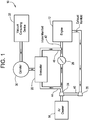
- the engine air system 10 may include an internal combustion engine 12, an air cleaner 14, an evacuator 20, a compressor 24, a turbine 26, a throttle 28, a vacuum reservoir or canister 30, and a vacuum consuming device 32.
- the internal combustion engine 12 may be, for example, a spark ignited (SI) engine or a compression ignition (CI) engine.
- the internal combustion engine 12 may be included in an electric motor/battery system that is part of a hybrid vehicle.
- the throttle 28 may be located downstream of the air cleaner 14 and the compressor 24, and upstream of an intake manifold 42 of the internal combustion engine 12.
- the internal combustion engine 12 is boosted.
- the compressor 24 and turbine 26 may be part of a turbocharger for improving the power output and overall efficiency of the internal combustion engine 12.
- the turbine 26 may include a turbine wheel (not illustrated in FIG. 1 ) that harnesses and converts exhaust energy into mechanical work through a common shaft 40 to turn a compressor wheel (not illustrated in FIG. 1 ) of the compressor 24.
- the compressor wheel ingests, compresses, and feeds air at elevated operating pressures into the intake manifold 42 of the internal combustion engine 12.
- FIGS. 1 and 2 illustrate a boosted engine, it is to be understood that the disclosed evacuator 20 may be used in a normally-aspirated or non-boosted engine system as well.
- the vacuum canister 30 may be supplied vacuum from the evacuator 20.
- the evacuator 20 is supplied clean air from the compressor 24. Specifically, clean air at atmospheric pressure exits the air cleaner 14 and may be compressed by the compressor 24 before passing through the evacuator 20.
- the evacuator 20 may be used to supply vacuum to the vacuum canister 30. It is to be understood that although FIG. 1 illustrates the evacuator 20 being supplied air from the compressor 24, in another embodiment, the evacuator 20 may be positioned to receive air from the air cleaner 14 as well, for example in the case of a normally-aspirated or non-boosted engine system.
- the throttle 28 may be opened as an operator depresses upon an accelerator pedal (not shown). When the throttle 28 is opened, compressed air from the compressor 24 is free to fill the intake manifold 42 of the internal combustion engine 12, thereby increasing the pressure at the intake manifold 42. Those skilled in the art will appreciate that the throttle 28 may be positioned in a plurality of partially opened positions based on the amount of depression of the accelerator (not shown). Since the engine air system 10 is turbocharged, the pressure at the intake manifold 42 may increase to a pressure that is above atmosphere as the throttle 28 is opened.
- the evacuator 20 may include a first engine air connection 44, a second engine air connection 46, and a pneumatically-actuated vacuum pump 50 (shown in FIG. 2 ).
- the first engine air connection 44 of the evacuator 20 may be fluidly connected to the engine air system 10 at a location downstream of the compressor 24 and upstream of the throttle 28.
- the second engine air connection 46 of the evacuator 20 may be fluidly connected to the engine air system 10 at a location upstream of the intake manifold 42 and downstream of the throttle 28.
- the evacuator 20 is illustrated as supplying vacuum to the vacuum canister 30, those skilled in the art will appreciate that in an alternative embodiment, the evacuator 20 may directly supply vacuum to the vacuum consuming device 32.
- the vacuum consuming device 32 may be a device requiring vacuum, such as a brake booster.
- the vacuum consuming device 32 may also include additional vacuum consumers as well, such as, for example, turbocharger waste gate actuators, heating and ventilation actuators, driveline actuators (e.g., four wheel drive actuators), fuel vapor purging systems, engine crankcase ventilation, and fuel system leak testing systems.
- FIG. 2 is a schematic diagram of an embodiment of the evacuator 20 shown in FIG. 1 , and illustrates the pneumatically-actuated vacuum pump 50.
- the pneumatically-actuated vacuum pump 50 may be a converging, diverging nozzle assembly with three or more connections.
- the pneumatically-actuated vacuum pump 50 includes a motive port 70 fluidly connected to the first engine air connection 44, a discharge port 74 fluidly connected to the second engine air connection 46, and one or more suction ports 72 fluidly connected to the vacuum canister 30 ( FIG. 1 ) or to one or more devices requiring vacuum 32.
- the motive port 70 of the evacuator 50 may be fluidly connected to the engine air system 10 downstream of the compressor 24, and the discharge port 74 may be fluidly connected to the engine air system 10 upstream of the intake manifold 42.
- FIG. 2 illustrates one suction ports 72 it is to be understood that the pneumatically-actuated vacuum pump 50 may include additional suction port(s) 72.
- the pneumatically-actuated vacuum pump 50 may act as an ejector, where boosted air that is above atmospheric pressure may be fed to the evacuator 20 through the motive port 70.
- the motive port 70 of the pneumatically-actuated vacuum pump 50 may be fluidly connected to a source of air that is at atmospheric pressure such that the pneumatically-actuated vacuum pump 50 acts as an aspirator.
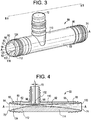
- FIG. 3 is a perspective view
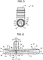
- FIG. 4 is a side cross-sectional view taken along line B-B of FIG. 3
- FIG. 5 is an end view from the perspective of the motive port 70.
- a passageway 80 that extends along axis A-A of the pneumatically-actuated vacuum pump 50 includes a first tapering portion 92 (also referred to as a motive cone) in a motive section 90 of the passageway 80.
- the passageway 80 also includes a second tapering portion 93 (also referred to as a discharge cone) in a discharge section 95 of the passageway 80.
- the first tapering portion 92 of the passageway 80 includes an inlet end 94 and an outlet end 96.
- the second tapering portion 93 of the passageway 80 also includes an inlet end 98 and an outlet end 100.
- the first tapering portion 92 of the pneumatically-actuated vacuum pump 50 is fluidly coupled to the second tapering portion 93 by a Venturi gap 102.
- the Venturi gap 102 is a fluid junction that places the suction port 72 in fluid communication with the motive section 90 and the discharge section 92 of the pneumatically-actuated vacuum pump 50.
- the Venturi gap 102 is the lineal distance L measured between the outlet end 96 of the first tapering portion 92 and the inlet end 98 of the second tapering portion 93.
- the inlet ends 94, 98 and the outlet ends 96, 100 include any type of profile, such as, but not limited to, a circular shape, an ellipse shape, or another curved or polygonal form.
- the gradually, continuously tapering inner diameter extending from inlet ends 94, 98 and the outlet ends 96, 100 of the passageway 80 may define a hyperboloid, a paraboloid, or a cone.
- Some exemplary configurations for the outlet end 96 of the first tapering portion 92 and the inlet end 98 of the second tapering portion 93 are presented in FIGS. 4-6 of co-pending U.S. Patent Application No. 14/294,727 , filed on June 3, 2014.
- a plurality of additional Venturi gaps may be located downstream of the Venturi gap 102, along the second tapering portion 93 of the pneumatically-actuated vacuum pump 50.
- Some exemplary configurations of a pneumatically-actuated vacuum pump with a plurality of Venturi gaps are presented in FIGS. 2-5C of co-pending U.S. Patent Application No. 14/452,651 filed on August 6, 2014 .
- the pneumatically-actuated vacuum pump 5 includes a fin 82 that is substantially aligned with a central axis of symmetry A-A of the pneumatically-actuated vacuum pump 50.
- the fin 82 is used to reduce the motive flow rate required by the evacuator 20 in order to produce a specific amount of vacuum that is supplied to the vacuum canister 30.
- the fin 82 also increases the perimeter area between the motive flow and the suction flow, increasing suction flow.
- the fin 82 is a rigid structure integrally formed into a housing 110 of the pneumatically actuated vacuum pump 50, for example as part of an injection molding process.
- the fin 82 may alternately be permanently attached to the housing 100 of the pneumatically-actuated vacuum pump 50.
- the integral or permanent attachment of the fin 82 to the housing 110 of the pump 50 provides stability to the fin 82 in use, substantially preventing or minimizing vibration of the fin 82, which could otherwise increase turbulence and/or noise.
- the fin functions similarly to a fletch insert, as disclosed and described in copending U.S. Provisional Pat. App. No. 62/042,569, filed August 27, 2014 .
- the fin 82 may include a first portion 112 disposed within the first tapering portion 92 of the pneumatically-actuated vacuum pump 50 and a second portion 114 disposed within the second tapering portion 93 of the pump 50.
- the fin 82 extends radially inwardly towards the axis of symmetry A-A from an inner surface 122 of the tapering portions 92, 93, into a void 124 defined by the passageway 80.
- the fin 82 extends radially into the void 124 from a base 118 of the fin 82 to terminate in an upper surface 120 thereof.
- the base 118 extends through the passageway 80 coextensively with the inner surface 122 in the direction of the axis of symmetry A-A.
- the fin 82 may have a non-uniform height along its length, and in one embodiment, generally increase in height through the first tapering portion 92 and generally decrease in height through the second tapering portion 93.
- the fin 82 has a rounded, trapezoidal cross-sectional shape (seen in FIGS. 3 and 5 ).
- the fin 82 is not limited as such, but may have, for example, a cross-sectional shape that is substantially semi-elliptical, semi-circular, or any of a variety of curved or polygonal shapes, depending on the motive flow characteristics required for the particular application of the pneumatically-actuated vacuum pump 50.
- the fin 82 extends continuously from the inlet end 94 of the first tapering portion 92, through the Venturi gap 102, and on to the outlet end 100 of the second tapering portion 93.
- the fin 82 may gradually increase in height through the first tapering portion 92 to a maximum height at or near the Venturi gap 102, and then gradually decrease in height through the second tapering portion 93.
- the fin 82 extends along substantially the entire distance between the outlet ends 96, 100 (as shown in FIG. 4 ), or alternately begin/terminate at intermediate location(s) within the length of the passageway 80.
- the fin 82 provides various advantages and benefits during operation of the pneumatically-actuated vacuum pump 50.
- the fin 82 decreases the amount of motive flow or air flow required by the pneumatically-actuated vacuum pump 50 in order to generate a specific amount of suction. This means that the pneumatically-actuated vacuum pump 50 requires less air flow than an evacuator that does not include a fin 82 in order to create the same amount of vacuum.
- the fin 82 fills up or blocks off a portion of the void 124 located within the passageway 80 of the pneumatically-actuated vacuum pump 50.
- the motive flow entering the pneumatically-actuated vacuum pump 50 has a smaller volume to fill in the passageway 80 of the pump 50, as compared to an evacuator of the same dimensions, but lacking the fin 82.
- less air is required to enter the motive port 70 (see FIG. 3 ) of the pneumatically-actuated vacuum pump 50 in order to generate the same amount of suction in the vacuum canister 30, as compared to an evacuator that does not include a fin.
- FIGS. 6-8 depict an alternative embodiment of a pneumatically-actuated vacuum pump 50', in which a fin 82' does not extend through the Venturi gap 102.
- a gap 116 located between a first portion 112' and a second portion 114' of the fin 82', where each portion 112', 114' is a separate fin segment.
- FIGS. 7 and 8 which are cross-sectional views of the passageway 80 taken at the Venturi gap 102 along lines C-C and D-D of FIG.
- each of the portions 112', 114' of the fin 82' terminates in an end 126, 128 at or near the Venturi gap 102.
- Each end 126, 128 has a face 127, 129 oriented toward the Venturi gap 102.
- the faces 127, 129 (or a plane defined by either face 127, 129) may orthogonally or obliquely intersect the axis of symmetry A-A.
- the face 127 of the first portion 112' and the face 129 of the second portion 114' may be generally aligned across the Venturi gap 102.
- the ends 126, 128 may be substantially identically positioned within their respective tapering portions 92, 93 relative to the axis of symmetry A-A, such that the face 127 of the first portion 112' would substantially coincide with the face 129 of the second portion 114' if one of the ends 126, 128 were extended linearly across the Venturi gap 102.
- the ends 126, 128 may nonetheless be generally aligned if each end 126, 128 is positioned within its respective tapering portions 92, 93 to maximize symmetrical positioning of the faces 127, 129 relative to each other across the Venturi gap 102.
- FIGS. 7 and 8 show faces 127, 129 with the generally the same shape but of different sizes, where both are generally aligned through centered placement of the portions 112', 114' within the tapering portions 92, 93.
- the faces 126, 128 of the portions 112', 114' of the fin 82' influence the interior perimeter shapes/profiles of the outlet end 96 of the first tapering portion 92 and the inlet end 98 of the second tapering portion 93.
- the interior perimeter shapes of both ends 96, 98, including the fin 82' are generally horseshoe-shaped (i.e., the cross-sectional shape of the void 24 of the passageway 80 at or near each of the ends 96, 98 is generally horseshoe-shaped).
- this illustration is merely exemplary, and the interior perimeter shape of the ends 96, 98 may include other profiles as well.
- the height H 1 and/or width W 1 of the portion 112' of fin 82' at the Venturi gap 102 is greater than the height H 2 and/or width W 2 of the portion 114' of fin 82' at the Venturi gap 102.
- the width of the fin 82' tapers as the fin 82' approaches the Venturi gap 102 (on one or both ends 126, 128), such that the faces 127, 129 are substantially thinner than depicted in FIGS. 7 and 8 (for example, almost linear, in one embodiment).
- the fin 82' may include only the first portion 112' through the first tapering portion 92, and omits the second portion 114' in the second tapering portion 93.
- the fin 82' provides further opportunities to fine tune the desired suction flow rate and depth of vacuum of the pump 50', based on the relationship between the shapes, size, and positioning of the faces 127, 129 of the fin 82' on either side of the Venturi gap 102.
- the perimeter shape of the outlet end 96 also impacts the suction flow rate. Specifically, a larger perimeter results in increased suction flow.
- the magnitude of the offset impacts both the suction flow rate and the depth of vacuum generated.
- Fin 82' provides enhanced options for both maximizing suction flow rate and increasing the depth of vacuum.
- the shape of the face 127 at the end 126 of first portion 112' of the fin 82' substantially increases the total internal perimeter of the outlet end 96 (as shown, defining a generally horseshoe shaped void), as compared to an outlet end for a similarly-sized first tapered portion 92 without a fin 82', which would be generally elliptical in shape. Accordingly, the potential suction flow rate of the pump 50' across a Venturi gap 102 is substantially increased as compared to an identical pump lacking a fin 82'.
- the fin 82' also expands the design options for controlling depth of vacuum parameters for the pump 50'. Depth of vacuum is a function of the magnitude of the offset between the inlet end 98 and the outlet end 96 of the Venturi gap 102. The smaller the offset, the greater the depth of vacuum. Accordingly, in addition to (or instead of) varying the shape and/or size of the overall perimeter shapes of the ends 96, 98 aside from the fin 82' (in other words, the overarching elliptical shape, in the example of FIGS.
- offset of the pump 50' can be adjusted by varying the size and/or changing the shape of the face 128 of the second portion 114' of the fin 82' at the inlet end 98.
- offset can be increased by reducing the height H 2 and/or width W 2 of the face 128 on the inlet end 98 relative to the height H 1 and/or width W 1 of the face 126 of the outlet end 126.
- the shape and size of the first and second portions 112', 114' of the fin 82' can be optimized relative to each other, to set the suction flow rate and the depth of vacuum characteristics of the pump 50' according to the required performance criteria.
Landscapes
- Engineering & Computer Science (AREA)
- Mechanical Engineering (AREA)
- General Engineering & Computer Science (AREA)
- Chemical & Material Sciences (AREA)
- Combustion & Propulsion (AREA)
- Physics & Mathematics (AREA)
- Fluid Mechanics (AREA)
- Jet Pumps And Other Pumps (AREA)
- Valves And Accessory Devices For Braking Systems (AREA)
Claims (11)
- Évacuateur (50, 50'), comprenant :un corps (110) définissant un axe de symétrie (A-A) central, une première portion effilée (92), une seconde portion effilée (93) définissant un passage (80) à travers le corps, au moins un espace Venturi (102) situé entre une extrémité de sortie (96) de la première portion effilée et une extrémité d'entrée (98) de la seconde portion effilée, et un orifice d'aspiration (72) en communication de fluide avec l'espace Venturi (102), dans lequel l'extrémité de sortie (96) de la première portion effilée définit une première ouverture de forme elliptique dans l'au moins un espace Venturi ;caractérisé en ce queune seule ailette (82, 82') formant un seul bloc avec le corps (110) fait saillie radialement vers l'intérieur dans le passage (80) à partir d'une surface intérieure (122) des première et seconde portions effilées (92, 93) et s'étend dans la direction de l'axe de symétrie (A-A) central avec une longueur à partir d'un point de départ au niveau de l'extrémité d'entrée (94) de la première portion effilée (92) ou d'une position intermédiaire dans la première portion effilée (92) du corps jusqu'à un point final au niveau de l'extrémité de sortie (100) de la seconde portion effilée (93) ou d'une position intermédiaire dans la seconde portion effilée (93) ;dans lequel l'ailette (82) est soit continue à travers l'espace Venturi (102) soit discontinue au niveau de l'espace Venturi (102) et a une base qui s'étend à travers le passage (80) de manière coextensive avec la surface intérieure (122).
- Évacuateur selon la revendication 1, dans lequel l'ailette (82) est discontinue au niveau de l'espace Venturi (102) et définit une première face (127) au niveau de l'extrémité de sortie (96) de la première portion effilée et une seconde face (129) au niveau de l'extrémité d'entrée (98) de la seconde portion effilée.
- Évacuateur selon la revendication 2, dans lequel une longueur de périmètre de la seconde face (129) est plus grande qu'un périmètre de la première face (127).
- Évacuateur selon la revendication 1, dans lequel l'ailette (82) a une hauteur variable le long d'une longueur de l'ailette.
- Évacuateur selon la revendication 4, dans lequel l'ailette (82) a une hauteur maximale au niveau d'un espace Venturi (102).
- Évacuateur selon la revendication 1, dans lequel la première portion effilée (92) est une portion motrice convergente et dans lequel la seconde portion effilée (93) est une portion de rejet divergente.
- Évacuateur selon la revendication 1, dans lequel l'extrémité d'entrée (98) de la seconde portion effilée (93) définit une seconde ouverture de forme elliptique au niveau de l'espace Venturi (102).
- Évacuateur selon la revendication 1, dans lequel l'ailette (82) a une forme généralement semi-elliptique ou semi-circulaire en tant que forme transversale de celle-ci.
- Évacuateur selon la revendication 8, dans lequel la forme de l'espace vide au niveau de l'extrémité de sortie (96) de la première portion effilée (92) est un espace vide généralement en forme de fer à cheval.
- Système d'air de moteur (10) à turbocompresseur, comprenant :un dispositif (32) nécessitant un vide ;un turbocompresseur (24 et 26) ayant un compresseur relié de manière fluidique à un collecteur d'admission (42) d'un moteur (12) ; etun évacuateur (20) selon l'une quelconque des revendications 1 à 9 ;dans lequel la seconde portion effilée (93) de l'évacuateur (20) est reliée de manière fluidique au collecteur d'admission (42) du moteur (12) à un emplacement en aval du compresseur (24), et l'orifice d'aspiration (72) de l'évacuateur (20) est relié de manière fluidique au dispositif (32) nécessitant un vide.
- Système d'air de moteur non amplifié, comprenant :un dispositif (32) nécessitant un vide ;un collecteur d'admission (42) d'un moteur (12) ; etun évacuateur (20) selon l'une quelconque des revendications 1 à 9 ; etdans lequel la seconde portion effilée (93) de l'évacuateur (20) est reliée de manière fluidique au collecteur d'admission (42) du moteur (12) et l'orifice d'aspiration (72) de l'évacuateur (20) est relié de manière fluidique au dispositif (32) nécessitant un vide.
Applications Claiming Priority (2)
| Application Number | Priority Date | Filing Date | Title |
|---|---|---|---|
| US14/631,287 US10151283B2 (en) | 2015-02-25 | 2015-02-25 | Evacuator with motive fin |
| PCT/US2016/019010 WO2016137912A1 (fr) | 2015-02-25 | 2016-02-23 | Évacuateur à ailette motrice |
Publications (3)
| Publication Number | Publication Date |
|---|---|
| EP3262291A1 EP3262291A1 (fr) | 2018-01-03 |
| EP3262291A4 EP3262291A4 (fr) | 2018-08-15 |
| EP3262291B1 true EP3262291B1 (fr) | 2020-10-14 |
Family
ID=56690304
Family Applications (1)
| Application Number | Title | Priority Date | Filing Date |
|---|---|---|---|
| EP16756137.2A Active EP3262291B1 (fr) | 2015-02-25 | 2016-02-23 | Évacuateur à ailette motrice |
Country Status (7)
| Country | Link |
|---|---|
| US (1) | US10151283B2 (fr) |
| EP (1) | EP3262291B1 (fr) |
| JP (1) | JP6696993B2 (fr) |
| KR (1) | KR102249559B1 (fr) |
| CN (1) | CN107407235B (fr) |
| BR (1) | BR112017018218B1 (fr) |
| WO (1) | WO2016137912A1 (fr) |
Families Citing this family (7)
| Publication number | Priority date | Publication date | Assignee | Title |
|---|---|---|---|---|
| US9827963B2 (en) * | 2013-06-11 | 2017-11-28 | Dayco Ip Holdings, Llc | Aspirators for producing vacuum using the Venturi effect |
| US9816532B2 (en) * | 2015-06-11 | 2017-11-14 | Ford Global Technologies, Llc | Aspirator for internal combustion engine having integrated flow bypass and check valve |
| WO2017040150A1 (fr) * | 2015-08-28 | 2017-03-09 | Dayco Ip Holdings, Inc. | Restricteurs utilisant l'effet venturi |
| US10857507B2 (en) | 2016-03-23 | 2020-12-08 | Alfa Laval Corporate Ab | Apparatus for dispersing particles in a liquid |
| US11408380B2 (en) * | 2020-12-24 | 2022-08-09 | Dayco Ip Holdings, Llc | Devices for producing vacuum using the Venturi effect having a hollow fletch |
| US11614098B2 (en) * | 2020-12-24 | 2023-03-28 | Dayco Ip Holdings, Llc | Devices for producing vacuum using the Venturi effect having a solid fletch |
| KR102514648B1 (ko) * | 2021-04-22 | 2023-03-29 | 고영추 | 진공 발생장치 |
Citations (1)
| Publication number | Priority date | Publication date | Assignee | Title |
|---|---|---|---|---|
| US6293294B1 (en) * | 1999-06-24 | 2001-09-25 | Hydrosurge, Inc. | Method and apparatus for fluid mixing and dispensing |
Family Cites Families (86)
| Publication number | Priority date | Publication date | Assignee | Title |
|---|---|---|---|---|
| US166762A (en) | 1875-08-17 | Improvement in injectors | ||
| US139799A (en) | 1873-06-10 | Improvement in ejectors | ||
| US1845969A (en) | 1928-04-02 | 1932-02-16 | Trico Products Corp | Suction augmenting device |
| US1902729A (en) | 1931-08-15 | 1933-03-21 | Schmidt Paul | Multistage liquid driven ejector for delivering liquids |
| US2183561A (en) * | 1938-03-17 | 1939-12-19 | Clyde M Hamblin | Mechanical foam generator |
| US2319228A (en) * | 1940-05-10 | 1943-05-18 | Reynolds Allen | Vacuum pressure pump |
| US2391734A (en) | 1945-02-12 | 1945-12-25 | Alfred E Nittka | Pumping system and apparatus |
| US2396290A (en) | 1945-03-01 | 1946-03-12 | Schwarz Sigmund | Sludge pump |
| US2512479A (en) | 1949-02-17 | 1950-06-20 | Callejo Modesto | Backflow preventer |
| US3234932A (en) | 1960-09-19 | 1966-02-15 | Forrest M Bird | Respirator |
| US3430437A (en) | 1966-10-05 | 1969-03-04 | Holley Carburetor Co | Automotive exhaust emission system |
| US3467022A (en) | 1968-03-01 | 1969-09-16 | L & A Products Inc | Aspirator control apparatus |
| DE1750021A1 (de) | 1968-03-21 | 1971-01-07 | Fichtel & Sachs Ag | Ventileinrichtung fuer hydraulische,pneumatische oder hydropneumatische Einrichtungen |
| US3826281A (en) | 1969-10-29 | 1974-07-30 | Us Navy | Throttling ball valve |
| US3636983A (en) | 1970-08-14 | 1972-01-25 | Edwin J Keyser | Method and apparatus for increasing fluid flow |
| US3754841A (en) | 1971-05-14 | 1973-08-28 | Bendix Corp | Vacuum intensified brake booster system |
| DE2717685C3 (de) | 1977-04-21 | 1981-04-02 | Audi Nsu Auto Union Ag, 7107 Neckarsulm | Brennkraftmaschine für Kraftfahrzeuge |
| US4308138A (en) | 1978-07-10 | 1981-12-29 | Woltman Robert B | Treating means for bodies of water |
| US4499034A (en) | 1982-09-02 | 1985-02-12 | The United States Of America As Represented By The United States Department Of Energy | Vortex-augmented cooling tower-windmill combination |
| US4554786A (en) | 1982-09-16 | 1985-11-26 | Nissin Kogyo Kabushiki Kaisha | Vacuum source device for vacuum booster for vehicles |
| AU545569B2 (en) | 1982-09-16 | 1985-07-18 | Honda Giken Kogyo Kabushiki Kaisha | Vacuum source device |
| US4519423A (en) * | 1983-07-08 | 1985-05-28 | University Of Southern California | Mixing apparatus using a noncircular jet of small aspect ratio |
| US4634559A (en) | 1984-02-29 | 1987-01-06 | Aluminum Company Of America | Fluid flow control process |
| IL74282A0 (en) | 1985-02-08 | 1985-05-31 | Dan Greenberg | Multishaft jet suction device |
| US4683916A (en) | 1986-09-25 | 1987-08-04 | Burron Medical Inc. | Normally closed automatic reflux valve |
| US4759691A (en) | 1987-03-19 | 1988-07-26 | Kroupa Larry G | Compressed air driven vacuum pump assembly |
| US4880358A (en) | 1988-06-20 | 1989-11-14 | Air-Vac Engineering Company, Inc. | Ultra-high vacuum force, low air consumption pumps |
| US4951708A (en) | 1988-11-30 | 1990-08-28 | General Motors Corporation | Vacuum check valve |
| US5005550A (en) * | 1989-12-19 | 1991-04-09 | Chrysler Corporation | Canister purge for turbo engine |
| US5108266A (en) | 1991-05-29 | 1992-04-28 | Allied-Signal Inc. | Check valve with aspirating function |
| US5188141A (en) | 1991-12-03 | 1993-02-23 | Siemens Automotive Limited | Vacuum boost valve |
| DE9210496U1 (de) | 1992-08-06 | 1993-12-02 | Volkmann, Thilo, 59514 Welver | Mehrstufige Ejektorpumpe |
| US5291916A (en) | 1992-12-28 | 1994-03-08 | Excel Industries, Inc. | Check valve |
| DE4310761C2 (de) | 1993-04-01 | 1995-10-12 | Kayser A Gmbh & Co Kg | Strahlpumpe |
| JPH08174860A (ja) | 1994-10-26 | 1996-07-09 | Seiko Epson Corp | インクジェットプリンタ用インクカートリッジ |
| WO1996026156A2 (fr) | 1995-02-23 | 1996-08-29 | Ecolab Inc. | Appareil et procede pour distribuer une solution visqueuse prete a l'emploi |
| US6035881A (en) * | 1997-05-15 | 2000-03-14 | Walter Alfmeier Ag Prazisions-Baugruppenelemente | Checkvalve unit |
| SE511716E5 (sv) | 1998-03-20 | 2009-01-28 | Piab Ab | Ejektorpump |
| US6308731B1 (en) | 1999-06-25 | 2001-10-30 | Itz Corporation | Vent valve |
| JP2001295800A (ja) | 1999-12-08 | 2001-10-26 | Myotoku Ltd | エゼクタ式真空発生器 |
| US6623154B1 (en) | 2000-04-12 | 2003-09-23 | Premier Wastewater International, Inc. | Differential injector |
| US6619322B1 (en) | 2000-07-27 | 2003-09-16 | The United States Of America As Represented By The Administrator Of The National Aeronautics And Space Administration | Fast-acting valve |
| WO2003023229A1 (fr) | 2001-09-06 | 2003-03-20 | Ulvac, Inc. | Systeme de pompe a vide et procede de fonctionnement d'un systeme de pompe a vide |
| CA2364735C (fr) * | 2001-12-11 | 2009-11-03 | Jan A. Korzeniowski | Aspirateur-melangeur d'air |
| US6971405B2 (en) | 2002-10-09 | 2005-12-06 | Delphi Technologies, Inc. | Check valve for fuel pump |
| US20050061378A1 (en) | 2003-08-01 | 2005-03-24 | Foret Todd L. | Multi-stage eductor apparatus |
| US20050121084A1 (en) | 2003-12-04 | 2005-06-09 | Danfoss Flomatic Corporation | Ball check valve |
| US20050172924A1 (en) * | 2004-02-09 | 2005-08-11 | Simon David N. | Air management systems |
| DE102004007319A1 (de) | 2004-02-14 | 2005-08-25 | Robert Bosch Gmbh | Vorrichtung zum Fördern von Kraftstoff |
| US20060016477A1 (en) | 2004-07-23 | 2006-01-26 | Algis Zaparackas | Vacuum enhancing check valve |
| SE528482C2 (sv) | 2005-05-25 | 2006-11-28 | Gm Global Tech Operations Inc | Bromsservosystem i en förbränningsmotor av typ Otto |
| CA2517785C (fr) | 2005-09-01 | 2009-06-02 | Masco Canada Limited | Clapet de retenue |
| US20070071618A1 (en) | 2005-09-23 | 2007-03-29 | Rhoads A/V, L.P. | Cabinet cooling fan |
| KR100629994B1 (ko) | 2005-12-30 | 2006-10-02 | 한국뉴매틱(주) | 진공 이젝터 펌프 |
| US20070152355A1 (en) * | 2005-12-30 | 2007-07-05 | Hartley John D | Cylindrical insert fluid injector / vacuum pump |
| WO2007140519A1 (fr) | 2006-06-05 | 2007-12-13 | Cullin Innovation Pty Ltd | Régulateur de fluide |
| JP4238882B2 (ja) * | 2006-06-09 | 2009-03-18 | トヨタ自動車株式会社 | 車両用エゼクタシステム |
| JP2007327453A (ja) | 2006-06-09 | 2007-12-20 | Advics:Kk | 負圧式倍力装置用エゼクタ |
| KR100767486B1 (ko) | 2006-06-26 | 2007-10-17 | 현대자동차주식회사 | 차량용 브레이크 부압 증폭기 |
| JP2008128150A (ja) | 2006-11-23 | 2008-06-05 | Aisan Ind Co Ltd | エゼクタおよびそれを用いたブレーキブースタ用負圧供給装置 |
| US7353812B1 (en) * | 2007-03-14 | 2008-04-08 | Ford Global Technologies, Llc | Vehicle engine with integral vacuum generator |
| US7779864B2 (en) | 2007-08-27 | 2010-08-24 | Mazzei Angelo L | Infusion/mass transfer of treatment substances into substantial liquid flows |
| US7628170B2 (en) | 2007-09-05 | 2009-12-08 | Emerson Electric Co. | Flow control valve |
| CN201109426Y (zh) | 2007-12-04 | 2008-09-03 | 上海汽车制动系统有限公司 | 真空增强型单向阀 |
| US7784999B1 (en) * | 2009-07-01 | 2010-08-31 | Vortex Systems (International) Ci | Eductor apparatus with lobes for optimizing flow patterns |
| US20110186151A1 (en) * | 2010-02-04 | 2011-08-04 | Bernard Joseph Sparazynski | Check valve |
| KR101814096B1 (ko) * | 2010-02-23 | 2018-01-02 | 아사히 유키자이 가부시키가이샤 | 인라인형 유체 혼합 장치 |
| US8925520B2 (en) | 2010-03-10 | 2015-01-06 | Ford Global Technologies, Llc | Intake system including vacuum aspirator |
| DE102010033091A1 (de) | 2010-08-02 | 2012-02-02 | Schaeffler Technologies Gmbh & Co. Kg | Hydraulisches Spannausgleichselement |
| CA2844503C (fr) | 2011-08-17 | 2016-04-05 | Hendrickson Usa, L.L.C. | Systeme d'evacuation pour essieu de vehicule |
| IL215426A (en) | 2011-09-27 | 2017-10-31 | Dan Geva | Complex vacuum pump |
| US10337628B2 (en) | 2012-02-20 | 2019-07-02 | Nyloncraft Incorporated | High mass flow check valve aspirator |
| US9022007B2 (en) | 2012-03-09 | 2015-05-05 | Ford Global Technologies, Llc | Throttle valve system for an engine |
| US8783231B2 (en) | 2012-03-12 | 2014-07-22 | Ford Global Technologies, Llc | Venturi for vapor purge |
| US9366432B2 (en) * | 2012-05-17 | 2016-06-14 | Capstone Turbine Corporation | Multistaged lean prevaporizing premixing fuel injector |
| US9027536B2 (en) * | 2012-06-26 | 2015-05-12 | Ford Global Technologies, Llc | Crankcase ventilation and vacuum generation |
| US9097149B2 (en) * | 2012-07-13 | 2015-08-04 | Ford Global Technologies, Llc | Aspirator for crankcase ventilation and vacuum generation |
| US9441557B2 (en) | 2012-12-13 | 2016-09-13 | Ford Global Technologies, Llc | Method and system for vacuum generation |
| GB2509182A (en) | 2012-12-21 | 2014-06-25 | Xerex Ab | Vacuum ejector with multi-nozzle drive stage and booster |
| GB2509184A (en) | 2012-12-21 | 2014-06-25 | Xerex Ab | Multi-stage vacuum ejector with moulded nozzle having integral valve elements |
| CA2888540A1 (fr) | 2013-01-14 | 2014-08-14 | Dayco Ip Holdings, Llc | Actionneur a piston commandant un clapet et son procede de fonctionnement |
| US20140301157A1 (en) * | 2013-04-03 | 2014-10-09 | Westfall Manufacturing Company | Static Mixer |
| US9827963B2 (en) * | 2013-06-11 | 2017-11-28 | Dayco Ip Holdings, Llc | Aspirators for producing vacuum using the Venturi effect |
| CN103407441A (zh) | 2013-08-16 | 2013-11-27 | 河北亚大汽车塑料制品有限公司 | 文氏阀以及真空助力装置 |
| US9382882B2 (en) | 2013-10-29 | 2016-07-05 | Ford Global Technologies, Llc | Aspirator motive flow control for vacuum generation and compressor bypass |
| US10273978B2 (en) * | 2014-08-27 | 2019-04-30 | Dayco IP, Holdings LLC | Low-cost evacuator for an engine having tuned Venturi gaps |
-
2015
- 2015-02-25 US US14/631,287 patent/US10151283B2/en active Active
-
2016
- 2016-02-23 BR BR112017018218-1A patent/BR112017018218B1/pt active IP Right Grant
- 2016-02-23 CN CN201680011998.2A patent/CN107407235B/zh active Active
- 2016-02-23 WO PCT/US2016/019010 patent/WO2016137912A1/fr active Application Filing
- 2016-02-23 JP JP2017544908A patent/JP6696993B2/ja active Active
- 2016-02-23 KR KR1020177026052A patent/KR102249559B1/ko active IP Right Grant
- 2016-02-23 EP EP16756137.2A patent/EP3262291B1/fr active Active
Patent Citations (1)
| Publication number | Priority date | Publication date | Assignee | Title |
|---|---|---|---|---|
| US6293294B1 (en) * | 1999-06-24 | 2001-09-25 | Hydrosurge, Inc. | Method and apparatus for fluid mixing and dispensing |
Also Published As
| Publication number | Publication date |
|---|---|
| KR20170121214A (ko) | 2017-11-01 |
| BR112017018218B1 (pt) | 2023-02-07 |
| WO2016137912A1 (fr) | 2016-09-01 |
| US10151283B2 (en) | 2018-12-11 |
| EP3262291A1 (fr) | 2018-01-03 |
| US20160245236A1 (en) | 2016-08-25 |
| CN107407235B (zh) | 2020-09-11 |
| EP3262291A4 (fr) | 2018-08-15 |
| JP2018508698A (ja) | 2018-03-29 |
| BR112017018218A2 (pt) | 2018-04-17 |
| JP6696993B2 (ja) | 2020-05-20 |
| KR102249559B1 (ko) | 2021-05-07 |
| CN107407235A (zh) | 2017-11-28 |
Similar Documents
| Publication | Publication Date | Title |
|---|---|---|
| EP3262291B1 (fr) | Évacuateur à ailette motrice | |
| KR102240990B1 (ko) | 복수의 벤튜리 틈 및 체크 밸브를 갖는 공압 작동식 진공 펌프 | |
| KR102256162B1 (ko) | 다중-포트 흡출기를 갖는 흡출기 시스템 | |
| CN107110007B (zh) | 曲轴箱通风抽空装置 | |
| EP3822135A1 (fr) | Évacuateur à faible coût pour moteur ayant des espaces venturi accordés | |
| JP6756699B2 (ja) | デュアルベンチュリーデバイス | |
| EP3227548B1 (fr) | Système d'évacuation permettant de fournir une dépression à aspiration élevée ou un débit à aspiration élevée | |
| CN109715998B (zh) | 用于产生真空的文丘里装置及其系统 | |
| US20160061164A1 (en) | Vacuum producer including an aspirator and an ejector | |
| BR112017012297B1 (pt) | Sistema de ar de um motor turbo-alimentado |
Legal Events
| Date | Code | Title | Description |
|---|---|---|---|
| STAA | Information on the status of an ep patent application or granted ep patent |
Free format text: STATUS: THE INTERNATIONAL PUBLICATION HAS BEEN MADE |
|
| PUAI | Public reference made under article 153(3) epc to a published international application that has entered the european phase |
Free format text: ORIGINAL CODE: 0009012 |
|
| STAA | Information on the status of an ep patent application or granted ep patent |
Free format text: STATUS: REQUEST FOR EXAMINATION WAS MADE |
|
| 17P | Request for examination filed |
Effective date: 20170922 |
|
| AK | Designated contracting states |
Kind code of ref document: A1 Designated state(s): AL AT BE BG CH CY CZ DE DK EE ES FI FR GB GR HR HU IE IS IT LI LT LU LV MC MK MT NL NO PL PT RO RS SE SI SK SM TR |
|
| AX | Request for extension of the european patent |
Extension state: BA ME |
|
| DAV | Request for validation of the european patent (deleted) | ||
| DAX | Request for extension of the european patent (deleted) | ||
| A4 | Supplementary search report drawn up and despatched |
Effective date: 20180717 |
|
| RIC1 | Information provided on ipc code assigned before grant |
Ipc: F02M 35/10 20060101AFI20180711BHEP Ipc: F04F 5/20 20060101ALI20180711BHEP Ipc: F04F 5/46 20060101ALI20180711BHEP Ipc: F04F 5/44 20060101ALI20180711BHEP |
|
| STAA | Information on the status of an ep patent application or granted ep patent |
Free format text: STATUS: EXAMINATION IS IN PROGRESS |
|
| 17Q | First examination report despatched |
Effective date: 20190416 |
|
| GRAP | Despatch of communication of intention to grant a patent |
Free format text: ORIGINAL CODE: EPIDOSNIGR1 |
|
| STAA | Information on the status of an ep patent application or granted ep patent |
Free format text: STATUS: GRANT OF PATENT IS INTENDED |
|
| INTG | Intention to grant announced |
Effective date: 20200512 |
|
| GRAS | Grant fee paid |
Free format text: ORIGINAL CODE: EPIDOSNIGR3 |
|
| GRAA | (expected) grant |
Free format text: ORIGINAL CODE: 0009210 |
|
| STAA | Information on the status of an ep patent application or granted ep patent |
Free format text: STATUS: THE PATENT HAS BEEN GRANTED |
|
| AK | Designated contracting states |
Kind code of ref document: B1 Designated state(s): AL AT BE BG CH CY CZ DE DK EE ES FI FR GB GR HR HU IE IS IT LI LT LU LV MC MK MT NL NO PL PT RO RS SE SI SK SM TR |
|
| REG | Reference to a national code |
Ref country code: GB Ref legal event code: FG4D |
|
| REG | Reference to a national code |
Ref country code: AT Ref legal event code: REF Ref document number: 1323848 Country of ref document: AT Kind code of ref document: T Effective date: 20201015 Ref country code: CH Ref legal event code: EP |
|
| REG | Reference to a national code |
Ref country code: DE Ref legal event code: R096 Ref document number: 602016045855 Country of ref document: DE |
|
| REG | Reference to a national code |
Ref country code: IE Ref legal event code: FG4D |
|
| REG | Reference to a national code |
Ref country code: AT Ref legal event code: MK05 Ref document number: 1323848 Country of ref document: AT Kind code of ref document: T Effective date: 20201014 |
|
| REG | Reference to a national code |
Ref country code: NL Ref legal event code: MP Effective date: 20201014 |
|
| PG25 | Lapsed in a contracting state [announced via postgrant information from national office to epo] |
Ref country code: FI Free format text: LAPSE BECAUSE OF FAILURE TO SUBMIT A TRANSLATION OF THE DESCRIPTION OR TO PAY THE FEE WITHIN THE PRESCRIBED TIME-LIMIT Effective date: 20201014 Ref country code: GR Free format text: LAPSE BECAUSE OF FAILURE TO SUBMIT A TRANSLATION OF THE DESCRIPTION OR TO PAY THE FEE WITHIN THE PRESCRIBED TIME-LIMIT Effective date: 20210115 Ref country code: RS Free format text: LAPSE BECAUSE OF FAILURE TO SUBMIT A TRANSLATION OF THE DESCRIPTION OR TO PAY THE FEE WITHIN THE PRESCRIBED TIME-LIMIT Effective date: 20201014 Ref country code: PT Free format text: LAPSE BECAUSE OF FAILURE TO SUBMIT A TRANSLATION OF THE DESCRIPTION OR TO PAY THE FEE WITHIN THE PRESCRIBED TIME-LIMIT Effective date: 20210215 Ref country code: NO Free format text: LAPSE BECAUSE OF FAILURE TO SUBMIT A TRANSLATION OF THE DESCRIPTION OR TO PAY THE FEE WITHIN THE PRESCRIBED TIME-LIMIT Effective date: 20210114 Ref country code: NL Free format text: LAPSE BECAUSE OF FAILURE TO SUBMIT A TRANSLATION OF THE DESCRIPTION OR TO PAY THE FEE WITHIN THE PRESCRIBED TIME-LIMIT Effective date: 20201014 |
|
| REG | Reference to a national code |
Ref country code: LT Ref legal event code: MG4D |
|
| PG25 | Lapsed in a contracting state [announced via postgrant information from national office to epo] |
Ref country code: BG Free format text: LAPSE BECAUSE OF FAILURE TO SUBMIT A TRANSLATION OF THE DESCRIPTION OR TO PAY THE FEE WITHIN THE PRESCRIBED TIME-LIMIT Effective date: 20210114 Ref country code: IS Free format text: LAPSE BECAUSE OF FAILURE TO SUBMIT A TRANSLATION OF THE DESCRIPTION OR TO PAY THE FEE WITHIN THE PRESCRIBED TIME-LIMIT Effective date: 20210214 Ref country code: LV Free format text: LAPSE BECAUSE OF FAILURE TO SUBMIT A TRANSLATION OF THE DESCRIPTION OR TO PAY THE FEE WITHIN THE PRESCRIBED TIME-LIMIT Effective date: 20201014 Ref country code: PL Free format text: LAPSE BECAUSE OF FAILURE TO SUBMIT A TRANSLATION OF THE DESCRIPTION OR TO PAY THE FEE WITHIN THE PRESCRIBED TIME-LIMIT Effective date: 20201014 Ref country code: ES Free format text: LAPSE BECAUSE OF FAILURE TO SUBMIT A TRANSLATION OF THE DESCRIPTION OR TO PAY THE FEE WITHIN THE PRESCRIBED TIME-LIMIT Effective date: 20201014 Ref country code: AT Free format text: LAPSE BECAUSE OF FAILURE TO SUBMIT A TRANSLATION OF THE DESCRIPTION OR TO PAY THE FEE WITHIN THE PRESCRIBED TIME-LIMIT Effective date: 20201014 Ref country code: SE Free format text: LAPSE BECAUSE OF FAILURE TO SUBMIT A TRANSLATION OF THE DESCRIPTION OR TO PAY THE FEE WITHIN THE PRESCRIBED TIME-LIMIT Effective date: 20201014 |
|
| PG25 | Lapsed in a contracting state [announced via postgrant information from national office to epo] |
Ref country code: HR Free format text: LAPSE BECAUSE OF FAILURE TO SUBMIT A TRANSLATION OF THE DESCRIPTION OR TO PAY THE FEE WITHIN THE PRESCRIBED TIME-LIMIT Effective date: 20201014 |
|
| REG | Reference to a national code |
Ref country code: DE Ref legal event code: R097 Ref document number: 602016045855 Country of ref document: DE |
|
| PG25 | Lapsed in a contracting state [announced via postgrant information from national office to epo] |
Ref country code: RO Free format text: LAPSE BECAUSE OF FAILURE TO SUBMIT A TRANSLATION OF THE DESCRIPTION OR TO PAY THE FEE WITHIN THE PRESCRIBED TIME-LIMIT Effective date: 20201014 Ref country code: SK Free format text: LAPSE BECAUSE OF FAILURE TO SUBMIT A TRANSLATION OF THE DESCRIPTION OR TO PAY THE FEE WITHIN THE PRESCRIBED TIME-LIMIT Effective date: 20201014 Ref country code: CZ Free format text: LAPSE BECAUSE OF FAILURE TO SUBMIT A TRANSLATION OF THE DESCRIPTION OR TO PAY THE FEE WITHIN THE PRESCRIBED TIME-LIMIT Effective date: 20201014 Ref country code: EE Free format text: LAPSE BECAUSE OF FAILURE TO SUBMIT A TRANSLATION OF THE DESCRIPTION OR TO PAY THE FEE WITHIN THE PRESCRIBED TIME-LIMIT Effective date: 20201014 Ref country code: SM Free format text: LAPSE BECAUSE OF FAILURE TO SUBMIT A TRANSLATION OF THE DESCRIPTION OR TO PAY THE FEE WITHIN THE PRESCRIBED TIME-LIMIT Effective date: 20201014 Ref country code: LT Free format text: LAPSE BECAUSE OF FAILURE TO SUBMIT A TRANSLATION OF THE DESCRIPTION OR TO PAY THE FEE WITHIN THE PRESCRIBED TIME-LIMIT Effective date: 20201014 |
|
| PLBE | No opposition filed within time limit |
Free format text: ORIGINAL CODE: 0009261 |
|
| STAA | Information on the status of an ep patent application or granted ep patent |
Free format text: STATUS: NO OPPOSITION FILED WITHIN TIME LIMIT |
|
| PG25 | Lapsed in a contracting state [announced via postgrant information from national office to epo] |
Ref country code: DK Free format text: LAPSE BECAUSE OF FAILURE TO SUBMIT A TRANSLATION OF THE DESCRIPTION OR TO PAY THE FEE WITHIN THE PRESCRIBED TIME-LIMIT Effective date: 20201014 |
|
| 26N | No opposition filed |
Effective date: 20210715 |
|
| PG25 | Lapsed in a contracting state [announced via postgrant information from national office to epo] |
Ref country code: MC Free format text: LAPSE BECAUSE OF FAILURE TO SUBMIT A TRANSLATION OF THE DESCRIPTION OR TO PAY THE FEE WITHIN THE PRESCRIBED TIME-LIMIT Effective date: 20201014 |
|
| GBPC | Gb: european patent ceased through non-payment of renewal fee |
Effective date: 20210223 |
|
| REG | Reference to a national code |
Ref country code: BE Ref legal event code: MM Effective date: 20210228 |
|
| PG25 | Lapsed in a contracting state [announced via postgrant information from national office to epo] |
Ref country code: LI Free format text: LAPSE BECAUSE OF NON-PAYMENT OF DUE FEES Effective date: 20210228 Ref country code: LU Free format text: LAPSE BECAUSE OF NON-PAYMENT OF DUE FEES Effective date: 20210223 Ref country code: IT Free format text: LAPSE BECAUSE OF FAILURE TO SUBMIT A TRANSLATION OF THE DESCRIPTION OR TO PAY THE FEE WITHIN THE PRESCRIBED TIME-LIMIT Effective date: 20201014 Ref country code: AL Free format text: LAPSE BECAUSE OF FAILURE TO SUBMIT A TRANSLATION OF THE DESCRIPTION OR TO PAY THE FEE WITHIN THE PRESCRIBED TIME-LIMIT Effective date: 20201014 Ref country code: CH Free format text: LAPSE BECAUSE OF NON-PAYMENT OF DUE FEES Effective date: 20210228 |
|
| PG25 | Lapsed in a contracting state [announced via postgrant information from national office to epo] |
Ref country code: SI Free format text: LAPSE BECAUSE OF FAILURE TO SUBMIT A TRANSLATION OF THE DESCRIPTION OR TO PAY THE FEE WITHIN THE PRESCRIBED TIME-LIMIT Effective date: 20201014 |
|
| PG25 | Lapsed in a contracting state [announced via postgrant information from national office to epo] |
Ref country code: IE Free format text: LAPSE BECAUSE OF NON-PAYMENT OF DUE FEES Effective date: 20210223 Ref country code: GB Free format text: LAPSE BECAUSE OF NON-PAYMENT OF DUE FEES Effective date: 20210223 Ref country code: FR Free format text: LAPSE BECAUSE OF NON-PAYMENT OF DUE FEES Effective date: 20210228 |
|
| PG25 | Lapsed in a contracting state [announced via postgrant information from national office to epo] |
Ref country code: IS Free format text: LAPSE BECAUSE OF FAILURE TO SUBMIT A TRANSLATION OF THE DESCRIPTION OR TO PAY THE FEE WITHIN THE PRESCRIBED TIME-LIMIT Effective date: 20210214 |
|
| PG25 | Lapsed in a contracting state [announced via postgrant information from national office to epo] |
Ref country code: BE Free format text: LAPSE BECAUSE OF NON-PAYMENT OF DUE FEES Effective date: 20210228 |
|
| P01 | Opt-out of the competence of the unified patent court (upc) registered |
Effective date: 20230522 |
|
| PG25 | Lapsed in a contracting state [announced via postgrant information from national office to epo] |
Ref country code: CY Free format text: LAPSE BECAUSE OF FAILURE TO SUBMIT A TRANSLATION OF THE DESCRIPTION OR TO PAY THE FEE WITHIN THE PRESCRIBED TIME-LIMIT Effective date: 20201014 |
|
| PG25 | Lapsed in a contracting state [announced via postgrant information from national office to epo] |
Ref country code: HU Free format text: LAPSE BECAUSE OF FAILURE TO SUBMIT A TRANSLATION OF THE DESCRIPTION OR TO PAY THE FEE WITHIN THE PRESCRIBED TIME-LIMIT; INVALID AB INITIO Effective date: 20160223 |
|
| PG25 | Lapsed in a contracting state [announced via postgrant information from national office to epo] |
Ref country code: MK Free format text: LAPSE BECAUSE OF FAILURE TO SUBMIT A TRANSLATION OF THE DESCRIPTION OR TO PAY THE FEE WITHIN THE PRESCRIBED TIME-LIMIT Effective date: 20201014 |
|
| PGFP | Annual fee paid to national office [announced via postgrant information from national office to epo] |
Ref country code: DE Payment date: 20240124 Year of fee payment: 9 |
|
| PG25 | Lapsed in a contracting state [announced via postgrant information from national office to epo] |
Ref country code: TR Free format text: LAPSE BECAUSE OF FAILURE TO SUBMIT A TRANSLATION OF THE DESCRIPTION OR TO PAY THE FEE WITHIN THE PRESCRIBED TIME-LIMIT Effective date: 20201014 |
|
| PG25 | Lapsed in a contracting state [announced via postgrant information from national office to epo] |
Ref country code: MT Free format text: LAPSE BECAUSE OF FAILURE TO SUBMIT A TRANSLATION OF THE DESCRIPTION OR TO PAY THE FEE WITHIN THE PRESCRIBED TIME-LIMIT Effective date: 20201014 |