EP3262286B1 - Verfahren zum betrieb eines kombikraftwerks und verbesserung des teillastwirkungsgrads - Google Patents
Verfahren zum betrieb eines kombikraftwerks und verbesserung des teillastwirkungsgrads Download PDFInfo
- Publication number
- EP3262286B1 EP3262286B1 EP16705003.8A EP16705003A EP3262286B1 EP 3262286 B1 EP3262286 B1 EP 3262286B1 EP 16705003 A EP16705003 A EP 16705003A EP 3262286 B1 EP3262286 B1 EP 3262286B1
- Authority
- EP
- European Patent Office
- Prior art keywords
- steam
- supercritical
- load operation
- steam turbine
- turbine
- Prior art date
- Legal status (The legal status is an assumption and is not a legal conclusion. Google has not performed a legal analysis and makes no representation as to the accuracy of the status listed.)
- Active
Links
Images




Classifications
-
- F—MECHANICAL ENGINEERING; LIGHTING; HEATING; WEAPONS; BLASTING
- F01—MACHINES OR ENGINES IN GENERAL; ENGINE PLANTS IN GENERAL; STEAM ENGINES
- F01K—STEAM ENGINE PLANTS; STEAM ACCUMULATORS; ENGINE PLANTS NOT OTHERWISE PROVIDED FOR; ENGINES USING SPECIAL WORKING FLUIDS OR CYCLES
- F01K23/00—Plants characterised by more than one engine delivering power external to the plant, the engines being driven by different fluids
- F01K23/02—Plants characterised by more than one engine delivering power external to the plant, the engines being driven by different fluids the engine cycles being thermally coupled
- F01K23/06—Plants characterised by more than one engine delivering power external to the plant, the engines being driven by different fluids the engine cycles being thermally coupled combustion heat from one cycle heating the fluid in another cycle
- F01K23/10—Plants characterised by more than one engine delivering power external to the plant, the engines being driven by different fluids the engine cycles being thermally coupled combustion heat from one cycle heating the fluid in another cycle with exhaust fluid of one cycle heating the fluid in another cycle
- F01K23/106—Plants characterised by more than one engine delivering power external to the plant, the engines being driven by different fluids the engine cycles being thermally coupled combustion heat from one cycle heating the fluid in another cycle with exhaust fluid of one cycle heating the fluid in another cycle with water evaporated or preheated at different pressures in exhaust boiler
-
- F—MECHANICAL ENGINEERING; LIGHTING; HEATING; WEAPONS; BLASTING
- F01—MACHINES OR ENGINES IN GENERAL; ENGINE PLANTS IN GENERAL; STEAM ENGINES
- F01K—STEAM ENGINE PLANTS; STEAM ACCUMULATORS; ENGINE PLANTS NOT OTHERWISE PROVIDED FOR; ENGINES USING SPECIAL WORKING FLUIDS OR CYCLES
- F01K23/00—Plants characterised by more than one engine delivering power external to the plant, the engines being driven by different fluids
- F01K23/02—Plants characterised by more than one engine delivering power external to the plant, the engines being driven by different fluids the engine cycles being thermally coupled
- F01K23/06—Plants characterised by more than one engine delivering power external to the plant, the engines being driven by different fluids the engine cycles being thermally coupled combustion heat from one cycle heating the fluid in another cycle
- F01K23/10—Plants characterised by more than one engine delivering power external to the plant, the engines being driven by different fluids the engine cycles being thermally coupled combustion heat from one cycle heating the fluid in another cycle with exhaust fluid of one cycle heating the fluid in another cycle
-
- F—MECHANICAL ENGINEERING; LIGHTING; HEATING; WEAPONS; BLASTING
- F01—MACHINES OR ENGINES IN GENERAL; ENGINE PLANTS IN GENERAL; STEAM ENGINES
- F01K—STEAM ENGINE PLANTS; STEAM ACCUMULATORS; ENGINE PLANTS NOT OTHERWISE PROVIDED FOR; ENGINES USING SPECIAL WORKING FLUIDS OR CYCLES
- F01K23/00—Plants characterised by more than one engine delivering power external to the plant, the engines being driven by different fluids
- F01K23/02—Plants characterised by more than one engine delivering power external to the plant, the engines being driven by different fluids the engine cycles being thermally coupled
- F01K23/06—Plants characterised by more than one engine delivering power external to the plant, the engines being driven by different fluids the engine cycles being thermally coupled combustion heat from one cycle heating the fluid in another cycle
- F01K23/10—Plants characterised by more than one engine delivering power external to the plant, the engines being driven by different fluids the engine cycles being thermally coupled combustion heat from one cycle heating the fluid in another cycle with exhaust fluid of one cycle heating the fluid in another cycle
- F01K23/101—Regulating means specially adapted therefor
-
- F—MECHANICAL ENGINEERING; LIGHTING; HEATING; WEAPONS; BLASTING
- F01—MACHINES OR ENGINES IN GENERAL; ENGINE PLANTS IN GENERAL; STEAM ENGINES
- F01K—STEAM ENGINE PLANTS; STEAM ACCUMULATORS; ENGINE PLANTS NOT OTHERWISE PROVIDED FOR; ENGINES USING SPECIAL WORKING FLUIDS OR CYCLES
- F01K3/00—Plants characterised by the use of steam or heat accumulators, or intermediate steam heaters, therein
- F01K3/18—Plants characterised by the use of steam or heat accumulators, or intermediate steam heaters, therein having heaters
- F01K3/26—Plants characterised by the use of steam or heat accumulators, or intermediate steam heaters, therein having heaters with heating by steam
-
- F—MECHANICAL ENGINEERING; LIGHTING; HEATING; WEAPONS; BLASTING
- F01—MACHINES OR ENGINES IN GENERAL; ENGINE PLANTS IN GENERAL; STEAM ENGINES
- F01K—STEAM ENGINE PLANTS; STEAM ACCUMULATORS; ENGINE PLANTS NOT OTHERWISE PROVIDED FOR; ENGINES USING SPECIAL WORKING FLUIDS OR CYCLES
- F01K7/00—Steam engine plants characterised by the use of specific types of engine; Plants or engines characterised by their use of special steam systems, cycles or processes; Control means specially adapted for such systems, cycles or processes; Use of withdrawn or exhaust steam for feed-water heating
- F01K7/16—Steam engine plants characterised by the use of specific types of engine; Plants or engines characterised by their use of special steam systems, cycles or processes; Control means specially adapted for such systems, cycles or processes; Use of withdrawn or exhaust steam for feed-water heating the engines being only of turbine type
- F01K7/18—Steam engine plants characterised by the use of specific types of engine; Plants or engines characterised by their use of special steam systems, cycles or processes; Control means specially adapted for such systems, cycles or processes; Use of withdrawn or exhaust steam for feed-water heating the engines being only of turbine type the turbine being of multiple-inlet-pressure type
-
- F—MECHANICAL ENGINEERING; LIGHTING; HEATING; WEAPONS; BLASTING
- F01—MACHINES OR ENGINES IN GENERAL; ENGINE PLANTS IN GENERAL; STEAM ENGINES
- F01K—STEAM ENGINE PLANTS; STEAM ACCUMULATORS; ENGINE PLANTS NOT OTHERWISE PROVIDED FOR; ENGINES USING SPECIAL WORKING FLUIDS OR CYCLES
- F01K7/00—Steam engine plants characterised by the use of specific types of engine; Plants or engines characterised by their use of special steam systems, cycles or processes; Control means specially adapted for such systems, cycles or processes; Use of withdrawn or exhaust steam for feed-water heating
- F01K7/16—Steam engine plants characterised by the use of specific types of engine; Plants or engines characterised by their use of special steam systems, cycles or processes; Control means specially adapted for such systems, cycles or processes; Use of withdrawn or exhaust steam for feed-water heating the engines being only of turbine type
- F01K7/22—Steam engine plants characterised by the use of specific types of engine; Plants or engines characterised by their use of special steam systems, cycles or processes; Control means specially adapted for such systems, cycles or processes; Use of withdrawn or exhaust steam for feed-water heating the engines being only of turbine type the turbines having inter-stage steam heating
-
- F—MECHANICAL ENGINEERING; LIGHTING; HEATING; WEAPONS; BLASTING
- F01—MACHINES OR ENGINES IN GENERAL; ENGINE PLANTS IN GENERAL; STEAM ENGINES
- F01K—STEAM ENGINE PLANTS; STEAM ACCUMULATORS; ENGINE PLANTS NOT OTHERWISE PROVIDED FOR; ENGINES USING SPECIAL WORKING FLUIDS OR CYCLES
- F01K7/00—Steam engine plants characterised by the use of specific types of engine; Plants or engines characterised by their use of special steam systems, cycles or processes; Control means specially adapted for such systems, cycles or processes; Use of withdrawn or exhaust steam for feed-water heating
- F01K7/32—Steam engine plants characterised by the use of specific types of engine; Plants or engines characterised by their use of special steam systems, cycles or processes; Control means specially adapted for such systems, cycles or processes; Use of withdrawn or exhaust steam for feed-water heating the engines using steam of critical or overcritical pressure
-
- Y—GENERAL TAGGING OF NEW TECHNOLOGICAL DEVELOPMENTS; GENERAL TAGGING OF CROSS-SECTIONAL TECHNOLOGIES SPANNING OVER SEVERAL SECTIONS OF THE IPC; TECHNICAL SUBJECTS COVERED BY FORMER USPC CROSS-REFERENCE ART COLLECTIONS [XRACs] AND DIGESTS
- Y02—TECHNOLOGIES OR APPLICATIONS FOR MITIGATION OR ADAPTATION AGAINST CLIMATE CHANGE
- Y02E—REDUCTION OF GREENHOUSE GAS [GHG] EMISSIONS, RELATED TO ENERGY GENERATION, TRANSMISSION OR DISTRIBUTION
- Y02E20/00—Combustion technologies with mitigation potential
- Y02E20/16—Combined cycle power plant [CCPP], or combined cycle gas turbine [CCGT]
Definitions
- aspects of the present invention relate to a combined cycle power plant, and particularly to, methods for operating a combined cycle power plant having a supercritical steam turbine, and more particularly to methods for improving the efficiency of the combined cycle power plant with supercritical steam turbine.
- a combined cycle power plant may include a gas turbine that generates power output from combustion of a fuel and air mixture.
- a heat recovery steam generator may be located downstream from the gas turbines to receive exhaust gas from the gas turbines. The heat recovery steam generator extracts energy from the exhaust gas to produce superheated steam. The superheated steam may be transferred to a steam turbine for generating additional power output.
- a steam turbine may include multiple pressure steam sections such as a high pressure steam section, an intermediate pressure steam section, and one or more low pressure steam section.
- the combined cycle power plant may be in a single-shaft application.
- a single-shaft application may include one generator that is connected to the gas turbine and the steam turbine.
- the combined cycle power plant may be in a multiple- shaft application.
- a multiple- shaft application may include multiple generators.
- Each of the multiple generators may be connected to the gas turbine and the steam turbine separately.
- Alobaid et al "Dynamic simulation of a supercritical once-through heat recovery steam generator during load changes and start/up procedures", APPLIED ENERGY, ELSEVIER SCIENCE PUBLISHERS, GB, vol. 86, no. 7-8, 1 July 2009 (2009-07-01), pages 1274-1282, XP025973523, ISSN: 0306-2619, DOI: 10. 1016/J.APENERGY.2008.09.013 a method for operation of a combined cycle power plant is known. From document US 2009/090111 A1 a steam combined cycle and method is known.
- part load operation It is often desired and required to operate the combined cycle power plant at a load below the maximum rating of the plant. This scenario is termed as part load operation. It is also known that the thermal efficiency of combined cycle Bratyon Cycle and Rankine Cycle engines is significantly reduced when operating at part loads. For example, a steam turbine in the Rankine cycle being a constant volume system would operate at reduced throttle pressure when operating at lower loads, i.e., a lower steam flow. Consequently, this operation may reduce the theoretical maximum reversible operation for steam expansion and will reduce the power output. Therefore, a need remains to improve performance of a combined cycle power plant at lower loads.
- aspects of the present invention relate to a combined cycle power plant and method for operating a combined cycle power plant, and in particular a combined cycle power plant comprising a supercritical steam turbine.
- CCPP combined cycle power plant
- a steam having parameters above the critical parameters of water is referred as a supercritical steam. That is, a steam having a pressure which is above a critical pressure of water and having a temperature which is above a critical temperature of water.
- the critical pressure of water is about 3206.2 *0,06894757 bar.
- a method for improving the efficiency impact of a part load operation of a combined cycle power plant comprises the step of initiating a base load operation of the combined cycle power plant at a supercritical steam level, or more particularly, a supercritical pressure level.
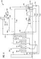
- Fig. 1 illustrates a schematic flow diagram of a combined cycle power plant 100 having a supercritical steam turbine (SST) 600 according to an example.
- the combined cycle power plant 100 comprises a gas turbine 200.
- the gas turbine 200 may generate power output from combustion of a fuel and air mixture.
- the power plant 100 comprises a heat recovery steam generator (HRSG) 500 located downstream of the gas turbine 200. Exhaust gas from the gas turbine 200 may flow through the HRSG 500 to produce steam. The exhaust gas may exit the HRSG 500 through an exhaust stack 580.
- the power plant 100 comprises a main steam turbine 300.
- the main steam turbine 300 may receive steam generated in the HRSG 500 to produce power output.
- a combined cycle power plant (CCPP) 100 may be in a single shaft configuration, or in a multi-shaft configuration.
- the CCPP 100 illustrated in Fig. 1 is in a single shaft configuration, where the gas turbine 200 and the main steam turbine 300 are connected to a common generator 400.
- a gas turbine 200 and a main steam turbine 300 may be connected to separate generators.
- a HRSG 500 may comprise multiple pressure steam systems.
- the HRSG 500 comprises three pressure steam systems including a high pressure (HP) steam system 520, an intermediate pressure (IP) steam system 540, and a low pressure (LP) steam system 560.
- a main steam turbine 300 may include multiple pressure steam turbine sections, for example, a LP steam turbine section, an IP steam turbine section, and a HP steam turbine section.
- a LP steam turbine section of the main steam turbine 300 may receive LP steam generated in the HRSG 500 via a LP steam line 562. Exhaust from the LP steam turbine section of the main steam turbine 300 may enter into a condenser 570.
- Condensate may be fed from the condenser 570 to the HRSG 500 via a condensate line 572 with an aid of a condensate extraction pump 574.
- the condensate may pass through LP steam system 560 to generate LP steam.
- the LP steam may be fed back to the LP steam turbine section of the main steam turbine 300 via the LP steam line 562.
- the LP steam system 560 comprises a condensate preheater 564.
- the condensate after passing through the condensate preheater 564 may be fed to the HP steam system 520 and the IP steam system 540 with an aid of a boiler feed pump 576.
- the IP steam system 540 may generate IP steam.
- Exhaust of the HP steam turbine section of the main steam turbine 300 may be fed back to a rehaeter 546 via a cold reheat line 544.
- the reheated steam may be mixed with the IP steam generated in the IP steam system 540 and transferred to the main steam turbine 300 via an IP steam line 542.
- the CCPP 100 may include a SST 600.
- the HP steam system 520 of the HRSG 500 may generate supercritical steam.
- a supercritical steam may have a steam pressure that is above a critical pressure of water.
- the critical pressure of water is about 3206.2 *0,06894757 bar.
- a supercritical steam may have a steam temperature that is above a critical temperature of water.
- the critical temperature of water is about 374°C.
- the supercritical steam generated in the HRSG 500 may be fed to the SST 600 via a supercritical steam line 610.
- the supercritical steam line comprises a supercritical steam flow control valve 612.
- the supercritical steam flow control valve 612 may control a flow of the supercritical steam to the SST 600.
- the supercritical steam may be expanded in the SST 600 and exit from the SST 600 as an exiting steam. Steam parameters of the exiting steam from the SST 600 may be reduced below critical parameters.
- a pressure of the exiting steam from the SST 600 may be suitable to a HP steam turbine section of the main steam turbine 300.
- the exiting steam may be fed to the HP steam turbine section of the main steam turbine 300 via an exiting line 640.
- the main steam turbine 300 may generate power output from the exiting steam from the SST 600, the IP steam generated in the HRSG 500, and the LP steam generated in the HRSG 500.
- the power plant 100 comprises a supercritical steam bypass line 650.
- the supercritical steam generated in the HRSG 500 may be bypassed through the supercritical steam bypass line 650 during the power plant 100 startup or when the SST 600 is unavailable.
- a supercritical steam bypass valve 652 may be arranged in the supercritical steam bypass line 650.
- the supercritical steam flow control valve 612 may be closed to prevent the supercritical steam flowing into the SST 600.
- the supercritical steam bypass valve 652 is open to allow the supercritical steam bypassing through the supercritical steam bypass line 650.
- the supercritical steam bypass valve 652 may expand the supercritical steam.
- a pressure of the expanded steam may be suitable to a HP steam turbine section of the main steam turbine 300.
- a water injection device 654 may be arranged in the supercritical steam bypass line 650 downstream of the supercritical steam bypass valve 652.
- the water injection device 654 may inject water to the expanded steam to reduce a temperature of the expanded steam below a critical temperature of water.
- Exiting steam after passing through the supercritical steam bypass line 650 may be transferred to a HP steam turbine section of the main steam turbine 300 via the exiting line 640.
- the SST 600 may be arranged as a separate steam turbine that may be not a single steam turboset with the main steam turbine 300.
- the illustrated example may allow the SST 600 to be operated at a rotational speed that equals to a grid frequency, or at a rotational speed that does not equal to a grid frequency.
- the SST 600 may be operated at a rotational speed that is higher than a grid frequency.
- the SST 600 may be operated at a rotational speed that is much higher than a grid frequency.
- the SST 600 may be operated at a rotational speed that is at least 1.5 times higher than a grid frequency, or at least twice higher than a grid frequency, or at least three times higher than a grid frequency, or a rotational speed that may optimize power plant efficiency improvement with supercritical steam parameters.
- the SST 600 may be designed with a small shaft diameter due to a high rotational speed. Small shaft diameter may reduce shaft leakage area. Small shaft diameter may increase blade length of the SST 600. Increased turbine blade length may increase efficiency of the SST 600.
- the SST 600 may be connected to a gearbox 620.
- the gearbox 620 may reduce a rotational speed of the SST 600 that is higher than a grid frequency to the grid frequency.
- the combined cycle power plant may include a supercritical steam turbine generator 630.
- the SST 600 may be connected to the supercritical steam turbine generator 630 via the gearbox 620 to generate power output after reducing the rotational speed to the grid frequency.
- the supercritical steam turbine generator 630 may be arranged at a location for easy installation.
- the SST 600 may be arranged at a location that is close to a HRSG 500 to reduce high energy piping length.
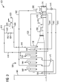
- Fig. 2 illustrates a schematic diagram of a CCPP 100 having a SST 600 according to an example.
- the SST 600 may be operated at a rotational speed that is higher than a grid frequency.
- a gearbox 620 may be connected to the SST 600.
- the gearbox 620 may reduce the rotational speed of the SST 600 to the grid frequency.
- the SST 600 may be connected to a main steam turbine 300 via the gearbox 620 after reducing the rotational speed to the grid frequency.
- the SST 600 may not require a separate generator.
- the example of Fig. 2 otherwise corresponds to the example of Fig. 1 .
- Corresponding parts of Fig. 2 are correspondingly numbered, but are not described again with reference to Fig. 2 .
- Fig. 3 illustrates a schematic diagram of a CCPP 100 having a SST 600 according to an example.
- a HRSG 500 may include an additional reheater 530. Exiting steam from the SST 600 may be routed to the additional reheater 530 via an exiting line 640. According to the example, the exiting steam of the SST 600 may be reheated in the additional reheater 530 to increase temperature of the exiting steam. The reheated exiting steam of the SST 600 may be transferred to a main steam turbine 300 via a HP steam line 522. The illustrated example of Fig. 3 may increase efficiency of the main steam turbine 300. The example of Fig. 3 otherwise corresponds to the example of Fig. 1 . Corresponding parts of Fig. 3 are correspondingly numbered, but are not described again with reference to Fig. 3 .
- Fig. 4 illustrates a schematic flow diagram of a CCPP 100 having a SST 600 according to an alternative example.
- a HP steam system 520 of a HRSG 500 comprises a supercritical HP steam system 524 that may generate supercritical steam.
- the HP steam system 520 further comprises a subcritical HP steam system 526 that may generate subcritical HP steam.
- the supercritical steam may be fed to a SST 600 via a supercritical steam line 610.
- exiting steam from the SST 600 may be mixed with the subcritical HP steam via an exiting line 640 to generate a HP steam mixture.
- the HP steam mixture may be fed to the main steam turbine 300 via a HP steam line 522.
- the example of Fig. 4 otherwise corresponds to the example of Fig. 1 .
- Corresponding parts of Fig. 4 are correspondingly numbered, but are not described again with reference to Fig. 4 .
- Fig. 5 illustrates a schematic flow diagram of a CCPP 100 having a SST 600 according to an example.
- a HRSG 500 may include an additional reheater 530.
- a HP steam system 520 of a HRSG 500 comprises a supercritical HP steam system 524 that may generate supercritical steam.
- the HP steam system 520 further comprises a subcritical HP steam system 526 that may generate subcritical HP steam.
- the supercritical steam generated by the supercritical HP steam system 524 may be fed to a SST 600 via a supercritical steam line 610.
- exiting steam from the SST 600 may be mixed with the subcritical HP steam via an exiting line 640 to generate a HP steam mixture.
- the HP steam mixture may be reheated in the additional reheater 530 to increase temperature of the HP steam mixture.
- the reheated HP steam mixture may be transferred to a main steam turbine 300 via a HP steam line 522.
- the example of Fig. 5 otherwise corresponds to the example of Fig. 4 .
- Corresponding parts of Fig. 5 are correspondingly numbered, but are not described again with reference to Fig. 5 .
- a CCPP 100 may be in a single shaft configuration, or in a multi-shaft configuration.
- the illustrated examples of a CCPP 100 in Fig. 1 to Fig. 5 are in a single shaft configuration. Similar examples may be implemented in a multi-shaft configuration, where a main steam turbine 300 and a gas turbine 200 may be connected to separate generators.
- Fig. 6 illustrates a schematic flow diagram of a multi-shaft CCPP 100 having a SST 600 according to an example.
- a gas turbine 200 may be connected to a gas turbine generator 220.
- a main steam turbine 300 may be connected to a main steam turbine generator 320.
- a SST 600 may be operated at a rotational speed that is higher than a grid frequency.
- the SST 600 may be connected to a gearbox 620.
- the gearbox 620 may reduce a rotational speed of the SST 600 that is higher than a grid frequency to the grid frequency.
- the combined cycle power plant may include a supercritical steam turbine generator 630.
- the SST 600 may be connected to the supercritical steam turbine generator 630 via the gearbox 620 to generate power output after reducing the rotational speed to the grid frequency.
- the supercritical steam turbine generator 630 may be arranged at a location for easy installation.
- the SST 600 may be arranged at a location that is close to a HRSG 500 to reduce high energy piping length.
- the example of Fig. 6 otherwise corresponds to the example of Fig. 1 .
- Corresponding parts of Fig. 6 are correspondingly numbered, but are not described again with reference to Fig. 6 .
- Fig. 7 illustrates a schematic flow diagram of a multi-shaft CCPP 100 having a SST 600 according to an example.
- a gas turbine 200 may be connected to a gas turbine generator 220.
- a main steam turbine 300 may be connected to a main steam turbine generator 320.
- a SST 600 may be operated at a rotational speed that is higher than a grid frequency.
- the SST 600 may be connected to a gearbox 620.
- the gearbox 620 may reduce the rotational speed of the SST 600 that is higher than a grid frequency to the grid frequency.
- Fig. 7 illustrates a schematic flow diagram of a multi-shaft CCPP 100 having a SST 600 according to an example.
- a gas turbine 200 may be connected to a gas turbine generator 220.
- a main steam turbine 300 may be connected to a main steam turbine generator 320.
- a SST 600 may be operated at a rotational speed that is higher than a grid frequency.
- the SST 600 may be connected to
- the SST 600 may be connected to a main steam turbine 300 via the gearbox 620 after reducing the rotational speed to the grid frequency. According to the example as illustrated in Fig. 7 , the SST 600 may not require a separate generator.
- the example of Fig. 7 otherwise corresponds to the example of Fig. 2 . Corresponding parts of Fig. 7 are correspondingly numbered, but are not described again with reference to Fig. 7 .
- the disclosed examples may include a separate SST 600 and a main steam turbine 300.
- the separate SST 600 may be operated at a rotational speed that is much higher than a grid frequency.
- the rotational speed of the SST 600 may be reduced to a grid frequency by a gearbox 620.
- the disclosed examples may address limitation of a power plant efficiency improvement of a single steam turboset.
- a supercritical section, a high pressure section, an intermediate pressure, and a low pressure section may be all operated at the same speed at a grid frequency. This may impact plant efficiency improvement due to effects of the supercritical steam.
- high pressure of the supercritical steam may increase shaft seal leakage losses.
- High pressure of the supercritical steam may reduce flow volume resulting in low turbine efficiency.
- the disclosed examples comprise a separate supercritical steam turbine and a main turbine. The disclosed examples may allow optimizing steam parameters to individual needs of each steam turbine section.
- Fig. 8 a graphic representation of two operation designs for the CCPP 100 operated at a base load and a part load are provided.
- the two operation designs of Fig. 8 illustrate a subcritical operation design pressure and a supercritical operation design pressure, where the SST 600 may be operated at supercritical pressures.
- the part load operation may be between 50 to 70 percent of the CCPP 100 base load operation.
- the methods for improving efficiency described herein is applicable to percentages lower or higher than the 50 to 70 percent described for exemplary purposes.
- This subcritical operation demonstrates a lower steam cycle efficiency, as a maximum reversible efficiency of the based load operation 810 drops from about 0.435 to about 0.41 (at 1000 *0,0689475728 bar), which is the lowest maximum reversible efficiency of the part load operation 820, which includes a range between 0.41-0.425.
- a part load operation 920 for the supercritical base load operation 910 may be within the range of 1800 *0,0689475728 bar to 3000 *0,0689475728 bar. As shown in Fig.
- the maximum reversible efficiency for the supercritical base load operation 910 may be approximately 0.45, which drops in the part load operation 920 to about 0.43 maximum reversible efficiency (at 1800 *0,0689475728 bar), which is the lowest maximum reversible efficiency of the part load operation 920, which includes a range between about 0.43-0.445.
- the supercritical base load operation demonstrates higher steam plant efficiency, as compared to the subcritical operation, as the second CCPP operation of Fig. 8 , shows, e.g., a delta of about 0.005 with the base load operation 910 at about 4000 *0,0689475728 bar and the part load 920 at about 3000 *0,0689475728 bar.
- the maximum reversible efficiency of the part load operation 920 is closer to the maximum reversible efficiency of the base load operation 910, hereby improving plant efficiency both at part load and base load, as any penalty resulting from a part load operation decreases with the implementation of the higher pressure (supercritical) base load operation design.
- the method 1000 includes the step of: initiating a base load pressure at a supercritical steam level to reduce the efficiency impact of a part load operation (1010).
- the supercritical steam level may include a supercritical pressure level of about 4000 *0,0689475728 bar.
- the base load operation is initiated at a supercritical pressure level, i.e., at a level above a critical pressure level, e.g., the base load operation 910 at 4000 *0,0689475728 bar in Fig. 8 .
- the base load operation 910 at 4000 *0,0689475728 bar may have a part load operation between 1800 *0,0689475728 bar and 3000 *0,0689475728 bar.
- the supercritical base load pressure results in a higher steam cycle efficiency, as the maximum reversible efficiency of part load operation 920 is closer or proximate to the maximum reversible efficiency of base load operation 910, e.g., when the part load operation is at about 3000 *0,0689475728 bar and the base load operation is at about 4000 *0,0689475728 bar, as the part load penalty decreases with the supercritical pressure base load operation.
- the improved part load operation efficiency is further illustrated by the curved lines of Fig. 8 , as the curved lines gradually flatten as the pressure increases to supercritical, demonstrating a lesser penalty in the part load operation during a supercritical cycle.
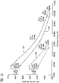
- Fig. 10 illustrates an improvement in the heat rate improvement resulting in a 2x1 and 3x1 combined cycle power plant operation using the supercritical base load operation described herein, as compared to the subcritical operation.
- the net heat rate in the supercritical operation 1100 in the 3x1 CCPP is improved as compared to the subcritical operation 1150.
- the net heat rate in the supercritical operation 1200 in the 2x1 CCPP is improved as compared to the subcritical operation 1250.
Landscapes
- Engineering & Computer Science (AREA)
- Chemical & Material Sciences (AREA)
- Combustion & Propulsion (AREA)
- Mechanical Engineering (AREA)
- General Engineering & Computer Science (AREA)
- Engine Equipment That Uses Special Cycles (AREA)
- Control Of Turbines (AREA)
Claims (11)
- Verfahren zum Betrieb eines Kombikraftwerks (CCPP) (100), das aus einer Gasturbine (200), einem Wärmerückgewinnungsdampfgenerator (500), der sich nachgeordnet zu der Gasturbine (200) befindet, mindestens einer Dampfturbine (300), die einen Niederdruck-Dampfturbinenabschnitt, einen Mitteldruck-Dampfturbinenabschnitt und einen Hochdruck-Dampfturbinenabschnitt umfasst, und einer separaten überkritischen Dampfturbine (600) besteht, umfassend den Schritt:Initiieren eines Grundlastbetriebs (910) des CCPPs mit einem überkritischen Druck mittels überkritischen Dampfes von der Dampfturbine (300);Expandieren des überkritischen Dampfes und Generieren von Austrittsdampf mit einem unterkritischen Druck mittels der überkritischen Dampfturbine (600);Einbringen des Austrittsdampfes mit dem unterkritischen Druck in den Hochdruck-Dampfturbinenabschnitt der Hauptdampfturbine (300); undBetreiben des CCPPs in einem Teillastbetrieb auf einem unterkritischen Druckniveau.
- Verfahren nach Anspruch 1, wobei der überkritische Druck etwa 4000 * 0,0689475728 bar beträgt, was zu einem Teillastbetrieb zwischen 1800 und 3000 * 0,0689475728 bar führt.
- Verfahren nach Anspruch 1, wobei der Teillastbetrieb einen maximalen reversiblen Wirkungsgrad von etwa 0,43 hat, wenn der Teillastbetrieb etwa 1800 *0,0689475728 bar ist.
- Verfahren nach Anspruch 1, wobei der Teillastbetrieb einen maximalen reversiblen Wirkungsgrad von etwa 0,445 hat, wenn die Teillast mit etwa 3000 *0,0689475728 bar arbeitet.
- Verfahren nach Anspruch 1, wobei das CCPP eine zweite Dampfturbine umfasst, und wobei ein zweiter Grundlastbetrieb (810) des CCPPs mit einem unterkritischen Druck mittels der zweiten Dampfturbine arbeitet.
- Verfahren nach Anspruch 5, wobei der unterkritische Druck etwa 2200 * 0,0689475728 bar beträgt, und wobei ein zweiter Teillastbetrieb (820) entsprechend dem zweiten Grundlastbetrieb zwischen 1000 und 1600 *0,0689475728 bar arbeitet.
- Verfahren nach Anspruch 6, wobei Delta-Werte des überkritischen Grundlastbetriebs und entsprechenden Teillastbetriebs unter Delta-Werten des unterkritischen zweiten Grundlastbetriebs und entsprechenden zweiten Teillastbetriebs liegen und die Delta-Werte des überkritischen Grundlastbetriebs eine Verbesserung des Teillastwirkungsgrads angeben.
- Verfahren nach einem der vorhergehenden Ansprüche, wobei der Wärmerückgewinnungs-Dampfgenerator (500) ein Niederdruckdampfsystem (560), ein Mitteldruckdampfsystem (540) und ein Hochdruckdampfsystem (520) umfasst, und wobei das Verfahren des Weiteren die Schritte umfasst:Generieren von Leistungsabgabe aus dem Gasturbinengenerator;Generieren von Niederdruckdampf mittels des Niederdruckdampfsystems (560) durch Extrahieren von Energie aus Abgas der Gasturbine (200);Generieren von Mitteldruckdampf mittels des Mitteldruckdampfsystems (540) durch Extrahieren von Energie aus dem Abgas;Generieren von überkritischem Dampf mittels des Hochdruckdampfsystems (520) durch Extrahieren von Energie aus dem Abgas;Überführen des überkritischen Dampfes zu der überkritischen Dampfturbine (600); undBetreiben der mindestens einen Dampfturbine (300), um Leistungsabgabe aus dem Austrittsdampf, dem Mitteldruckdampf und dem Niederdruckdampf zu generieren.
- Verfahren nach einem der vorhergehenden Ansprüche, des Weiteren umfassend Betreiben der überkritischen Dampfturbine (600) mit einer Drehzahl, die höher als eine Netzfrequenz ist.
- Verfahren nach einem der vorhergehenden Ansprüche, des Weiteren umfassend:Generieren eines unterkritischen Hochdruckdampfes in dem Hochdruckdampfsystem (520),Mischen des unterkritischen Hochdruckdampfes mit dem Austrittsdampf, um eine Hochdruckdampfmischung zu generieren, undÜberführen der Hochdruckdampfmischung in die mindestens eine Dampfturbine (300).
- Verfahren nach Anspruch 10, des Weiteren umfassend:erneutes Erhitzen der Hochdruckdampfmischung in dem Wärmerückgewinnungsdampfgenerator (500),Überführen der erneut erhitzten Hochdruckdampfmischung in die Hochdruckdampfturbine (300).
Applications Claiming Priority (2)
| Application Number | Priority Date | Filing Date | Title |
|---|---|---|---|
| US201562119886P | 2015-02-24 | 2015-02-24 | |
| PCT/US2016/016068 WO2016137677A1 (en) | 2015-02-24 | 2016-02-02 | Methods for operating a combined cycle power plant and improving part load efficiency |
Publications (2)
| Publication Number | Publication Date |
|---|---|
| EP3262286A1 EP3262286A1 (de) | 2018-01-03 |
| EP3262286B1 true EP3262286B1 (de) | 2022-08-24 |
Family
ID=55361990
Family Applications (2)
| Application Number | Title | Priority Date | Filing Date |
|---|---|---|---|
| EP16707263.6A Active EP3262284B1 (de) | 2015-02-24 | 2016-01-25 | Kombikraftwerk mit überkritischer dampfturbine |
| EP16705003.8A Active EP3262286B1 (de) | 2015-02-24 | 2016-02-02 | Verfahren zum betrieb eines kombikraftwerks und verbesserung des teillastwirkungsgrads |
Family Applications Before (1)
| Application Number | Title | Priority Date | Filing Date |
|---|---|---|---|
| EP16707263.6A Active EP3262284B1 (de) | 2015-02-24 | 2016-01-25 | Kombikraftwerk mit überkritischer dampfturbine |
Country Status (3)
| Country | Link |
|---|---|
| US (2) | US10316700B2 (de) |
| EP (2) | EP3262284B1 (de) |
| WO (2) | WO2016137620A1 (de) |
Families Citing this family (1)
| Publication number | Priority date | Publication date | Assignee | Title |
|---|---|---|---|---|
| WO2016137620A1 (en) * | 2015-02-24 | 2016-09-01 | Siemens Aktiengesellschaft | Combined cycle power plant having supercritical steam turbine |
Family Cites Families (24)
| Publication number | Priority date | Publication date | Assignee | Title |
|---|---|---|---|---|
| GB575812A (en) * | 1942-12-12 | 1946-03-06 | Bbc Brown Boveri & Cie | Ultra-high temperature turbine plant |
| CH520265A (de) | 1970-03-17 | 1972-03-15 | Polska Akademia Nauk Inst Masz | Verfahren zur Wirkungsgraderhöhung des Dampf-Kreisprozesses mit einer Dampfturbine für überkritische Parameter |
| WO1986005234A1 (fr) * | 1985-03-15 | 1986-09-12 | Tch Thermo-Consulting-Heidelberg Gmbh | Installation mixte de turbines a vapeur et a gaz |
| DE3731627A1 (de) * | 1987-09-19 | 1989-03-30 | Klaus Prof Dr Ing Dr In Knizia | Verfahren zur leistungsregelung eines kohlekombiblocks mit integrierter kohlevergasung und nach dem verfahren betriebenes kohlekraftwerk |
| DE4434526C1 (de) * | 1994-09-27 | 1996-04-04 | Siemens Ag | Verfahren zum Betreiben einer Gas- und Dampfturbinenanlage sowie danach arbeitende Anlage |
| US6230480B1 (en) * | 1998-08-31 | 2001-05-15 | Rollins, Iii William Scott | High power density combined cycle power plant |
| DE10001995A1 (de) * | 2000-01-19 | 2001-07-26 | Alstom Power Schweiz Ag Baden | Verfahren zur Einstellung bzw. Regelung der Dampftemperatur des Frischdampfes und/oder Zwischenüberhitzerdampfers in einem Verbundkraftwerk sowie Verbundkraftwerk zur Durchführung des Verfahrens |
| DE10056231B4 (de) * | 2000-11-13 | 2012-02-23 | Alstom Technology Ltd. | Verfahren zum Betrieb eines Kombikraftwerks |
| EP1262638A1 (de) * | 2001-05-31 | 2002-12-04 | Siemens Aktiengesellschaft | Vorrichtung zur Kühlmittelkühlung einer Gasturbine und Gas- und Dampfturbinenanlage mit einer derartigen Vorrichtung |
| US6895740B2 (en) * | 2003-01-21 | 2005-05-24 | Donald C. Erickson | Steam ammonia power cycle |
| US6820428B2 (en) | 2003-01-30 | 2004-11-23 | Wylie Inventions Company, Inc. | Supercritical combined cycle for generating electric power |
| EP1775430A1 (de) * | 2005-10-17 | 2007-04-18 | Siemens Aktiengesellschaft | Dampfkraftwerk sowie Verfahren zum Nachrüsten eines Dampfkraftwerks |
| US20090009011A1 (en) * | 2006-03-03 | 2009-01-08 | Jonathan Sidney Edelson | Motor using magnetic normal force |
| US7874162B2 (en) * | 2007-10-04 | 2011-01-25 | General Electric Company | Supercritical steam combined cycle and method |
| DE112009000663B4 (de) * | 2008-03-25 | 2022-11-03 | General Electric Technology Gmbh | Verfahren zum betrieb einer kraftwerksanlage |
| EP2213847A1 (de) * | 2008-09-24 | 2010-08-04 | Siemens Aktiengesellschaft | Dampfkraftanlage zur Erzeugung elektrischer Energie |
| US8839621B2 (en) * | 2009-08-23 | 2014-09-23 | Hybrid Power Llc | Hybrid power plant |
| EP2305364A1 (de) * | 2009-09-29 | 2011-04-06 | Alstom Technology Ltd | Kraftwerksanlage zur CO2-Erfassung |
| US9429044B2 (en) * | 2012-01-13 | 2016-08-30 | Alstom Technology Ltd | Supercritical heat recovery steam generator reheater and supercritical evaporator arrangement |
| EP2762689B1 (de) * | 2013-02-05 | 2017-06-07 | General Electric Technology GmbH | Dampfkraftanlage mit einer zweiten Niederdruckturbine und einem zusätzlichen Kondensierungssystem und Verfahren zum Betrieb einer solchen Dampfkraftanlage |
| EP2811119A1 (de) * | 2013-06-06 | 2014-12-10 | Siemens Aktiengesellschaft | Verfahren zum Testen eines Überdrehzahlschutzes einer GuD-Einwellenanlage |
| US9500103B2 (en) * | 2013-08-22 | 2016-11-22 | General Electric Company | Duct fired combined cycle system |
| DE102013225543B3 (de) * | 2013-12-11 | 2015-02-12 | Currenta Gmbh & Co.Ohg | Dampfspeicherung mit Latentwärmespeicher und Dampf-Thermokompressor |
| WO2016137620A1 (en) * | 2015-02-24 | 2016-09-01 | Siemens Aktiengesellschaft | Combined cycle power plant having supercritical steam turbine |
-
2016
- 2016-01-25 WO PCT/US2016/014675 patent/WO2016137620A1/en not_active Ceased
- 2016-01-25 US US15/549,555 patent/US10316700B2/en active Active
- 2016-01-25 EP EP16707263.6A patent/EP3262284B1/de active Active
- 2016-02-02 WO PCT/US2016/016068 patent/WO2016137677A1/en not_active Ceased
- 2016-02-02 EP EP16705003.8A patent/EP3262286B1/de active Active
- 2016-02-02 US US15/551,942 patent/US10280809B2/en active Active
Also Published As
| Publication number | Publication date |
|---|---|
| US20180030859A1 (en) | 2018-02-01 |
| WO2016137677A1 (en) | 2016-09-01 |
| US20180051596A1 (en) | 2018-02-22 |
| EP3262284B1 (de) | 2019-01-02 |
| US10280809B2 (en) | 2019-05-07 |
| EP3262284A1 (de) | 2018-01-03 |
| US10316700B2 (en) | 2019-06-11 |
| EP3262286A1 (de) | 2018-01-03 |
| WO2016137620A1 (en) | 2016-09-01 |
Similar Documents
| Publication | Publication Date | Title |
|---|---|---|
| De Escalona et al. | Part-load analysis of gas turbine & ORC combined cycles | |
| Ohji et al. | Steam turbine cycles and cycle design optimization: The Rankine cycle, thermal power cycles, and IGCC power plants | |
| US8387388B2 (en) | Turbine blade | |
| US20100170218A1 (en) | Method for expanding compressor discharge bleed air | |
| CN106089341B (zh) | 增强多燃气涡轮联合循环装置中冷蒸汽涡轮启动的方法 | |
| JP5860597B2 (ja) | 排熱回収ボイラ配管を予熱するシステム及び方法 | |
| US5850739A (en) | Steam turbine power plant and method of operating same | |
| CN105201575A (zh) | 提高联合循环功率装置的功率的方法和实行该方法的装置 | |
| EP2535533A2 (de) | Asymmetrisches Kombikraftwerk | |
| US9500103B2 (en) | Duct fired combined cycle system | |
| JP2015068314A (ja) | 燃料ガス加熱設備およびコンバインドサイクル発電プラント | |
| CN115217558A (zh) | 气体涡轮热回收系统和方法 | |
| US10808578B2 (en) | Stack energy control in combined cycle power plant using heating surface bypasses | |
| Darwish et al. | Cogeneration power-desalting plants using gas turbine combined cycle | |
| KR101322359B1 (ko) | 가스 및 증기 터빈 시스템의 시동 방법 | |
| US9404395B2 (en) | Selective pressure kettle boiler for rotor air cooling applications | |
| US10280809B2 (en) | Methods for operating a combined cycle power plant and improving part load efficiency | |
| US20140069078A1 (en) | Combined Cycle System with a Water Turbine | |
| Salazar-Pereyra et al. | Thermodynamic analysis of supercritical and subcritical Rankine cycles | |
| EP3318733B1 (de) | Speisewasserbypasssystem für einen dampfüberhitzer | |
| Kosman | Matching of a Gas Turbine and an Upgraded Supercritical Steam Turbine in Off-Design Operation. | |
| JPH05209503A (ja) | 蒸気ドラムを有する複合発電プラント | |
| KR20260004359A (ko) | 열 회수 증기 발생기들에서의 재가열 증기 온도 턴다운 제어를 위한 시스템 | |
| JP2017053324A (ja) | 蒸気加減弁制御装置、発電プラントおよび蒸気加減弁制御方法 |
Legal Events
| Date | Code | Title | Description |
|---|---|---|---|
| STAA | Information on the status of an ep patent application or granted ep patent |
Free format text: STATUS: THE INTERNATIONAL PUBLICATION HAS BEEN MADE |
|
| PUAI | Public reference made under article 153(3) epc to a published international application that has entered the european phase |
Free format text: ORIGINAL CODE: 0009012 |
|
| STAA | Information on the status of an ep patent application or granted ep patent |
Free format text: STATUS: REQUEST FOR EXAMINATION WAS MADE |
|
| 17P | Request for examination filed |
Effective date: 20170817 |
|
| AK | Designated contracting states |
Kind code of ref document: A1 Designated state(s): AL AT BE BG CH CY CZ DE DK EE ES FI FR GB GR HR HU IE IS IT LI LT LU LV MC MK MT NL NO PL PT RO RS SE SI SK SM TR |
|
| AX | Request for extension of the european patent |
Extension state: BA ME |
|
| DAV | Request for validation of the european patent (deleted) | ||
| DAX | Request for extension of the european patent (deleted) | ||
| STAA | Information on the status of an ep patent application or granted ep patent |
Free format text: STATUS: EXAMINATION IS IN PROGRESS |
|
| 17Q | First examination report despatched |
Effective date: 20210323 |
|
| GRAP | Despatch of communication of intention to grant a patent |
Free format text: ORIGINAL CODE: EPIDOSNIGR1 |
|
| STAA | Information on the status of an ep patent application or granted ep patent |
Free format text: STATUS: GRANT OF PATENT IS INTENDED |
|
| INTG | Intention to grant announced |
Effective date: 20220412 |
|
| GRAS | Grant fee paid |
Free format text: ORIGINAL CODE: EPIDOSNIGR3 |
|
| GRAA | (expected) grant |
Free format text: ORIGINAL CODE: 0009210 |
|
| STAA | Information on the status of an ep patent application or granted ep patent |
Free format text: STATUS: THE PATENT HAS BEEN GRANTED |
|
| AK | Designated contracting states |
Kind code of ref document: B1 Designated state(s): AL AT BE BG CH CY CZ DE DK EE ES FI FR GB GR HR HU IE IS IT LI LT LU LV MC MK MT NL NO PL PT RO RS SE SI SK SM TR |
|
| REG | Reference to a national code |
Ref country code: CH Ref legal event code: EP |
|
| REG | Reference to a national code |
Ref country code: DE Ref legal event code: R096 Ref document number: 602016074463 Country of ref document: DE |
|
| REG | Reference to a national code |
Ref country code: IE Ref legal event code: FG4D |
|
| REG | Reference to a national code |
Ref country code: AT Ref legal event code: REF Ref document number: 1513779 Country of ref document: AT Kind code of ref document: T Effective date: 20220915 |
|
| REG | Reference to a national code |
Ref country code: LT Ref legal event code: MG9D |
|
| REG | Reference to a national code |
Ref country code: NL Ref legal event code: MP Effective date: 20220824 |
|
| PG25 | Lapsed in a contracting state [announced via postgrant information from national office to epo] |
Ref country code: SE Free format text: LAPSE BECAUSE OF FAILURE TO SUBMIT A TRANSLATION OF THE DESCRIPTION OR TO PAY THE FEE WITHIN THE PRESCRIBED TIME-LIMIT Effective date: 20220824 Ref country code: RS Free format text: LAPSE BECAUSE OF FAILURE TO SUBMIT A TRANSLATION OF THE DESCRIPTION OR TO PAY THE FEE WITHIN THE PRESCRIBED TIME-LIMIT Effective date: 20220824 Ref country code: PT Free format text: LAPSE BECAUSE OF FAILURE TO SUBMIT A TRANSLATION OF THE DESCRIPTION OR TO PAY THE FEE WITHIN THE PRESCRIBED TIME-LIMIT Effective date: 20221226 Ref country code: NO Free format text: LAPSE BECAUSE OF FAILURE TO SUBMIT A TRANSLATION OF THE DESCRIPTION OR TO PAY THE FEE WITHIN THE PRESCRIBED TIME-LIMIT Effective date: 20221124 Ref country code: NL Free format text: LAPSE BECAUSE OF FAILURE TO SUBMIT A TRANSLATION OF THE DESCRIPTION OR TO PAY THE FEE WITHIN THE PRESCRIBED TIME-LIMIT Effective date: 20220824 Ref country code: LV Free format text: LAPSE BECAUSE OF FAILURE TO SUBMIT A TRANSLATION OF THE DESCRIPTION OR TO PAY THE FEE WITHIN THE PRESCRIBED TIME-LIMIT Effective date: 20220824 Ref country code: LT Free format text: LAPSE BECAUSE OF FAILURE TO SUBMIT A TRANSLATION OF THE DESCRIPTION OR TO PAY THE FEE WITHIN THE PRESCRIBED TIME-LIMIT Effective date: 20220824 Ref country code: FI Free format text: LAPSE BECAUSE OF FAILURE TO SUBMIT A TRANSLATION OF THE DESCRIPTION OR TO PAY THE FEE WITHIN THE PRESCRIBED TIME-LIMIT Effective date: 20220824 Ref country code: ES Free format text: LAPSE BECAUSE OF FAILURE TO SUBMIT A TRANSLATION OF THE DESCRIPTION OR TO PAY THE FEE WITHIN THE PRESCRIBED TIME-LIMIT Effective date: 20220824 |
|
| REG | Reference to a national code |
Ref country code: AT Ref legal event code: MK05 Ref document number: 1513779 Country of ref document: AT Kind code of ref document: T Effective date: 20220824 |
|
| PG25 | Lapsed in a contracting state [announced via postgrant information from national office to epo] |
Ref country code: PL Free format text: LAPSE BECAUSE OF FAILURE TO SUBMIT A TRANSLATION OF THE DESCRIPTION OR TO PAY THE FEE WITHIN THE PRESCRIBED TIME-LIMIT Effective date: 20220824 Ref country code: IS Free format text: LAPSE BECAUSE OF FAILURE TO SUBMIT A TRANSLATION OF THE DESCRIPTION OR TO PAY THE FEE WITHIN THE PRESCRIBED TIME-LIMIT Effective date: 20221224 Ref country code: HR Free format text: LAPSE BECAUSE OF FAILURE TO SUBMIT A TRANSLATION OF THE DESCRIPTION OR TO PAY THE FEE WITHIN THE PRESCRIBED TIME-LIMIT Effective date: 20220824 Ref country code: GR Free format text: LAPSE BECAUSE OF FAILURE TO SUBMIT A TRANSLATION OF THE DESCRIPTION OR TO PAY THE FEE WITHIN THE PRESCRIBED TIME-LIMIT Effective date: 20221125 |
|
| PG25 | Lapsed in a contracting state [announced via postgrant information from national office to epo] |
Ref country code: SM Free format text: LAPSE BECAUSE OF FAILURE TO SUBMIT A TRANSLATION OF THE DESCRIPTION OR TO PAY THE FEE WITHIN THE PRESCRIBED TIME-LIMIT Effective date: 20220824 Ref country code: RO Free format text: LAPSE BECAUSE OF FAILURE TO SUBMIT A TRANSLATION OF THE DESCRIPTION OR TO PAY THE FEE WITHIN THE PRESCRIBED TIME-LIMIT Effective date: 20220824 Ref country code: DK Free format text: LAPSE BECAUSE OF FAILURE TO SUBMIT A TRANSLATION OF THE DESCRIPTION OR TO PAY THE FEE WITHIN THE PRESCRIBED TIME-LIMIT Effective date: 20220824 Ref country code: CZ Free format text: LAPSE BECAUSE OF FAILURE TO SUBMIT A TRANSLATION OF THE DESCRIPTION OR TO PAY THE FEE WITHIN THE PRESCRIBED TIME-LIMIT Effective date: 20220824 Ref country code: AT Free format text: LAPSE BECAUSE OF FAILURE TO SUBMIT A TRANSLATION OF THE DESCRIPTION OR TO PAY THE FEE WITHIN THE PRESCRIBED TIME-LIMIT Effective date: 20220824 |
|
| REG | Reference to a national code |
Ref country code: DE Ref legal event code: R097 Ref document number: 602016074463 Country of ref document: DE |
|
| PG25 | Lapsed in a contracting state [announced via postgrant information from national office to epo] |
Ref country code: SK Free format text: LAPSE BECAUSE OF FAILURE TO SUBMIT A TRANSLATION OF THE DESCRIPTION OR TO PAY THE FEE WITHIN THE PRESCRIBED TIME-LIMIT Effective date: 20220824 Ref country code: EE Free format text: LAPSE BECAUSE OF FAILURE TO SUBMIT A TRANSLATION OF THE DESCRIPTION OR TO PAY THE FEE WITHIN THE PRESCRIBED TIME-LIMIT Effective date: 20220824 |
|
| PG25 | Lapsed in a contracting state [announced via postgrant information from national office to epo] |
Ref country code: AL Free format text: LAPSE BECAUSE OF FAILURE TO SUBMIT A TRANSLATION OF THE DESCRIPTION OR TO PAY THE FEE WITHIN THE PRESCRIBED TIME-LIMIT Effective date: 20220824 |
|
| PLBE | No opposition filed within time limit |
Free format text: ORIGINAL CODE: 0009261 |
|
| STAA | Information on the status of an ep patent application or granted ep patent |
Free format text: STATUS: NO OPPOSITION FILED WITHIN TIME LIMIT |
|
| 26N | No opposition filed |
Effective date: 20230525 |
|
| PG25 | Lapsed in a contracting state [announced via postgrant information from national office to epo] |
Ref country code: SI Free format text: LAPSE BECAUSE OF FAILURE TO SUBMIT A TRANSLATION OF THE DESCRIPTION OR TO PAY THE FEE WITHIN THE PRESCRIBED TIME-LIMIT Effective date: 20220824 |
|
| PG25 | Lapsed in a contracting state [announced via postgrant information from national office to epo] |
Ref country code: MC Free format text: LAPSE BECAUSE OF FAILURE TO SUBMIT A TRANSLATION OF THE DESCRIPTION OR TO PAY THE FEE WITHIN THE PRESCRIBED TIME-LIMIT Effective date: 20220824 |
|
| REG | Reference to a national code |
Ref country code: CH Ref legal event code: PL |
|
| REG | Reference to a national code |
Ref country code: BE Ref legal event code: MM Effective date: 20230228 |
|
| PG25 | Lapsed in a contracting state [announced via postgrant information from national office to epo] |
Ref country code: LU Free format text: LAPSE BECAUSE OF NON-PAYMENT OF DUE FEES Effective date: 20230202 Ref country code: LI Free format text: LAPSE BECAUSE OF NON-PAYMENT OF DUE FEES Effective date: 20230228 Ref country code: CH Free format text: LAPSE BECAUSE OF NON-PAYMENT OF DUE FEES Effective date: 20230228 |
|
| REG | Reference to a national code |
Ref country code: IE Ref legal event code: MM4A |
|
| PG25 | Lapsed in a contracting state [announced via postgrant information from national office to epo] |
Ref country code: IE Free format text: LAPSE BECAUSE OF NON-PAYMENT OF DUE FEES Effective date: 20230202 |
|
| PG25 | Lapsed in a contracting state [announced via postgrant information from national office to epo] |
Ref country code: BE Free format text: LAPSE BECAUSE OF NON-PAYMENT OF DUE FEES Effective date: 20230228 |
|
| PG25 | Lapsed in a contracting state [announced via postgrant information from national office to epo] |
Ref country code: BG Free format text: LAPSE BECAUSE OF FAILURE TO SUBMIT A TRANSLATION OF THE DESCRIPTION OR TO PAY THE FEE WITHIN THE PRESCRIBED TIME-LIMIT Effective date: 20220824 |
|
| PG25 | Lapsed in a contracting state [announced via postgrant information from national office to epo] |
Ref country code: BG Free format text: LAPSE BECAUSE OF FAILURE TO SUBMIT A TRANSLATION OF THE DESCRIPTION OR TO PAY THE FEE WITHIN THE PRESCRIBED TIME-LIMIT Effective date: 20220824 |
|
| PG25 | Lapsed in a contracting state [announced via postgrant information from national office to epo] |
Ref country code: CY Free format text: LAPSE BECAUSE OF FAILURE TO SUBMIT A TRANSLATION OF THE DESCRIPTION OR TO PAY THE FEE WITHIN THE PRESCRIBED TIME-LIMIT; INVALID AB INITIO Effective date: 20160202 |
|
| PG25 | Lapsed in a contracting state [announced via postgrant information from national office to epo] |
Ref country code: HU Free format text: LAPSE BECAUSE OF FAILURE TO SUBMIT A TRANSLATION OF THE DESCRIPTION OR TO PAY THE FEE WITHIN THE PRESCRIBED TIME-LIMIT; INVALID AB INITIO Effective date: 20160202 |
|
| PG25 | Lapsed in a contracting state [announced via postgrant information from national office to epo] |
Ref country code: TR Free format text: LAPSE BECAUSE OF FAILURE TO SUBMIT A TRANSLATION OF THE DESCRIPTION OR TO PAY THE FEE WITHIN THE PRESCRIBED TIME-LIMIT Effective date: 20220824 |
|
| PGFP | Annual fee paid to national office [announced via postgrant information from national office to epo] |
Ref country code: GB Payment date: 20260223 Year of fee payment: 11 |
|
| PGFP | Annual fee paid to national office [announced via postgrant information from national office to epo] |
Ref country code: DE Payment date: 20260220 Year of fee payment: 11 |
|
| PGFP | Annual fee paid to national office [announced via postgrant information from national office to epo] |
Ref country code: IT Payment date: 20260220 Year of fee payment: 11 |
|
| PGFP | Annual fee paid to national office [announced via postgrant information from national office to epo] |
Ref country code: FR Payment date: 20260224 Year of fee payment: 11 |