EP3261991B9 - Carbon dioxide sequestration with magnesium hydroxide and regeneration of magnesium hydroxide - Google Patents
Carbon dioxide sequestration with magnesium hydroxide and regeneration of magnesium hydroxide Download PDFInfo
- Publication number
- EP3261991B9 EP3261991B9 EP16756203.2A EP16756203A EP3261991B9 EP 3261991 B9 EP3261991 B9 EP 3261991B9 EP 16756203 A EP16756203 A EP 16756203A EP 3261991 B9 EP3261991 B9 EP 3261991B9
- Authority
- EP
- European Patent Office
- Prior art keywords
- reactor
- mgcl
- temperature
- steam
- water
- Prior art date
- Legal status (The legal status is an assumption and is not a legal conclusion. Google has not performed a legal analysis and makes no representation as to the accuracy of the status listed.)
- Active
Links
- VTHJTEIRLNZDEV-UHFFFAOYSA-L magnesium dihydroxide Chemical compound [OH-].[OH-].[Mg+2] VTHJTEIRLNZDEV-UHFFFAOYSA-L 0.000 title claims description 42
- 239000000347 magnesium hydroxide Substances 0.000 title claims description 42
- 229910001862 magnesium hydroxide Inorganic materials 0.000 title claims description 42
- CURLTUGMZLYLDI-UHFFFAOYSA-N Carbon dioxide Chemical compound O=C=O CURLTUGMZLYLDI-UHFFFAOYSA-N 0.000 title description 38
- 229910002092 carbon dioxide Inorganic materials 0.000 title description 30
- 239000001569 carbon dioxide Substances 0.000 title description 7
- 230000008929 regeneration Effects 0.000 title description 2
- 238000011069 regeneration method Methods 0.000 title description 2
- 230000009919 sequestration Effects 0.000 title 1
- TWRXJAOTZQYOKJ-UHFFFAOYSA-L Magnesium chloride Chemical compound [Mg+2].[Cl-].[Cl-] TWRXJAOTZQYOKJ-UHFFFAOYSA-L 0.000 claims description 142
- 229910001629 magnesium chloride Inorganic materials 0.000 claims description 73
- XLYOFNOQVPJJNP-UHFFFAOYSA-N water Substances O XLYOFNOQVPJJNP-UHFFFAOYSA-N 0.000 claims description 49
- 238000000034 method Methods 0.000 claims description 37
- VTYYLEPIZMXCLO-UHFFFAOYSA-L Calcium carbonate Chemical compound [Ca+2].[O-]C([O-])=O VTYYLEPIZMXCLO-UHFFFAOYSA-L 0.000 claims description 30
- UXVMQQNJUSDDNG-UHFFFAOYSA-L Calcium chloride Chemical compound [Cl-].[Cl-].[Ca+2] UXVMQQNJUSDDNG-UHFFFAOYSA-L 0.000 claims description 24
- 239000001110 calcium chloride Substances 0.000 claims description 24
- 229910001628 calcium chloride Inorganic materials 0.000 claims description 24
- 239000000463 material Substances 0.000 claims description 18
- 229910000019 calcium carbonate Inorganic materials 0.000 claims description 15
- 238000006243 chemical reaction Methods 0.000 claims description 13
- 229910019440 Mg(OH) Inorganic materials 0.000 claims description 10
- 239000001095 magnesium carbonate Substances 0.000 claims description 9
- ZLNQQNXFFQJAID-UHFFFAOYSA-L magnesium carbonate Chemical compound [Mg+2].[O-]C([O-])=O ZLNQQNXFFQJAID-UHFFFAOYSA-L 0.000 claims description 9
- 229910000021 magnesium carbonate Inorganic materials 0.000 claims description 9
- 229910052749 magnesium Inorganic materials 0.000 claims description 4
- 239000011777 magnesium Substances 0.000 claims description 4
- 230000001172 regenerating effect Effects 0.000 claims description 4
- FYYHWMGAXLPEAU-UHFFFAOYSA-N Magnesium Chemical compound [Mg] FYYHWMGAXLPEAU-UHFFFAOYSA-N 0.000 claims description 3
- 239000007789 gas Substances 0.000 description 40
- 239000012530 fluid Substances 0.000 description 35
- 238000000354 decomposition reaction Methods 0.000 description 27
- 238000010438 heat treatment Methods 0.000 description 26
- 238000010521 absorption reaction Methods 0.000 description 25
- 239000000047 product Substances 0.000 description 21
- 239000007787 solid Substances 0.000 description 21
- XLYOFNOQVPJJNP-ZSJDYOACSA-N heavy water Substances [2H]O[2H] XLYOFNOQVPJJNP-ZSJDYOACSA-N 0.000 description 9
- 239000007791 liquid phase Substances 0.000 description 8
- 239000000243 solution Substances 0.000 description 8
- 239000007864 aqueous solution Substances 0.000 description 7
- -1 magnesium halide Chemical class 0.000 description 7
- 239000000203 mixture Substances 0.000 description 7
- VNWKTOKETHGBQD-UHFFFAOYSA-N methane Chemical compound C VNWKTOKETHGBQD-UHFFFAOYSA-N 0.000 description 6
- 238000012546 transfer Methods 0.000 description 6
- 239000007788 liquid Substances 0.000 description 5
- UGFAIRIUMAVXCW-UHFFFAOYSA-N Carbon monoxide Chemical compound [O+]#[C-] UGFAIRIUMAVXCW-UHFFFAOYSA-N 0.000 description 4
- RTQCAYKHUMWCEM-UHFFFAOYSA-N [Mg].ClO Chemical compound [Mg].ClO RTQCAYKHUMWCEM-UHFFFAOYSA-N 0.000 description 4
- 239000003546 flue gas Substances 0.000 description 4
- 239000000376 reactant Substances 0.000 description 4
- 239000007790 solid phase Substances 0.000 description 4
- 239000002918 waste heat Substances 0.000 description 4
- BVKZGUZCCUSVTD-UHFFFAOYSA-L Carbonate Chemical compound [O-]C([O-])=O BVKZGUZCCUSVTD-UHFFFAOYSA-L 0.000 description 3
- 238000010586 diagram Methods 0.000 description 3
- 230000000694 effects Effects 0.000 description 3
- 239000003345 natural gas Substances 0.000 description 3
- 238000011084 recovery Methods 0.000 description 3
- 239000011343 solid material Substances 0.000 description 3
- 238000010793 Steam injection (oil industry) Methods 0.000 description 2
- 150000004683 dihydrates Chemical group 0.000 description 2
- 230000005611 electricity Effects 0.000 description 2
- 230000014759 maintenance of location Effects 0.000 description 2
- 238000004064 recycling Methods 0.000 description 2
- 230000000153 supplemental effect Effects 0.000 description 2
- 230000004075 alteration Effects 0.000 description 1
- 239000012159 carrier gas Substances 0.000 description 1
- 239000007795 chemical reaction product Substances 0.000 description 1
- 230000007812 deficiency Effects 0.000 description 1
- 238000011161 development Methods 0.000 description 1
- 230000018109 developmental process Effects 0.000 description 1
- 238000004821 distillation Methods 0.000 description 1
- 238000001035 drying Methods 0.000 description 1
- XLYOFNOQVPJJNP-UHFFFAOYSA-M hydroxide Chemical compound [OH-] XLYOFNOQVPJJNP-UHFFFAOYSA-M 0.000 description 1
- 239000012263 liquid product Substances 0.000 description 1
- DARFZFVWKREYJJ-UHFFFAOYSA-L magnesium dichloride dihydrate Chemical compound O.O.[Mg+2].[Cl-].[Cl-] DARFZFVWKREYJJ-UHFFFAOYSA-L 0.000 description 1
- RNDIHDKIZRODRW-UHFFFAOYSA-L magnesium;chloride;hydroxide Chemical compound [OH-].[Mg+2].[Cl-] RNDIHDKIZRODRW-UHFFFAOYSA-L 0.000 description 1
- 238000012423 maintenance Methods 0.000 description 1
- 238000004519 manufacturing process Methods 0.000 description 1
- 238000002844 melting Methods 0.000 description 1
- 230000008018 melting Effects 0.000 description 1
- 238000012986 modification Methods 0.000 description 1
- 230000004048 modification Effects 0.000 description 1
- 238000010992 reflux Methods 0.000 description 1
- 238000000926 separation method Methods 0.000 description 1
- 239000002002 slurry Substances 0.000 description 1
- 239000007921 spray Substances 0.000 description 1
- 239000007858 starting material Substances 0.000 description 1
- 239000000126 substance Substances 0.000 description 1
Images

Classifications
-
- C—CHEMISTRY; METALLURGY
- C01—INORGANIC CHEMISTRY
- C01F—COMPOUNDS OF THE METALS BERYLLIUM, MAGNESIUM, ALUMINIUM, CALCIUM, STRONTIUM, BARIUM, RADIUM, THORIUM, OR OF THE RARE-EARTH METALS
- C01F5/00—Compounds of magnesium
- C01F5/14—Magnesium hydroxide
-
- B—PERFORMING OPERATIONS; TRANSPORTING
- B01—PHYSICAL OR CHEMICAL PROCESSES OR APPARATUS IN GENERAL
- B01D—SEPARATION
- B01D53/00—Separation of gases or vapours; Recovering vapours of volatile solvents from gases; Chemical or biological purification of waste gases, e.g. engine exhaust gases, smoke, fumes, flue gases, aerosols
- B01D53/34—Chemical or biological purification of waste gases
- B01D53/96—Regeneration, reactivation or recycling of reactants
-
- C—CHEMISTRY; METALLURGY
- C01—INORGANIC CHEMISTRY
- C01F—COMPOUNDS OF THE METALS BERYLLIUM, MAGNESIUM, ALUMINIUM, CALCIUM, STRONTIUM, BARIUM, RADIUM, THORIUM, OR OF THE RARE-EARTH METALS
- C01F5/00—Compounds of magnesium
- C01F5/24—Magnesium carbonates
-
- B—PERFORMING OPERATIONS; TRANSPORTING
- B01—PHYSICAL OR CHEMICAL PROCESSES OR APPARATUS IN GENERAL
- B01D—SEPARATION
- B01D53/00—Separation of gases or vapours; Recovering vapours of volatile solvents from gases; Chemical or biological purification of waste gases, e.g. engine exhaust gases, smoke, fumes, flue gases, aerosols
- B01D53/34—Chemical or biological purification of waste gases
- B01D53/46—Removing components of defined structure
- B01D53/62—Carbon oxides
-
- B—PERFORMING OPERATIONS; TRANSPORTING
- B01—PHYSICAL OR CHEMICAL PROCESSES OR APPARATUS IN GENERAL
- B01D—SEPARATION
- B01D53/00—Separation of gases or vapours; Recovering vapours of volatile solvents from gases; Chemical or biological purification of waste gases, e.g. engine exhaust gases, smoke, fumes, flue gases, aerosols
- B01D53/34—Chemical or biological purification of waste gases
- B01D53/73—After-treatment of removed components
-
- B—PERFORMING OPERATIONS; TRANSPORTING
- B01—PHYSICAL OR CHEMICAL PROCESSES OR APPARATUS IN GENERAL
- B01D—SEPARATION
- B01D53/00—Separation of gases or vapours; Recovering vapours of volatile solvents from gases; Chemical or biological purification of waste gases, e.g. engine exhaust gases, smoke, fumes, flue gases, aerosols
- B01D53/34—Chemical or biological purification of waste gases
- B01D53/74—General processes for purification of waste gases; Apparatus or devices specially adapted therefor
- B01D53/77—Liquid phase processes
- B01D53/78—Liquid phase processes with gas-liquid contact
-
- C—CHEMISTRY; METALLURGY
- C01—INORGANIC CHEMISTRY
- C01B—NON-METALLIC ELEMENTS; COMPOUNDS THEREOF; METALLOIDS OR COMPOUNDS THEREOF NOT COVERED BY SUBCLASS C01C
- C01B7/00—Halogens; Halogen acids
- C01B7/01—Chlorine; Hydrogen chloride
- C01B7/03—Preparation from chlorides
- C01B7/035—Preparation of hydrogen chloride from chlorides
-
- C—CHEMISTRY; METALLURGY
- C01—INORGANIC CHEMISTRY
- C01F—COMPOUNDS OF THE METALS BERYLLIUM, MAGNESIUM, ALUMINIUM, CALCIUM, STRONTIUM, BARIUM, RADIUM, THORIUM, OR OF THE RARE-EARTH METALS
- C01F11/00—Compounds of calcium, strontium, or barium
- C01F11/18—Carbonates
-
- C—CHEMISTRY; METALLURGY
- C01—INORGANIC CHEMISTRY
- C01F—COMPOUNDS OF THE METALS BERYLLIUM, MAGNESIUM, ALUMINIUM, CALCIUM, STRONTIUM, BARIUM, RADIUM, THORIUM, OR OF THE RARE-EARTH METALS
- C01F5/00—Compounds of magnesium
-
- C—CHEMISTRY; METALLURGY
- C01—INORGANIC CHEMISTRY
- C01F—COMPOUNDS OF THE METALS BERYLLIUM, MAGNESIUM, ALUMINIUM, CALCIUM, STRONTIUM, BARIUM, RADIUM, THORIUM, OR OF THE RARE-EARTH METALS
- C01F5/00—Compounds of magnesium
- C01F5/26—Magnesium halides
- C01F5/30—Chlorides
-
- C—CHEMISTRY; METALLURGY
- C01—INORGANIC CHEMISTRY
- C01F—COMPOUNDS OF THE METALS BERYLLIUM, MAGNESIUM, ALUMINIUM, CALCIUM, STRONTIUM, BARIUM, RADIUM, THORIUM, OR OF THE RARE-EARTH METALS
- C01F5/00—Compounds of magnesium
- C01F5/26—Magnesium halides
- C01F5/30—Chlorides
- C01F5/32—Preparation of anhydrous magnesium chloride by chlorinating magnesium compounds
-
- F—MECHANICAL ENGINEERING; LIGHTING; HEATING; WEAPONS; BLASTING
- F23—COMBUSTION APPARATUS; COMBUSTION PROCESSES
- F23J—REMOVAL OR TREATMENT OF COMBUSTION PRODUCTS OR COMBUSTION RESIDUES; FLUES
- F23J15/00—Arrangements of devices for treating smoke or fumes
- F23J15/006—Layout of treatment plant
-
- B—PERFORMING OPERATIONS; TRANSPORTING
- B01—PHYSICAL OR CHEMICAL PROCESSES OR APPARATUS IN GENERAL
- B01D—SEPARATION
- B01D2251/00—Reactants
- B01D2251/40—Alkaline earth metal or magnesium compounds
- B01D2251/402—Alkaline earth metal or magnesium compounds of magnesium
-
- B—PERFORMING OPERATIONS; TRANSPORTING
- B01—PHYSICAL OR CHEMICAL PROCESSES OR APPARATUS IN GENERAL
- B01D—SEPARATION
- B01D2251/00—Reactants
- B01D2251/60—Inorganic bases or salts
- B01D2251/604—Hydroxides
-
- B—PERFORMING OPERATIONS; TRANSPORTING
- B01—PHYSICAL OR CHEMICAL PROCESSES OR APPARATUS IN GENERAL
- B01D—SEPARATION
- B01D2257/00—Components to be removed
- B01D2257/50—Carbon oxides
- B01D2257/504—Carbon dioxide
-
- B—PERFORMING OPERATIONS; TRANSPORTING
- B01—PHYSICAL OR CHEMICAL PROCESSES OR APPARATUS IN GENERAL
- B01D—SEPARATION
- B01D2258/00—Sources of waste gases
- B01D2258/02—Other waste gases
- B01D2258/0283—Flue gases
-
- Y—GENERAL TAGGING OF NEW TECHNOLOGICAL DEVELOPMENTS; GENERAL TAGGING OF CROSS-SECTIONAL TECHNOLOGIES SPANNING OVER SEVERAL SECTIONS OF THE IPC; TECHNICAL SUBJECTS COVERED BY FORMER USPC CROSS-REFERENCE ART COLLECTIONS [XRACs] AND DIGESTS
- Y02—TECHNOLOGIES OR APPLICATIONS FOR MITIGATION OR ADAPTATION AGAINST CLIMATE CHANGE
- Y02C—CAPTURE, STORAGE, SEQUESTRATION OR DISPOSAL OF GREENHOUSE GASES [GHG]
- Y02C20/00—Capture or disposal of greenhouse gases
- Y02C20/40—Capture or disposal of greenhouse gases of CO2
-
- Y—GENERAL TAGGING OF NEW TECHNOLOGICAL DEVELOPMENTS; GENERAL TAGGING OF CROSS-SECTIONAL TECHNOLOGIES SPANNING OVER SEVERAL SECTIONS OF THE IPC; TECHNICAL SUBJECTS COVERED BY FORMER USPC CROSS-REFERENCE ART COLLECTIONS [XRACs] AND DIGESTS
- Y02—TECHNOLOGIES OR APPLICATIONS FOR MITIGATION OR ADAPTATION AGAINST CLIMATE CHANGE
- Y02E—REDUCTION OF GREENHOUSE GAS [GHG] EMISSIONS, RELATED TO ENERGY GENERATION, TRANSMISSION OR DISTRIBUTION
- Y02E20/00—Combustion technologies with mitigation potential
- Y02E20/32—Direct CO2 mitigation
-
- Y—GENERAL TAGGING OF NEW TECHNOLOGICAL DEVELOPMENTS; GENERAL TAGGING OF CROSS-SECTIONAL TECHNOLOGIES SPANNING OVER SEVERAL SECTIONS OF THE IPC; TECHNICAL SUBJECTS COVERED BY FORMER USPC CROSS-REFERENCE ART COLLECTIONS [XRACs] AND DIGESTS
- Y02—TECHNOLOGIES OR APPLICATIONS FOR MITIGATION OR ADAPTATION AGAINST CLIMATE CHANGE
- Y02E—REDUCTION OF GREENHOUSE GAS [GHG] EMISSIONS, RELATED TO ENERGY GENERATION, TRANSMISSION OR DISTRIBUTION
- Y02E60/00—Enabling technologies; Technologies with a potential or indirect contribution to GHG emissions mitigation
- Y02E60/30—Hydrogen technology
- Y02E60/36—Hydrogen production from non-carbon containing sources, e.g. by water electrolysis
-
- Y—GENERAL TAGGING OF NEW TECHNOLOGICAL DEVELOPMENTS; GENERAL TAGGING OF CROSS-SECTIONAL TECHNOLOGIES SPANNING OVER SEVERAL SECTIONS OF THE IPC; TECHNICAL SUBJECTS COVERED BY FORMER USPC CROSS-REFERENCE ART COLLECTIONS [XRACs] AND DIGESTS
- Y02—TECHNOLOGIES OR APPLICATIONS FOR MITIGATION OR ADAPTATION AGAINST CLIMATE CHANGE
- Y02P—CLIMATE CHANGE MITIGATION TECHNOLOGIES IN THE PRODUCTION OR PROCESSING OF GOODS
- Y02P20/00—Technologies relating to chemical industry
- Y02P20/10—Process efficiency
- Y02P20/129—Energy recovery, e.g. by cogeneration, H2recovery or pressure recovery turbines
-
- Y—GENERAL TAGGING OF NEW TECHNOLOGICAL DEVELOPMENTS; GENERAL TAGGING OF CROSS-SECTIONAL TECHNOLOGIES SPANNING OVER SEVERAL SECTIONS OF THE IPC; TECHNICAL SUBJECTS COVERED BY FORMER USPC CROSS-REFERENCE ART COLLECTIONS [XRACs] AND DIGESTS
- Y02—TECHNOLOGIES OR APPLICATIONS FOR MITIGATION OR ADAPTATION AGAINST CLIMATE CHANGE
- Y02P—CLIMATE CHANGE MITIGATION TECHNOLOGIES IN THE PRODUCTION OR PROCESSING OF GOODS
- Y02P20/00—Technologies relating to chemical industry
- Y02P20/151—Reduction of greenhouse gas [GHG] emissions, e.g. CO2
Definitions
- the invention generally concerns methods related to regeneration of magnesium hydroxide from magnesium halide.
- US2013202516 discloses sequestering carbon dioxide comprising: (a) reacting magnesium chloride or its hydrate with water in a first admixture; (b) reacting magnesium chloride hydroxide with a quantity of water and a quantity of magnesium chloride in a second admixture; (c) admixing magnesium hydroxide from the first step (b) product with calcium chloride or its hydrate and carbon dioxide produced in a third admixture; and (d) separating calcium carbonate from the third product mixture.
- the present invention relates to a method of regenerating Mg(OH) 2 and reducing the amount of CO 2 in a gas stream. Described in the following is a system configured to regenerate Mg(OH) 2 and reduce the amount of CO 2 contained in a gas stream through consumption of the Mg(OH) 2 .
- the system can comprise a first decomposition reactor configured to react MgCl 2 containing material with steam to form first reactor products comprising Mg(OH)Cl and HCl; a second decomposition reactor configured to react Mg(OH)Cl from the first decomposition reactor with steam to form HCl and magnesium-containing products comprising mostly Mg(OH) 2 ; and a first absorption reactor configured to form an admixture comprising Mg(OH) 2 from the second decomposition reactor, CO 2 , CaCl 2 , and steam to form products comprising MgCl 2 and CaCO 3 .
- the MgCl 2 containing material fed to the first decomposition reactor can comprise a molar ratio of water to MgCl 2 of less than about 2.5:1.
- the system can further comprise a gaseous feed line configured to pass a gaseous outflow from the second decomposition reactor to the first decomposition reactor, where the gaseous outflow comprises HCl and steam.
- the system can further comprise a second absorption reactor, wherein the first absorption reactor is configured to admix Mg(OH) 2 from the second decomposition reactor with CO 2 contained in the gas stream and form MgCO 3 and H 2 O and wherein the second absorption reactor is configured to admix the MgCO 3 from the first absorption reactor with CaCl 2 and form CaCO 3 and MgCl 2 .
- the first absorption reactor products can be in a liquid phase and a solid phase, and the liquid phase is at least 50% by weight of MgCl 2 .
- the first absorption reactor (or the second absorption reactor if present) can contain a liquid phase comprising a ratio of water to MgCl 2 of less than about 4.5:1 or about 4 to 1.
- a major portion of MgCl 2 in the liquid phase that exits an absorption reactor can be in the form of MgCl 2 tetrahydrate.
- the system can further comprise a solid liquid separator configured to separate at least a portion of the CaCO 3 from the liquid phase.
- the system can include a dryer configured to remove a portion of the water from the liquid phase so the ratio of water to MgCl 2 is about 2 to 1.
- a waste heat recovery and heat transfer system can be utilized to provide the necessary heat to maintain reaction conditions for each system module.
- the present invention is a method of regenerating Mg(OH) 2 in a process that reduces the amount of CO 2 contained in a gas stream comprising
- the method according to the present invention can further comprise passing a gaseous outflow comprising HCl and steam from step (b) (the second admixture) to the reaction of step (a) (the first admixture) to react with the MgCl 2 containing material.
- the MgCl 2 reaction product of step (c) is present in a liquid phase with at least 50% by weight of MgCl 2 .
- the method can further comprise the step or steps of separating at least a portion of the CaCO 3 and a portion of the water from the second step (c) products so that, in a remaining product, the ratio of water to MgCl 2 is about 2 to 1.
- the first step (a) product can comprise greater than 90% by weight of Mg(OH)Cl.
- the first step (b) product can comprise greater than 90% by weight of Mg(OH) 2 .
- the method can comprise recovering waste heat from a gas stream and transferring to the first admixture, the second admixture, and/or the remaining product comprising MgCl 2 dihydrate. In recovering and transferring the waste heat, three or more heating loops can be used.
- Another aspect of the present disclosure is a method for producing magnesium hydroxide from magnesium chloride-containing material comprising: a first stage comprising the steps of introducing said material into a first reactor, passing a steam mixture into the first reactor with the magnesium chloride-containing material at the approximate temperature of 250 to 400 C, to form magnesium hydroxychloride and HCl, a second stage of conveying the magnesium hydroxychloride into a second reactor, introducing therewith steam to form magnesium hydroxide and HCl, where the magnesium chloride-containing material comprises a water to magnesium chloride ratio of about 2: 1.
- a portion of a steam mixture exiting the second reactor can be the steam mixture introduced into the first reactor.
- the magnesium chloride-containing material can substantially comprise magnesium chloride dihydrate. Waste heat can be utilized to provide the heat necessary to form the Mg(OH) 2 .
- an element of a method that "comprises,” “has,” “includes” or “contains” one or more features possesses those one or more features, but is not limited to possessing only those one or more features.
- terms such as “first” and “second” are used only to differentiate structures or features, and not to limit the different structures or features to a particular order.
- a structure that is capable performing a function or that is configured in a certain way is capable or configured in at least that way, but may also be capable or configured in ways that are not listed.
- Any of the present methods can consist of or consist essentially of-rather than comprise/include/contain/have-any of the described elements and/or features and/or steps.
- System 100 is a first embodiment of a system (non-inventive) configured to remove from a gaseous stream using Mg(OH) 2 and to regenerate the Mg(OH) 2 .
- System 100 is configured to absorb carbon dioxide from a gas stream 2 and regenerate at least one of the reactants, e.g., magnesium hydroxide, used in the absorption process.
- reactants e.g., magnesium hydroxide
- System 100 comprises an absorption reactor 10 configured to absorb CO 2 from a gaseous stream; a solid-liquid separator 20 configured to separate carbonate solids from aqueous magnesium chloride; a dryer 30 configured to remove a portion of water from the aqueous magnesium chloride forming magnesium chloride solids; a first decomposition reactor 40 configured to convert the magnesium chloride to magnesium hydroxychloride, and a second decomposition reactor 45 configured to convert the magnesium hydroxychloride to magnesium hydroxide. Also illustrated in system 100 is a plurality of heaters and heating fluid systems to elevate the temperatures of the different reactants.
- gas stream 2 Prior to treating the carbon dioxide containing gas stream 2, the temperature of gas stream 2 may be lowered.
- gas stream 2 can provide process heat that is transferred to different units in the system.
- the process heat can be transferred to one or more of boilers, pre-heaters, reactors, or dryers 30 in the system.
- process heat can be transferred to a recycling heating fluid such as a hot oil system configured to provide indirect heating to the decomposition reactor.
- a recycling heating fluid such as a hot oil system configured to provide indirect heating to the decomposition reactor.
- Process heat can also be used to heat a boiler configured to generate superheated steam for direct steam injection into the decomposition reactor.
- a second recycling heating fluid such as a second hot oil system, can be configured to provide indirect heating to dryer 30 to remove water from the MgCl 2 containing starting material.
- gas stream 2 enters absorption reactor 10 configured to react the CO 2 with CaCl 2 and Mg(OH) 2 via the following overall reactions: CaCl 2 + Mg(OH) 2 + CO 2 ⁇ CaCO 3 + MgCl 2 + H 2 O (1)
- Reactor 10 can be configured to receive CaCl 2 feed 3, gas stream 2, and a Mg(OH) 2 feed.
- Absorption reactor 10 can be configured to operate at temperatures greater than 165 °C, such as between about 170 to 250 °C.
- the operation temperature of reactor 10 can be at least 170, 175, 180, 185, 190, 195, 200, 210, 220, 230, or 240°C.
- the operation temperature of reactor 10 can be between 175 and 185 °C.
- reactor 10 can be configured similar to a distillation column, with a water reflux entering the top of the column and a heat input at the bottom of the column to maintain a bottom liquid product at the operation temperature, such as about 175 °C.
- the reactants can be preheated to the operation temperature prior to introducing into absorption reactor 10.
- a calcium chloride feed 3 is preheated in heater 60 prior to being added to absorption reactor 10.
- a water feed 4 may also be preheated in heater 61.
- heat can be removed from reactor 10 to maintain operation temperature.
- a circulating heating fluid loop (not shown) can be configured to transfer heat from reactor 10 to CaCl 2 feed 5, such as through heater 60.
- a separate circulating heating fluid loop (not shown) can be configured to transfer heat from reactor 10 to water feed 4, such as through heater 61.
- approximately 18.46 MW (63 MMBtu/hr) of process heat (such as from reactor 10) can be needed to heat 0.76 kmol/hr (1,679 lb*mol/hr) of CaCl 2 ⁇ 2H 2 O solids from 25°C to 175°C and melt the solids at its melting point of 175°C, and to heat 0.76 kmol/hr (1,679 lb*mol/hr) of water from 25°C to 100°C, vaporize the water, and superheat the steam to 175°C.
- Calcium chloride can be added to reactor 10 in one of three forms to absorption reactor 10: anhydrous CaCl 2 , CaCl 2 ⁇ 2H 2 O, or CaCl 2 ⁇ 4H 2 O.
- a molar ratio of water to CaCl 2 of about 3:1 or less can be added to the absorption column for every mole of CO 2 that is captured.
- CaCl 2 ⁇ 2H 2 O and water can be fed to absorption reactor 10 to create an equivalent mixture of CaCl 2 ⁇ 3H 2 O (67.2 wt% aqueous CaCl 2 ).
- CaCl 2 feed 3 in dihydrate form can be converted from a solid phase to a liquid phase prior to entering reactor 10.
- Reactor 10 is configured to comprise an outlet for aqueous slurry of CaCO 3 solids in aqueous MgCl 2 and an outlet for gas stream 2 that contains a reduced amount of CO 2 than that inputted into reactor 10.
- Gas stream 2 with the reduced CO 2 concentration can exits absorption reactor 10 and can then pass through gas cooler 72 where heat can be further recovered before gas stream 2 is exhausted to the atmosphere or further processed downstream.
- the heat can be used to pre-heat the reactants, such as CaCl 2 and optionally water.
- the amount of CO 2 in gas stream 2 can be reduced by at least 30%, 40%, 50%, 60%, 70%, 80%, 90%, 95%, 98%, or 99%.
- At least 50 wt% aqueous MgCl 2 can exit the absorption reactor 10 and enter solid-liquid separator 20, which separates the CaCO 3 solids from the aqueous solution.
- a weight percent of aqueous MgCl 2 between 50 to 60% can exit absorption reactor 10 and enter solid-liquid separator 20, such as 51%, 53%, 55%, 57%, or 59% wt MgCl 2 .
- a major portion of MgCl 2 in the aqueous solution can be in the form of MgCl 2 tetrahydrate.
- Water may be added to solid-liquid separator 20 to facilitate the separation of the carbonate solids.
- the amount of water to be added can dilute the solution by less than 30%, 25%, 20%, 15%, 10%, or 5%.
- the hot CaCO 3 solids can be passed through a cooler 70 for energy recovery before being sent to storage.
- the aqueous solution is transferred to dryer 30 to remove water from the solution.
- a sufficient amount of water can be evaporated from the solution so that the ratio of water to MgCl 2 is less than about 2.5:1, or less than about 2 to 1.
- a major portion of the water in the magnesium chloride-containing material exiting dryer 30 can be in the form of MgCl 2 dihydrate.
- the magnesium chloride containing material comprises at least 55%, 60%, 65% 70%, 75% 80%, 85% 90%, 95%, or 98% of MgCl 2 ⁇ 2H 2 O (s).
- the primary reaction in dryer 30 is provided below: MgCl 2 ⁇ 4H 2 O (l) ⁇ MgCl 2 ⁇ 2H 2 O (s) + 2 H 2 O (g) (2)
- heat can be supplied to the vessel to keep the operation temperature at between 150 to 250°C, such as 160, 170, 180, 190, 200, 210, 220, 230, or 240°C.
- the temperature can be kept between 195 and 205°C or 198 and 202°C.
- Dryer 30 is configured such that superheated steam (and potentially some HCl) exits the top of the vessel, while magnesium chloride containing material comprising dihydrate salts moves to first decomposition reactor 40.
- Operation pressures can be at atmospheric pressure.
- the superheated steam produced from dryer 30 can supply at least a portion of the steam required for decomposition reactors 40 and/or 45.
- the aqueous MgCl 2 solution can be pumped through a heater 62 before entering dryer 30 to raise the temperature of the solution to substantially equal to the operation temperatures of dryer 30.
- Heat can be transferred to the solution at heater 62 by a circulating heating fluid loop 83 configured to transfer heat from gas stream 2 to the aqueous solution.
- System 100 can comprise an evaporator 30 that is configured to reduce the water content so that MgCl 2 turns to solid and the solid material can be transferred to first decomposition reactor 40.
- evaporator 30 can comprise a flash drum having a scraper or other agitator configured to facilitate conveyance to solid material.
- a pressurized MgCl 2 solution at the operation temperature can be flashed to atmospheric pressure to remove water from the aqueous solution and produce MgCl 2 ⁇ 2H 2 O solids.
- a portion of the heating fluid in circulating loop 83 may be directed to evaporator 30 to maintain the operation temperatures of evaporator 30.
- System 100 can comprise a dryer 30 that is configured to reduce the water content so that aqueous MgCl 2 turns to solid and the solid material can be transferred to first decomposition reactor 40.
- Dryer 30 can be configured to apply indirect contact heating or direct contact heating using a medium such as air to maintain operation temperatures.
- dryer 30 can be a rotary dryer, a flash dryer, or a spray dryer.
- a portion of the heating fluid in circulating loop 83 may be directed to dryer 30 to maintain the operation temperatures of dryer 30 and may also be directed to blower to heat the drying medium such as air.
- system 100 can comprise a flaker, a crystallizer, or a priller configured to reduce the water content so that the molar ratio is about 2:1 and/or the MgCl 2 is mostly in a dihydrate form and can be transferred to first decomposition reactor 40.
- the heat input needed to raise the temperature of the aqueous solution to an operation temperature of 200°C is approximately 2.05 MW (7 MMBtu/hr).
- the heat input needed to reduce the water content of an aqueous solution where the molar ratio of water is 4:1 is approximately 20.81 MW (71 MMBtu/hr).
- the fluid return temperature can be about 5 to 15°C above the operation temperature, e.g., 210°C, for the fluid leaving dryer 30 or heater 62.
- the fluid supply temperature (e.g., the temperature of the fluid approaching dryer 30 or heater 62) can be about 20 to 30°C above the operation temperature or 10 to 20°C above the return temperature, e.g., 225°C.
- the temperature of gas stream 2 can be a temperature that is at least 30 to 40 above the operation temperature of decomposition reactor 40.
- the temperature of gas stream 2 after transferring heat to loop 83 can be at least 235 °C.
- System 100 comprises reactors configured for a two stage, counter-current flow decomposition reactor to convert MgCl 2 to Mg(OH) 2 .
- reactor 40 is configured for the following reaction to occur: MgCl 2 ⁇ 2H 2 O (s) ⁇ Mg(OH)Cl (s) + HCl (g) + H 2 O (g) (3)
- reactor 45 is configured for the following reaction to occur: Mg(OH)Cl (s) + H 2 O (g) ⁇ Mg(OH) 2 (s) + HCl (g) (4)
- steam can be counter-currently contacted with MgOHCl solids fed from first reactor 40.
- Steam can be generated by a boiler 90 that is heated by gas stream 2.
- steam recycled from the exhaust of reactors 40 and 45 can be mixed with the steam from boiler 90 to feed reactor 45.
- Recycled steam may be heated by a heater 65 to obtain the desired final steam temperature to feed reactor 45.
- Steam is introduced into reactor 45 at a temperature that is substantially the same as the operation temperature of reactor 45 as described below. For example, steam can be introduced into reactor 45 at a temperature between 385°C and 395°C, such as about 390°C.
- the Mg(OH) 2 solids exiting reactor 45 are in equilibrium with the vapor leaving reactor 45.
- the exiting vapor leaving reactor 45 can comprise at least 0.8 mole of HCl for every mole of Mg(OH) 2 produced.
- the exiting vapor leaving reactor 45 can comprise 0.85 mole of HCl, 0.9 mole of HCl, 0.95 mole of HCl, 0.98 mole HCl for ever mole of Mg(OH) 2 produced.
- the rate of counter-flow through reactor 45 is sufficient to keep the partial pressure of HCl low enough so that reaction (5) equilibrium is shifted to the right.
- the counter flow can be 100% superheated steam.
- the counter flow can also comprise superheated steam and an inert carrier gas.
- the partial pressure of HCl can be maintained at a sufficiently low amount by operating the decomposition reaction 45 under vacuum conditions.
- the vapor mixture of superheated steam and HCl leaving reactor 45 is counter-currently contacted with the magnesium chloride material fed from dryer or evaporator 30 comprising MgCl 2 ⁇ 2H 2 O solids.
- the magnesium chloride material fed from dryer or evaporator 30 comprising MgCl 2 ⁇ 2H 2 O solids.
- only a portion of the steam exiting reactor 45 is fed to reactor 40.
- a majority of the vapor exiting reactor 45 can bypass reactor 40 so that additional heat can be recovered in the HCl condenser 76.
- the Mg(OH)Cl solids exiting reactor 40 can be in equilibrium with the vapor leaving reactor 40.
- the exiting vapor leaving reactor 40 can comprise at least an additional 0.8 mole of HCl for every mole ofMgOHCl produced.
- the exiting vapor leaving reactor 40 can comprise an additional 0.85 mole of HCl, 0.9 mole of HCl, 0.95 mole of HCl, 0.98 mole HCl for every mole of MgOHCl produced.
- the rate of counter-flow through reactor 40 is sufficient to keep the partial pressure of HCl low enough to maintain a shift of reaction (4) to the right.
- the operation temperature for reactor 45 can be between 380°C and 500°C, such as about 390, 400, 410, 420, 430, 440, 450, 460, 470, or 490°C.
- the operation temperature for reactor 45 can be between about 385°C and 395°C, such as about 390°C.
- the operation temperature for reactor 40 can be between 250°C and 400°C, such as 260, 270, 280, 290, 300, 310, 320, 330, 340, 350, 360, 370, 380, or 390°C.
- the operation temperature of reactor 40 can be between about 275°C and 285°C, such as about 280°C.
- the steam requirements for the two-stage counter-current configuration can be approximately 3.9 kg/hr (8.6 lb/hr) of steam per 0.45 kg/hr (1 lb/hr) HCl at 390°C for second reactor 45 and 280°C for first reactor 40.
- An output of reactor 40 comprises solid MgOHCl.
- the solid phase output of reactor 40 can be at least 55%, 60%, 65% 70%, 75% 80%, 85% 90%, 95%, 98%, or 99% of MgOHCl.
- An output of reactor 45 comprises solid Mg(OH) 2 .
- the solid phase output of reactor 45 can be at least 55%, 60%, 65% 70%, 75% 80%, 85% 90%, 95%, 98%, or 99% of Mg(OH) 2 .
- heat can be supplied to the decomposition reactors 40, 45 indirectly through a circulating heating fluid loop to keep the decomposition reactor at the desired temperature.
- heating fluid jackets about each reactor 40 and 45 can facilitate maintenance of the operation temperature.
- circulating heating fluid loop 84 is configured to transfer heat from gas stream 2 to reactor 40 and circulating heating fluid loop 85 is configured to transfer heat from gas stream 2 to reactor 45.
- the MgCl 2 containing material exiting dryer 30 can be conveyed through a heater 64 before entering reactor 40 to raise the temperature of the solution to substantially equal to the operation temperatures of reactor 40. While not shown in the one illustrated, a portion of the heating fluid in circulating loop 84 may be directed to heater 64 to heat the MgCl 2 containing material fed to reactor 40.
- the fluid return temperature (e.g., for the heating fluid leaving reactor 45 and heater 65) can be about 5 to 15°C above the operation temperature of reactor 40; e.g., the fluid return temperature can be about 400°C.
- the fluid supply temperature (e.g., the temperature of the fluid approaching reactor 45 and heater 65) can be about 10 to 45°C above the operation temperature or 5 to 25°C above the return temperature; e.g., the fluid supply temperature can be about 415°C.
- the temperature of gas stream 2 can be greater than 500°C or greater than 600°C, e.g., the temperature of a flue gas exhaust stream.
- the temperature of gas stream 2 after transferring heat to loop 85 can be at least 10°C higher than the temperature of the heating fluid approaching reactor 45.
- the fluid return temperature (e.g., the temperature of the heating fluid leaving reactor 40 or heater 64) can be about 5 to 15°C above the operation temperature of reactor 45; e.g., the fluid return temperature can be about 290°C.
- the fluid supply temperature (e.g., the temperature of the fluid approaching reactor 40 or heater 64) can be about 5 to 20°C above the operation temperature or 60 to 100°C above the return temperature; e.g., the fluid supply temperature can be about 355°C.
- the temperature of gas stream 2 can be greater than 500°C or greater than 600°C, e.g., the temperature of a flue gas exhaust stream.
- the temperature of gas stream 2 after transferring heat to loop 85 can be at least 10 degrees higher than the temperature of the heating fluid approaching reactor 40.
- the hot Mg(OH) 2 solids exiting reactor 45 can be passed through a solids product cooler 74 before entering absorption reactor 10, while the vapor product exiting reactor 40 is combined with the vapor bypass 6 around reactor 40.
- the combined vapor stream passes through HCl condenser 76 before being pumped to an HCl product tank.
- System 100 can comprise a gas turbine or be configured to receive gas stream 2 produced from a gas turbine, such as a 60MW gas turbine 95 in the embodiment shown.
- the overall CO 2 capture rate can be greater than 70%, 80%, 90%, 95%, or greater than 99%.
- system 100 can comprise a furnace (not shown) to burn supplemental natural gas, and use heat recovered from the flue gas at the flame temperature to provide additional heat for steam generation within system 100.
- the total enthalpy requirement for the process can be about 51.29 MW (175 MMBtu/hr).
- the heat available from 60 MW turbine exhaust gas is about 42.79 MW (146 MMBtu/hr), leaving an overall deficiency of about 8.5 MW (29 MMBtu/hr) that would be required to achieve 100% CO 2 capture.
- Burning 1,562 Nm 3 /hr @ 0°C (1.4 MMSCFD) of supplemental natural gas in a furnace can provide heat recovery from the flue gas of 13.16 MW (44.9 MMBtu/hr). An additional 4.69 to 4.98 MW (16-17 MMBtu/hr) of enthalpy would be required within system 100 to capture this additional CO 2 . This results in a net enthalpy surplus that could be used to achieve 100% CO 2 capture. If this 1,562 Nm 3 /hr @ 0°C (1.4 MMSCFD) of natural gas were instead fired in a turbine, 5.6 MW of additional electricity could be produced (relative to the 60 MW of electricity produced in the existing turbine).
- Embodiment 200 is a second embodiment of a system (non-inventive) configured to remove from a gaseous stream using Mg(OH) 2 and regenerate the Mg(OH) 2 .
- Embodiment 200 is substantially similar to embodiment 100 described above, except that the decomposition process comprises only a single stage counter flow reactor 48 and circulating heating fluid loop 86 instead of loops 84 and 85.
- the operation temperature of reactor 48 can be between 340°C -360°C, such as 350 °C.
- the superheated steam can be introduced at a temperature substantially the same as the operation temperature.
- FIG. 3 shown therein and designated by reference numeral 300 is an embodiment of a two-stage CO 2 absorption process that can be substituted for the one stage absorption process described above in connection with reactor 10.
- the two-stage process is substantially similar to the conditions described for the one-stage process except that two reactors are used instead of one and a slightly higher molar ratio of water to MgCl 2 is required.
- reactor 12 is configured for the following reaction to occur: Mg(OH) 2 (s) + CO 2 (g) ⁇ MgCO 3 (aq) + H 2 O (l) (5)
- reactor 14 is configured for the following reaction to occur: CaCl 2 (aq) + MgCO 3 (aq) ⁇ CaCO 3 (s) + MgCl 2 (aq) (6)
- the molar ratio of water to MgCO 3 can be about 3.5:1 or about 3:1.
- the molar ratio of water to MgCl 2 can be about 5.5:1 or about 5:1.
Description
- This application claims the benefit of priority to
U.S. Provisional Patent Application Serial No. 62/119,633, filed February 23, 2015 - The invention generally concerns methods related to regeneration of magnesium hydroxide from magnesium halide.
- Considerable domestic and international concern has been increasingly focused on the emission of CO2 into the air. In particular, attention has been focused on the effect of this gas on the retention of solar heat in the atmosphere, producing the "greenhouse effect." Although there is some debate regarding the magnitude of the effect, all would agree there is a benefit to removing CO2 (and other chemicals) from point-emission sources, especially if the cost for doing so were sufficiently small.
- Despite years of development, the task of creating a commercially-viable, environmentally-sensitive process for removing carbon dioxide from an emission source has proven to be a difficult. The methodologies to date have not been altogether satisfactory in this regard, and a significant need exists for the techniques described and claimed in this disclosure.
-
US2013202516 discloses sequestering carbon dioxide comprising: (a) reacting magnesium chloride or its hydrate with water in a first admixture; (b) reacting magnesium chloride hydroxide with a quantity of water and a quantity of magnesium chloride in a second admixture; (c) admixing magnesium hydroxide from the first step (b) product with calcium chloride or its hydrate and carbon dioxide produced in a third admixture; and (d) separating calcium carbonate from the third product mixture. - Throughout the following disclosure the use of the terms "system" and "device" is considered being non-inventive, the present invention relates to a method of regenerating Mg(OH)2 and reducing the amount of CO2 in a gas stream. Described in the following is a system configured to regenerate Mg(OH)2 and reduce the amount of CO2 contained in a gas stream through consumption of the Mg(OH)2. The system can comprise a first decomposition reactor configured to react MgCl2 containing material with steam to form first reactor products comprising Mg(OH)Cl and HCl; a second decomposition reactor configured to react Mg(OH)Cl from the first decomposition reactor with steam to form HCl and magnesium-containing products comprising mostly Mg(OH)2; and a first absorption reactor configured to form an admixture comprising Mg(OH)2 from the second decomposition reactor, CO2, CaCl2, and steam to form products comprising MgCl2 and CaCO3. The MgCl2 containing material fed to the first decomposition reactor can comprise a molar ratio of water to MgCl2 of less than about 2.5:1. The system can further comprise a gaseous feed line configured to pass a gaseous outflow from the second decomposition reactor to the first decomposition reactor, where the gaseous outflow comprises HCl and steam. The system can further comprise a second absorption reactor, wherein the first absorption reactor is configured to admix Mg(OH)2 from the second decomposition reactor with CO2 contained in the gas stream and form MgCO3 and H2O and wherein the second absorption reactor is configured to admix the MgCO3 from the first absorption reactor with CaCl2 and form CaCO3 and MgCl2. The first absorption reactor products can be in a liquid phase and a solid phase, and the liquid phase is at least 50% by weight of MgCl2. The first absorption reactor (or the second absorption reactor if present) can contain a liquid phase comprising a ratio of water to MgCl2 of less than about 4.5:1 or about 4 to 1. A major portion of MgCl2 in the liquid phase that exits an absorption reactor can be in the form of MgCl2 tetrahydrate. The system can further comprise a solid liquid separator configured to separate at least a portion of the CaCO3 from the liquid phase. The system can include a dryer configured to remove a portion of the water from the liquid phase so the ratio of water to MgCl2 is about 2 to 1. A waste heat recovery and heat transfer system can be utilized to provide the necessary heat to maintain reaction conditions for each system module.
- The present invention is a method of regenerating Mg(OH)2 in a process that reduces the amount of CO2 contained in a gas stream comprising
- (a) reacting MgCl2 containing material with steam in a first admixture, preferably at a temperature from about 250°C to about 350°C, to form step (a) products comprising Mg(OH)Cl, preferably in an amount of greater than 90% by weight, and HCl, where the MgCl2 containing material comprises a water to MgCl2 ratio of less than about 2.5:1;
- (b) reacting Mg(OH)Cl with steam in a second admixture, preferably at a temperature from about 350°C to about 500°C, to form step (b) products comprising HCl and magnesium-containing products comprising mostly Mg(OH)2;
- (c) reacting Mg(OH)2 with CO2, CaCl2, and steam, preferably at a temperature from about 140°C to about 220°C, to form step (c) products comprising MgCl2 and CaCO3, said step preferably comprising admixing Mg(OH)2 from step (b) with CO2 contained in the gas stream in a third admixture to form first step (c) products comprising MgCO3 and H2O, and admixing the MgCO3 from first step (c) products with CaCl2 in a fourth admixture, preferably with a ratio of water to MgCl2 of about 4 to 1, to form a second step (c) products comprising CaCO3 and MgCl2.
- The method according to the present invention can further comprise passing a gaseous outflow comprising HCl and steam from step (b) (the second admixture) to the reaction of step (a) (the first admixture) to react with the MgCl2 containing material. According to a preferred embodiment, the MgCl2 reaction product of step (c) is present in a liquid phase with at least 50% by weight of MgCl2. The method can further comprise the step or steps of separating at least a portion of the CaCO3 and a portion of the water from the second step (c) products so that, in a remaining product, the ratio of water to MgCl2 is about 2 to 1. The first step (a) product can comprise greater than 90% by weight of Mg(OH)Cl. The first step (b) product can comprise greater than 90% by weight of Mg(OH)2. The method can comprise recovering waste heat from a gas stream and transferring to the first admixture, the second admixture, and/or the remaining product comprising MgCl2 dihydrate. In recovering and transferring the waste heat, three or more heating loops can be used.
- Another aspect of the present disclosure is a method for producing magnesium hydroxide from magnesium chloride-containing material comprising: a first stage comprising the steps of introducing said material into a first reactor, passing a steam mixture into the first reactor with the magnesium chloride-containing material at the approximate temperature of 250 to 400 C, to form magnesium hydroxychloride and HCl, a second stage of conveying the magnesium hydroxychloride into a second reactor, introducing therewith steam to form magnesium hydroxide and HCl, where the magnesium chloride-containing material comprises a water to magnesium chloride ratio of about 2: 1. A portion of a steam mixture exiting the second reactor can be the steam mixture introduced into the first reactor. At least a portion of the HCl exits the second reactor in the steam mixture that then passes through the first reactor. The magnesium chloride-containing material can substantially comprise magnesium chloride dihydrate. Waste heat can be utilized to provide the heat necessary to form the Mg(OH)2.
- The terms "a" and "an" are defined as one or more unless this disclosure explicitly requires otherwise.
- The terms "substantially," "approximately" and "about" may be substituted with "within [a percentage] of" what is specified, where the percentage includes 0.1, 1, 5, and 10 percent.
- The terms "comprise" (and any form of comprise, such as "comprises" and "comprising"), "have" (and any form of have, such as "has" and "having"), "include" (and any form of include, such as "includes" and "including") and "contain" (and any form of contain, such as "contains" and "containing") are open-ended linking verbs. As a result, any of the present methods that "comprises," "has," "includes" or "contains" one or more elements possesses those one or more elements, but is not limited to possessing only those one or more elements. Likewise, an element of a method that "comprises," "has," "includes" or "contains" one or more features possesses those one or more features, but is not limited to possessing only those one or more features. Additionally, terms such as "first" and "second" are used only to differentiate structures or features, and not to limit the different structures or features to a particular order.
- Furthermore, a structure that is capable performing a function or that is configured in a certain way is capable or configured in at least that way, but may also be capable or configured in ways that are not listed.
- The feature or features of one embodiment may be applied to other embodiments, even though not described or illustrated, unless expressly prohibited by this disclosure or the nature of the embodiments.
- Any of the present methods can consist of or consist essentially of-rather than comprise/include/contain/have-any of the described elements and/or features and/or steps.
- Details associated with the embodiments described above and others are presented below.
- The following drawings illustrate by way of example and not limitation. For the sake of brevity and clarity, every feature of a given structure may not be labeled in every figure in which that structure appears. Identical reference numbers do not necessarily indicate an identical structure. Rather, the same reference number may be used to indicate a similar feature or a feature with similar functionality, as may non-identical reference numbers.
-
FIG. 1 is a simplified process flow diagram according to some embodiments of the processes provided herein. -
FIG. 2 is a simplified process flow diagram according to some embodiments of the processes provided herein. -
FIG. 3 is a simplified process flow diagram according to some embodiments of the processes provided herein. - Referring to
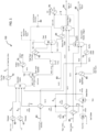
FIG. 1 , shown therein and designated by thereference numeral 100 is a first embodiment of a system (non-inventive) configured to remove from a gaseous stream using Mg(OH)2 and to regenerate the Mg(OH)2.System 100 is configured to absorb carbon dioxide from agas stream 2 and regenerate at least one of the reactants, e.g., magnesium hydroxide, used in the absorption process.System 100 comprises anabsorption reactor 10 configured to absorb CO2 from a gaseous stream; a solid-liquid separator 20 configured to separate carbonate solids from aqueous magnesium chloride; adryer 30 configured to remove a portion of water from the aqueous magnesium chloride forming magnesium chloride solids; afirst decomposition reactor 40 configured to convert the magnesium chloride to magnesium hydroxychloride, and asecond decomposition reactor 45 configured to convert the magnesium hydroxychloride to magnesium hydroxide. Also illustrated insystem 100 is a plurality of heaters and heating fluid systems to elevate the temperatures of the different reactants. - Prior to treating the carbon dioxide containing
gas stream 2, the temperature ofgas stream 2 may be lowered. In the instance of a hot gas stream, (e.g., gas turbine exhaust),gas stream 2 can provide process heat that is transferred to different units in the system. The process heat can be transferred to one or more of boilers, pre-heaters, reactors, ordryers 30 in the system. For example, in the embodiment shown, process heat can be transferred to a recycling heating fluid such as a hot oil system configured to provide indirect heating to the decomposition reactor. Process heat can also be used to heat a boiler configured to generate superheated steam for direct steam injection into the decomposition reactor. A second recycling heating fluid, such as a second hot oil system, can be configured to provide indirect heating todryer 30 to remove water from the MgCl2 containing starting material. - After heat has been removed from
gas stream 2,gas stream 2 entersabsorption reactor 10 configured to react the CO2 with CaCl2 and Mg(OH)2 via the following overall reactions:
CaCl2 + Mg(OH)2 + CO2 → CaCO3 + MgCl2+ H2O (1)
-
Reactor 10 can be configured to receive CaCl2 feed 3,gas stream 2, and a Mg(OH)2 feed.Absorption reactor 10 can be configured to operate at temperatures greater than 165 °C, such as between about 170 to 250 °C. The operation temperature ofreactor 10 can be at least 170, 175, 180, 185, 190, 195, 200, 210, 220, 230, or 240°C. The operation temperature ofreactor 10 can be between 175 and 185 °C. To maintain a temperature above the operation temperature,reactor 10 can be configured similar to a distillation column, with a water reflux entering the top of the column and a heat input at the bottom of the column to maintain a bottom liquid product at the operation temperature, such as about 175 °C. - The reactants can be preheated to the operation temperature prior to introducing into
absorption reactor 10. For example, acalcium chloride feed 3 is preheated inheater 60 prior to being added toabsorption reactor 10. Awater feed 4 may also be preheated inheater 61. As the reaction of CO2 with hydroxide is exothermic, heat can be removed fromreactor 10 to maintain operation temperature. A circulating heating fluid loop (not shown) can be configured to transfer heat fromreactor 10 to CaCl2 feed 5, such as throughheater 60. Similarly, a separate circulating heating fluid loop (not shown) can be configured to transfer heat fromreactor 10 towater feed 4, such as throughheater 61. By way of example, approximately 18.46 MW (63 MMBtu/hr) of process heat (such as from reactor 10) can be needed to heat 0.76 kmol/hr (1,679 lb*mol/hr) of CaCl2 ∗2H2O solids from 25°C to 175°C and melt the solids at its melting point of 175°C, and to heat 0.76 kmol/hr (1,679 lb*mol/hr) of water from 25°C to 100°C, vaporize the water, and superheat the steam to 175°C. - Calcium chloride can be added to
reactor 10 in one of three forms to absorption reactor 10: anhydrous CaCl2, CaCl2 ∗2H2O, or CaCl2 ∗4H2O. A molar ratio of water to CaCl2 of about 3:1 or less can be added to the absorption column for every mole of CO2 that is captured. CaCl2 ∗2H2O and water can be fed toabsorption reactor 10 to create an equivalent mixture of CaCl2 ∗3H2O (67.2 wt% aqueous CaCl2). CaCl2 feed 3 in dihydrate form can be converted from a solid phase to a liquid phase prior to enteringreactor 10. -
Reactor 10 is configured to comprise an outlet for aqueous slurry of CaCO3 solids in aqueous MgCl2 and an outlet forgas stream 2 that contains a reduced amount of CO2 than that inputted intoreactor 10.Gas stream 2 with the reduced CO2 concentration can exitsabsorption reactor 10 and can then pass through gas cooler 72 where heat can be further recovered beforegas stream 2 is exhausted to the atmosphere or further processed downstream. The heat can be used to pre-heat the reactants, such as CaCl2 and optionally water. As a result of the absorption column, the amount of CO2 ingas stream 2 can be reduced by at least 30%, 40%, 50%, 60%, 70%, 80%, 90%, 95%, 98%, or 99%. - At least 50 wt% aqueous MgCl2 can exit the
absorption reactor 10 and enter solid-liquid separator 20, which separates the CaCO3 solids from the aqueous solution. A weight percent of aqueous MgCl2 between 50 to 60% can exitabsorption reactor 10 and enter solid-liquid separator 20, such as 51%, 53%, 55%, 57%, or 59% wt MgCl2. A major portion of MgCl2 in the aqueous solution can be in the form of MgCl2 tetrahydrate. - Water may be added to solid-
liquid separator 20 to facilitate the separation of the carbonate solids. The amount of water to be added can dilute the solution by less than 30%, 25%, 20%, 15%, 10%, or 5%. Once separated, the hot CaCO3 solids can be passed through a cooler 70 for energy recovery before being sent to storage. - After separating the carbonate solids from the aqueous MgCl2, the aqueous solution is transferred to
dryer 30 to remove water from the solution. A sufficient amount of water can be evaporated from the solution so that the ratio of water to MgCl2 is less than about 2.5:1, or less than about 2 to 1. A major portion of the water in the magnesium chloride-containingmaterial exiting dryer 30 can be in the form of MgCl2 dihydrate. For example, the magnesium chloride containing material comprises at least 55%, 60%, 65% 70%, 75% 80%, 85% 90%, 95%, or 98% of MgCl2 ∗2H2O (s). The primary reaction indryer 30 is provided below:
MgCl2 ∗4H2O (l) → MgCl2 ∗2H2O (s) + 2 H2O (g) (2)
- To supply the needed energy to remove a portion of the water, heat can be supplied to the vessel to keep the operation temperature at between 150 to 250°C, such as 160, 170, 180, 190, 200, 210, 220, 230, or 240°C. The temperature can be kept between 195 and 205°C or 198 and 202°
C. Dryer 30 is configured such that superheated steam (and potentially some HCl) exits the top of the vessel, while magnesium chloride containing material comprising dihydrate salts moves tofirst decomposition reactor 40. Operation pressures can be at atmospheric pressure. The superheated steam produced fromdryer 30 can supply at least a portion of the steam required fordecomposition reactors 40 and/or 45. - The aqueous MgCl2 solution can be pumped through a
heater 62 before enteringdryer 30 to raise the temperature of the solution to substantially equal to the operation temperatures ofdryer 30. Heat can be transferred to the solution atheater 62 by a circulatingheating fluid loop 83 configured to transfer heat fromgas stream 2 to the aqueous solution. -
System 100 can comprise anevaporator 30 that is configured to reduce the water content so that MgCl2 turns to solid and the solid material can be transferred tofirst decomposition reactor 40. For example,evaporator 30 can comprise a flash drum having a scraper or other agitator configured to facilitate conveyance to solid material. Inevaporator 30, a pressurized MgCl2 solution at the operation temperature can be flashed to atmospheric pressure to remove water from the aqueous solution and produce MgCl2 ∗2H2O solids. A portion of the heating fluid in circulatingloop 83 may be directed toevaporator 30 to maintain the operation temperatures ofevaporator 30. -
System 100 can comprise adryer 30 that is configured to reduce the water content so that aqueous MgCl2 turns to solid and the solid material can be transferred tofirst decomposition reactor 40.Dryer 30 can be configured to apply indirect contact heating or direct contact heating using a medium such as air to maintain operation temperatures. For example,dryer 30 can be a rotary dryer, a flash dryer, or a spray dryer. In some embodiments, a portion of the heating fluid in circulatingloop 83 may be directed todryer 30 to maintain the operation temperatures ofdryer 30 and may also be directed to blower to heat the drying medium such as air. In lieu ofdryer 30,system 100 can comprise a flaker, a crystallizer, or a priller configured to reduce the water content so that the molar ratio is about 2:1 and/or the MgCl2 is mostly in a dihydrate form and can be transferred tofirst decomposition reactor 40. - By way of example, the heat input needed to raise the temperature of the aqueous solution to an operation temperature of 200°C is approximately 2.05 MW (7 MMBtu/hr). Further, also by way of example, the heat input needed to reduce the water content of an aqueous solution where the molar ratio of water is 4:1 is approximately 20.81 MW (71 MMBtu/hr). For circulating
heating fluid loop 83, the fluid return temperature can be about 5 to 15°C above the operation temperature, e.g., 210°C, for thefluid leaving dryer 30 orheater 62. In addition, the fluid supply temperature (e.g., the temperature of thefluid approaching dryer 30 or heater 62) can be about 20 to 30°C above the operation temperature or 10 to 20°C above the return temperature, e.g., 225°C. At the intercept ofloop 83 withgas stream 2, the temperature ofgas stream 2 can be a temperature that is at least 30 to 40 above the operation temperature ofdecomposition reactor 40. The temperature ofgas stream 2 after transferring heat toloop 83 can be at least 235 °C. -
System 100 comprises reactors configured for a two stage, counter-current flow decomposition reactor to convert MgCl2 to Mg(OH)2. Within the first stage,reactor 40 is configured for the following reaction to occur:
MgCl2 ∗2H2O (s) → Mg(OH)Cl (s) + HCl (g) + H2O (g) (3)
Within the second stage,reactor 45 is configured for the following reaction to occur:
Mg(OH)Cl (s) + H2O (g) → Mg(OH)2 (s) + HCl (g) (4)
- In
second reactor 45, steam can be counter-currently contacted with MgOHCl solids fed fromfirst reactor 40. Steam can be generated by aboiler 90 that is heated bygas stream 2. Also, steam recycled from the exhaust ofreactors boiler 90 to feedreactor 45. Recycled steam may be heated by aheater 65 to obtain the desired final steam temperature to feedreactor 45. Steam is introduced intoreactor 45 at a temperature that is substantially the same as the operation temperature ofreactor 45 as described below. For example, steam can be introduced intoreactor 45 at a temperature between 385°C and 395°C, such as about 390°C. - The Mg(OH)2
solids exiting reactor 45 are in equilibrium with thevapor leaving reactor 45. The exitingvapor leaving reactor 45 can comprise at least 0.8 mole of HCl for every mole of Mg(OH)2 produced. For example, the exitingvapor leaving reactor 45 can comprise 0.85 mole of HCl, 0.9 mole of HCl, 0.95 mole of HCl, 0.98 mole HCl for ever mole of Mg(OH)2 produced. The rate of counter-flow throughreactor 45 is sufficient to keep the partial pressure of HCl low enough so that reaction (5) equilibrium is shifted to the right. The counter flow can be 100% superheated steam. The counter flow can also comprise superheated steam and an inert carrier gas. The partial pressure of HCl can be maintained at a sufficiently low amount by operating thedecomposition reaction 45 under vacuum conditions. - In
reactor 40, the vapor mixture of superheated steam andHCl leaving reactor 45 is counter-currently contacted with the magnesium chloride material fed from dryer orevaporator 30 comprising MgCl2 ∗2H2O solids. In some embodiments, only a portion of thesteam exiting reactor 45 is fed toreactor 40. For example, a majority of thevapor exiting reactor 45 can bypassreactor 40 so that additional heat can be recovered in theHCl condenser 76. The Mg(OH)Clsolids exiting reactor 40 can be in equilibrium with thevapor leaving reactor 40. The exitingvapor leaving reactor 40 can comprise at least an additional 0.8 mole of HCl for every mole ofMgOHCl produced. For example, the exitingvapor leaving reactor 40 can comprise an additional 0.85 mole of HCl, 0.9 mole of HCl, 0.95 mole of HCl, 0.98 mole HCl for every mole of MgOHCl produced. The rate of counter-flow throughreactor 40 is sufficient to keep the partial pressure of HCl low enough to maintain a shift of reaction (4) to the right. - The operation temperature for
reactor 45 can be between 380°C and 500°C, such as about 390, 400, 410, 420, 430, 440, 450, 460, 470, or 490°C. The operation temperature forreactor 45 can be between about 385°C and 395°C, such as about 390°C. The operation temperature forreactor 40 can be between 250°C and 400°C, such as 260, 270, 280, 290, 300, 310, 320, 330, 340, 350, 360, 370, 380, or 390°C. The operation temperature ofreactor 40 can be between about 275°C and 285°C, such as about 280°C. By way of example, the steam requirements for the two-stage counter-current configuration can be approximately 3.9 kg/hr (8.6 lb/hr) of steam per 0.45 kg/hr (1 lb/hr) HCl at 390°C forsecond reactor 45 and 280°C forfirst reactor 40. - An output of
reactor 40 comprises solid MgOHCl. The solid phase output ofreactor 40 can be at least 55%, 60%, 65% 70%, 75% 80%, 85% 90%, 95%, 98%, or 99% of MgOHCl. An output ofreactor 45 comprises solid Mg(OH)2. The solid phase output ofreactor 45 can be at least 55%, 60%, 65% 70%, 75% 80%, 85% 90%, 95%, 98%, or 99% of Mg(OH)2. - To maintain operation temperatures of
reactors decomposition reactors reactor heating fluid loop 84 is configured to transfer heat fromgas stream 2 toreactor 40 and circulatingheating fluid loop 85 is configured to transfer heat fromgas stream 2 toreactor 45. - The MgCl2 containing
material exiting dryer 30 can be conveyed through aheater 64 before enteringreactor 40 to raise the temperature of the solution to substantially equal to the operation temperatures ofreactor 40. While not shown in the one illustrated, a portion of the heating fluid in circulatingloop 84 may be directed toheater 64 to heat the MgCl2 containing material fed toreactor 40. - For circulating
heating fluid loop 85, the fluid return temperature (e.g., for the heatingfluid leaving reactor 45 and heater 65) can be about 5 to 15°C above the operation temperature ofreactor 40; e.g., the fluid return temperature can be about 400°C. In addition, the fluid supply temperature (e.g., the temperature of thefluid approaching reactor 45 and heater 65) can be about 10 to 45°C above the operation temperature or 5 to 25°C above the return temperature; e.g., the fluid supply temperature can be about 415°C. At the intercept ofloop 85 withgas stream 2, the temperature ofgas stream 2 can be greater than 500°C or greater than 600°C, e.g., the temperature of a flue gas exhaust stream. The temperature ofgas stream 2 after transferring heat toloop 85 can be at least 10°C higher than the temperature of the heatingfluid approaching reactor 45. - For circulating
heating fluid loop 84, the fluid return temperature (e.g., the temperature of the heatingfluid leaving reactor 40 or heater 64) can be about 5 to 15°C above the operation temperature ofreactor 45; e.g., the fluid return temperature can be about 290°C. In addition, the fluid supply temperature (e.g., the temperature of thefluid approaching reactor 40 or heater 64) can be about 5 to 20°C above the operation temperature or 60 to 100°C above the return temperature; e.g., the fluid supply temperature can be about 355°C. At the intercept ofloop 84 withgas stream 2, the temperature ofgas stream 2 can be greater than 500°C or greater than 600°C, e.g., the temperature of a flue gas exhaust stream. In some embodiments, the temperature ofgas stream 2 after transferring heat toloop 85 can be at least 10 degrees higher than the temperature of the heatingfluid approaching reactor 40. - The hot Mg(OH)2
solids exiting reactor 45 can be passed through a solids product cooler 74 before enteringabsorption reactor 10, while the vaporproduct exiting reactor 40 is combined with thevapor bypass 6 aroundreactor 40. The combined vapor stream passes throughHCl condenser 76 before being pumped to an HCl product tank. - As evident from the operation temperatures of the decomposition reactor, there are significant enthalpy requirements for the decomposition reactor, namely, the reaction enthalpy for the decomposition of MgCl2 ∗2H2O to Mg(OH)2 and HCl and the superheated steam requirements for direct steam injection into the decomposition reactor.
System 100 can comprise a gas turbine or be configured to receivegas stream 2 produced from a gas turbine, such as a60MW gas turbine 95 in the embodiment shown. The overall CO2 capture rate can be greater than 70%, 80%, 90%, 95%, or greater than 99%. - In addition to a first gas turbine,
system 100 can comprise a furnace (not shown) to burn supplemental natural gas, and use heat recovered from the flue gas at the flame temperature to provide additional heat for steam generation withinsystem 100. For a two-stage counter-current reactor, the total enthalpy requirement for the process can be about 51.29 MW (175 MMBtu/hr). The heat available from 60 MW turbine exhaust gas is about 42.79 MW (146 MMBtu/hr), leaving an overall deficiency of about 8.5 MW (29 MMBtu/hr) that would be required to achieve 100% CO2 capture. Burning 1,562 Nm3/hr @ 0°C (1.4 MMSCFD) of supplemental natural gas in a furnace can provide heat recovery from the flue gas of 13.16 MW (44.9 MMBtu/hr). An additional 4.69 to 4.98 MW (16-17 MMBtu/hr) of enthalpy would be required withinsystem 100 to capture this additional CO2. This results in a net enthalpy surplus that could be used to achieve 100% CO2 capture. If this 1,562 Nm3/hr @ 0°C (1.4 MMSCFD) of natural gas were instead fired in a turbine, 5.6 MW of additional electricity could be produced (relative to the 60 MW of electricity produced in the existing turbine). - Referring now to
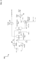
FIG. 2 , shown therein and designated by thereference numeral 200 is a second embodiment of a system (non-inventive) configured to remove from a gaseous stream using Mg(OH)2 and regenerate the Mg(OH)2.Embodiment 200 is substantially similar toembodiment 100 described above, except that the decomposition process comprises only a single stage counter flowreactor 48 and circulatingheating fluid loop 86 instead ofloops reactor 48 can be between 340°C -360°C, such as 350 °C. The superheated steam can be introduced at a temperature substantially the same as the operation temperature. - Referring now to
FIG. 3 , shown therein and designated byreference numeral 300 is an embodiment of a two-stage CO2 absorption process that can be substituted for the one stage absorption process described above in connection withreactor 10. The two-stage process is substantially similar to the conditions described for the one-stage process except that two reactors are used instead of one and a slightly higher molar ratio of water to MgCl2 is required. Within the first stage,reactor 12 is configured for the following reaction to occur:
Mg(OH)2 (s) + CO2 (g) → MgCO3 (aq) + H2O (l) (5)
Within the second stage,reactor 14 is configured for the following reaction to occur:
CaCl2 (aq) + MgCO3 (aq) → CaCO3 (s) + MgCl2 (aq) (6)
- In
reactor 12, the molar ratio of water to MgCO3 can be about 3.5:1 or about 3:1. Inreactor 14, the molar ratio of water to MgCl2 can be about 5.5:1 or about 5:1. - The above specification and examples provide a complete description of the structure and use of exemplary embodiments. Although certain embodiments have been described above with a certain degree of particularity, or with reference to one or more individual embodiments, those skilled in the art could make numerous alterations to the disclosed embodiments without departing from the scope of this invention. As such, the illustrative embodiments of the present systems (non-inventive) and processes (inventive) for removing carbon dioxide from a gaseous stream and regenerating magnesium hydroxide are not intended to be limiting. Rather, the present methods include all modifications and alternatives falling within the scope of the claims, and embodiments other than those shown may include some or all of the features of the depicted embodiments.
Claims (3)
- A method of regenerating Mg(OH)2 in a process that reduces the amount of CO2 contained in a gas stream, comprising:(a) reacting MgCl2 containing material with steam in a first admixture, preferably at a temperature from about 250°C to about 350°C, to form step (a) products comprising Mg(OH)Cl, preferably in an amount of greater than 90% by weight, and HCl, where the MgCl2 containing material comprises a water to MgCl2 ratio of less than about 2.5:1;(b) reacting Mg(OH)Cl with steam in a second admixture, preferably at a temperature from about 350°C to about 500°C, to form step (b) products comprising HCl and magnesium-containing products comprising mostly Mg(OH)2;(c) reacting Mg(OH)2 with CO2, CaCl2, and steam, preferably at a temperature from about 140°C to about 220°C, to form step (c) products comprising MgCl2 and CaCO3, said step preferably comprising admixing Mg(OH)2 from step (b) with CO2 contained in the gas stream in a third admixture to form first step (c) products comprising MgCO3 and H2O, and admixing the MgCO3 from first step (c) products with CaCl2 in a fourth admixture, preferably with a ratio of water to MgCl2 of about 4 to 1, to form a second step (c) products comprising CaCO3 and MgCl2.
- The method of claim 1, comprising passing a gaseous outflow comprising HCl and steam from step (b) to the reaction of step (a).
- The method of claim 1, further comprising in case of a ratio of water to MgCl2 in the fourth admixture of about 4 to 1 separating at least a portion of the CaCO3 from the second step (c) products and removing a portion of the water from the remaining second step (c) products so the ratio of water to MgCl2 is about 2 to 1.
Priority Applications (1)
| Application Number | Priority Date | Filing Date | Title |
|---|---|---|---|
| EP23182535.7A EP4230583A3 (en) | 2015-02-23 | 2016-02-23 | Carbon dioxide sequestration with magnesium hydroxide and regeneration of magnesium hydroxide |
Applications Claiming Priority (2)
| Application Number | Priority Date | Filing Date | Title |
|---|---|---|---|
| US201562119633P | 2015-02-23 | 2015-02-23 | |
| PCT/US2016/019164 WO2016138016A1 (en) | 2015-02-23 | 2016-02-23 | Carbon dioxide sequestration with magnesium hydroxide and regeneration of magnesium hydroxide |
Related Child Applications (2)
| Application Number | Title | Priority Date | Filing Date |
|---|---|---|---|
| EP23182535.7A Division EP4230583A3 (en) | 2015-02-23 | 2016-02-23 | Carbon dioxide sequestration with magnesium hydroxide and regeneration of magnesium hydroxide |
| EP23182535.7A Division-Into EP4230583A3 (en) | 2015-02-23 | 2016-02-23 | Carbon dioxide sequestration with magnesium hydroxide and regeneration of magnesium hydroxide |
Publications (5)
| Publication Number | Publication Date |
|---|---|
| EP3261991A1 EP3261991A1 (en) | 2018-01-03 |
| EP3261991A4 EP3261991A4 (en) | 2018-12-12 |
| EP3261991B1 EP3261991B1 (en) | 2023-08-02 |
| EP3261991C0 EP3261991C0 (en) | 2023-08-02 |
| EP3261991B9 true EP3261991B9 (en) | 2023-11-15 |
Family
ID=56789488
Family Applications (2)
| Application Number | Title | Priority Date | Filing Date |
|---|---|---|---|
| EP16756203.2A Active EP3261991B9 (en) | 2015-02-23 | 2016-02-23 | Carbon dioxide sequestration with magnesium hydroxide and regeneration of magnesium hydroxide |
| EP23182535.7A Pending EP4230583A3 (en) | 2015-02-23 | 2016-02-23 | Carbon dioxide sequestration with magnesium hydroxide and regeneration of magnesium hydroxide |
Family Applications After (1)
| Application Number | Title | Priority Date | Filing Date |
|---|---|---|---|
| EP23182535.7A Pending EP4230583A3 (en) | 2015-02-23 | 2016-02-23 | Carbon dioxide sequestration with magnesium hydroxide and regeneration of magnesium hydroxide |
Country Status (18)
| Country | Link |
|---|---|
| US (4) | US10583394B2 (en) |
| EP (2) | EP3261991B9 (en) |
| JP (1) | JP6808633B2 (en) |
| KR (3) | KR20240027848A (en) |
| CN (2) | CN107531500A (en) |
| AU (1) | AU2016222869B2 (en) |
| BR (1) | BR112017017948B1 (en) |
| CA (1) | CA2977650C (en) |
| EA (1) | EA037086B1 (en) |
| ES (1) | ES2961349T3 (en) |
| HU (1) | HUE063651T2 (en) |
| IL (1) | IL254091B (en) |
| MX (1) | MX2017010838A (en) |
| PH (1) | PH12017501526A1 (en) |
| PL (1) | PL3261991T3 (en) |
| SG (1) | SG11201706866UA (en) |
| WO (1) | WO2016138016A1 (en) |
| ZA (1) | ZA201706354B (en) |
Families Citing this family (8)
| Publication number | Priority date | Publication date | Assignee | Title |
|---|---|---|---|---|
| KR102140915B1 (en) * | 2018-11-27 | 2020-08-05 | 한국에너지기술연구원 | Carbon dioxide mineralization reactor and carbon dioxide immobilization method |
| WO2021030529A1 (en) | 2019-08-13 | 2021-02-18 | California Institute Of Technology | Process to make calcium oxide or ordinary portland cement from calcium bearing rocks and minerals |
| JP7291043B2 (en) | 2019-09-13 | 2023-06-14 | シャープ株式会社 | Air cleaner |
| CN112007946B (en) * | 2020-07-28 | 2021-06-18 | 南京大学环境规划设计研究院股份公司 | Ectopic bioremediation device for pollutants |
| US11858819B2 (en) | 2021-03-04 | 2024-01-02 | Energy And Environmental Research Center Foundation | Methods of producing a syngas composition |
| US11717802B2 (en) | 2021-03-04 | 2023-08-08 | Energy And Environmental Research Center Foundation | Methods of treating metal carbonate salts |
| WO2023053067A1 (en) * | 2021-10-01 | 2023-04-06 | Negative Emissions Materials, Inc. | Attritive carbon dioxide capture as friable magnesium carbonate particulates |
| WO2024044690A1 (en) * | 2022-08-24 | 2024-02-29 | Carbonfree Chemicals Holdings, Llc | Passive and forced synthesis of mg(oh)2 for the purpose of supplying magnesium-based capture of co2 |
Family Cites Families (119)
| Publication number | Priority date | Publication date | Assignee | Title |
|---|---|---|---|---|
| US2013334A (en) * | 1934-10-17 | 1935-09-03 | Dow Chemical Co | Method of producing magnesium chloride from calcium chloride |
| US2383674A (en) | 1941-08-21 | 1945-08-28 | Hooker Electrochemical Co | Process for production of sodium bicarbonate |
| US2357130A (en) | 1942-05-05 | 1944-08-29 | Harbison Walker Refractories | Production of magnesium chloride from calcium chloride and dolomite |
| US2962350A (en) | 1957-12-03 | 1960-11-29 | Aluminium Lab Ltd | Production of precipitated calcium carbonate |
| GB991612A (en) | 1961-04-17 | 1965-05-12 | Ciba Ltd | Epoxide resin compositions |
| US3801698A (en) | 1971-01-18 | 1974-04-02 | Stone & Webster Eng Corp | Removal of acidic gases from hydrocarbon streams |
| JPS4923797A (en) | 1972-06-28 | 1974-03-02 | ||
| US4147599A (en) | 1977-07-19 | 1979-04-03 | Diamond Shamrock Corporation | Production of alkali metal carbonates in a cell having a carboxyl membrane |
| US3855398A (en) | 1973-04-12 | 1974-12-17 | Allied Chem | Sodium carbonate and bicarbonate sperulites from chlorine electrolytic cell liquors |
| AR208406A1 (en) | 1974-05-22 | 1976-12-27 | Rhone Poulenc Ind | PROCEDURE AND APPARATUS TO OBTAIN SODIUM BICARBONATE |
| JPS5285997A (en) | 1976-01-09 | 1977-07-16 | Sumitomo Chem Co Ltd | Purification of alkali |
| US4069117A (en) | 1976-01-28 | 1978-01-17 | Cooper Hal B H | Process for removing and recovering acidic gases from gaseous mixtures containing them |
| US4128701A (en) | 1977-12-23 | 1978-12-05 | United Technologies Corp. | Hydrogen/chlorine regenerative fuel cell |
| CA1118579A (en) | 1978-10-18 | 1982-02-23 | Societe Nationale De L'amiante | Filtering of precipitating silica |
| JPS6148587A (en) | 1984-08-14 | 1986-03-10 | Asahi Glass Co Ltd | Method for adding hydrochloric acid to electrolytic cell |
| GB8423642D0 (en) | 1984-09-19 | 1984-10-24 | Ici Plc | Electrolysis of alkali metal chloride solution |
| ATE50548T1 (en) | 1984-11-27 | 1990-03-15 | Sulzer Ag | PROCESS FOR PRODUCTION OF HIGH PURITY MAGNESIUM OXIDE. |
| US4749453A (en) | 1986-01-10 | 1988-06-07 | The Boeing Company | Method and apparatus for making hydrochloric acid and sodium hydroxide |
| US4764286A (en) | 1986-06-26 | 1988-08-16 | The Dow Chemical Company | Catalytic decomposition of sodium hypochlorite in highly alkaline solutions |
| US5080799A (en) | 1990-05-23 | 1992-01-14 | Mobil Oil Corporation | Hg removal from wastewater by regenerative adsorption |
| RU2019271C1 (en) | 1992-04-28 | 1994-09-15 | Всероссийский научно-исследовательский институт углеводородного сырья | Method for purification of pyrogas against carbon dioxide and hydrogen sulfide |
| RU2031695C1 (en) | 1992-04-28 | 1995-03-27 | Всероссийский научно-исследовательский институт углеводородного сырья | Method for purifying pyrogas against carbon and hydrogen sulfide |
| RU2054959C1 (en) | 1992-06-24 | 1996-02-27 | Научно-производственное объединение "Эмекат" | Carbon oxide and hydrocarbons discharging gasses purification method and method to prepare catalyst for its realization |
| JP3329662B2 (en) | 1996-06-18 | 2002-09-30 | 住友大阪セメント株式会社 | Method for producing silica gel and silica sol |
| DE19631794A1 (en) | 1996-08-07 | 1997-08-07 | Peter Prof Pohl | Removal of carbon di:oxide from exhaust gas of incinerators |
| US6908570B2 (en) | 1996-08-14 | 2005-06-21 | Discovery Resources, Inc. | Compositions for improved recovery of metals |
| US5888256A (en) | 1996-09-11 | 1999-03-30 | Morrison; Garrett L. | Managed composition of waste-derived fuel |
| AU5593298A (en) | 1996-12-05 | 1998-06-29 | Dow Chemical Company, The | Process for preparing calcium carbonate which contains low concentrations of non-calcium metals |
| JP3402101B2 (en) * | 1996-12-25 | 2003-04-28 | 栗田工業株式会社 | Organochlorine photolysis equipment |
| WO2000010691A1 (en) | 1998-08-18 | 2000-03-02 | United States Department Of Energy | Method and apparatus for extracting and sequestering carbon dioxide |
| US6592829B2 (en) | 1999-06-10 | 2003-07-15 | Praxair Technology, Inc. | Carbon dioxide recovery plant |
| US6340736B1 (en) | 1999-11-29 | 2002-01-22 | General Electric Company | Method and apparatus for the production of polycarbonates with brine recycling |
| US6488740B1 (en) | 2000-03-01 | 2002-12-03 | Electric Power Research Institute, Inc. | Apparatus and method for decreasing contaminants present in a flue gas stream |
| DE20012514U1 (en) | 2000-07-17 | 2001-01-04 | Meissner Uwe | Dog leash |
| KR100400179B1 (en) | 2001-03-15 | 2003-10-01 | 김명한 | Method of decoloration of blue jean adaptable to client's design |
| JP2002273163A (en) | 2001-03-19 | 2002-09-24 | Susumu Otsuki | Method for removing carbon dioxide included in combustion exhaust gas |
| EP1382567B1 (en) | 2001-03-28 | 2014-09-24 | Osaka Gas Co., Ltd. | Carbon monoxide removal method |
| RU2199374C1 (en) | 2001-06-13 | 2003-02-27 | Казанское открытое акционерное общество "Органический синтез" | Method of alkali purification of pyrolysis gases |
| CA2352626A1 (en) | 2001-07-12 | 2003-01-12 | Co2 Solution Inc. | Coupling for linking a hydrogen fuel cell to an enzyme bioreactor for processing and sequestering co2 |
| US6676824B2 (en) | 2001-07-18 | 2004-01-13 | Hatch Associates Ltd. | Process for purification of molten salt electrolytes |
| US7527770B2 (en) | 2001-08-01 | 2009-05-05 | Battelle Memorial Institute | Photolytic oxygenator with carbon dioxide fixation and separation |
| US7427449B2 (en) | 2001-10-23 | 2008-09-23 | General Dynamics Information Technology, Inc. | Integrated oxygen generation and carbon dioxide absorption method apparatus and systems |
| AU2003256837A1 (en) | 2002-07-26 | 2004-02-16 | Muna Ahmed Abu-Dalo | Removing metals from solution using metal binding compounds and sorbents therefor |
| US7922992B2 (en) | 2002-09-13 | 2011-04-12 | Ica Trinova, Llc | Composition and method for producing carbon dioxide |
| US20040126293A1 (en) | 2002-10-23 | 2004-07-01 | Geerlings Jacobus Johannes Cornelis | Process for removal of carbon dioxide from flue gases |
| DE10255239A1 (en) | 2002-11-26 | 2004-06-09 | Basf Ag | Process for the removal of mercury from solutions contaminated with mercury |
| JP2004174369A (en) | 2002-11-27 | 2004-06-24 | Meidensha Corp | Gas treatment method and system therefor |
| WO2004094023A2 (en) | 2003-04-21 | 2004-11-04 | Manufacturing And Technology Conversion, Inc. | Process for the treatment of waste or gaseous streams |
| US20040213705A1 (en) | 2003-04-23 | 2004-10-28 | Blencoe James G. | Carbonation of metal silicates for long-term CO2 sequestration |
| US7132090B2 (en) | 2003-05-02 | 2006-11-07 | General Motors Corporation | Sequestration of carbon dioxide |
| US7604787B2 (en) | 2003-05-02 | 2009-10-20 | The Penn State Research Foundation | Process for sequestering carbon dioxide and sulfur dioxide |
| US20050011770A1 (en) | 2003-07-18 | 2005-01-20 | Tatenuma Katsuyoshi | Reduction method of atmospheric carbon dioxide, recovery and removal method of carbonate contained in seawater, and disposal method of the recovered carbonate |
| FR2863911B1 (en) | 2003-12-23 | 2006-04-07 | Inst Francais Du Petrole | CARBON SEQUESTRATION PROCESS IN THE FORM OF A MINERAL IN WHICH THE CARBON IS AT THE DEGREE OF OXIDATION +3 |
| US7722842B2 (en) | 2003-12-31 | 2010-05-25 | The Ohio State University | Carbon dioxide sequestration using alkaline earth metal-bearing minerals |
| WO2006009600A2 (en) | 2004-05-04 | 2006-01-26 | The Trustees Of Columbia University In The City Of New York | Systems and methods for extraction of carbon dioxide from air |
| US7699909B2 (en) | 2004-05-04 | 2010-04-20 | The Trustees Of Columbia University In The City Of New York | Systems and methods for extraction of carbon dioxide from air |
| WO2005108297A2 (en) | 2004-05-04 | 2005-11-17 | The Trustees Of Columbia University In The City Of New York | Carbon dioxide capture and mitigation of carbon dioxide emissions |
| NO20042646D0 (en) | 2004-05-12 | 2004-06-23 | Promeks As | Improved process for the production of pure amorphous silica especially zerogel for stabilization of ol, as well as for insulation formula |
| CA2577685A1 (en) | 2004-08-20 | 2006-04-06 | Global Research Technologies, Llc | Removal of carbon dioxide from air |
| WO2006023743A2 (en) | 2004-08-20 | 2006-03-02 | The Trustees Of Columbia University In The City Of New York | Laminar scrubber apparatus for capturing carbon dioxide from air and methods of use |
| US20060051274A1 (en) | 2004-08-23 | 2006-03-09 | Wright Allen B | Removal of carbon dioxide from air |
| US7727374B2 (en) | 2004-09-23 | 2010-06-01 | Skyonic Corporation | Removing carbon dioxide from waste streams through co-generation of carbonate and/or bicarbonate minerals |
| JP2006137620A (en) | 2004-11-10 | 2006-06-01 | Toshiba Corp | Collection system for carbon dioxide in waste gas, and its collection method |
| CA2595916A1 (en) | 2005-02-02 | 2006-08-10 | Global Research Technologies, Llc | Removal of carbon dioxide from air |
| US8864876B2 (en) | 2005-02-14 | 2014-10-21 | Neumann Systems Group, Inc. | Indirect and direct method of sequestering contaminates |
| US7866638B2 (en) | 2005-02-14 | 2011-01-11 | Neumann Systems Group, Inc. | Gas liquid contactor and effluent cleaning system and method |
| FR2882998B1 (en) | 2005-03-08 | 2007-06-08 | Solvay | PROCESS FOR OBTAINING SODIUM CARBONATE CRYSTALS |
| US7909911B2 (en) | 2007-10-18 | 2011-03-22 | The Trustees Of Columbia University In The City Of New York | Carbon dioxide permeable membrane |
| US20130213280A9 (en) | 2005-04-18 | 2013-08-22 | Klaus S. Lackner | Methods and systems for reducing carbon dioxide emissions |
| WO2006113673A2 (en) | 2005-04-18 | 2006-10-26 | The Trustees Of Columbia University In The City Of New York | Methods and systems for reducing emissions |
| US7371357B2 (en) | 2005-04-27 | 2008-05-13 | Clean World Strategies Corp. | Process for removal of pollutants |
| CA2613096C (en) * | 2005-07-05 | 2012-08-21 | Greensols Australia Pty Ltd. | Preparation and use of cationic halides, sequestration of carbon dioxide |
| US20070187247A1 (en) | 2005-07-20 | 2007-08-16 | Lackner Klaus S | Electrochemical methods and processes for carbon dioxide recovery from alkaline solvents for carbon dioxide capture from air |
| EP2409753B1 (en) | 2005-07-28 | 2017-07-19 | Carbon Sink Inc. | Removal of carbon dioxide from air |
| ATE481356T1 (en) | 2005-12-20 | 2010-10-15 | Shell Int Research | METHOD FOR SEQUESTRING CARBON DIOXIDE |
| WO2007078017A1 (en) | 2005-12-31 | 2007-07-12 | Korea Institute Of Geoscience And Mineral Resources | Novel manufacturing method of aragonite calcium carbonate |
| RU2008139902A (en) | 2006-03-08 | 2010-04-20 | ГЛОБАЛ РИСЕРЧ ТЕКНОЛОДЖИЗ, ЭлЭлСи (US) | AIR INTAKE DEVICE WITH FUNCTIONALIZED ION EXCHANGE MEMBRANE FOR CO2 COLLECTION FROM THE EXTERNAL ENVIRONMENT |
| ES2440946T3 (en) | 2006-03-10 | 2014-01-31 | C-Quest Technologies International Llc | Carbon dioxide sequestration procedure |
| JP2009535198A (en) | 2006-04-27 | 2009-10-01 | プレジデント アンド フェロウズ オブ ハーバード カレッジ | Carbon dioxide capture and related processes |
| WO2008042919A2 (en) | 2006-10-02 | 2008-04-10 | Global Research Technologies, Llc | Method and apparatus for extracting carbon dioxide from air |
| KR20090082275A (en) | 2006-11-15 | 2009-07-29 | 글로벌 리서치 테크놀로지스, 엘엘씨 | Removal of carbon dioxide from air |
| US20090081096A1 (en) | 2007-03-28 | 2009-03-26 | Pellegrin Roy J | Method and means for capture and long-term sequestration of carbon dioxide |
| CN103227339B (en) | 2007-04-03 | 2016-03-09 | 新空能量公司 | Produce renewable hydrogen and retain electro-chemical systems, the apparatus and method of carbon dioxide |
| AU2008242845B2 (en) | 2007-04-17 | 2012-08-23 | Carbon Sink, Inc. | Capture of carbon dioxide (CO2) from air |
| WO2008148055A1 (en) | 2007-05-24 | 2008-12-04 | Calera Corporation | Hydraulic cements comprising carbonate compounds compositions |
| AU2008270034B2 (en) | 2007-06-28 | 2009-07-16 | Arelac, Inc. | Desalination methods and systems that include carbonate compound precipitation |
| US20090074656A1 (en) | 2007-09-18 | 2009-03-19 | Calvin Billings | Process for production of hydrogen from coal and other fossil fuels |
| CA2930096A1 (en) | 2007-09-20 | 2009-03-26 | Skyonic Corporation | Removing carbon dioxide from waste streams through co-generation of carbonate and/or bicarbonate minerals |
| US8012453B2 (en) | 2007-10-25 | 2011-09-06 | Surendra Saxena | Carbon sequestration and production of hydrogen and hydride |
| EP2212009A1 (en) | 2007-11-05 | 2010-08-04 | Global Research Technologies, LLC | Removal of carbon dioxide from air |
| EP2070578A1 (en) | 2007-12-14 | 2009-06-17 | Université Joseph Fourier | Process for the sequestration of CO2 by reaction with alkaline solid wastes |
| US7749476B2 (en) | 2007-12-28 | 2010-07-06 | Calera Corporation | Production of carbonate-containing compositions from material comprising metal silicates |
| US7754169B2 (en) | 2007-12-28 | 2010-07-13 | Calera Corporation | Methods and systems for utilizing waste sources of metal oxides |
| WO2009086460A1 (en) | 2007-12-28 | 2009-07-09 | Calera Corporation | Methods of sequestering co2 |
| WO2009102816A2 (en) | 2008-02-11 | 2009-08-20 | Auxsol, Inc. | Removing carbon dioxide from gaseous emissions |
| CA3047633C (en) | 2008-02-19 | 2023-08-01 | Carbon Sink Inc. | Extraction and sequestration of carbon dioxide |
| MX2010012947A (en) | 2008-05-29 | 2011-04-27 | Calera Corp | Rocks and aggregate, and methods of making and using the same. |
| WO2009149292A1 (en) | 2008-06-04 | 2009-12-10 | Global Research Technologies, Llc | Laminar flow air collector with solid sorbent materials for capturing ambient co2 |
| EP2212033A4 (en) | 2008-07-16 | 2013-04-24 | Calera Corp | Low-energy 4-cell electrochemical system with carbon dioxide gas |
| US7993500B2 (en) | 2008-07-16 | 2011-08-09 | Calera Corporation | Gas diffusion anode and CO2 cathode electrolyte system |
| US20110203174A1 (en) | 2008-08-11 | 2011-08-25 | Lackner Klaus S | Method and apparatus for extracting carbon dioxide from air |
| WO2010021994A1 (en) * | 2008-08-18 | 2010-02-25 | Furnary Kevin P | Scrubber for removing pollutants from flue gas |
| WO2010022399A1 (en) | 2008-08-22 | 2010-02-25 | Global Research Technologies, Llc | Removal of carbon dioxide from air |
| US7947240B2 (en) | 2008-10-08 | 2011-05-24 | Expansion Energy, Llc | System and method of carbon capture and sequestration |
| JP2010125354A (en) | 2008-11-25 | 2010-06-10 | Jian-Feng Lin | Method of capturing carbon dioxide |
| US7790012B2 (en) | 2008-12-23 | 2010-09-07 | Calera Corporation | Low energy electrochemical hydroxide system and method |
| US20110247336A9 (en) | 2009-03-10 | 2011-10-13 | Kasra Farsad | Systems and Methods for Processing CO2 |
| US8967252B2 (en) | 2009-05-11 | 2015-03-03 | The Trustees Of Columbia University In The City Of New York | Systems, methods, and devices for tagging carbon dioxide stored in geological formations |
| US20120291675A1 (en) | 2009-06-17 | 2012-11-22 | Chris Camire | Methods and products utilizing magnesium oxide for carbon dioxide sequestration |
| WO2011011740A1 (en) | 2009-07-23 | 2011-01-27 | Global Research Technologies, Llc | Air collector with functionalized ion exchange membrane for capturing ambient co2 |
| WO2011049996A1 (en) | 2009-10-19 | 2011-04-28 | Calera Corporation | Methods and systems for treating industrial waste gases |
| KR20120112570A (en) | 2009-12-18 | 2012-10-11 | 스카이오닉 코퍼레이션 | Carbon dioxide sequestration through formation of group-2 carbonates and silicon dioxide |
| AU2010337357B2 (en) | 2009-12-31 | 2013-11-28 | Arelac, Inc. | Methods and compositions using calcium carbonate |
| US8470276B1 (en) * | 2010-03-10 | 2013-06-25 | U.S. Department Of Energy | Process for CO2 capture using a regenerable magnesium hydroxide sorbent |
| NZ606203A (en) * | 2010-07-08 | 2015-03-27 | Skyonic Corp | Carbon dioxide sequestration involving two-salt-based thermolytic processes |
| DE102010035944A1 (en) | 2010-08-31 | 2012-03-01 | Oerlikon Textile Gmbh & Co. Kg | Method and apparatus for dry forming a fibrous web |
| KR20140111034A (en) | 2012-01-11 | 2014-09-17 | 스카이오닉 코퍼레이션 | Carbon dioxide sequestration involving two-salt-based thermolytic processes |
| TW201532658A (en) | 2014-01-17 | 2015-09-01 | Skyonic Corp | Systems and methods for acid gas removal from a gaseous stream |
| WO2016064918A1 (en) | 2014-10-21 | 2016-04-28 | Skyonic Corporation | Water recycling in a co2 removal process and system |
-
2016
- 2016-02-23 KR KR1020247005196A patent/KR20240027848A/en not_active Application Discontinuation
- 2016-02-23 BR BR112017017948-2A patent/BR112017017948B1/en active IP Right Grant
- 2016-02-23 AU AU2016222869A patent/AU2016222869B2/en active Active
- 2016-02-23 KR KR1020177026979A patent/KR102537634B1/en active IP Right Grant
- 2016-02-23 JP JP2017544576A patent/JP6808633B2/en active Active
- 2016-02-23 HU HUE16756203A patent/HUE063651T2/en unknown
- 2016-02-23 CN CN201680021584.8A patent/CN107531500A/en active Pending
- 2016-02-23 SG SG11201706866UA patent/SG11201706866UA/en unknown
- 2016-02-23 KR KR1020237017318A patent/KR102638349B1/en active IP Right Grant
- 2016-02-23 MX MX2017010838A patent/MX2017010838A/en unknown
- 2016-02-23 ES ES16756203T patent/ES2961349T3/en active Active
- 2016-02-23 EP EP16756203.2A patent/EP3261991B9/en active Active
- 2016-02-23 PL PL16756203.2T patent/PL3261991T3/en unknown
- 2016-02-23 CN CN202211686487.4A patent/CN116253342A/en active Pending
- 2016-02-23 US US15/552,873 patent/US10583394B2/en active Active
- 2016-02-23 EA EA201791893A patent/EA037086B1/en unknown
- 2016-02-23 CA CA2977650A patent/CA2977650C/en active Active
- 2016-02-23 EP EP23182535.7A patent/EP4230583A3/en active Pending
- 2016-02-23 WO PCT/US2016/019164 patent/WO2016138016A1/en active Application Filing
-
2017
- 2017-08-22 IL IL254091A patent/IL254091B/en unknown
- 2017-08-23 PH PH12017501526A patent/PH12017501526A1/en unknown
- 2017-09-20 ZA ZA2017/06354A patent/ZA201706354B/en unknown
-
2020
- 2020-03-09 US US16/813,160 patent/US11498029B2/en active Active
-
2022
- 2022-11-10 US US18/054,473 patent/US11772046B2/en active Active
-
2023
- 2023-09-21 US US18/472,194 patent/US20240009622A1/en active Pending
Also Published As
Similar Documents
| Publication | Publication Date | Title |
|---|---|---|
| US11772046B2 (en) | Carbon dioxide sequestration with magnesium hydroxide and regeneration of magnesium hydroxide | |
| US9994453B2 (en) | Process and system for producing commercial quality carbon dioxide from recausticizing process calcium carbonates | |
| US9162890B2 (en) | Recovery of sulfur trioxide heat of absorption | |
| US4213954A (en) | Ammonia production process | |
| RU2015138501A (en) | ENERGY REGENERATION IN THE PRODUCTION OF SULFURIC ACID | |
| CN107074702B (en) | Methanol production method and methanol production device | |
| JP2013517218A5 (en) | ||
| JP2018507161A5 (en) | ||
| OA18406A (en) | Carbon dioxide sequestration with magnesium hydroxide and regeneration of magnesium hydroxide. | |
| EP3844107B1 (en) | Sodium bicarbonate production | |
| JPS6365718B2 (en) | ||
| JPS62162606A (en) | Method for thermal decomposition treatment of alkali sulfur compound |
Legal Events
| Date | Code | Title | Description |
|---|---|---|---|
| STAA | Information on the status of an ep patent application or granted ep patent |
Free format text: STATUS: THE INTERNATIONAL PUBLICATION HAS BEEN MADE |
|
| PUAI | Public reference made under article 153(3) epc to a published international application that has entered the european phase |
Free format text: ORIGINAL CODE: 0009012 |
|
| STAA | Information on the status of an ep patent application or granted ep patent |
Free format text: STATUS: REQUEST FOR EXAMINATION WAS MADE |
|
| 17P | Request for examination filed |
Effective date: 20170922 |
|
| AK | Designated contracting states |
Kind code of ref document: A1 Designated state(s): AL AT BE BG CH CY CZ DE DK EE ES FI FR GB GR HR HU IE IS IT LI LT LU LV MC MK MT NL NO PL PT RO RS SE SI SK SM TR |
|
| AX | Request for extension of the european patent |
Extension state: BA ME |
|
| RIN1 | Information on inventor provided before grant (corrected) |
Inventor name: JONES, JOE Inventor name: YABLONSKY, AL |
|
| RIN1 | Information on inventor provided before grant (corrected) |
Inventor name: YABLONSKY, AL Inventor name: JONES, JOE |
|
| DAV | Request for validation of the european patent (deleted) | ||
| DAX | Request for extension of the european patent (deleted) | ||
| A4 | Supplementary search report drawn up and despatched |
Effective date: 20181109 |
|
| RIC1 | Information provided on ipc code assigned before grant |
Ipc: B01D 53/96 20060101ALI20181105BHEP Ipc: B01D 53/14 20060101ALI20181105BHEP Ipc: B01D 53/73 20060101ALI20181105BHEP Ipc: C01F 5/14 20060101AFI20181105BHEP Ipc: C01F 5/22 20060101ALI20181105BHEP |
|
| STAA | Information on the status of an ep patent application or granted ep patent |
Free format text: STATUS: EXAMINATION IS IN PROGRESS |
|
| 17Q | First examination report despatched |
Effective date: 20200207 |
|
| STAA | Information on the status of an ep patent application or granted ep patent |
Free format text: STATUS: EXAMINATION IS IN PROGRESS |
|
| STAA | Information on the status of an ep patent application or granted ep patent |
Free format text: STATUS: EXAMINATION IS IN PROGRESS |
|
| GRAP | Despatch of communication of intention to grant a patent |
Free format text: ORIGINAL CODE: EPIDOSNIGR1 |
|
| STAA | Information on the status of an ep patent application or granted ep patent |
Free format text: STATUS: GRANT OF PATENT IS INTENDED |
|
| INTG | Intention to grant announced |
Effective date: 20230228 |
|
| GRAS | Grant fee paid |
Free format text: ORIGINAL CODE: EPIDOSNIGR3 |
|
| GRAA | (expected) grant |
Free format text: ORIGINAL CODE: 0009210 |
|
| STAA | Information on the status of an ep patent application or granted ep patent |
Free format text: STATUS: THE PATENT HAS BEEN GRANTED |
|
| AK | Designated contracting states |
Kind code of ref document: B1 Designated state(s): AL AT BE BG CH CY CZ DE DK EE ES FI FR GB GR HR HU IE IS IT LI LT LU LV MC MK MT NL NO PL PT RO RS SE SI SK SM TR |
|
| REG | Reference to a national code |
Ref country code: GB Ref legal event code: FG4D |
|
| REG | Reference to a national code |
Ref country code: CH Ref legal event code: EP |
|
| REG | Reference to a national code |
Ref country code: DE Ref legal event code: R096 Ref document number: 602016081572 Country of ref document: DE |
|
| REG | Reference to a national code |
Ref country code: IE Ref legal event code: FG4D |
|
| U01 | Request for unitary effect filed |
Effective date: 20230831 |
|
| U07 | Unitary effect registered |
Designated state(s): AT BE BG DE DK EE FI FR IT LT LU LV MT NL PT SE SI Effective date: 20230907 |
|
| REG | Reference to a national code |
Ref country code: CH Ref legal event code: PK Free format text: BERICHTIGUNG B9 |
|
| REG | Reference to a national code |
Ref country code: NO Ref legal event code: T2 Effective date: 20230802 |
|
| REG | Reference to a national code |
Ref country code: GR Ref legal event code: EP Ref document number: 20230401962 Country of ref document: GR Effective date: 20231211 |
|
| PG25 | Lapsed in a contracting state [announced via postgrant information from national office to epo] |
Ref country code: IS Free format text: LAPSE BECAUSE OF FAILURE TO SUBMIT A TRANSLATION OF THE DESCRIPTION OR TO PAY THE FEE WITHIN THE PRESCRIBED TIME-LIMIT Effective date: 20231202 |
|
| PG25 | Lapsed in a contracting state [announced via postgrant information from national office to epo] |
Ref country code: RS Free format text: LAPSE BECAUSE OF FAILURE TO SUBMIT A TRANSLATION OF THE DESCRIPTION OR TO PAY THE FEE WITHIN THE PRESCRIBED TIME-LIMIT Effective date: 20230802 Ref country code: IS Free format text: LAPSE BECAUSE OF FAILURE TO SUBMIT A TRANSLATION OF THE DESCRIPTION OR TO PAY THE FEE WITHIN THE PRESCRIBED TIME-LIMIT Effective date: 20231202 Ref country code: HR Free format text: LAPSE BECAUSE OF FAILURE TO SUBMIT A TRANSLATION OF THE DESCRIPTION OR TO PAY THE FEE WITHIN THE PRESCRIBED TIME-LIMIT Effective date: 20230802 |
|
| U20 | Renewal fee paid [unitary effect] |
Year of fee payment: 9 Effective date: 20240108 |
|
| REG | Reference to a national code |
Ref country code: HU Ref legal event code: AG4A Ref document number: E063651 Country of ref document: HU |
|
| REG | Reference to a national code |
Ref country code: ES Ref legal event code: FG2A Ref document number: 2961349 Country of ref document: ES Kind code of ref document: T3 Effective date: 20240311 |
|
| PGFP | Annual fee paid to national office [announced via postgrant information from national office to epo] |
Ref country code: GR Payment date: 20240110 Year of fee payment: 9 |