EP3261852B1 - Radträgeranordnung mit scheibenbremse - Google Patents
Radträgeranordnung mit scheibenbremse Download PDFInfo
- Publication number
- EP3261852B1 EP3261852B1 EP16715878.1A EP16715878A EP3261852B1 EP 3261852 B1 EP3261852 B1 EP 3261852B1 EP 16715878 A EP16715878 A EP 16715878A EP 3261852 B1 EP3261852 B1 EP 3261852B1
- Authority
- EP
- European Patent Office
- Prior art keywords
- wheel carrier
- carrier assembly
- brake
- rotation shaft
- wheel
- Prior art date
- Legal status (The legal status is an assumption and is not a legal conclusion. Google has not performed a legal analysis and makes no representation as to the accuracy of the status listed.)
- Active
Links
Images
Classifications
-
- B—PERFORMING OPERATIONS; TRANSPORTING
- B60—VEHICLES IN GENERAL
- B60B—VEHICLE WHEELS; CASTORS; AXLES FOR WHEELS OR CASTORS; INCREASING WHEEL ADHESION
- B60B35/00—Axle units; Parts thereof ; Arrangements for lubrication of axles
- B60B35/003—Steerable axles
-
- B—PERFORMING OPERATIONS; TRANSPORTING
- B60—VEHICLES IN GENERAL
- B60B—VEHICLE WHEELS; CASTORS; AXLES FOR WHEELS OR CASTORS; INCREASING WHEEL ADHESION
- B60B35/00—Axle units; Parts thereof ; Arrangements for lubrication of axles
- B60B35/12—Torque-transmitting axles
- B60B35/121—Power-transmission from drive shaft to hub
- B60B35/122—Power-transmission from drive shaft to hub using gearings
-
- B—PERFORMING OPERATIONS; TRANSPORTING
- B60—VEHICLES IN GENERAL
- B60B—VEHICLE WHEELS; CASTORS; AXLES FOR WHEELS OR CASTORS; INCREASING WHEEL ADHESION
- B60B35/00—Axle units; Parts thereof ; Arrangements for lubrication of axles
- B60B35/12—Torque-transmitting axles
- B60B35/121—Power-transmission from drive shaft to hub
- B60B35/127—Power-transmission from drive shaft to hub using universal joints
- B60B35/128—Power-transmission from drive shaft to hub using universal joints of the homokinetic or constant velocity type
-
- B—PERFORMING OPERATIONS; TRANSPORTING
- B62—LAND VEHICLES FOR TRAVELLING OTHERWISE THAN ON RAILS
- B62D—MOTOR VEHICLES; TRAILERS
- B62D7/00—Steering linkage; Stub axles or their mountings
- B62D7/18—Steering knuckles; King pins
-
- F—MECHANICAL ENGINEERING; LIGHTING; HEATING; WEAPONS; BLASTING
- F16—ENGINEERING ELEMENTS AND UNITS; GENERAL MEASURES FOR PRODUCING AND MAINTAINING EFFECTIVE FUNCTIONING OF MACHINES OR INSTALLATIONS; THERMAL INSULATION IN GENERAL
- F16D—COUPLINGS FOR TRANSMITTING ROTATION; CLUTCHES; BRAKES
- F16D55/00—Brakes with substantially-radial braking surfaces pressed together in axial direction, e.g. disc brakes
-
- F—MECHANICAL ENGINEERING; LIGHTING; HEATING; WEAPONS; BLASTING
- F16—ENGINEERING ELEMENTS AND UNITS; GENERAL MEASURES FOR PRODUCING AND MAINTAINING EFFECTIVE FUNCTIONING OF MACHINES OR INSTALLATIONS; THERMAL INSULATION IN GENERAL
- F16D—COUPLINGS FOR TRANSMITTING ROTATION; CLUTCHES; BRAKES
- F16D65/00—Parts or details
- F16D65/005—Components of axially engaging brakes not otherwise provided for
- F16D65/0068—Brake calipers
-
- F—MECHANICAL ENGINEERING; LIGHTING; HEATING; WEAPONS; BLASTING
- F16—ENGINEERING ELEMENTS AND UNITS; GENERAL MEASURES FOR PRODUCING AND MAINTAINING EFFECTIVE FUNCTIONING OF MACHINES OR INSTALLATIONS; THERMAL INSULATION IN GENERAL
- F16D—COUPLINGS FOR TRANSMITTING ROTATION; CLUTCHES; BRAKES
- F16D65/00—Parts or details
- F16D65/02—Braking members; Mounting thereof
- F16D65/12—Discs; Drums for disc brakes
- F16D65/123—Discs; Drums for disc brakes comprising an annular disc secured to a hub member; Discs characterised by means for mounting
-
- F—MECHANICAL ENGINEERING; LIGHTING; HEATING; WEAPONS; BLASTING
- F16—ENGINEERING ELEMENTS AND UNITS; GENERAL MEASURES FOR PRODUCING AND MAINTAINING EFFECTIVE FUNCTIONING OF MACHINES OR INSTALLATIONS; THERMAL INSULATION IN GENERAL
- F16D—COUPLINGS FOR TRANSMITTING ROTATION; CLUTCHES; BRAKES
- F16D65/00—Parts or details
- F16D65/14—Actuating mechanisms for brakes; Means for initiating operation at a predetermined position
- F16D65/16—Actuating mechanisms for brakes; Means for initiating operation at a predetermined position arranged in or on the brake
- F16D65/18—Actuating mechanisms for brakes; Means for initiating operation at a predetermined position arranged in or on the brake adapted for drawing members together, e.g. for disc brakes
- F16D65/183—Actuating mechanisms for brakes; Means for initiating operation at a predetermined position arranged in or on the brake adapted for drawing members together, e.g. for disc brakes with force-transmitting members arranged side by side acting on a spot type force-applying member
-
- B—PERFORMING OPERATIONS; TRANSPORTING
- B60—VEHICLES IN GENERAL
- B60B—VEHICLE WHEELS; CASTORS; AXLES FOR WHEELS OR CASTORS; INCREASING WHEEL ADHESION
- B60B2900/00—Purpose of invention
- B60B2900/50—Improvement of
- B60B2900/541—Servicing
-
- B—PERFORMING OPERATIONS; TRANSPORTING
- B60—VEHICLES IN GENERAL
- B60B—VEHICLE WHEELS; CASTORS; AXLES FOR WHEELS OR CASTORS; INCREASING WHEEL ADHESION
- B60B35/00—Axle units; Parts thereof ; Arrangements for lubrication of axles
- B60B35/12—Torque-transmitting axles
- B60B35/121—Power-transmission from drive shaft to hub
- B60B35/122—Power-transmission from drive shaft to hub using gearings
- B60B35/125—Power-transmission from drive shaft to hub using gearings of the planetary type
-
- B—PERFORMING OPERATIONS; TRANSPORTING
- B60—VEHICLES IN GENERAL
- B60B—VEHICLE WHEELS; CASTORS; AXLES FOR WHEELS OR CASTORS; INCREASING WHEEL ADHESION
- B60B35/00—Axle units; Parts thereof ; Arrangements for lubrication of axles
- B60B35/12—Torque-transmitting axles
- B60B35/16—Axle housings
-
- B—PERFORMING OPERATIONS; TRANSPORTING
- B60—VEHICLES IN GENERAL
- B60K—ARRANGEMENT OR MOUNTING OF PROPULSION UNITS OR OF TRANSMISSIONS IN VEHICLES; ARRANGEMENT OR MOUNTING OF PLURAL DIVERSE PRIME-MOVERS IN VEHICLES; AUXILIARY DRIVES FOR VEHICLES; INSTRUMENTATION OR DASHBOARDS FOR VEHICLES; ARRANGEMENTS IN CONNECTION WITH COOLING, AIR INTAKE, GAS EXHAUST OR FUEL SUPPLY OF PROPULSION UNITS IN VEHICLES
- B60K17/00—Arrangement or mounting of transmissions in vehicles
- B60K17/04—Arrangement or mounting of transmissions in vehicles characterised by arrangement, location or kind of gearing
- B60K17/043—Transmission unit disposed in on near the vehicle wheel, or between the differential gear unit and the wheel
- B60K17/046—Transmission unit disposed in on near the vehicle wheel, or between the differential gear unit and the wheel with planetary gearing having orbital motion
-
- B—PERFORMING OPERATIONS; TRANSPORTING
- B60—VEHICLES IN GENERAL
- B60Y—INDEXING SCHEME RELATING TO ASPECTS CROSS-CUTTING VEHICLE TECHNOLOGY
- B60Y2200/00—Type of vehicle
- B60Y2200/20—Off-Road Vehicles
- B60Y2200/22—Agricultural vehicles
- B60Y2200/221—Tractors
-
- F—MECHANICAL ENGINEERING; LIGHTING; HEATING; WEAPONS; BLASTING
- F16—ENGINEERING ELEMENTS AND UNITS; GENERAL MEASURES FOR PRODUCING AND MAINTAINING EFFECTIVE FUNCTIONING OF MACHINES OR INSTALLATIONS; THERMAL INSULATION IN GENERAL
- F16D—COUPLINGS FOR TRANSMITTING ROTATION; CLUTCHES; BRAKES
- F16D55/00—Brakes with substantially-radial braking surfaces pressed together in axial direction, e.g. disc brakes
- F16D2055/0004—Parts or details of disc brakes
- F16D2055/0008—Brake supports
-
- F—MECHANICAL ENGINEERING; LIGHTING; HEATING; WEAPONS; BLASTING
- F16—ENGINEERING ELEMENTS AND UNITS; GENERAL MEASURES FOR PRODUCING AND MAINTAINING EFFECTIVE FUNCTIONING OF MACHINES OR INSTALLATIONS; THERMAL INSULATION IN GENERAL
- F16D—COUPLINGS FOR TRANSMITTING ROTATION; CLUTCHES; BRAKES
- F16D65/00—Parts or details
- F16D65/02—Braking members; Mounting thereof
- F16D2065/13—Parts or details of discs or drums
- F16D2065/134—Connection
- F16D2065/1356—Connection interlocking
- F16D2065/1364—Connection interlocking with relative movement axially
-
- F—MECHANICAL ENGINEERING; LIGHTING; HEATING; WEAPONS; BLASTING
- F16—ENGINEERING ELEMENTS AND UNITS; GENERAL MEASURES FOR PRODUCING AND MAINTAINING EFFECTIVE FUNCTIONING OF MACHINES OR INSTALLATIONS; THERMAL INSULATION IN GENERAL
- F16D—COUPLINGS FOR TRANSMITTING ROTATION; CLUTCHES; BRAKES
- F16D65/00—Parts or details
- F16D65/02—Braking members; Mounting thereof
- F16D2065/13—Parts or details of discs or drums
- F16D2065/134—Connection
- F16D2065/1376—Connection inner circumference
-
- F—MECHANICAL ENGINEERING; LIGHTING; HEATING; WEAPONS; BLASTING
- F16—ENGINEERING ELEMENTS AND UNITS; GENERAL MEASURES FOR PRODUCING AND MAINTAINING EFFECTIVE FUNCTIONING OF MACHINES OR INSTALLATIONS; THERMAL INSULATION IN GENERAL
- F16D—COUPLINGS FOR TRANSMITTING ROTATION; CLUTCHES; BRAKES
- F16D65/00—Parts or details
- F16D65/02—Braking members; Mounting thereof
- F16D2065/13—Parts or details of discs or drums
- F16D2065/134—Connection
- F16D2065/1384—Connection to wheel hub
-
- F—MECHANICAL ENGINEERING; LIGHTING; HEATING; WEAPONS; BLASTING
- F16—ENGINEERING ELEMENTS AND UNITS; GENERAL MEASURES FOR PRODUCING AND MAINTAINING EFFECTIVE FUNCTIONING OF MACHINES OR INSTALLATIONS; THERMAL INSULATION IN GENERAL
- F16D—COUPLINGS FOR TRANSMITTING ROTATION; CLUTCHES; BRAKES
- F16D65/00—Parts or details
- F16D65/02—Braking members; Mounting thereof
- F16D2065/13—Parts or details of discs or drums
- F16D2065/134—Connection
- F16D2065/1388—Connection to shaft or axle
Definitions
- Objects of present invention are a wheel carrier assembly of a vehicle for agricultural use and the vehicle itself that comprises it; in particular, such vehicle is a tractor.
- vehicle for agricultural use has drive means comprising transmission means and a steering axle connectable to the transmission means; the wheel carrier assembly of the present invention is connectable to the axle.
- the term “tractor” means both agricultural tractors and, more generally, the earthmoving machinery derived from agricultural tractors. Generally, the term “tractor” refers to vehicles of large dimensions, specifically for the execution of power actions.
- wheel carrier assembly identifies the assembly of components specifically suitable to support and, if necessary, guide in movement a “wheel assembly”, regardless of the type of wheel, tyre or rim, single or twin.
- the present invention relates to a wheel carrier assembly suitable to be connected to a steering axle. Therefore, the wheel carrier assembly must be suitable for moving the respective wheel carrier in rotation, for example around a steering axis.
- wheel carrier assembly solutions comprising braking systems with oil bath brake, positioned upstream of said gear reducer.
- the braking system comprises a disc brake substantially connected, for example by means of a flange, the wheel assembly; in other words, in these embodiments, the disc brake operates downstream of the gear reducer.
- the oil bath braking systems are positioned outside of the wheel carrier assembly so as to maintain this latter of compact size, however, complicating the layout of the kinematic chain.
- the choice is to use a disc brake not operating on the kinematic transmission chain, thus avoiding complicating it, placing it downstream of it.
- Both the aforesaid solutions have a plurality of disadvantages.
- One of the aforesaid disadvantages is related to the layout of the kinematic chain of the vehicle, and in particular to the difficulties of positioning the braking system itself.
- Another disadvantage is related to the actuation of the braking action of braking that, as it was found, has a particularly problematic braking progressiveness, especially at low speeds.
- the objective of the present invention is to provide a wheel carrier assembly connectable to a steering and drive axle, i.e., comprising transmission means, such that the braking is optimal and progressive.
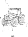
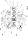
- reference number 1 indicates a tractor in its entirety.
- the tractor 1 comprises drive means, specifically for the movement of the tractor, for example, comprising an internal combustion engine, including the related transmission means for the transmission of motion to the wheel assemblies.
- the tractor 1 comprises a steering axle 2 connectable to or comprising said transmission means, in other words the steering axle 2 is a drive axle.
- the axle 2 extends along an axle axis A-A, typically transverse, i.e., perpendicular to the longitudinal axis of movement of the tractor 1.
- said steering axle 2 is the front axle of the tractor 1, as shown in Figure 1 .
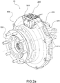
- the present invention relates to a wheel carrier assembly 10 of a vehicle for agricultural use such as the tractor 1 referred to above.
- the wheel carrier assembly 10 is connectable to the axle 2 to support and control in motion a wheel assembly fixed to it on a wheel flange 500.
- the wheel carrier assembly 10 connected comprises a constant-velocity joint 100 connected, upstream, to the transmission means, and comprising, downstream, a rotation shaft 101 for the rotation of the wheel assembly.
- the constant-velocity assembly 100 By means of the constant-velocity assembly 100, the steering of the wheel carrier assembly 10 is thus allowed, ensuring the motility of the wheel.
- the constant-velocity joint 10 is suitable to transmit a rotary motion to the rotation shaft 101; in particular, the speed transmitted by the transmission means, specifically by the differential, is transmitted as input to the constant-velocity joint; thanks to the constant-velocity joint 101 such transmission occurs by allowing the misalignment of their axes of rotation.
- the present invention is not limited to the type of constant-velocity joint 10 or to the arrangement of the constant-velocity joint 10, for example constituted by a cardan joint or more than one.
- the wheel carrier assembly 10 also comprises a gear reducer 300 connected to the wheel assembly and to the rotation shaft 101, suitable to vary the rotation speed of the rotation shaft 101.
- a gear reducer 300 connected to the wheel assembly and to the rotation shaft 101, suitable to vary the rotation speed of the rotation shaft 101.
- the revolutions, and thus the rotation speed, of the kinematic chain comprising the transmission means are provided in high numbers, and are then reduced by the gear reducer itself, before arriving to the respective wheel assembly.
- the rotation shaft 101 is the input shaft of the gear reducer 300, also known as "sun gear”.
- the gear reducer 300 is a planetary gear reducer.
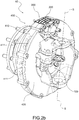
- the wheel carrier assembly 10 also comprises a disc brake device 200 suitable to brake the wheel assembly.
- the disc brake device 200 comprises at least one brake disc 210 and at least one brake calliper 220.
- the disk brake 210 is operatively connected to the shaft 101, upstream the gear reducer 300, so that the braking action is applied directly to said shaft 101.
- the braking action is performed through the disc brake device 200 upstream of the gear reducer 300.
- the brake disc 210 is integrally fixed to the rotation shaft 101, so as to discharge its action as much as possible and as effectively as possible on the rotation shaft 101.
- the rotation shaft 101 and the brake disc 210 are constrained in rotation to each other by locking means.
- the locking means comprise locking pins or locking keys such as to allow an angular locking of the disc brake 210 on the shaft.
- the locking means comprise a shaft toothing 101' and a brake toothing 210' respectively made on the rotation shaft 101 and on the brake disc 210 respectively complementary to each other, for the threading of the brake disc 210 onto the rotation shaft 101 in the axial direction. In this manner, an angular locking is guaranteed between the two components of a multiplicity of points, angularly equidistant.
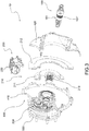
- the brake disc 210 comprises a shaft portion 211 engaged with the rotation shaft 101 and a braking band portion 212 on which the brake calliper 220 acts, mutually integrally connected.
- the shaft portion 211 and the braking band portion 212 are connected to each other by attachment means, such as screws.
- the brake disc 210 is designed in such a way that it is divided into two portions having specific purposes: the shaft portion 211 is suitable to engage the rotation shaft 101, for example comprising the brake toothing 210', while the braking band portion 212 is instead engaged by the brake calliper 220 and develops a braking action by friction.
- the shaft portion 211 is made of steel.
- the braking band portion 212 is made of a material suitable to ensure friction with the brake calliper 220, for example lamellar cast iron.
- the braking band portion 212 is a full, ventilated or petal component.
- the braking band portion 212 has a smooth, drilled, or perforated, slotted or segmental surface.
- the braking band portion 212 is replaceable, for example due to wear, by dismounting it from the shaft portion 211, which remains engaged to the rotation shaft 101.
- the braking band portion 212 is constituted in turn of several portions, so as to facilitate maintenance.
- the brake disc 210 is in one piece, and comprises the shaft portion 211 and the braking band potion 212.
- the shaft portion 211 and the rotation shaft 101 are made in one piece.
- the wheel carrier assembly 10 comprises a container body 400 comprising, mutually interconnected, a box-shaped portion 410 and a steering fork portion 420.
- box-shaped portion 410 is suitable to contain the gear reducer 300 and the brake disc 210.
- the steering fork portion 420 comprises seats 425 of a steering axis S-S, i.e., the axis of rotation around which the wheel carrier assembly 10, and thus the wheel assembly, is suitable to be moved in rotation, for example by the steering arm.
- a steering axis S-S i.e., the axis of rotation around which the wheel carrier assembly 10, and thus the wheel assembly, is suitable to be moved in rotation, for example by the steering arm.
- the seats 425 are housable the respective steering joints.
- the box-shaped portion 410 is a gear reducer box designed in such a way to be able to also house the brake disc 210.
- the brake calliper 220 is on board the container body 400, insertable on it radially, for example fixed to the box-shaped portion 410 or to the steering fork portion 420.
- the container body has radial ventilation openings 411, such as to permit the access of fresh air and the outlet of hot air from inside it, so as to avoid overheating of the brake disc 210.
- the wheel carrier assembly of the present invention allows achieving the intended purpose of the invention, i.e., to provide a wheel carrier assembly that easily placeable in the kinematic chain, connectable to a steering and drive axle, having an optimal braking capacity.
- this solution finds applications in slow-moving vehicles, such as vehicles for agricultural use such as a tractor. Due to the presence of low speeds, the solutions of the prior art with disc brake flanged to the wheel have ineffective braking: in fact, the low speeds of the vehicle give rise to low peripheral speeds between the disc brake and brake calliper, which as a consequence have problems in braking progressivity.
- the solution of the present invention by acting at high speeds, namely those input to the gear reducer, has better braking progressivity.
- the benefit of increased braking capacity is also obtained.
- the brake disc has small dimensions so as to be easily accommodated in the container body of the wheel carrier.
- a further advantage resides in the fact that, compared to solutions of the known art with oil bath braking systems inside the wheel carrier assembly, the solution of the present invention significantly reduces power absorption.
- a still further advantage resides in the fact that, in the solution of the present invention, the brake does not transmit energy or heat the oil in the gear reducer, as instead is the case in the aforesaid known solutions with oil bath braking systems, causing deducible damage to the functioning of the gear reducer.
- the braking of a disc brake is easily modulable as a function of the requested need.
- the action of the brake disc is controllable and easily modulable by means of the brake calliper.
- the constant-velocity joint is not affected by the braking forces.
- the constant-velocity joint and thus even more so in a configuration in which the wheel assembly is steered, is not stressed by the braking action occurring downstream of it.
- the constant-velocity joint is therefore smaller in size, but sufficient to withstand the action of the traction torque.
- the wheel carrier assembly is suitable to be applied on tractors, and in particular, is extraordinary effective in solutions in which it is applied to the front axles.
- the wheel carrier assembly finds specific application on front axles, bringing all the above advantages to them.
- a further advantage resides in the fact that, on the tractor, the movement of the braking distribution to the front axle, i.e., the transmission of the braking action from the rear axis to the front axis through the kinematic chain, can be minimised or actually avoided.
- total braking capacity distributed up to 70% to the front are achievable.
- a further advantage thus lies in the fact that, at the front axle the tractor has a particular braking readiness, for example the braking on the front wheels is manageable in such a way that it is contemporary or even takes place prior to the braking on the rear wheels.
- Yet another advantage can thus be foreseen in a possible reduction of the dimensions of brakes at the rear axle of the tractor.
Landscapes
- Engineering & Computer Science (AREA)
- Mechanical Engineering (AREA)
- General Engineering & Computer Science (AREA)
- Chemical & Material Sciences (AREA)
- Combustion & Propulsion (AREA)
- Transportation (AREA)
- Braking Arrangements (AREA)
- Gear Transmission (AREA)
Claims (12)
- Radträgeranordnung (10) eines Fahrzeugs zur landwirtschaftlichen Verwendung, beispielsweise eines Traktors, wobei das Fahrzeug Antriebsmittel, welche Mittel zur Übertragung umfassen, und eine Lenkachse (2) aufweist, welche mit den Antriebsmitteln verbindbar ist, wobei die Radträgeranordnung (10) mit der Achse (2) verbindbar ist, um eine daran an einem Radflansch (500) angebrachte Radanordnung zu haltern und bezüglich einer Bewegung zu steuern, wobei die Radträgeranordnung (10) umfasst:- ein Gleichlaufgelenk (100), welches stromaufwärts mit den Übertragungsmitteln verbunden ist und stromabwärts eine Rotationswelle (101) für die Rotation der Radanordnung umfasst;- eine Scheibenbremsenvorrichtung (200), welche dazu geeignet ist, die Radanordnung zu bremsen;- ein Getriebe für eine Übersetzung ins Langsame (300), welches mit der Radanordnung und der Rotationswelle (101) verbunden ist und dazu geeignet ist, die Rotationsgeschwindigkeit der Rotationswelle (101) zu variieren;wobei die Scheibenbremsenvorrichtung (200) wenigstens eine Bremsscheibe (210) und wenigstens einen Bremssattel (220) umfasst,
dadurch gekennzeichnet, dass die wenigstens eine Bremsscheibe (210) betriebsmäßig mit der Rotationswelle (101), stromaufwärts des Getriebes für eine Übersetzung ins Langsame (300), verbunden ist, so dass die Bremswirkung unmittelbar auf die Welle (101) ausgeübt wird. - Radträgeranordnung (10) nach Anspruch 1, wobei die wenigstens eine Bremsscheibe (210) integral an der Rotationswelle (101) angebracht ist.
- Radträgeranordnung (10) nach einem der vorhergehenden Ansprüche, wobei die Rotationswelle (101) und die wenigstens eine Bremsscheibe (210) durch Verriegelungsmittel bezüglich einer Drehung in Zwangsverbindung stehen.
- Radträgeranordnung (10) nach Anspruch 3, wobei die Verriegelungsmittel eine Wellenverzahnung (101') und eine Bremsenverzahnung (210') umfassen, welche an der Rotationswelle (101) bzw. an der wenigstens einen Bremsscheibe (210) jeweils zueinander komplementär gebildet sind, um die wenigstens eine Scheibenbremse (210) in der axialen Richtung an der Rotationswelle (101) in Eingriff zu bringen.
- Radträgeranordnung (10) nach einem der vorhergehenden Ansprüche, wobei die wenigstens eine Bremsscheibe (210) einen Wellenabschnitt (211), welcher mit der Rotationswelle (101) in Eingriff gebracht ist, und einen Bremsbandabschnitt (212) umfasst, auf welchen der wenigstens eine Bremssattel (220) einwirkt, integral miteinander verbunden.
- Radträgeranordnung (10) nach Anspruch 4, wobei der Wellenabschnitt (211) und der Bremsbandabschnitt (212) durch Anbringungsmittel, beispielsweise Schrauben, miteinander verbunden sind.
- Radträgeranordnung (10) nach den Ansprüchen 5 oder 6 in Kombination mit den Ansprüchen 1 oder 2, wobei der Wellenabschnitt (211) und die Rotationswelle (101) einstückig ausgebildet sind.
- Radträgeranordnung (10) nach einem der vorhergehenden Ansprüche, welche einen Behälterkörper (400) aufweist, umfassend miteinander verbunden:- einen kastenförmigen Abschnitt (410), welcher dazu geeignet ist, das Getriebe für eine Übersetzung ins Langsame (300) und die wenigstens eine Bremsscheibe (210) zu enthalten;- einen Lenkgabelabschnitt (420), welcher Sitze (425) einer Lenkachse (S-S) umfasst.
- Radträgeranordnung (10) nach Anspruch 8, wobei sich der wenigstens eine Bremssattel (220) innerhalb des Behälterkörpers (400) befindet.
- Radträgeranordnung (10) nach einem der Ansprüche 8 und 9, wobei der wenigstens eine Bremssattel (220) an dem Lenkgabelabschnitt (420) angebracht ist.
- Traktor (1), umfassend eine Lenkachse (2), welche Übertragungsmittel der Bewegung umfasst, mit welchen gelenkte Räder mittels einer Radträgeranordnung (10) gemäß einem der vorhergehenden Ansprüche verbunden sind.
- Traktor nach Anspruch 11, wobei die Achse (2) die Vorderachse ist.
Applications Claiming Priority (2)
| Application Number | Priority Date | Filing Date | Title |
|---|---|---|---|
| ITBS20150025 | 2015-02-24 | ||
| PCT/IB2016/050974 WO2016135629A1 (en) | 2015-02-24 | 2016-02-23 | Wheel carrier assembly with disk brake |
Publications (2)
| Publication Number | Publication Date |
|---|---|
| EP3261852A1 EP3261852A1 (de) | 2018-01-03 |
| EP3261852B1 true EP3261852B1 (de) | 2021-06-02 |
Family
ID=53016647
Family Applications (1)
| Application Number | Title | Priority Date | Filing Date |
|---|---|---|---|
| EP16715878.1A Active EP3261852B1 (de) | 2015-02-24 | 2016-02-23 | Radträgeranordnung mit scheibenbremse |
Country Status (5)
| Country | Link |
|---|---|
| US (1) | US10336136B2 (de) |
| EP (1) | EP3261852B1 (de) |
| JP (1) | JP6672338B2 (de) |
| CN (1) | CN107532661B (de) |
| WO (1) | WO2016135629A1 (de) |
Families Citing this family (7)
| Publication number | Priority date | Publication date | Assignee | Title |
|---|---|---|---|---|
| CN108528137B (zh) * | 2018-04-09 | 2019-09-10 | 上汽通用汽车有限公司 | 车轮组件 |
| US10828952B2 (en) * | 2018-12-04 | 2020-11-10 | Cnh Industrial America Llc | Suspension system for a work vehicle |
| IT201900000112A1 (it) * | 2019-01-07 | 2020-07-07 | Invaction S R L | Assieme per un veicolo e veicolo comprendente detto assieme |
| DE102019113939A1 (de) | 2019-05-24 | 2020-11-26 | Knorr-Bremse Systeme für Nutzfahrzeuge GmbH | Achsschenkel eines Nutzfahrzeuges |
| DE102019113942A1 (de) | 2019-05-24 | 2020-11-26 | Knorr-Bremse Systeme für Nutzfahrzeuge GmbH | Achsschenkel eines Nutzfahrzeuges, Achsanordnung und Fahrzeugachse eines Nutzfahrzeugs |
| CN111231579B (zh) * | 2020-01-15 | 2021-02-26 | 西华大学 | 一种全轮驱动式电动客车转向驱动桥 |
| CN115352414A (zh) * | 2022-08-17 | 2022-11-18 | 陕西汉德车桥有限公司 | 一种商用车辅助制动装置 |
Family Cites Families (11)
| Publication number | Priority date | Publication date | Assignee | Title |
|---|---|---|---|---|
| ES431037A1 (es) * | 1974-10-15 | 1976-10-16 | Kirkstall Forge Eng Ltd | Perfeccionamientos en ejes accionados para vehiculos de mo-tor. |
| IT8122224U1 (it) * | 1981-06-30 | 1982-12-30 | Same Spa | Trattrice agricola a quattro ruote motrici con impianto frenante perfezionato |
| JPH0613019Y2 (ja) * | 1987-03-31 | 1994-04-06 | 株式会社豊田自動織機製作所 | 産業車両用のデイスクブレ−キ装置 |
| JPH0512505Y2 (de) * | 1987-06-04 | 1993-03-31 | ||
| EP1433584A1 (de) | 2002-12-27 | 2004-06-30 | Kabushikikaisha Yaita Seisakusho | Kunststoffflasche und Verfahren zur deren Herstellung |
| US9410587B2 (en) * | 2012-04-07 | 2016-08-09 | Toyota Jidosha Kabushiki Kaisha | Friction brake device |
| DE102013206545B4 (de) * | 2013-04-12 | 2021-09-02 | Kessler & Co. Gmbh & Co. Kg | Lenkbare Radseite einer Antriebsachse |
| KR20140142479A (ko) * | 2013-06-04 | 2014-12-12 | 주식회사 만도 | 인휠 모터 시스템 |
| AU2017229614B2 (en) * | 2016-03-09 | 2019-02-14 | Hendrickson Usa, L.L.C. | Apparatus for mounting an air disc brake actuator |
| US10052913B2 (en) * | 2016-11-09 | 2018-08-21 | Arvinmeritor Technology, Llc | Wheel end assembly having a seal interface with a tone ring |
| US10093356B2 (en) * | 2017-02-21 | 2018-10-09 | Arvinmeritor Technology, Llc | Suspension system |
-
2016
- 2016-02-23 EP EP16715878.1A patent/EP3261852B1/de active Active
- 2016-02-23 US US15/552,983 patent/US10336136B2/en active Active
- 2016-02-23 WO PCT/IB2016/050974 patent/WO2016135629A1/en not_active Ceased
- 2016-02-23 JP JP2017562146A patent/JP6672338B2/ja not_active Expired - Fee Related
- 2016-02-23 CN CN201680011501.7A patent/CN107532661B/zh active Active
Also Published As
| Publication number | Publication date |
|---|---|
| JP6672338B2 (ja) | 2020-03-25 |
| JP2018508419A (ja) | 2018-03-29 |
| US20180015782A1 (en) | 2018-01-18 |
| US10336136B2 (en) | 2019-07-02 |
| WO2016135629A1 (en) | 2016-09-01 |
| CN107532661B (zh) | 2019-05-07 |
| CN107532661A (zh) | 2018-01-02 |
| EP3261852A1 (de) | 2018-01-03 |
Similar Documents
| Publication | Publication Date | Title |
|---|---|---|
| EP3261852B1 (de) | Radträgeranordnung mit scheibenbremse | |
| US11498410B2 (en) | Powered axle for dual wheel work vehicle | |
| US9636999B2 (en) | In-wheel assembly and vehicle with the in-wheel assembly | |
| EP3357730B1 (de) | Radnabenmotor | |
| EP3437913B1 (de) | Achsaggregat mit einer vorgelegewelle | |
| US11428302B1 (en) | Axle drive | |
| EP3321529A1 (de) | Radendanordnung mit einer dichtungsschnittstelle mit einem tonring | |
| US20130175776A1 (en) | Apparatus for adjusting camber and/or toe of wheels of suspensions | |
| CN105539131B (zh) | 用于机动车辆的液压驱动及其操作方法 | |
| US12172612B2 (en) | Axle assembly having a differential brake | |
| US8047337B2 (en) | Wheel brake for a vehicle and a vehicle comprising the wheel brake | |
| JP4967789B2 (ja) | 車輪駆動装置 | |
| US11827092B2 (en) | Vehicle with front-wheel-assist system | |
| JPH11315905A (ja) | デファレンシャル装置 | |
| CN114729681B (zh) | 齿轮减速组件 | |
| KR20200128573A (ko) | 브레이크 장치 | |
| JP2011105021A (ja) | 車両用最終減速装置のケース構造 | |
| WO2016026519A1 (en) | Differential gear arrangement | |
| KR101876886B1 (ko) | 농용 작업차의 뒷차축 케이스 및 이를 포함하는 농용 작업차의 뒷차축 조합 | |
| WO2017170588A1 (ja) | 伝動装置 | |
| EP4541630A1 (de) | Verbesserte elektrische achse | |
| JPH0587402B2 (de) | ||
| EP3657035B1 (de) | Gelenk- und kupplungsanordnung | |
| RU31225U1 (ru) | Механизм поворота транспортного средства | |
| RU2625216C2 (ru) | Компоновка органов торможения, трансмиссии и сцепления в транспортном средстве |
Legal Events
| Date | Code | Title | Description |
|---|---|---|---|
| STAA | Information on the status of an ep patent application or granted ep patent |
Free format text: STATUS: THE INTERNATIONAL PUBLICATION HAS BEEN MADE |
|
| PUAI | Public reference made under article 153(3) epc to a published international application that has entered the european phase |
Free format text: ORIGINAL CODE: 0009012 |
|
| STAA | Information on the status of an ep patent application or granted ep patent |
Free format text: STATUS: REQUEST FOR EXAMINATION WAS MADE |
|
| 17P | Request for examination filed |
Effective date: 20170804 |
|
| AK | Designated contracting states |
Kind code of ref document: A1 Designated state(s): AL AT BE BG CH CY CZ DE DK EE ES FI FR GB GR HR HU IE IS IT LI LT LU LV MC MK MT NL NO PL PT RO RS SE SI SK SM TR |
|
| AX | Request for extension of the european patent |
Extension state: BA ME |
|
| DAV | Request for validation of the european patent (deleted) | ||
| DAX | Request for extension of the european patent (deleted) | ||
| REG | Reference to a national code |
Ref country code: DE Ref legal event code: R079 Ref document number: 602016058779 Country of ref document: DE Free format text: PREVIOUS MAIN CLASS: B60B0035000000 Ipc: B60B0035120000 |
|
| GRAP | Despatch of communication of intention to grant a patent |
Free format text: ORIGINAL CODE: EPIDOSNIGR1 |
|
| STAA | Information on the status of an ep patent application or granted ep patent |
Free format text: STATUS: GRANT OF PATENT IS INTENDED |
|
| RIC1 | Information provided on ipc code assigned before grant |
Ipc: B60T 1/06 20060101ALI20210203BHEP Ipc: F16D 65/18 20060101ALN20210203BHEP Ipc: F16D 65/02 20060101ALN20210203BHEP Ipc: B60K 17/04 20060101ALI20210203BHEP Ipc: B60B 35/00 20060101ALI20210203BHEP Ipc: B60B 35/12 20060101AFI20210203BHEP Ipc: F16D 55/00 20060101ALI20210203BHEP Ipc: B60B 35/16 20060101ALI20210203BHEP |
|
| INTG | Intention to grant announced |
Effective date: 20210218 |
|
| GRAS | Grant fee paid |
Free format text: ORIGINAL CODE: EPIDOSNIGR3 |
|
| GRAA | (expected) grant |
Free format text: ORIGINAL CODE: 0009210 |
|
| STAA | Information on the status of an ep patent application or granted ep patent |
Free format text: STATUS: THE PATENT HAS BEEN GRANTED |
|
| REG | Reference to a national code |
Ref country code: CH Ref legal event code: EP |
|
| AK | Designated contracting states |
Kind code of ref document: B1 Designated state(s): AL AT BE BG CH CY CZ DE DK EE ES FI FR GB GR HR HU IE IS IT LI LT LU LV MC MK MT NL NO PL PT RO RS SE SI SK SM TR |
|
| REG | Reference to a national code |
Ref country code: GB Ref legal event code: FG4D |
|
| REG | Reference to a national code |
Ref country code: AT Ref legal event code: REF Ref document number: 1398089 Country of ref document: AT Kind code of ref document: T Effective date: 20210615 |
|
| REG | Reference to a national code |
Ref country code: IE Ref legal event code: FG4D |
|
| REG | Reference to a national code |
Ref country code: DE Ref legal event code: R096 Ref document number: 602016058779 Country of ref document: DE |
|
| REG | Reference to a national code |
Ref country code: LT Ref legal event code: MG9D |
|
| PG25 | Lapsed in a contracting state [announced via postgrant information from national office to epo] |
Ref country code: FI Free format text: LAPSE BECAUSE OF FAILURE TO SUBMIT A TRANSLATION OF THE DESCRIPTION OR TO PAY THE FEE WITHIN THE PRESCRIBED TIME-LIMIT Effective date: 20210602 Ref country code: LT Free format text: LAPSE BECAUSE OF FAILURE TO SUBMIT A TRANSLATION OF THE DESCRIPTION OR TO PAY THE FEE WITHIN THE PRESCRIBED TIME-LIMIT Effective date: 20210602 Ref country code: HR Free format text: LAPSE BECAUSE OF FAILURE TO SUBMIT A TRANSLATION OF THE DESCRIPTION OR TO PAY THE FEE WITHIN THE PRESCRIBED TIME-LIMIT Effective date: 20210602 Ref country code: BG Free format text: LAPSE BECAUSE OF FAILURE TO SUBMIT A TRANSLATION OF THE DESCRIPTION OR TO PAY THE FEE WITHIN THE PRESCRIBED TIME-LIMIT Effective date: 20210902 |
|
| REG | Reference to a national code |
Ref country code: NL Ref legal event code: MP Effective date: 20210602 |
|
| REG | Reference to a national code |
Ref country code: AT Ref legal event code: MK05 Ref document number: 1398089 Country of ref document: AT Kind code of ref document: T Effective date: 20210602 |
|
| PG25 | Lapsed in a contracting state [announced via postgrant information from national office to epo] |
Ref country code: LV Free format text: LAPSE BECAUSE OF FAILURE TO SUBMIT A TRANSLATION OF THE DESCRIPTION OR TO PAY THE FEE WITHIN THE PRESCRIBED TIME-LIMIT Effective date: 20210602 Ref country code: GR Free format text: LAPSE BECAUSE OF FAILURE TO SUBMIT A TRANSLATION OF THE DESCRIPTION OR TO PAY THE FEE WITHIN THE PRESCRIBED TIME-LIMIT Effective date: 20210903 Ref country code: RS Free format text: LAPSE BECAUSE OF FAILURE TO SUBMIT A TRANSLATION OF THE DESCRIPTION OR TO PAY THE FEE WITHIN THE PRESCRIBED TIME-LIMIT Effective date: 20210602 Ref country code: SE Free format text: LAPSE BECAUSE OF FAILURE TO SUBMIT A TRANSLATION OF THE DESCRIPTION OR TO PAY THE FEE WITHIN THE PRESCRIBED TIME-LIMIT Effective date: 20210602 Ref country code: PL Free format text: LAPSE BECAUSE OF FAILURE TO SUBMIT A TRANSLATION OF THE DESCRIPTION OR TO PAY THE FEE WITHIN THE PRESCRIBED TIME-LIMIT Effective date: 20210602 Ref country code: NO Free format text: LAPSE BECAUSE OF FAILURE TO SUBMIT A TRANSLATION OF THE DESCRIPTION OR TO PAY THE FEE WITHIN THE PRESCRIBED TIME-LIMIT Effective date: 20210902 |
|
| PG25 | Lapsed in a contracting state [announced via postgrant information from national office to epo] |
Ref country code: SK Free format text: LAPSE BECAUSE OF FAILURE TO SUBMIT A TRANSLATION OF THE DESCRIPTION OR TO PAY THE FEE WITHIN THE PRESCRIBED TIME-LIMIT Effective date: 20210602 Ref country code: SM Free format text: LAPSE BECAUSE OF FAILURE TO SUBMIT A TRANSLATION OF THE DESCRIPTION OR TO PAY THE FEE WITHIN THE PRESCRIBED TIME-LIMIT Effective date: 20210602 Ref country code: EE Free format text: LAPSE BECAUSE OF FAILURE TO SUBMIT A TRANSLATION OF THE DESCRIPTION OR TO PAY THE FEE WITHIN THE PRESCRIBED TIME-LIMIT Effective date: 20210602 Ref country code: CZ Free format text: LAPSE BECAUSE OF FAILURE TO SUBMIT A TRANSLATION OF THE DESCRIPTION OR TO PAY THE FEE WITHIN THE PRESCRIBED TIME-LIMIT Effective date: 20210602 Ref country code: AT Free format text: LAPSE BECAUSE OF FAILURE TO SUBMIT A TRANSLATION OF THE DESCRIPTION OR TO PAY THE FEE WITHIN THE PRESCRIBED TIME-LIMIT Effective date: 20210602 Ref country code: RO Free format text: LAPSE BECAUSE OF FAILURE TO SUBMIT A TRANSLATION OF THE DESCRIPTION OR TO PAY THE FEE WITHIN THE PRESCRIBED TIME-LIMIT Effective date: 20210602 Ref country code: PT Free format text: LAPSE BECAUSE OF FAILURE TO SUBMIT A TRANSLATION OF THE DESCRIPTION OR TO PAY THE FEE WITHIN THE PRESCRIBED TIME-LIMIT Effective date: 20211004 Ref country code: NL Free format text: LAPSE BECAUSE OF FAILURE TO SUBMIT A TRANSLATION OF THE DESCRIPTION OR TO PAY THE FEE WITHIN THE PRESCRIBED TIME-LIMIT Effective date: 20210602 Ref country code: ES Free format text: LAPSE BECAUSE OF FAILURE TO SUBMIT A TRANSLATION OF THE DESCRIPTION OR TO PAY THE FEE WITHIN THE PRESCRIBED TIME-LIMIT Effective date: 20210602 |
|
| REG | Reference to a national code |
Ref country code: DE Ref legal event code: R097 Ref document number: 602016058779 Country of ref document: DE |
|
| PLBE | No opposition filed within time limit |
Free format text: ORIGINAL CODE: 0009261 |
|
| STAA | Information on the status of an ep patent application or granted ep patent |
Free format text: STATUS: NO OPPOSITION FILED WITHIN TIME LIMIT |
|
| PG25 | Lapsed in a contracting state [announced via postgrant information from national office to epo] |
Ref country code: DK Free format text: LAPSE BECAUSE OF FAILURE TO SUBMIT A TRANSLATION OF THE DESCRIPTION OR TO PAY THE FEE WITHIN THE PRESCRIBED TIME-LIMIT Effective date: 20210602 |
|
| 26N | No opposition filed |
Effective date: 20220303 |
|
| PG25 | Lapsed in a contracting state [announced via postgrant information from national office to epo] |
Ref country code: AL Free format text: LAPSE BECAUSE OF FAILURE TO SUBMIT A TRANSLATION OF THE DESCRIPTION OR TO PAY THE FEE WITHIN THE PRESCRIBED TIME-LIMIT Effective date: 20210602 |
|
| PG25 | Lapsed in a contracting state [announced via postgrant information from national office to epo] |
Ref country code: MC Free format text: LAPSE BECAUSE OF FAILURE TO SUBMIT A TRANSLATION OF THE DESCRIPTION OR TO PAY THE FEE WITHIN THE PRESCRIBED TIME-LIMIT Effective date: 20210602 |
|
| REG | Reference to a national code |
Ref country code: CH Ref legal event code: PL |
|
| REG | Reference to a national code |
Ref country code: BE Ref legal event code: MM Effective date: 20220228 |
|
| GBPC | Gb: european patent ceased through non-payment of renewal fee |
Effective date: 20220223 |
|
| PG25 | Lapsed in a contracting state [announced via postgrant information from national office to epo] |
Ref country code: LU Free format text: LAPSE BECAUSE OF NON-PAYMENT OF DUE FEES Effective date: 20220223 |
|
| PG25 | Lapsed in a contracting state [announced via postgrant information from national office to epo] |
Ref country code: LI Free format text: LAPSE BECAUSE OF NON-PAYMENT OF DUE FEES Effective date: 20220228 Ref country code: IE Free format text: LAPSE BECAUSE OF NON-PAYMENT OF DUE FEES Effective date: 20220223 Ref country code: GB Free format text: LAPSE BECAUSE OF NON-PAYMENT OF DUE FEES Effective date: 20220223 Ref country code: CH Free format text: LAPSE BECAUSE OF NON-PAYMENT OF DUE FEES Effective date: 20220228 |
|
| PG25 | Lapsed in a contracting state [announced via postgrant information from national office to epo] |
Ref country code: BE Free format text: LAPSE BECAUSE OF NON-PAYMENT OF DUE FEES Effective date: 20220228 |
|
| P01 | Opt-out of the competence of the unified patent court (upc) registered |
Effective date: 20230526 |
|
| PG25 | Lapsed in a contracting state [announced via postgrant information from national office to epo] |
Ref country code: HU Free format text: LAPSE BECAUSE OF FAILURE TO SUBMIT A TRANSLATION OF THE DESCRIPTION OR TO PAY THE FEE WITHIN THE PRESCRIBED TIME-LIMIT; INVALID AB INITIO Effective date: 20160223 |
|
| PG25 | Lapsed in a contracting state [announced via postgrant information from national office to epo] |
Ref country code: MK Free format text: LAPSE BECAUSE OF FAILURE TO SUBMIT A TRANSLATION OF THE DESCRIPTION OR TO PAY THE FEE WITHIN THE PRESCRIBED TIME-LIMIT Effective date: 20210602 Ref country code: CY Free format text: LAPSE BECAUSE OF FAILURE TO SUBMIT A TRANSLATION OF THE DESCRIPTION OR TO PAY THE FEE WITHIN THE PRESCRIBED TIME-LIMIT Effective date: 20210602 |
|
| PG25 | Lapsed in a contracting state [announced via postgrant information from national office to epo] |
Ref country code: MT Free format text: LAPSE BECAUSE OF FAILURE TO SUBMIT A TRANSLATION OF THE DESCRIPTION OR TO PAY THE FEE WITHIN THE PRESCRIBED TIME-LIMIT Effective date: 20210602 |
|
| PG25 | Lapsed in a contracting state [announced via postgrant information from national office to epo] |
Ref country code: TR Free format text: LAPSE BECAUSE OF FAILURE TO SUBMIT A TRANSLATION OF THE DESCRIPTION OR TO PAY THE FEE WITHIN THE PRESCRIBED TIME-LIMIT Effective date: 20210602 |
|
| PGFP | Annual fee paid to national office [announced via postgrant information from national office to epo] |
Ref country code: DE Payment date: 20260223 Year of fee payment: 11 |
|
| PGFP | Annual fee paid to national office [announced via postgrant information from national office to epo] |
Ref country code: IT Payment date: 20251205 Year of fee payment: 11 |
|
| PGFP | Annual fee paid to national office [announced via postgrant information from national office to epo] |
Ref country code: FR Payment date: 20260130 Year of fee payment: 11 |