EP3260856A1 - Device for pretreatment of specimen and analyzer equipped therewith, and method for pretreatment of specimen - Google Patents
Device for pretreatment of specimen and analyzer equipped therewith, and method for pretreatment of specimen Download PDFInfo
- Publication number
- EP3260856A1 EP3260856A1 EP15882628.9A EP15882628A EP3260856A1 EP 3260856 A1 EP3260856 A1 EP 3260856A1 EP 15882628 A EP15882628 A EP 15882628A EP 3260856 A1 EP3260856 A1 EP 3260856A1
- Authority
- EP
- European Patent Office
- Prior art keywords
- reagent
- gas
- sample
- vessel
- supply part
- Prior art date
- Legal status (The legal status is an assumption and is not a legal conclusion. Google has not performed a legal analysis and makes no representation as to the accuracy of the status listed.)
- Granted
Links
Images


Classifications
-
- G—PHYSICS
- G01—MEASURING; TESTING
- G01N—INVESTIGATING OR ANALYSING MATERIALS BY DETERMINING THEIR CHEMICAL OR PHYSICAL PROPERTIES
- G01N33/00—Investigating or analysing materials by specific methods not covered by groups G01N1/00 - G01N31/00
- G01N33/48—Biological material, e.g. blood, urine; Haemocytometers
- G01N33/50—Chemical analysis of biological material, e.g. blood, urine; Testing involving biospecific ligand binding methods; Immunological testing
- G01N33/68—Chemical analysis of biological material, e.g. blood, urine; Testing involving biospecific ligand binding methods; Immunological testing involving proteins, peptides or amino acids
- G01N33/6803—General methods of protein analysis not limited to specific proteins or families of proteins
- G01N33/6818—Sequencing of polypeptides
- G01N33/6824—Sequencing of polypeptides involving N-terminal degradation, e.g. Edman degradation
-
- G—PHYSICS
- G01—MEASURING; TESTING
- G01N—INVESTIGATING OR ANALYSING MATERIALS BY DETERMINING THEIR CHEMICAL OR PHYSICAL PROPERTIES
- G01N1/00—Sampling; Preparing specimens for investigation
- G01N1/28—Preparing specimens for investigation including physical details of (bio-)chemical methods covered elsewhere, e.g. G01N33/50, C12Q
-
- G—PHYSICS
- G01—MEASURING; TESTING
- G01N—INVESTIGATING OR ANALYSING MATERIALS BY DETERMINING THEIR CHEMICAL OR PHYSICAL PROPERTIES
- G01N1/00—Sampling; Preparing specimens for investigation
- G01N1/28—Preparing specimens for investigation including physical details of (bio-)chemical methods covered elsewhere, e.g. G01N33/50, C12Q
- G01N1/34—Purifying; Cleaning
-
- G—PHYSICS
- G01—MEASURING; TESTING
- G01N—INVESTIGATING OR ANALYSING MATERIALS BY DETERMINING THEIR CHEMICAL OR PHYSICAL PROPERTIES
- G01N1/00—Sampling; Preparing specimens for investigation
- G01N1/28—Preparing specimens for investigation including physical details of (bio-)chemical methods covered elsewhere, e.g. G01N33/50, C12Q
- G01N1/38—Diluting, dispersing or mixing samples
-
- G—PHYSICS
- G01—MEASURING; TESTING
- G01N—INVESTIGATING OR ANALYSING MATERIALS BY DETERMINING THEIR CHEMICAL OR PHYSICAL PROPERTIES
- G01N30/00—Investigating or analysing materials by separation into components using adsorption, absorption or similar phenomena or using ion-exchange, e.g. chromatography or field flow fractionation
- G01N30/02—Column chromatography
- G01N30/04—Preparation or injection of sample to be analysed
-
- G—PHYSICS
- G01—MEASURING; TESTING
- G01N—INVESTIGATING OR ANALYSING MATERIALS BY DETERMINING THEIR CHEMICAL OR PHYSICAL PROPERTIES
- G01N33/00—Investigating or analysing materials by specific methods not covered by groups G01N1/00 - G01N31/00
- G01N33/48—Biological material, e.g. blood, urine; Haemocytometers
- G01N33/50—Chemical analysis of biological material, e.g. blood, urine; Testing involving biospecific ligand binding methods; Immunological testing
- G01N33/68—Chemical analysis of biological material, e.g. blood, urine; Testing involving biospecific ligand binding methods; Immunological testing involving proteins, peptides or amino acids
-
- G—PHYSICS
- G01—MEASURING; TESTING
- G01N—INVESTIGATING OR ANALYSING MATERIALS BY DETERMINING THEIR CHEMICAL OR PHYSICAL PROPERTIES
- G01N35/00—Automatic analysis not limited to methods or materials provided for in any single one of groups G01N1/00 - G01N33/00; Handling materials therefor
- G01N35/10—Devices for transferring samples or any liquids to, in, or from, the analysis apparatus, e.g. suction devices, injection devices
- G01N35/1009—Characterised by arrangements for controlling the aspiration or dispense of liquids
-
- G—PHYSICS
- G01—MEASURING; TESTING
- G01N—INVESTIGATING OR ANALYSING MATERIALS BY DETERMINING THEIR CHEMICAL OR PHYSICAL PROPERTIES
- G01N35/00—Automatic analysis not limited to methods or materials provided for in any single one of groups G01N1/00 - G01N33/00; Handling materials therefor
- G01N35/10—Devices for transferring samples or any liquids to, in, or from, the analysis apparatus, e.g. suction devices, injection devices
- G01N35/1095—Devices for transferring samples or any liquids to, in, or from, the analysis apparatus, e.g. suction devices, injection devices for supplying the samples to flow-through analysers
-
- C—CHEMISTRY; METALLURGY
- C07—ORGANIC CHEMISTRY
- C07K—PEPTIDES
- C07K1/00—General methods for the preparation of peptides, i.e. processes for the organic chemical preparation of peptides or proteins of any length
- C07K1/12—General methods for the preparation of peptides, i.e. processes for the organic chemical preparation of peptides or proteins of any length by hydrolysis, i.e. solvolysis in general
- C07K1/128—General methods for the preparation of peptides, i.e. processes for the organic chemical preparation of peptides or proteins of any length by hydrolysis, i.e. solvolysis in general sequencing
-
- G—PHYSICS
- G01—MEASURING; TESTING
- G01N—INVESTIGATING OR ANALYSING MATERIALS BY DETERMINING THEIR CHEMICAL OR PHYSICAL PROPERTIES
- G01N1/00—Sampling; Preparing specimens for investigation
- G01N1/28—Preparing specimens for investigation including physical details of (bio-)chemical methods covered elsewhere, e.g. G01N33/50, C12Q
- G01N1/38—Diluting, dispersing or mixing samples
- G01N2001/386—Other diluting or mixing processes
- G01N2001/387—Other diluting or mixing processes mixing by blowing a gas, bubbling
-
- G—PHYSICS
- G01—MEASURING; TESTING
- G01N—INVESTIGATING OR ANALYSING MATERIALS BY DETERMINING THEIR CHEMICAL OR PHYSICAL PROPERTIES
- G01N30/00—Investigating or analysing materials by separation into components using adsorption, absorption or similar phenomena or using ion-exchange, e.g. chromatography or field flow fractionation
- G01N30/02—Column chromatography
- G01N30/04—Preparation or injection of sample to be analysed
- G01N30/06—Preparation
- G01N2030/067—Preparation by reaction, e.g. derivatising the sample
-
- G—PHYSICS
- G01—MEASURING; TESTING
- G01N—INVESTIGATING OR ANALYSING MATERIALS BY DETERMINING THEIR CHEMICAL OR PHYSICAL PROPERTIES
- G01N30/00—Investigating or analysing materials by separation into components using adsorption, absorption or similar phenomena or using ion-exchange, e.g. chromatography or field flow fractionation
- G01N30/02—Column chromatography
- G01N30/04—Preparation or injection of sample to be analysed
- G01N30/06—Preparation
Definitions
- the present invention relates to a device for pretreatment of a sample which dissolves a sample in a reagent containing an organic solvent and introduced into a vessel, an analyzer equipped therewith, and a method for pretreatment of a sample.
- An amino acid sequence analyzer (protein sequencer) utilizing Edman degradation includes an Edman degradation part which configures a device for pretreatment of a sample.
- Edman degradation in the Edman degradation part causes amino acids to be eliminated from protein (including peptide) which is a target sample for an amino acid sequence analysis such that amino acid residues are eliminated one by one as derivatives of amino acids.
- Each amino acid eliminated from the protein sample due to Edman degradation is dissolved in a reagent within a vessel called a conversion flask, and then is introduced in a high-performance liquid chromatograph. In the high-performance liquid chromatograph, each amino acid in the reagent is separated while passing through a column and is sequentially detected by a detector, and thus, the amino-acid sequence is analyzed (for example, see Patent Document 1 listed below).
- Examples of a reagent used for dissolving a derivatized amino acid include an organic solvent such as acetonitrile, and a mixed solution of the organic solvent and water.
- concentration of the organic solvent is set to a predetermined value. Therefore, depending of the type of the column used in the high-performance liquid chromatograph connected to the device for pretreatment of a sample, concentration of the organic solvent may not be suitable for separation of an amino acid sample. For example, in a case where concentration of the organic solvent is high, an amino acid sample cannot be favorably separated, which may have an adverse effect on the
- Patent Document 1 JP 9-68534 A
- the amino acid sample may be dried by using a centrifugal concentrator, the dried amino acid sample may be dissolved again into another solvent suitable for separation, and measurement may be performed again.
- the amino acid sample is completely dried in a vessel, the amino acid is precipitated and is likely to adhere to an inner surface of the vessel. Therefore, there is a problem that when the dried amino acid sample is to be dissolved again in the solvent, some acids are not dissolved enough and sample loss occurs.
- the present invention is made in view of the above circumstances, and an object of the present invention is to provide a device for pretreatment of a sample which can prevent occurrence of sample loss and can easily and efficiently lower concentration of an organic solvent in a reagent, an analyzer equipped therewith, and a method for pretreatment of a sample.
- a device for pretreatment of a sample includes a vessel, a reagent introduction part, a reagent discharge part, a first gas supply part, and a second gas supply part.
- a vessel a reagent containing an organic solvent is introduced and a sample is dissolved in the reagent.
- the reagent introduction part introduces the reagent into the vessel.
- the reagent discharge part discharges the reagent in which the sample is dissolved in the vessel to an outside of the vessel.
- the first gas supply part supplies a gas into the vessel and thus pressurizes the interior of the vessel.
- the second gas supply part supplies a gas into the reagent in the vessel and thus forms gas bubbles in the reagent.
- a gas is supplied from the second gas supply part to the reagent in the vessel, and thus gas bubbles are formed in the reagent and volatilization of the organic solvent in the reagent is promoted by the gas bubbles. Therefore, concentration of the organic solvent in the reagent can be easily and efficiently lowered.
- concentration of the organic solvent in the reagent can be easily and efficiently lowered.
- the second gas supply part may supply a gas into the reagent in the vessel via the reagent discharge part.
- gas bubbles can be formed in the reagent. Since the reagent discharge part is usually configured to discharge a reagent from a bottom portion inside the vessel, gas bubbles can be formed from lower part of the reagent if a gas is supplied into the vessel via the reagent discharge part.
- gas bubbles can be favorably formed in the reagent in this manner, concentration of the organic solvent in the reagent can be efficiently lowered.
- concentration of the organic solvent in the reagent can be easily lowered without incurring a cost increase.
- the first gas supply part may supply a gas into the vessel via the reagent introduction part.
- the interior of the vessel can be pressurized.
- the reagent introduction part is usually configured to introduce a reagent into the vessel by pressure of a gas
- the interior of the vessel can be pressurized without newly adding a configuration if a gas is supplied into the vessel via the reagent introduction part.
- the first gas supply part may supply a gas from a supply source (for example, a gas cylinder) shared by the second gas supply part, or may supply a gas from a supply source different from the supply source of the second gas supply part.
- a common supply source may be used.
- different supply sources may be used.
- the device for pretreatment of a sample may further include a setting reception processing unit, and a gas supply control unit.
- the setting reception processing unit receives setting of a time period for supplying a gas from the second gas supply part.
- the gas supply control unit controls gas supply from the second gas supply part according to the set time period received by the setting reception processing unit.
- the time period for supplying a gas from the second gas supply part can be arbitrarily set, the time period for forming gas bubbles in the reagent can be adjusted by adjusting the set time period, and thus concentration of the organic solvent in the reagent can be arbitrarily adjusted.
- the gas supply control unit may be configured to control gas supply from the first gas supply part in addition to gas supply from the second gas supply part. In this case, the gas supply control unit may control gas supply from the first gas supply part according to the set time received by the setting reception processing unit.
- the device for pretreatment of a sample may further include a sample supply part where a protein sample is subjected to Edman degradation.
- a sample supply part where a protein sample is subjected to Edman degradation.
- an amino acid obtained by Edman degradation in the sample supply part may be introduced as a sample into the vessel.
- An analyzer includes the device for pretreatment of a sample, and a detector which detects a sample in a reagent discharged via the reagent discharge part.
- a method for pretreatment of a sample according to the present invention includes a dissolution step, a first gas supply step, and a second gas supply step.
- a dissolution step a reagent containing an organic solvent is introduced into a vessel, and a sample is dissolved in the reagent.
- a gas is supplied into the vessel, and thus the interior of the vessel is pressurized.
- a gas is supplied into the reagent in the vessel, and thus gas bubbles are formed in the reagent.
- volatilization of the organic solvent in the reagent is promoted by gas bubbles formed in the reagent. Therefore, concentration of the organic solvent in the reagent can be easily and efficiently lowered. In addition, since the sample does not adhere to the inner surface of the vessel, occurrence of sample loss can be prevented.
- FIG. 1 is a block diagram schematically illustrating a configuration example of an analyzer according to an embodiment of the present invention.
- the flow of a liquid and a gas is indicated by solid arrows, and the flow of electric signals is indicated by broken line arrows.
- the analyzer according to the present embodiment is an amino acid sequence analyzer (protein sequencer) which can utilize Edman degradation to eliminate amino acids from protein (including peptide) that is a target sample for a sequence analysis, and can analyze the amino acid sequence of the target protein (including peptide, the same applies hereinafter).
- the protein sequencer includes a device 1 for pretreatment of a sample, a high-performance liquid chromatograph (HPLC) 2, and a control device 3.
- HPLC high-performance liquid chromatograph
- the device 1 for pretreatment of a sample includes a conversion vessel 11, a sample supply part 12, a reagent supply part 13, a first gas supply part 14, a second gas supply part 15, and the like.
- the following process is performed.
- An amino acid is eliminated from a protein sample by Edman degradation in the sample supply part 12 and the eliminated amino acid sample is dissolved in a reagent in the conversion vessel 11.
- the conversion vessel 11 is a vessel made of, for example, glass.
- a sample (amino acid sample) is supplied to the conversion vessel 11 from the sample supply part 12, and a reagent is supplied to the conversion vessel 11 from the reagent supply part 13.
- the first gas supply part 14 supplies an inert gas such as nitrogen gas into the reagent supply part 13, and the pressure of the inert gas causes the reagent to be supplied from the reagent supply part 13.
- the gas supplied from the first gas supply part 14 is not limited to nitrogen gas as long as the gas is an inert gas, and may be another gas such as helium gas or argon gas.
- a protein sample held by a sample holder such as a glass fiber filter or a PVDF (polyvinylidene fluoride) membrane is set, and a reagent is supplied from the reagent supply part 13 to the protein sample.
- the reagent supplied from the reagent supply part 13 to the sample supply part 12 is a reagent necessary for Edman degradation.
- the reagent include ethyl acetate, n-butyl chloride, trimethylamine, a PITC n-heptane solution, and trifluoroacetic acid; however, the reagent is not limited to the above.
- the reagent supplied from the reagent supply part 13 is used to eliminate an amino acid from the protein sample by Edman degradation. Specifically, PTC-protein is generated by a coupling reaction and then the N-terminal amino acid of the PTC-protein is cleaved. Thus, the N-terminal amino acid of the protein sample is eliminated as an ATZ-amino acid.
- the eliminated ATZ-amino acid is supplied to the conversion vessel 11 via a sample introduction tube 16.
- the sample introduction tube 16 configures a sample introduction part for introducing the amino acid sample (ATZ-amino acid) into the conversion vessel 11.
- a reagent is introduced from the reagent supply part 13 via a reagent introduction tube 17 in the conversion vessel 11 into which the amino acid sample (ATZ-amino acid) is supplied.
- the reagent directly introduced into the conversion vessel 11 from the reagent supply part 13 is of a kind different from the reagent introduced to the sample supply part 12.
- Examples of the reagent necessary for a conversion reaction from an ATZ-amino acid to a PTH-amino acid include an organic solvent such as acetonitrile, and a mixed solution of the organic solvent and water.
- the reagent introduction tube 17 configures a reagent introduction part for introducing the reagent containing the organic solvent into the conversion vessel 11.
- the amino acid sample (ATZ-amino acid) introduced from the sample introduction tube 16 is stabilized, and then is dissolved in the reagent introduced from the reagent introduction tube 17, and is discharged to the HPLC 2 together with the reagent via a reagent discharge tube 18.
- the ATZ-amino acid is converted into a stable PTH-amino acid, and the PTH-amino acid is dissolved in the organic solvent or the mixed solution of the organic solvent and water.
- the reagent discharge tube 18 configures a reagent discharge part which discharges the reagent in which the amino acid sample (PTH-amino acid) is dissolved to the outside the conversion vessel 11.
- the HPLC 2 includes a column 21 and a detector 22.
- the reagent in which the amino acid sample (PTH-amino acid) is dissolved in the conversion vessel 11 is supplied from the device 1 for pretreatment of a sample to the column 21 via the reagent discharge tube 18, and a sample component is separated while the reagent passes through the column 21.
- Each sample component separated in the column 21 is detected by the detector 22.
- the detector 22 include an ultraviolet-visible detector (UV/VIS detector); however, the detector 22 is not limited to this, and may be another detector such as a photodiode array detector.
- a gas can be supplied from the first gas supply part 14 to the reagent supply part 13 and the reagent can be supplied from the reagent supply part 13.
- a gas can be directly supplied from the first gas supply part 14 to the reagent introduction tube 17 not through the reagent supply part 13. In this case, not the reagent but the gas is supplied through the reagent introduction tube 17 into the conversion vessel 11, and thus, the interior of the conversion vessel 11 can be pressurized.
- Such switchover of a gas supply manner can be performed, for example, by operating a flow channel switchover mechanism including a three-way valve.
- the second gas supply part 15 can supply a gas into the conversion vessel 11 via the reagent discharge tube 18.
- the gas supplied from the second gas supply part 15 is an inert gas such as nitrogen gas.
- the gas supplied from the second gas supply part 15 is not limited to nitrogen gas as long as the gas is an inert gas, and may be another gas such as helium gas or argon gas.
- the gas supplied from the second gas supply part 15 may be of the same kind as the gas supplied from the first gas supply part 14, or may be of a different kind.
- the pressure of the gas supplied from the first gas supply part 14 and the pressure of the gas supplied from the second gas supply part 15 are preferably set to values different from each other.
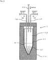
- FIG. 2 is a schematic cross-sectional view illustrating a configuration example around the conversion vessel 11.
- the conversion vessel 11 is accommodated in a state of being sealed in a heat block 111, and is heated to a set temperature (for example, about 60°C) by the heat block 111.
- a set temperature for example, about 60°C
- the heat block 111 can be omitted.
- Ends of the sample introduction tube 16, the reagent introduction tube 17, and the reagent discharge tube 18 are inserted into the conversion vessel 11.
- the ends of the sample introduction tube 16 and the reagent introduction tube 17 are located at an upper portion inside the conversion vessel 11, and are located higher than the liquid surface of the reagent 4 supplied into the conversion vessel 11.
- the end of the reagent discharge tube 18 is located at a bottom portion inside the conversion vessel 11, and is located lower than the liquid surface of the reagent 4 supplied into the conversion vessel 11. Note that even though not illustrated in FIG. 2 , an end of a vent tube for exhausting the gas in the conversion vessel 11 into atmosphere may be inserted into the conversion vessel 11.
- the amino acid sample (ATZ-amino acid) is introduced from the sample introduction tube 16 into the conversion vessel 11.
- the reagent 4 is introduced from the reagent introduction tube 17 into the conversion vessel 11, and therefore the amino acid sample is stabilized and the stabilized amino acid sample (PTH-amino acid) is dissolved in the reagent 4 at the bottom portion inside the conversion vessel 11.
- a gas is supplied from the first gas supply part 14 into the conversion vessel 11 via the reagent introduction tube 17, and thus air in space 112 above the reagent 4 in the conversion vessel 11 is pressurized.
- the reagent is discharged to the outside of the conversion vessel 11 from the reagent discharge tube 18. At that time, the reagent is discharged from the end of the reagent discharge tube 18 located at the bottom portion inside the conversion vessel 11, and therefore all of the reagent in the conversion vessel 11 can be discharged to the outside.
- a gas is supplied into the reagent 4 in the conversion vessel 11 from the second gas supply part 15, and thus gas bubbles 41 are formed in the reagent 4 and the gas bubbles 41 promote volatilization of the organic solvent in the reagent 4.
- the organic solvent is volatilized in the space 112 above the reagent 4 in the conversion vessel 11, and concentration of the organic solvent in the reagent 4 can be easily and efficiently lowered.
- differing from the configuration of completely drying an amino acid sample (PTH-amino acid) and then adding a solvent for a HPLC, which is a conventional method since the amino acid sample does not adhere to an inner surface of the conversion vessel 11, occurrence of sample loss can be prevented.
- a gas is supplied into the reagent 4 in the conversion vessel 11 via the reagent discharge tube 18 for discharging the reagent 4 in which the amino acid sample (PTH-amino acid) is dissolved to the outside of the conversion vessel 11, and therefore gas bubbles 41 can be formed in the reagent 4.
- the reagent discharge tube 18 is usually configured to discharge the reagent 4 from the bottom portion inside the conversion vessel 11 in the same manner as in the present embodiment, gas bubbles 41 can be formed from lower part of the reagent 4 if a gas is supplied into the conversion vessel 11 via the reagent discharge tube 18.
- gas bubbles 41 can be favorably formed in the reagent 4, concentration of the organic solvent in the reagent 4 can be efficiently lowered.
- concentration of the organic solvent in the reagent 4 can be easily lowered without incurring a cost increase.
- a gas is supplied into the conversion vessel 11 via the reagent introduction tube 17 for introducing the reagent 4 into the conversion vessel 11, and thus the interior of the conversion vessel 11 can be pressurized.
- the reagent introduction tube 17 is usually configured to introduce a reagent into the conversion vessel 11 by pressure of a gas in the same manner as in the present embodiment, the interior of the conversion vessel 11 can be pressurized without newly adding a configuration if a gas is supplied into the conversion vessel 11 via the reagent introduction tube 17.
- the control device 3 is configured of a computer, for example, and includes a control unit 31, an operation unit 32, a display unit 33, and the like.
- the control unit 31 is configured to include a CPU (Central Processing Unit), for example.
- the CPU executes a program, which causes the control unit 31 to function as a gas supply control unit 311, a setting reception processing unit 312, an analysis processing unit 313, or the like.
- the operation unit 32 is configured of, for example, a keyboard and a mouse, and an operator can perform various setting operations by using the operation unit 32.
- the display unit 33 is configured of, for example, a liquid crystal display, and the operator can confirm the operation settings and the operation status of the analyzer by viewing display of the display unit 33.
- the gas supply control unit 311 controls gas supply from the first gas supply part 14 and from the second gas supply part 15. Specifically, by controlling the opening or closing state of a valve (not illustrated) provided to each of the first gas supply part 14 and the second gas supply part 15, the gas supply state from each of the first gas supply part 14 and the second gas supply part 15 is switched over.
- the setting reception processing unit 312 receives settings regarding gas supply from the first gas supply part 14 and from the second gas supply part 15.
- the operator can set a time period for supplying a gas from each of the first gas supply part 14 and the second gas supply part 15 by operating the operation unit 32.
- the gas supply control unit 311 controls gas supply from each of the first gas supply part 14 and the second gas supply part 15 according to the set time period received by the setting reception processing unit 312 such that a gas is supplied only for the set time period.
- the time period for supplying a gas from the second gas supply part 15 can be arbitrarily set, the time period for forming gas bubbles 41 in the reagent 4 can be adjusted by adjusting the set time period, and concentration of the organic solvent in the reagent 4 can be arbitrarily adjusted.
- the interior of the conversion vessel 11 can be favorably pressurized in accordance with the time period for forming gas bubbles 41.
- the analysis processing unit 313 identifies each sample component separated while passing through the column 21 according to the detection signal from the detector 22, and analyzes the amino acid sequence of the target protein sample.
- the analysis result obtained by the analysis processing unit 313 is displayed on the display unit 33, and thus the operator is notified of the result.
- the analysis result obtained by the analysis processing unit 313 is not limited to the configuration in which the result is displayed on the display unit 33, and may be, for example, a configuration in which the result is output in another manner such as printing.
- FIG. 3A is a flowchart illustrating a flow of processes performed when a protein sample is analyzed by the analyzer illustrated in FIG. 1 .
- an analysis is started, first, the sample holder holding a protein sample is set in the sample supply part 12 (step S101), and then a coupling reaction is performed (step S102).
- trimethylamine is supplied from the reagent supply part 13 to the sample supply part 12, a reaction chamber of the sample supply part 12 is filled with trimethylamine (gas), and then, a PITC n-heptane solution is supplied from the reagent supply part 13 into the reaction chamber, the solution is reacted with an N-terminal amino group of protein, and thus PTC-protein is generated. Then, ethyl acetate is supplied from the reagent supply part 13 into the reaction chamber to wash out excess reagent and a by-product.
- trimethylamine is supplied from the reagent supply part 13 to the sample supply part 12
- a reaction chamber of the sample supply part 12 is filled with trimethylamine (gas)
- a PITC n-heptane solution is supplied from the reagent supply part 13 into the reaction chamber, the solution is reacted with an N-terminal amino group of protein, and thus PTC-protein is generated.
- ethyl acetate is supplied from the reagent supply part 13 into the
- step S103 cleavage reaction
- the eliminated ATZ-amino acid is extracted by supplying n-butyl chloride into the reaction chamber from the reagent supply part 13, and the extracted amino acid sample (ATZ-amino acid) is introduced into the conversion vessel 11 from the sample supply part 12 (step S104).
- step S105 a conversion reaction is performed in the conversion vessel 11 (step S105).
- a trifluoroacetic acid solution is introduced from the reagent supply part 13 into the conversion vessel 11, and thus the ATZ-amino acid is converted into a stable PTH-amino acid.
- a mixed solution of acetonitrile and water is supplied from the reagent supply part 13 into the conversion vessel 11, and thus the PTH-amino acid is dissolved in the mixed solution (step S106).
- This step S106 constitutes a dissolution step of dissolving the sample (amino acid sample) into the reagent 4 containing the organic solvent.
- a bubbling process as described with reference to FIG. 2 is performed for the reagent 4 in the conversion vessel 11 (step S107). Thereafter, the reagent 4 in the conversion vessel 11 is discharged from the reagent discharge tube 18 to the HPLC 2, and is injected into the column 21 of the HPLC 2 (step S108). The processes in steps S102 to S108 are repeated until the number of cycles set in advance is reached (Yes in step S109), and the amino acid sample (PTH-amino acid) separated in the column 21 is detected by the detector 22 (step S110). Then, the detection signal from the detector 22 is analyzed by the analysis processing unit 313, and thus data display and record, identification, quantification, yield calculation, or the like of the PTH-amino acid are performed (step S111).
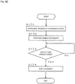
- FIG. 3B is a flowchart illustrating an example of the bubbling process.
- a gas is supplied from the first gas supply part 14 into the conversion vessel 11 via the reagent introduction tube 17, and thus the interior of the conversion vessel 11 is pressurized (step S171: first gas supply step).
- a gas is supplied from the second gas supply part 15 into the conversion vessel 11 via the reagent discharge tube 18, and thus gas bubbles 41 are formed in the reagent 4 in the conversion vessel 11 (step S172: second gas supply step). This state is maintained, and thus concentration of the organic solvent in the reagent 4 gradually lowers.
- step S174 gas supply stop step
- the reagent 4 is discharged from the reagent discharge tube 18 to the HPLC 2 (reagent discharge step).
- the time period for supplying a gas from the first gas supply part 14 and the time period for supplying a gas from the second gas supply part 15 may be identical or different from each other.
- the time period for supplying a gas from the first gas supply part 14 and the time period for supplying a gas from the second gas supply part 15 may be set separately. Alternatively, one of the time periods may be set first and then the other may be set with reference to the time period set first.
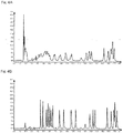
- FIG. 4A is a diagram illustrating the detection result in a case where an analysis of a protein sample was performed by using a conventional analyzer.
- FIG. 4B is a diagram illustrating the detection result in a case where an analysis of the protein sample was performed by using the analyzer according to the present invention.
- a gas was supplied for 24 seconds from the second gas supply part 15 into the conversion vessel 11 via the reagent discharge tube 18, thereby forming gas bubbles 41 in the reagent 4 in the conversion vessel 11 during that period.
- the sample introduction part which introduces an amino acid sample (ATZ-amino acid) into the conversion vessel 11 is configured of the sample introduction tube 16 inserted into the upper portion inside the conversion vessel 11; however, the sample introduction part is not limited to this.
- an amino acid sample may be introduced by using a member other than a tube.
- the reagent introduction part which introduces the reagent 4 into the conversion vessel 11 is not limited to the reagent introduction tube 17 inserted into the upper portion inside the conversion vessel 11.
- the reagent 4 may be introduced by using a member other than a tube.
- the reagent discharge part which discharges the reagent 4 from the conversion vessel 11 is not limited to the reagent discharge tube 18 inserted into the bottom portion inside the conversion vessel 11.
- the reagent 4 may be discharged by using a member other than a tube.
- the present invention is not limited to this.
- a configuration may be adopted where a gas is supplied into the conversion vessel 11 via a path provided separately from the reagent introduction tube 17.
- the present invention is not limited to the configuration where the first gas supply part 14 can supply a gas also to the reagent supply part 13.
- the first gas supply part 14 may be dedicated to pressurizing the interior of the conversion vessel 11.
- the present invention is not limited to the configuration where a gas is supplied from the second gas supply part 15 into the reagent 4 in the conversion vessel 11 via the reagent discharge tube 18.
- a configuration may be adopted where a gas is supplied into the reagent 4 in the conversion vessel 11 via a path separately provided from the reagent discharge tube 18.
- the present invention is not limited to be applied to a protein sequencer which analyzes a protein sample, and can be applied also to the device 1 for pretreatment of a sample included in another analyzer.
- the present invention is not limited to a device which automatically performs processing for a protein sample, such as a protein sequencer, and the present invention can also be applied to a configuration where at least some of the processes are performed manually by an operator.
Landscapes
- Life Sciences & Earth Sciences (AREA)
- Health & Medical Sciences (AREA)
- Chemical & Material Sciences (AREA)
- Immunology (AREA)
- Physics & Mathematics (AREA)
- Engineering & Computer Science (AREA)
- Analytical Chemistry (AREA)
- Biochemistry (AREA)
- General Health & Medical Sciences (AREA)
- General Physics & Mathematics (AREA)
- Pathology (AREA)
- Molecular Biology (AREA)
- Biomedical Technology (AREA)
- Hematology (AREA)
- Urology & Nephrology (AREA)
- Food Science & Technology (AREA)
- Microbiology (AREA)
- Proteomics, Peptides & Aminoacids (AREA)
- Cell Biology (AREA)
- Biotechnology (AREA)
- Medicinal Chemistry (AREA)
- Bioinformatics & Cheminformatics (AREA)
- Bioinformatics & Computational Biology (AREA)
- Biophysics (AREA)
- Investigating Or Analysing Biological Materials (AREA)
- Sampling And Sample Adjustment (AREA)
Abstract
Description
- The present invention relates to a device for pretreatment of a sample which dissolves a sample in a reagent containing an organic solvent and introduced into a vessel, an analyzer equipped therewith, and a method for pretreatment of a sample.
- An amino acid sequence analyzer (protein sequencer) utilizing Edman degradation includes an Edman degradation part which configures a device for pretreatment of a sample. In the protein sequencer, Edman degradation in the Edman degradation part causes amino acids to be eliminated from protein (including peptide) which is a target sample for an amino acid sequence analysis such that amino acid residues are eliminated one by one as derivatives of amino acids. Each amino acid eliminated from the protein sample due to Edman degradation is dissolved in a reagent within a vessel called a conversion flask, and then is introduced in a high-performance liquid chromatograph. In the high-performance liquid chromatograph, each amino acid in the reagent is separated while passing through a column and is sequentially detected by a detector, and thus, the amino-acid sequence is analyzed (for example, see
Patent Document 1 listed below). - Examples of a reagent used for dissolving a derivatized amino acid (amino acid sample) include an organic solvent such as acetonitrile, and a mixed solution of the organic solvent and water. In the above device for pretreatment of a sample, usually, concentration of the organic solvent is set to a predetermined value. Therefore, depending of the type of the column used in the high-performance liquid chromatograph connected to the device for pretreatment of a sample, concentration of the organic solvent may not be suitable for separation of an amino acid sample. For example, in a case where concentration of the organic solvent is high, an amino acid sample cannot be favorably separated, which may have an adverse effect on the
- Patent Document 1:
JP 9-68534 A - In a case where concentration of an organic solvent in a reagent for dissolving an amino acid sample eliminated by Edman degradation is high as described above, the amino acid sample may be dried by using a centrifugal concentrator, the dried amino acid sample may be dissolved again into another solvent suitable for separation, and measurement may be performed again. However, when the amino acid sample is completely dried in a vessel, the amino acid is precipitated and is likely to adhere to an inner surface of the vessel. Therefore, there is a problem that when the dried amino acid sample is to be dissolved again in the solvent, some acids are not dissolved enough and sample loss occurs.
- In addition, work of drying an amino acid sample and dissolving the sample again is usually manually performed by an operator. Therefore, the work takes time and labor, and the work of drying and dissolving again takes time. As a result, there is a problem that an analysis takes a long time.
- The present invention is made in view of the above circumstances, and an object of the present invention is to provide a device for pretreatment of a sample which can prevent occurrence of sample loss and can easily and efficiently lower concentration of an organic solvent in a reagent, an analyzer equipped therewith, and a method for pretreatment of a sample.
- A device for pretreatment of a sample according to the present invention includes a vessel, a reagent introduction part, a reagent discharge part, a first gas supply part, and a second gas supply part. In the vessel, a reagent containing an organic solvent is introduced and a sample is dissolved in the reagent. The reagent introduction part introduces the reagent into the vessel. The reagent discharge part discharges the reagent in which the sample is dissolved in the vessel to an outside of the vessel. The first gas supply part supplies a gas into the vessel and thus pressurizes the interior of the vessel. The second gas supply part supplies a gas into the reagent in the vessel and thus forms gas bubbles in the reagent.
- According to such a configuration, a gas is supplied from the second gas supply part to the reagent in the vessel, and thus gas bubbles are formed in the reagent and volatilization of the organic solvent in the reagent is promoted by the gas bubbles. Therefore, concentration of the organic solvent in the reagent can be easily and efficiently lowered. In addition, differing from the configuration of completely drying a sample, since a sample does not adhere to an inner surface of the vessel, occurrence of sample loss can be prevented.
- In a case of forming gas bubbles in the reagent as described above, the area of the gas-liquid interface in the reagent increases. Therefore, it is considered that volatilization of the organic solvent is promoted via the interface.
- The second gas supply part may supply a gas into the reagent in the vessel via the reagent discharge part.
- According to such a configuration, by supplying a gas into the reagent in the vessel via the reagent discharge part for discharging the reagent in which the sample is dissolved to the outside of the vessel, gas bubbles can be formed in the reagent. Since the reagent discharge part is usually configured to discharge a reagent from a bottom portion inside the vessel, gas bubbles can be formed from lower part of the reagent if a gas is supplied into the vessel via the reagent discharge part.
- Since gas bubbles can be favorably formed in the reagent in this manner, concentration of the organic solvent in the reagent can be efficiently lowered. In addition, since gas bubbles can be formed in the reagent without adding a new configuration, concentration of the organic solvent in the reagent can be easily lowered without incurring a cost increase.
- The first gas supply part may supply a gas into the vessel via the reagent introduction part.
- According to such a configuration, by supplying a gas into the vessel via the reagent introduction part for introducing a reagent into the vessel, the interior of the vessel can be pressurized. Since the reagent introduction part is usually configured to introduce a reagent into the vessel by pressure of a gas, the interior of the vessel can be pressurized without newly adding a configuration if a gas is supplied into the vessel via the reagent introduction part. The first gas supply part may supply a gas from a supply source (for example, a gas cylinder) shared by the second gas supply part, or may supply a gas from a supply source different from the supply source of the second gas supply part. In a case where the gas supplied from the first gas supply part is of the same kind as the gas supplied from the second gas supply part, a common supply source may be used. In a case where the gases are of different kinds, different supply sources may be used.
- The device for pretreatment of a sample may further include a setting reception processing unit, and a gas supply control unit. The setting reception processing unit receives setting of a time period for supplying a gas from the second gas supply part. The gas supply control unit controls gas supply from the second gas supply part according to the set time period received by the setting reception processing unit.
- According to such a configuration, since the time period for supplying a gas from the second gas supply part can be arbitrarily set, the time period for forming gas bubbles in the reagent can be adjusted by adjusting the set time period, and thus concentration of the organic solvent in the reagent can be arbitrarily adjusted. The gas supply control unit may be configured to control gas supply from the first gas supply part in addition to gas supply from the second gas supply part. In this case, the gas supply control unit may control gas supply from the first gas supply part according to the set time received by the setting reception processing unit.
- The device for pretreatment of a sample may further include a sample supply part where a protein sample is subjected to Edman degradation. In this case, an amino acid obtained by Edman degradation in the sample supply part may be introduced as a sample into the vessel.
- According to such a configuration, in the device for pretreatment of a sample applied to a protein sequencer, occurrence of sample loss can be prevented, and concentration of the organic solvent in the reagent can be easily and efficiently lowered.
- An analyzer according to the present invention includes the device for pretreatment of a sample, and a detector which detects a sample in a reagent discharged via the reagent discharge part.
- A method for pretreatment of a sample according to the present invention includes a dissolution step, a first gas supply step, and a second gas supply step. In the dissolution step, a reagent containing an organic solvent is introduced into a vessel, and a sample is dissolved in the reagent. In the first gas supply step, a gas is supplied into the vessel, and thus the interior of the vessel is pressurized. In the second gas supply step, a gas is supplied into the reagent in the vessel, and thus gas bubbles are formed in the reagent.
- According to the present invention, volatilization of the organic solvent in the reagent is promoted by gas bubbles formed in the reagent. Therefore, concentration of the organic solvent in the reagent can be easily and efficiently lowered. In addition, since the sample does not adhere to the inner surface of the vessel, occurrence of sample loss can be prevented.
-
-
FIG. 1 is a block diagram schematically illustrating a configuration example of an analyzer according to an embodiment of the present invention. -
FIG. 2 is a schematic cross-sectional view illustrating a configuration example around a conversion vessel. -
FIG. 3A is a flowchart illustrating a flow of processes when an analysis of a protein sample is performed by the analyzer illustrated inFIG. 1 . -
FIG. 3B is a flowchart illustrating an example of a bubbling process. -
FIG. 4A is a diagram illustrating a detection result in a case where an analysis of a protein sample is performed by using a conventional analyzer. -
FIG. 4B is a diagram illustrating a detection result in a case where an analysis of the protein sample is performed by using the analyzer according to the present invention. -
FIG. 1 is a block diagram schematically illustrating a configuration example of an analyzer according to an embodiment of the present invention. InFIG. 1 , the flow of a liquid and a gas is indicated by solid arrows, and the flow of electric signals is indicated by broken line arrows. - As an analyzer in which an embodiment of a device for pretreatment of a sample according to the present invention is adopted, the analyzer according to the present embodiment is an amino acid sequence analyzer (protein sequencer) which can utilize Edman degradation to eliminate amino acids from protein (including peptide) that is a target sample for a sequence analysis, and can analyze the amino acid sequence of the target protein (including peptide, the same applies hereinafter). A description will be given below based on a protein sequencer. The protein sequencer includes a
device 1 for pretreatment of a sample, a high-performance liquid chromatograph (HPLC) 2, and acontrol device 3. - The
device 1 for pretreatment of a sample includes aconversion vessel 11, asample supply part 12, areagent supply part 13, a firstgas supply part 14, a secondgas supply part 15, and the like. In thedevice 1 for pretreatment of a sample, the following process is performed. An amino acid is eliminated from a protein sample by Edman degradation in thesample supply part 12 and the eliminated amino acid sample is dissolved in a reagent in theconversion vessel 11. - The
conversion vessel 11 is a vessel made of, for example, glass. A sample (amino acid sample) is supplied to theconversion vessel 11 from thesample supply part 12, and a reagent is supplied to theconversion vessel 11 from thereagent supply part 13. The firstgas supply part 14 supplies an inert gas such as nitrogen gas into thereagent supply part 13, and the pressure of the inert gas causes the reagent to be supplied from thereagent supply part 13. Note that the gas supplied from the firstgas supply part 14 is not limited to nitrogen gas as long as the gas is an inert gas, and may be another gas such as helium gas or argon gas. - In the
sample supply part 12, a protein sample held by a sample holder (not illustrated) such as a glass fiber filter or a PVDF (polyvinylidene fluoride) membrane is set, and a reagent is supplied from thereagent supply part 13 to the protein sample. The reagent supplied from thereagent supply part 13 to thesample supply part 12 is a reagent necessary for Edman degradation. Examples of the reagent include ethyl acetate, n-butyl chloride, trimethylamine, a PITC n-heptane solution, and trifluoroacetic acid; however, the reagent is not limited to the above. - In the
sample supply part 12, the reagent supplied from thereagent supply part 13 is used to eliminate an amino acid from the protein sample by Edman degradation. Specifically, PTC-protein is generated by a coupling reaction and then the N-terminal amino acid of the PTC-protein is cleaved. Thus, the N-terminal amino acid of the protein sample is eliminated as an ATZ-amino acid. The eliminated ATZ-amino acid is supplied to theconversion vessel 11 via asample introduction tube 16. Thesample introduction tube 16 configures a sample introduction part for introducing the amino acid sample (ATZ-amino acid) into theconversion vessel 11. - A reagent is introduced from the
reagent supply part 13 via areagent introduction tube 17 in theconversion vessel 11 into which the amino acid sample (ATZ-amino acid) is supplied. The reagent directly introduced into theconversion vessel 11 from thereagent supply part 13 is of a kind different from the reagent introduced to thesample supply part 12. Examples of the reagent necessary for a conversion reaction from an ATZ-amino acid to a PTH-amino acid include an organic solvent such as acetonitrile, and a mixed solution of the organic solvent and water. Thereagent introduction tube 17 configures a reagent introduction part for introducing the reagent containing the organic solvent into theconversion vessel 11. - In the
conversion vessel 11, the amino acid sample (ATZ-amino acid) introduced from thesample introduction tube 16 is stabilized, and then is dissolved in the reagent introduced from thereagent introduction tube 17, and is discharged to theHPLC 2 together with the reagent via areagent discharge tube 18. Specifically, the ATZ-amino acid is converted into a stable PTH-amino acid, and the PTH-amino acid is dissolved in the organic solvent or the mixed solution of the organic solvent and water. Thereagent discharge tube 18 configures a reagent discharge part which discharges the reagent in which the amino acid sample (PTH-amino acid) is dissolved to the outside theconversion vessel 11. - The
HPLC 2 includes acolumn 21 and adetector 22. The reagent in which the amino acid sample (PTH-amino acid) is dissolved in theconversion vessel 11 is supplied from thedevice 1 for pretreatment of a sample to thecolumn 21 via thereagent discharge tube 18, and a sample component is separated while the reagent passes through thecolumn 21. Each sample component separated in thecolumn 21 is detected by thedetector 22. Examples of thedetector 22 include an ultraviolet-visible detector (UV/VIS detector); however, thedetector 22 is not limited to this, and may be another detector such as a photodiode array detector. - In the present embodiment, a gas can be supplied from the first
gas supply part 14 to thereagent supply part 13 and the reagent can be supplied from thereagent supply part 13. In addition, in the present embodiment, a gas can be directly supplied from the firstgas supply part 14 to thereagent introduction tube 17 not through thereagent supply part 13. In this case, not the reagent but the gas is supplied through thereagent introduction tube 17 into theconversion vessel 11, and thus, the interior of theconversion vessel 11 can be pressurized. Such switchover of a gas supply manner can be performed, for example, by operating a flow channel switchover mechanism including a three-way valve. - The second
gas supply part 15 can supply a gas into theconversion vessel 11 via thereagent discharge tube 18. The gas supplied from the secondgas supply part 15 is an inert gas such as nitrogen gas. Note that the gas supplied from the secondgas supply part 15 is not limited to nitrogen gas as long as the gas is an inert gas, and may be another gas such as helium gas or argon gas. - The gas supplied from the second
gas supply part 15 may be of the same kind as the gas supplied from the firstgas supply part 14, or may be of a different kind. The pressure of the gas supplied from the firstgas supply part 14 and the pressure of the gas supplied from the secondgas supply part 15 are preferably set to values different from each other. -
FIG. 2 is a schematic cross-sectional view illustrating a configuration example around theconversion vessel 11. Theconversion vessel 11 is accommodated in a state of being sealed in aheat block 111, and is heated to a set temperature (for example, about 60°C) by theheat block 111. Note that theheat block 111 can be omitted. - Ends of the
sample introduction tube 16, thereagent introduction tube 17, and thereagent discharge tube 18 are inserted into theconversion vessel 11. The ends of thesample introduction tube 16 and thereagent introduction tube 17 are located at an upper portion inside theconversion vessel 11, and are located higher than the liquid surface of thereagent 4 supplied into theconversion vessel 11. In contrast, the end of thereagent discharge tube 18 is located at a bottom portion inside theconversion vessel 11, and is located lower than the liquid surface of thereagent 4 supplied into theconversion vessel 11. Note that even though not illustrated inFIG. 2 , an end of a vent tube for exhausting the gas in theconversion vessel 11 into atmosphere may be inserted into theconversion vessel 11. - The amino acid sample (ATZ-amino acid) is introduced from the
sample introduction tube 16 into theconversion vessel 11. In addition, thereagent 4 is introduced from thereagent introduction tube 17 into theconversion vessel 11, and therefore the amino acid sample is stabilized and the stabilized amino acid sample (PTH-amino acid) is dissolved in thereagent 4 at the bottom portion inside theconversion vessel 11. Then, a gas is supplied from the firstgas supply part 14 into theconversion vessel 11 via thereagent introduction tube 17, and thus air inspace 112 above thereagent 4 in theconversion vessel 11 is pressurized. - In this state, a gas is supplied from the second
gas supply part 15 into theconversion vessel 11 via thereagent discharge tube 18. Thus, the gas is supplied into thereagent 4 from the end of thereagent discharge tube 18 located at the bottom portion inside theconversion vessel 11. As a result, gas bubbles 41 are formed in thereagent 4. - After such a process of forming gas bubbles 41 in the
reagent 4 has been performed for only a predetermined time period, the reagent is discharged to the outside of theconversion vessel 11 from thereagent discharge tube 18. At that time, the reagent is discharged from the end of thereagent discharge tube 18 located at the bottom portion inside theconversion vessel 11, and therefore all of the reagent in theconversion vessel 11 can be discharged to the outside. - In the present embodiment, a gas is supplied into the
reagent 4 in theconversion vessel 11 from the secondgas supply part 15, and thus gas bubbles 41 are formed in thereagent 4 and the gas bubbles 41 promote volatilization of the organic solvent in thereagent 4. Thus, the organic solvent is volatilized in thespace 112 above thereagent 4 in theconversion vessel 11, and concentration of the organic solvent in thereagent 4 can be easily and efficiently lowered. In addition, differing from the configuration of completely drying an amino acid sample (PTH-amino acid) and then adding a solvent for a HPLC, which is a conventional method, since the amino acid sample does not adhere to an inner surface of theconversion vessel 11, occurrence of sample loss can be prevented. - It is considered that since the area of the gas-liquid interface in the
reagent 4 increases in a case of forming gas bubbles in thereagent 4 as described above, volatilization of the organic solvent is promoted via the interface. - In addition, in the present embodiment, a gas is supplied into the
reagent 4 in theconversion vessel 11 via thereagent discharge tube 18 for discharging thereagent 4 in which the amino acid sample (PTH-amino acid) is dissolved to the outside of theconversion vessel 11, and therefore gas bubbles 41 can be formed in thereagent 4. Since thereagent discharge tube 18 is usually configured to discharge thereagent 4 from the bottom portion inside theconversion vessel 11 in the same manner as in the present embodiment, gas bubbles 41 can be formed from lower part of thereagent 4 if a gas is supplied into theconversion vessel 11 via thereagent discharge tube 18. - Therefore, since gas bubbles 41 can be favorably formed in the
reagent 4, concentration of the organic solvent in thereagent 4 can be efficiently lowered. In addition, since gas bubbles 41 can be formed in thereagent 4 without adding a new configuration, concentration of the organic solvent in thereagent 4 can be easily lowered without incurring a cost increase. - Furthermore, in the present embodiment, a gas is supplied into the
conversion vessel 11 via thereagent introduction tube 17 for introducing thereagent 4 into theconversion vessel 11, and thus the interior of theconversion vessel 11 can be pressurized. Since thereagent introduction tube 17 is usually configured to introduce a reagent into theconversion vessel 11 by pressure of a gas in the same manner as in the present embodiment, the interior of theconversion vessel 11 can be pressurized without newly adding a configuration if a gas is supplied into theconversion vessel 11 via thereagent introduction tube 17. - Referring again to
FIG. 1 , thecontrol device 3 is configured of a computer, for example, and includes acontrol unit 31, anoperation unit 32, adisplay unit 33, and the like. Thecontrol unit 31 is configured to include a CPU (Central Processing Unit), for example. The CPU executes a program, which causes thecontrol unit 31 to function as a gassupply control unit 311, a settingreception processing unit 312, ananalysis processing unit 313, or the like. - The
operation unit 32 is configured of, for example, a keyboard and a mouse, and an operator can perform various setting operations by using theoperation unit 32. Thedisplay unit 33 is configured of, for example, a liquid crystal display, and the operator can confirm the operation settings and the operation status of the analyzer by viewing display of thedisplay unit 33. - The gas
supply control unit 311 controls gas supply from the firstgas supply part 14 and from the secondgas supply part 15. Specifically, by controlling the opening or closing state of a valve (not illustrated) provided to each of the firstgas supply part 14 and the secondgas supply part 15, the gas supply state from each of the firstgas supply part 14 and the secondgas supply part 15 is switched over. - The setting
reception processing unit 312 receives settings regarding gas supply from the firstgas supply part 14 and from the secondgas supply part 15. In the present embodiment, the operator can set a time period for supplying a gas from each of the firstgas supply part 14 and the secondgas supply part 15 by operating theoperation unit 32. The gassupply control unit 311 controls gas supply from each of the firstgas supply part 14 and the secondgas supply part 15 according to the set time period received by the settingreception processing unit 312 such that a gas is supplied only for the set time period. - As described, in the present embodiment, since the time period for supplying a gas from the second
gas supply part 15 can be arbitrarily set, the time period for forming gas bubbles 41 in thereagent 4 can be adjusted by adjusting the set time period, and concentration of the organic solvent in thereagent 4 can be arbitrarily adjusted. At that time, since the time period for supplying a gas from the firstgas supply part 14 can also be arbitrarily set, the interior of theconversion vessel 11 can be favorably pressurized in accordance with the time period for forming gas bubbles 41. - The
analysis processing unit 313 identifies each sample component separated while passing through thecolumn 21 according to the detection signal from thedetector 22, and analyzes the amino acid sequence of the target protein sample. The analysis result obtained by theanalysis processing unit 313 is displayed on thedisplay unit 33, and thus the operator is notified of the result. Note that the analysis result obtained by theanalysis processing unit 313 is not limited to the configuration in which the result is displayed on thedisplay unit 33, and may be, for example, a configuration in which the result is output in another manner such as printing. -
FIG. 3A is a flowchart illustrating a flow of processes performed when a protein sample is analyzed by the analyzer illustrated inFIG. 1 . When an analysis is started, first, the sample holder holding a protein sample is set in the sample supply part 12 (step S101), and then a coupling reaction is performed (step S102). - In the coupling reaction, for example, trimethylamine is supplied from the
reagent supply part 13 to thesample supply part 12, a reaction chamber of thesample supply part 12 is filled with trimethylamine (gas), and then, a PITC n-heptane solution is supplied from thereagent supply part 13 into the reaction chamber, the solution is reacted with an N-terminal amino group of protein, and thus PTC-protein is generated. Then, ethyl acetate is supplied from thereagent supply part 13 into the reaction chamber to wash out excess reagent and a by-product. - Thereafter, trifluoroacetic acid is supplied from the
reagent supply part 13 into the reaction chamber, and thus the N-terminal peptide bond of PTC-protein is cleaved, and an ATZ-amino acid is generated (step S103: cleavage reaction). The eliminated ATZ-amino acid is extracted by supplying n-butyl chloride into the reaction chamber from thereagent supply part 13, and the extracted amino acid sample (ATZ-amino acid) is introduced into theconversion vessel 11 from the sample supply part 12 (step S104). - Next, a conversion reaction is performed in the conversion vessel 11 (step S105). In the conversion reaction, for example, a trifluoroacetic acid solution is introduced from the
reagent supply part 13 into theconversion vessel 11, and thus the ATZ-amino acid is converted into a stable PTH-amino acid. Then, a mixed solution of acetonitrile and water is supplied from thereagent supply part 13 into theconversion vessel 11, and thus the PTH-amino acid is dissolved in the mixed solution (step S106). This step S106 constitutes a dissolution step of dissolving the sample (amino acid sample) into thereagent 4 containing the organic solvent. - A bubbling process as described with reference to
FIG. 2 is performed for thereagent 4 in the conversion vessel 11 (step S107). Thereafter, thereagent 4 in theconversion vessel 11 is discharged from thereagent discharge tube 18 to theHPLC 2, and is injected into thecolumn 21 of the HPLC 2 (step S108). The processes in steps S102 to S108 are repeated until the number of cycles set in advance is reached (Yes in step S109), and the amino acid sample (PTH-amino acid) separated in thecolumn 21 is detected by the detector 22 (step S110). Then, the detection signal from thedetector 22 is analyzed by theanalysis processing unit 313, and thus data display and record, identification, quantification, yield calculation, or the like of the PTH-amino acid are performed (step S111). -
FIG. 3B is a flowchart illustrating an example of the bubbling process. In the bubbling process illustrated in step S107 inFIG. 3A , first, a gas is supplied from the firstgas supply part 14 into theconversion vessel 11 via thereagent introduction tube 17, and thus the interior of theconversion vessel 11 is pressurized (step S171: first gas supply step). In addition, a gas is supplied from the secondgas supply part 15 into theconversion vessel 11 via thereagent discharge tube 18, and thus gas bubbles 41 are formed in thereagent 4 in the conversion vessel 11 (step S172: second gas supply step). This state is maintained, and thus concentration of the organic solvent in thereagent 4 gradually lowers. - Then, when a time period set in advance as the time period for supplying a gas from each of the first
gas supply part 14 and the secondgas supply part 15 has passed (Yes in step S173), gas supply from each of the firstgas supply part 14 and the secondgas supply part 15 is stopped (step S174: gas supply stop step), and thereagent 4 is discharged from thereagent discharge tube 18 to the HPLC 2 (reagent discharge step). The time period for supplying a gas from the firstgas supply part 14 and the time period for supplying a gas from the secondgas supply part 15 may be identical or different from each other. In addition, the time period for supplying a gas from the firstgas supply part 14 and the time period for supplying a gas from the secondgas supply part 15 may be set separately. Alternatively, one of the time periods may be set first and then the other may be set with reference to the time period set first. - Hereinafter, the results of the experiments conducted in order to confirm the effects of the present invention will be described. In the experiments, 50 µL of a reagent with concentration of 0.5 pmol/µL obtained by using acetonitrile as an organic solvent and mixing and diluting acetonitrile with water was supplied to an amino acid sample (PTH-amino acid) in the
conversion vessel 11. -
FIG. 4A is a diagram illustrating the detection result in a case where an analysis of a protein sample was performed by using a conventional analyzer.FIG. 4B is a diagram illustrating the detection result in a case where an analysis of the protein sample was performed by using the analyzer according to the present invention. In the experiment illustrated inFIG. 4B , in a state where the interior of theconversion vessel 11 was pressurized by supplying a gas into theconversion vessel 11 from the firstgas supply part 14, a gas was supplied for 24 seconds from the secondgas supply part 15 into theconversion vessel 11 via thereagent discharge tube 18, thereby forming gas bubbles 41 in thereagent 4 in theconversion vessel 11 during that period. - In a case where the conventional analyzer configured to add a solvent for a HPLC after completely drying an amino acid sample (PTH-amino acid) was used, as illustrated in
FIG. 4A , peaks which cannot be favorably separated exist in the former part. This is considered to be due to high concentration of the organic solvent. In contrast, in a case where the analyzer according to the present invention was used, as illustrated inFIG. 4B , since there is no peak which cannot be favorably separated, it can be seen that concentration of the organic solvent favorably lowered, and the analysis result was improved. - In the above embodiment, the sample introduction part which introduces an amino acid sample (ATZ-amino acid) into the
conversion vessel 11 is configured of thesample introduction tube 16 inserted into the upper portion inside theconversion vessel 11; however, the sample introduction part is not limited to this. For example, an amino acid sample may be introduced by using a member other than a tube. In addition, the reagent introduction part which introduces thereagent 4 into theconversion vessel 11 is not limited to thereagent introduction tube 17 inserted into the upper portion inside theconversion vessel 11. For example, thereagent 4 may be introduced by using a member other than a tube. Furthermore, the reagent discharge part which discharges thereagent 4 from theconversion vessel 11 is not limited to thereagent discharge tube 18 inserted into the bottom portion inside theconversion vessel 11. For example, thereagent 4 may be discharged by using a member other than a tube. - In addition, in the above embodiment, the configuration where a gas is supplied from the first
gas supply part 14 into theconversion vessel 11 via thereagent introduction tube 17 has been described; however, the present invention is not limited to this. A configuration may be adopted where a gas is supplied into theconversion vessel 11 via a path provided separately from thereagent introduction tube 17. In this case, the present invention is not limited to the configuration where the firstgas supply part 14 can supply a gas also to thereagent supply part 13. The firstgas supply part 14 may be dedicated to pressurizing the interior of theconversion vessel 11. The present invention is not limited to the configuration where a gas is supplied from the secondgas supply part 15 into thereagent 4 in theconversion vessel 11 via thereagent discharge tube 18. A configuration may be adopted where a gas is supplied into thereagent 4 in theconversion vessel 11 via a path separately provided from thereagent discharge tube 18. - Furthermore, in the above embodiment, the configuration where the
device 1 for pretreatment of a sample is provided in the protein sequencer has been described; however, the present invention is not limited to be applied to a protein sequencer which analyzes a protein sample, and can be applied also to thedevice 1 for pretreatment of a sample included in another analyzer. In addition, the present invention is not limited to a device which automatically performs processing for a protein sample, such as a protein sequencer, and the present invention can also be applied to a configuration where at least some of the processes are performed manually by an operator. -
- 1
- device for pretreatment of a sample
- 2
- HPLC
- 3
- control device
- 4
- reagent
- 11
- conversion vessel
- 12
- sample supply part
- 13
- reagent supply part
- 14
- first gas supply part
- 15
- second gas supply part
- 16
- sample introduction tube
- 17
- reagent introduction tube
- 18
- reagent discharge tube
- 21
- column
- 22
- detector
- 31
- control unit
- 32
- operation unit
- 33
- display unit
- 41
- gas bubble
- 111
- heat block
- 112
- space
- 311
- gas supply control unit
- 312
- setting reception processing unit
- 313
- analysis processing unit
Claims (7)
- A device for pretreatment of a sample comprising:a vessel into which a reagent containing an organic solvent is introduced and in which a sample is dissolved in the reagent;a reagent introduction part which introduces the reagent into the vessel;a reagent discharge part which discharges the reagent in which the sample is dissolved in the vessel to an outside of the vessel;a first gas supply part which supplies a gas into the vessel and thus pressurizes an interior of the vessel; anda second gas supply part which supplies a gas into the reagent in the vessel and thus forms a gas bubble in the reagent.
- The device for pretreatment of a sample according to claim 1 wherein the second gas supply part supplies a gas into the reagent in the vessel via the reagent discharge part.
- The device for pretreatment of a sample according to claim 1 or 2 wherein the first gas supply part supplies a gas into the vessel via the reagent introduction part.
- The device for pretreatment of a sample according to any one of claims 1 to 3 further comprising:a setting reception processing unit which receives setting of a time period for supplying a gas from the second gas supply part; anda gas supply control unit which controls gas supply from the second gas supply part according to a set time period received by the setting reception processing unit.
- The device for pretreatment of a sample according to any one of claims 1 to 4 further comprising:a sample supply part in which a protein sample is subjected to Edman degradation, wherein an amino acid obtained by Edman degradation in the sample supply part is introduced as a sample into the vessel.
- An analyzer comprising:the device for pretreatment of a sample according to any one of claims 1 to 5; anda detector which detects a sample in a reagent discharged via the reagent discharge part.
- A method for pretreatment of a sample comprising:a dissolution step of introducing a reagent containing an organic solvent into a vessel, and dissolving a sample in the reagent;a first gas supply step of supplying a gas into the vessel and thus pressurizing an interior of the vessel; anda second gas supply step of supplying a gas into the reagent in the vessel and thus forming a gas bubble in the reagent.
Applications Claiming Priority (1)
| Application Number | Priority Date | Filing Date | Title |
|---|---|---|---|
| PCT/JP2015/054748 WO2016132526A1 (en) | 2015-02-20 | 2015-02-20 | Device for pretreatment of specimen and analyzer equipped therewith, and method for pretreatment of specimen |
Publications (3)
| Publication Number | Publication Date |
|---|---|
| EP3260856A1 true EP3260856A1 (en) | 2017-12-27 |
| EP3260856A4 EP3260856A4 (en) | 2018-11-14 |
| EP3260856B1 EP3260856B1 (en) | 2024-11-13 |
Family
ID=56692633
Family Applications (1)
| Application Number | Title | Priority Date | Filing Date |
|---|---|---|---|
| EP15882628.9A Active EP3260856B1 (en) | 2015-02-20 | 2015-02-20 | Device for pretreatment of sample and analyzer equipped therewith, and method for pretreatment of sample |
Country Status (4)
| Country | Link |
|---|---|
| US (1) | US11268962B2 (en) |
| EP (1) | EP3260856B1 (en) |
| JP (1) | JP6323608B2 (en) |
| WO (1) | WO2016132526A1 (en) |
Families Citing this family (2)
| Publication number | Priority date | Publication date | Assignee | Title |
|---|---|---|---|---|
| CN108535084B (en) * | 2018-04-08 | 2021-01-22 | 河南农业大学 | Liquid mixing cavity |
| US12510526B2 (en) | 2020-08-20 | 2025-12-30 | Shimadzu Corporation | Inspection apparatus and inspection method |
Family Cites Families (14)
| Publication number | Priority date | Publication date | Assignee | Title |
|---|---|---|---|---|
| US3725010A (en) * | 1971-08-23 | 1973-04-03 | Beckman Instruments Inc | Apparatus for automatically performing chemical processes |
| US4065412A (en) * | 1976-05-07 | 1977-12-27 | Durrum Instrument Corporation | Peptide or protein sequencing method and apparatus |
| US4155714A (en) * | 1978-03-31 | 1979-05-22 | Bonner Alex G | Process and apparatus for conversion of atz to pth amino acid derivatives of proteins |
| US5223435A (en) * | 1986-06-06 | 1993-06-29 | Genetech, Inc. | Amino acid sequence determination with mobile peptide |
| EP0257735B1 (en) * | 1986-06-06 | 1993-11-18 | Genentech, Inc. | Devices and method for amino acid sequence determination |
| JP2568612Y2 (en) * | 1992-09-30 | 1998-04-15 | 株式会社島津製作所 | Edman reactor |
| JPH08101187A (en) * | 1994-09-30 | 1996-04-16 | Shimadzu Corp | Volatile organic carbon measuring device |
| JPH08247948A (en) * | 1995-03-09 | 1996-09-27 | Toshiba Corp | Method and device for analyzing organic ionic compound |
| JP3528352B2 (en) | 1995-08-31 | 2004-05-17 | 株式会社島津製作所 | Amino acid sequence analyzer |
| JPH0989732A (en) * | 1995-09-21 | 1997-04-04 | Toshiba Corp | Gas production method, gas production apparatus and vapor phase growth apparatus using the same |
| JP3346260B2 (en) * | 1998-02-09 | 2002-11-18 | 株式会社島津製作所 | Degassing device |
| JP2002202313A (en) * | 2000-12-28 | 2002-07-19 | Shimadzu Corp | Method for determining amino acid sequence of proteins, etc. |
| US6646147B2 (en) * | 2002-02-14 | 2003-11-11 | Phibrotech, Inc. | Process for the dissolution of copper metal |
| JP5488483B2 (en) * | 2011-01-24 | 2014-05-14 | 株式会社島津製作所 | Gas sample introduction device |
-
2015
- 2015-02-20 WO PCT/JP2015/054748 patent/WO2016132526A1/en not_active Ceased
- 2015-02-20 US US15/551,064 patent/US11268962B2/en active Active
- 2015-02-20 JP JP2017500237A patent/JP6323608B2/en active Active
- 2015-02-20 EP EP15882628.9A patent/EP3260856B1/en active Active
Also Published As
| Publication number | Publication date |
|---|---|
| EP3260856B1 (en) | 2024-11-13 |
| JPWO2016132526A1 (en) | 2017-07-20 |
| US20180031568A1 (en) | 2018-02-01 |
| EP3260856A4 (en) | 2018-11-14 |
| JP6323608B2 (en) | 2018-05-16 |
| US11268962B2 (en) | 2022-03-08 |
| WO2016132526A1 (en) | 2016-08-25 |
Similar Documents
| Publication | Publication Date | Title |
|---|---|---|
| EP3896440B1 (en) | Liquid chromatograph mass spectrometer | |
| CN108291892B (en) | Liquid sample analysis system | |
| CN103713078B (en) | Amino acid whose assay method in a kind of honey | |
| US20170081358A1 (en) | Methods and systems for solid phase peptide synthesis | |
| US11567044B2 (en) | Analysis device having a liquid chromatograph and method for analyzing a liquid chromatograph | |
| JP6773138B2 (en) | Analysis system, analysis method and analysis control program | |
| US20040229377A1 (en) | Microfluidic chip system integrated with nano-electrospray interface and method using thereof | |
| US10890566B2 (en) | Automatic analysis control device and program | |
| EP3260856B1 (en) | Device for pretreatment of sample and analyzer equipped therewith, and method for pretreatment of sample | |
| WO2014068786A1 (en) | Chromatographic analyzing device | |
| US10438785B2 (en) | Method for quantitative analysis of high-molecular compound and data-processing device for the quantitative analysis | |
| JP2019020206A (en) | Cognitive disorder biomarker quantification method using mass analysis and mass spectroscope | |
| CN113237986A (en) | Liquid chromatograph and analysis execution method | |
| US20180284080A1 (en) | Liquid Chromatograph Apparatus | |
| WO2018029847A1 (en) | Chromatograph device, chromatograph analysis method, chromatograph analysis program, and chromatograph analysis database | |
| US11940427B2 (en) | Liquid chromatography—stream equivalence by single stream calibration | |
| JP6665740B2 (en) | Peptide analysis method, peptide analysis device, and peptide analysis program | |
| CN108780073B (en) | Chromatograph device | |
| WO2000012994A1 (en) | Apparatus for rapid protein and polypeptide sequence analysis | |
| JP6180827B2 (en) | Sample introduction device | |
| CN112379026A (en) | Method for quantitatively determining abiraterone in blood and application | |
| US20090326828A1 (en) | Optimizing Selection of SRM Transitions for Analysis of Biomolecules by Tandem Mass Spectrometry | |
| JP6806268B2 (en) | Liquid chromatograph analysis system | |
| CN105659077B (en) | Chromatography mass spectrometer | |
| JP5527438B2 (en) | Mass spectrometer |
Legal Events
| Date | Code | Title | Description |
|---|---|---|---|
| STAA | Information on the status of an ep patent application or granted ep patent |
Free format text: STATUS: THE INTERNATIONAL PUBLICATION HAS BEEN MADE |
|
| PUAI | Public reference made under article 153(3) epc to a published international application that has entered the european phase |
Free format text: ORIGINAL CODE: 0009012 |
|
| STAA | Information on the status of an ep patent application or granted ep patent |
Free format text: STATUS: REQUEST FOR EXAMINATION WAS MADE |
|
| 17P | Request for examination filed |
Effective date: 20170829 |
|
| AK | Designated contracting states |
Kind code of ref document: A1 Designated state(s): AL AT BE BG CH CY CZ DE DK EE ES FI FR GB GR HR HU IE IS IT LI LT LU LV MC MK MT NL NO PL PT RO RS SE SI SK SM TR |
|
| AX | Request for extension of the european patent |
Extension state: BA ME |
|
| DAX | Request for extension of the european patent (deleted) | ||
| A4 | Supplementary search report drawn up and despatched |
Effective date: 20181016 |
|
| RIC1 | Information provided on ipc code assigned before grant |
Ipc: G01N 30/04 20060101AFI20181010BHEP Ipc: G01N 1/10 20060101ALI20181010BHEP Ipc: G01N 1/18 20060101ALI20181010BHEP Ipc: C07K 1/14 20060101ALI20181010BHEP Ipc: G01N 33/68 20060101ALI20181010BHEP Ipc: G01N 1/34 20060101ALI20181010BHEP Ipc: C07K 1/12 20060101ALI20181010BHEP Ipc: G01N 1/38 20060101ALI20181010BHEP Ipc: G01N 35/10 20060101ALI20181010BHEP |
|
| STAA | Information on the status of an ep patent application or granted ep patent |
Free format text: STATUS: EXAMINATION IS IN PROGRESS |
|
| 17Q | First examination report despatched |
Effective date: 20211216 |
|
| GRAP | Despatch of communication of intention to grant a patent |
Free format text: ORIGINAL CODE: EPIDOSNIGR1 |
|
| STAA | Information on the status of an ep patent application or granted ep patent |
Free format text: STATUS: GRANT OF PATENT IS INTENDED |
|
| INTG | Intention to grant announced |
Effective date: 20240611 |
|
| GRAS | Grant fee paid |
Free format text: ORIGINAL CODE: EPIDOSNIGR3 |
|
| GRAA | (expected) grant |
Free format text: ORIGINAL CODE: 0009210 |
|
| STAA | Information on the status of an ep patent application or granted ep patent |
Free format text: STATUS: THE PATENT HAS BEEN GRANTED |
|
| AK | Designated contracting states |
Kind code of ref document: B1 Designated state(s): AL AT BE BG CH CY CZ DE DK EE ES FI FR GB GR HR HU IE IS IT LI LT LU LV MC MK MT NL NO PL PT RO RS SE SI SK SM TR |
|
| REG | Reference to a national code |
Ref country code: GB Ref legal event code: FG4D |
|
| REG | Reference to a national code |
Ref country code: CH Ref legal event code: EP |
|
| REG | Reference to a national code |
Ref country code: IE Ref legal event code: FG4D |
|
| REG | Reference to a national code |
Ref country code: DE Ref legal event code: R096 Ref document number: 602015090420 Country of ref document: DE |
|
| REG | Reference to a national code |
Ref country code: LT Ref legal event code: MG9D |
|
| REG | Reference to a national code |
Ref country code: NL Ref legal event code: MP Effective date: 20241113 |
|
| PG25 | Lapsed in a contracting state [announced via postgrant information from national office to epo] |
Ref country code: HR Free format text: LAPSE BECAUSE OF FAILURE TO SUBMIT A TRANSLATION OF THE DESCRIPTION OR TO PAY THE FEE WITHIN THE PRESCRIBED TIME-LIMIT Effective date: 20241113 Ref country code: IS Free format text: LAPSE BECAUSE OF FAILURE TO SUBMIT A TRANSLATION OF THE DESCRIPTION OR TO PAY THE FEE WITHIN THE PRESCRIBED TIME-LIMIT Effective date: 20250313 Ref country code: PT Free format text: LAPSE BECAUSE OF FAILURE TO SUBMIT A TRANSLATION OF THE DESCRIPTION OR TO PAY THE FEE WITHIN THE PRESCRIBED TIME-LIMIT Effective date: 20250313 |
|
| PG25 | Lapsed in a contracting state [announced via postgrant information from national office to epo] |
Ref country code: NL Free format text: LAPSE BECAUSE OF FAILURE TO SUBMIT A TRANSLATION OF THE DESCRIPTION OR TO PAY THE FEE WITHIN THE PRESCRIBED TIME-LIMIT Effective date: 20241113 Ref country code: FI Free format text: LAPSE BECAUSE OF FAILURE TO SUBMIT A TRANSLATION OF THE DESCRIPTION OR TO PAY THE FEE WITHIN THE PRESCRIBED TIME-LIMIT Effective date: 20241113 |
|
| REG | Reference to a national code |
Ref country code: AT Ref legal event code: MK05 Ref document number: 1742041 Country of ref document: AT Kind code of ref document: T Effective date: 20241113 |
|
| PG25 | Lapsed in a contracting state [announced via postgrant information from national office to epo] |
Ref country code: BG Free format text: LAPSE BECAUSE OF FAILURE TO SUBMIT A TRANSLATION OF THE DESCRIPTION OR TO PAY THE FEE WITHIN THE PRESCRIBED TIME-LIMIT Effective date: 20241113 |
|
| PG25 | Lapsed in a contracting state [announced via postgrant information from national office to epo] |
Ref country code: ES Free format text: LAPSE BECAUSE OF FAILURE TO SUBMIT A TRANSLATION OF THE DESCRIPTION OR TO PAY THE FEE WITHIN THE PRESCRIBED TIME-LIMIT Effective date: 20241113 |
|
| PG25 | Lapsed in a contracting state [announced via postgrant information from national office to epo] |
Ref country code: NO Free format text: LAPSE BECAUSE OF FAILURE TO SUBMIT A TRANSLATION OF THE DESCRIPTION OR TO PAY THE FEE WITHIN THE PRESCRIBED TIME-LIMIT Effective date: 20250213 |
|
| PG25 | Lapsed in a contracting state [announced via postgrant information from national office to epo] |
Ref country code: GR Free format text: LAPSE BECAUSE OF FAILURE TO SUBMIT A TRANSLATION OF THE DESCRIPTION OR TO PAY THE FEE WITHIN THE PRESCRIBED TIME-LIMIT Effective date: 20250214 Ref country code: AT Free format text: LAPSE BECAUSE OF FAILURE TO SUBMIT A TRANSLATION OF THE DESCRIPTION OR TO PAY THE FEE WITHIN THE PRESCRIBED TIME-LIMIT Effective date: 20241113 Ref country code: LV Free format text: LAPSE BECAUSE OF FAILURE TO SUBMIT A TRANSLATION OF THE DESCRIPTION OR TO PAY THE FEE WITHIN THE PRESCRIBED TIME-LIMIT Effective date: 20241113 |
|
| PG25 | Lapsed in a contracting state [announced via postgrant information from national office to epo] |
Ref country code: PL Free format text: LAPSE BECAUSE OF FAILURE TO SUBMIT A TRANSLATION OF THE DESCRIPTION OR TO PAY THE FEE WITHIN THE PRESCRIBED TIME-LIMIT Effective date: 20241113 |
|
| PG25 | Lapsed in a contracting state [announced via postgrant information from national office to epo] |
Ref country code: RS Free format text: LAPSE BECAUSE OF FAILURE TO SUBMIT A TRANSLATION OF THE DESCRIPTION OR TO PAY THE FEE WITHIN THE PRESCRIBED TIME-LIMIT Effective date: 20250213 |
|
| PG25 | Lapsed in a contracting state [announced via postgrant information from national office to epo] |
Ref country code: SM Free format text: LAPSE BECAUSE OF FAILURE TO SUBMIT A TRANSLATION OF THE DESCRIPTION OR TO PAY THE FEE WITHIN THE PRESCRIBED TIME-LIMIT Effective date: 20241113 |
|
| PG25 | Lapsed in a contracting state [announced via postgrant information from national office to epo] |
Ref country code: DK Free format text: LAPSE BECAUSE OF FAILURE TO SUBMIT A TRANSLATION OF THE DESCRIPTION OR TO PAY THE FEE WITHIN THE PRESCRIBED TIME-LIMIT Effective date: 20241113 |
|
| PG25 | Lapsed in a contracting state [announced via postgrant information from national office to epo] |
Ref country code: EE Free format text: LAPSE BECAUSE OF FAILURE TO SUBMIT A TRANSLATION OF THE DESCRIPTION OR TO PAY THE FEE WITHIN THE PRESCRIBED TIME-LIMIT Effective date: 20241113 |
|
| PG25 | Lapsed in a contracting state [announced via postgrant information from national office to epo] |
Ref country code: RO Free format text: LAPSE BECAUSE OF FAILURE TO SUBMIT A TRANSLATION OF THE DESCRIPTION OR TO PAY THE FEE WITHIN THE PRESCRIBED TIME-LIMIT Effective date: 20241113 |
|
| PG25 | Lapsed in a contracting state [announced via postgrant information from national office to epo] |
Ref country code: SK Free format text: LAPSE BECAUSE OF FAILURE TO SUBMIT A TRANSLATION OF THE DESCRIPTION OR TO PAY THE FEE WITHIN THE PRESCRIBED TIME-LIMIT Effective date: 20241113 |
|
| PG25 | Lapsed in a contracting state [announced via postgrant information from national office to epo] |
Ref country code: CZ Free format text: LAPSE BECAUSE OF FAILURE TO SUBMIT A TRANSLATION OF THE DESCRIPTION OR TO PAY THE FEE WITHIN THE PRESCRIBED TIME-LIMIT Effective date: 20241113 |
|
| PG25 | Lapsed in a contracting state [announced via postgrant information from national office to epo] |
Ref country code: IT Free format text: LAPSE BECAUSE OF FAILURE TO SUBMIT A TRANSLATION OF THE DESCRIPTION OR TO PAY THE FEE WITHIN THE PRESCRIBED TIME-LIMIT Effective date: 20241113 |
|
| REG | Reference to a national code |
Ref country code: DE Ref legal event code: R097 Ref document number: 602015090420 Country of ref document: DE |
|
| PG25 | Lapsed in a contracting state [announced via postgrant information from national office to epo] |
Ref country code: SE Free format text: LAPSE BECAUSE OF FAILURE TO SUBMIT A TRANSLATION OF THE DESCRIPTION OR TO PAY THE FEE WITHIN THE PRESCRIBED TIME-LIMIT Effective date: 20241113 |
|
| PG25 | Lapsed in a contracting state [announced via postgrant information from national office to epo] |
Ref country code: MC Free format text: LAPSE BECAUSE OF FAILURE TO SUBMIT A TRANSLATION OF THE DESCRIPTION OR TO PAY THE FEE WITHIN THE PRESCRIBED TIME-LIMIT Effective date: 20241113 |
|
| PLBE | No opposition filed within time limit |
Free format text: ORIGINAL CODE: 0009261 |
|
| STAA | Information on the status of an ep patent application or granted ep patent |
Free format text: STATUS: NO OPPOSITION FILED WITHIN TIME LIMIT |
|
| REG | Reference to a national code |
Ref country code: CH Ref legal event code: PL |
|
| PG25 | Lapsed in a contracting state [announced via postgrant information from national office to epo] |
Ref country code: LU Free format text: LAPSE BECAUSE OF NON-PAYMENT OF DUE FEES Effective date: 20250220 |
|
| PG25 | Lapsed in a contracting state [announced via postgrant information from national office to epo] |
Ref country code: CH Free format text: LAPSE BECAUSE OF NON-PAYMENT OF DUE FEES Effective date: 20250228 |
|
| 26N | No opposition filed |
Effective date: 20250814 |
|
| REG | Reference to a national code |
Ref country code: BE Ref legal event code: MM Effective date: 20250228 |
|
| PG25 | Lapsed in a contracting state [announced via postgrant information from national office to epo] |
Ref country code: FR Free format text: LAPSE BECAUSE OF NON-PAYMENT OF DUE FEES Effective date: 20250228 |
|
| PG25 | Lapsed in a contracting state [announced via postgrant information from national office to epo] |
Ref country code: BE Free format text: LAPSE BECAUSE OF NON-PAYMENT OF DUE FEES Effective date: 20250228 |
|
| PG25 | Lapsed in a contracting state [announced via postgrant information from national office to epo] |
Ref country code: IE Free format text: LAPSE BECAUSE OF NON-PAYMENT OF DUE FEES Effective date: 20250220 |
|
| PGFP | Annual fee paid to national office [announced via postgrant information from national office to epo] |
Ref country code: GB Payment date: 20260106 Year of fee payment: 12 |
|
| PGFP | Annual fee paid to national office [announced via postgrant information from national office to epo] |
Ref country code: DE Payment date: 20251230 Year of fee payment: 12 |
|
| PG25 | Lapsed in a contracting state [announced via postgrant information from national office to epo] |
Ref country code: CY Free format text: LAPSE BECAUSE OF FAILURE TO SUBMIT A TRANSLATION OF THE DESCRIPTION OR TO PAY THE FEE WITHIN THE PRESCRIBED TIME-LIMIT Effective date: 20241113 |
|
| PG25 | Lapsed in a contracting state [announced via postgrant information from national office to epo] |
Ref country code: LT Free format text: LAPSE BECAUSE OF FAILURE TO SUBMIT A TRANSLATION OF THE DESCRIPTION OR TO PAY THE FEE WITHIN THE PRESCRIBED TIME-LIMIT Effective date: 20241113 |
|
| PG25 | Lapsed in a contracting state [announced via postgrant information from national office to epo] |
Ref country code: TR Free format text: LAPSE BECAUSE OF FAILURE TO SUBMIT A TRANSLATION OF THE DESCRIPTION OR TO PAY THE FEE WITHIN THE PRESCRIBED TIME-LIMIT Effective date: 20241113 |