EP3260637A1 - Locker and home appliance including the same - Google Patents
Locker and home appliance including the same Download PDFInfo
- Publication number
- EP3260637A1 EP3260637A1 EP17175044.1A EP17175044A EP3260637A1 EP 3260637 A1 EP3260637 A1 EP 3260637A1 EP 17175044 A EP17175044 A EP 17175044A EP 3260637 A1 EP3260637 A1 EP 3260637A1
- Authority
- EP
- European Patent Office
- Prior art keywords
- pressurizing
- projection
- operating part
- latch
- door
- Prior art date
- Legal status (The legal status is an assumption and is not a legal conclusion. Google has not performed a legal analysis and makes no representation as to the accuracy of the status listed.)
- Granted
Links
Images


Classifications
-
- D—TEXTILES; PAPER
- D06—TREATMENT OF TEXTILES OR THE LIKE; LAUNDERING; FLEXIBLE MATERIALS NOT OTHERWISE PROVIDED FOR
- D06F—LAUNDERING, DRYING, IRONING, PRESSING OR FOLDING TEXTILE ARTICLES
- D06F34/00—Details of control systems for washing machines, washer-dryers or laundry dryers
- D06F34/14—Arrangements for detecting or measuring specific parameters
- D06F34/20—Parameters relating to constructional components, e.g. door sensors
-
- D—TEXTILES; PAPER
- D06—TREATMENT OF TEXTILES OR THE LIKE; LAUNDERING; FLEXIBLE MATERIALS NOT OTHERWISE PROVIDED FOR
- D06F—LAUNDERING, DRYING, IRONING, PRESSING OR FOLDING TEXTILE ARTICLES
- D06F37/00—Details specific to washing machines covered by groups D06F21/00 - D06F25/00
- D06F37/02—Rotary receptacles, e.g. drums
- D06F37/04—Rotary receptacles, e.g. drums adapted for rotation or oscillation about a horizontal or inclined axis
- D06F37/10—Doors; Securing means therefor
-
- D—TEXTILES; PAPER
- D06—TREATMENT OF TEXTILES OR THE LIKE; LAUNDERING; FLEXIBLE MATERIALS NOT OTHERWISE PROVIDED FOR
- D06F—LAUNDERING, DRYING, IRONING, PRESSING OR FOLDING TEXTILE ARTICLES
- D06F37/00—Details specific to washing machines covered by groups D06F21/00 - D06F25/00
- D06F37/26—Casings; Tubs
- D06F37/28—Doors; Security means therefor
-
- D—TEXTILES; PAPER
- D06—TREATMENT OF TEXTILES OR THE LIKE; LAUNDERING; FLEXIBLE MATERIALS NOT OTHERWISE PROVIDED FOR
- D06F—LAUNDERING, DRYING, IRONING, PRESSING OR FOLDING TEXTILE ARTICLES
- D06F37/00—Details specific to washing machines covered by groups D06F21/00 - D06F25/00
- D06F37/42—Safety arrangements, e.g. for stopping rotation of the receptacle upon opening of the casing door
-
- D—TEXTILES; PAPER
- D06—TREATMENT OF TEXTILES OR THE LIKE; LAUNDERING; FLEXIBLE MATERIALS NOT OTHERWISE PROVIDED FOR
- D06F—LAUNDERING, DRYING, IRONING, PRESSING OR FOLDING TEXTILE ARTICLES
- D06F39/00—Details of washing machines not specific to a single type of machines covered by groups D06F9/00 - D06F27/00
- D06F39/12—Casings; Tubs
- D06F39/14—Doors or covers; Securing means therefor
-
- E—FIXED CONSTRUCTIONS
- E05—LOCKS; KEYS; WINDOW OR DOOR FITTINGS; SAFES
- E05B—LOCKS; ACCESSORIES THEREFOR; HANDCUFFS
- E05B15/00—Other details of locks; Parts for engagement by bolts of fastening devices
-
- E—FIXED CONSTRUCTIONS
- E05—LOCKS; KEYS; WINDOW OR DOOR FITTINGS; SAFES
- E05B—LOCKS; ACCESSORIES THEREFOR; HANDCUFFS
- E05B15/00—Other details of locks; Parts for engagement by bolts of fastening devices
- E05B15/04—Spring arrangements in locks
-
- E—FIXED CONSTRUCTIONS
- E05—LOCKS; KEYS; WINDOW OR DOOR FITTINGS; SAFES
- E05B—LOCKS; ACCESSORIES THEREFOR; HANDCUFFS
- E05B15/00—Other details of locks; Parts for engagement by bolts of fastening devices
- E05B15/10—Bolts of locks or night latches
-
- E—FIXED CONSTRUCTIONS
- E05—LOCKS; KEYS; WINDOW OR DOOR FITTINGS; SAFES
- E05B—LOCKS; ACCESSORIES THEREFOR; HANDCUFFS
- E05B15/00—Other details of locks; Parts for engagement by bolts of fastening devices
- E05B15/10—Bolts of locks or night latches
- E05B15/101—Spring-retracted bolts
-
- E—FIXED CONSTRUCTIONS
- E05—LOCKS; KEYS; WINDOW OR DOOR FITTINGS; SAFES
- E05B—LOCKS; ACCESSORIES THEREFOR; HANDCUFFS
- E05B63/00—Locks or fastenings with special structural characteristics
- E05B63/0065—Operating modes; Transformable to different operating modes
- E05B63/0069—Override systems, e.g. allowing opening from inside without the key, even when locked from outside
-
- E—FIXED CONSTRUCTIONS
- E05—LOCKS; KEYS; WINDOW OR DOOR FITTINGS; SAFES
- E05B—LOCKS; ACCESSORIES THEREFOR; HANDCUFFS
- E05B65/00—Locks or fastenings for special use
- E05B65/06—Locks or fastenings for special use for swing doors or windows, i.e. opening inwards and outwards
-
- E—FIXED CONSTRUCTIONS
- E05—LOCKS; KEYS; WINDOW OR DOOR FITTINGS; SAFES
- E05C—BOLTS OR FASTENING DEVICES FOR WINGS, SPECIALLY FOR DOORS OR WINDOWS
- E05C19/00—Other devices specially designed for securing wings, e.g. with suction cups
- E05C19/02—Automatic catches, i.e. released by pull or pressure on the wing
- E05C19/022—Released by pushing in the closing direction
-
- E—FIXED CONSTRUCTIONS
- E05—LOCKS; KEYS; WINDOW OR DOOR FITTINGS; SAFES
- E05C—BOLTS OR FASTENING DEVICES FOR WINGS, SPECIALLY FOR DOORS OR WINDOWS
- E05C19/00—Other devices specially designed for securing wings, e.g. with suction cups
- E05C19/02—Automatic catches, i.e. released by pull or pressure on the wing
- E05C19/024—Automatic catches, i.e. released by pull or pressure on the wing with a bifurcated latch
-
- E—FIXED CONSTRUCTIONS
- E05—LOCKS; KEYS; WINDOW OR DOOR FITTINGS; SAFES
- E05C—BOLTS OR FASTENING DEVICES FOR WINGS, SPECIALLY FOR DOORS OR WINDOWS
- E05C3/00—Fastening devices with bolts moving pivotally or rotatively
- E05C3/12—Fastening devices with bolts moving pivotally or rotatively with latching action
- E05C3/122—Fastening devices with bolts moving pivotally or rotatively with latching action flush
-
- E—FIXED CONSTRUCTIONS
- E05—LOCKS; KEYS; WINDOW OR DOOR FITTINGS; SAFES
- E05F—DEVICES FOR MOVING WINGS INTO OPEN OR CLOSED POSITION; CHECKS FOR WINGS; WING FITTINGS NOT OTHERWISE PROVIDED FOR, CONCERNED WITH THE FUNCTIONING OF THE WING
- E05F11/00—Man-operated mechanisms for operating wings, including those which also operate the fastening
- E05F11/54—Man-operated mechanisms for operating wings, including those which also operate the fastening for doors
-
- D—TEXTILES; PAPER
- D06—TREATMENT OF TEXTILES OR THE LIKE; LAUNDERING; FLEXIBLE MATERIALS NOT OTHERWISE PROVIDED FOR
- D06F—LAUNDERING, DRYING, IRONING, PRESSING OR FOLDING TEXTILE ARTICLES
- D06F2103/00—Parameters monitored or detected for the control of domestic laundry washing machines, washer-dryers or laundry dryers
- D06F2103/40—Opening or locking status of doors
-
- D—TEXTILES; PAPER
- D06—TREATMENT OF TEXTILES OR THE LIKE; LAUNDERING; FLEXIBLE MATERIALS NOT OTHERWISE PROVIDED FOR
- D06F—LAUNDERING, DRYING, IRONING, PRESSING OR FOLDING TEXTILE ARTICLES
- D06F2105/00—Systems or parameters controlled or affected by the control systems of washing machines, washer-dryers or laundry dryers
- D06F2105/50—Starting machine operation, e.g. delayed start or re-start after power cut
-
- E—FIXED CONSTRUCTIONS
- E05—LOCKS; KEYS; WINDOW OR DOOR FITTINGS; SAFES
- E05B—LOCKS; ACCESSORIES THEREFOR; HANDCUFFS
- E05B15/00—Other details of locks; Parts for engagement by bolts of fastening devices
- E05B15/04—Spring arrangements in locks
- E05B2015/0403—Wound springs
- E05B2015/0406—Wound springs wound in a cylindrical shape
-
- E—FIXED CONSTRUCTIONS
- E05—LOCKS; KEYS; WINDOW OR DOOR FITTINGS; SAFES
- E05B—LOCKS; ACCESSORIES THEREFOR; HANDCUFFS
- E05B47/00—Operating or controlling locks or other fastening devices by electric or magnetic means
- E05B2047/0048—Circuits, feeding, monitoring
- E05B2047/0067—Monitoring
- E05B2047/0068—Door closed
-
- E—FIXED CONSTRUCTIONS
- E05—LOCKS; KEYS; WINDOW OR DOOR FITTINGS; SAFES
- E05Y—INDEXING SCHEME RELATING TO HINGES OR OTHER SUSPENSION DEVICES FOR DOORS, WINDOWS OR WINGS AND DEVICES FOR MOVING WINGS INTO OPEN OR CLOSED POSITION, CHECKS FOR WINGS AND WING FITTINGS NOT OTHERWISE PROVIDED FOR, CONCERNED WITH THE FUNCTIONING OF THE WING
- E05Y2900/00—Application of doors, windows, wings or fittings thereof
- E05Y2900/30—Application of doors, windows, wings or fittings thereof for domestic appliances
- E05Y2900/312—Application of doors, windows, wings or fittings thereof for domestic appliances for washing machines
-
- Y—GENERAL TAGGING OF NEW TECHNOLOGICAL DEVELOPMENTS; GENERAL TAGGING OF CROSS-SECTIONAL TECHNOLOGIES SPANNING OVER SEVERAL SECTIONS OF THE IPC; TECHNICAL SUBJECTS COVERED BY FORMER USPC CROSS-REFERENCE ART COLLECTIONS [XRACs] AND DIGESTS
- Y02—TECHNOLOGIES OR APPLICATIONS FOR MITIGATION OR ADAPTATION AGAINST CLIMATE CHANGE
- Y02B—CLIMATE CHANGE MITIGATION TECHNOLOGIES RELATED TO BUILDINGS, e.g. HOUSING, HOUSE APPLIANCES OR RELATED END-USER APPLICATIONS
- Y02B40/00—Technologies aiming at improving the efficiency of home appliances, e.g. induction cooking or efficient technologies for refrigerators, freezers or dish washers
-
- Y—GENERAL TAGGING OF NEW TECHNOLOGICAL DEVELOPMENTS; GENERAL TAGGING OF CROSS-SECTIONAL TECHNOLOGIES SPANNING OVER SEVERAL SECTIONS OF THE IPC; TECHNICAL SUBJECTS COVERED BY FORMER USPC CROSS-REFERENCE ART COLLECTIONS [XRACs] AND DIGESTS
- Y10—TECHNICAL SUBJECTS COVERED BY FORMER USPC
- Y10T—TECHNICAL SUBJECTS COVERED BY FORMER US CLASSIFICATION
- Y10T292/00—Closure fasteners
- Y10T292/08—Bolts
- Y10T292/0863—Sliding and rotary
- Y10T292/0864—Combined motion
-
- Y—GENERAL TAGGING OF NEW TECHNOLOGICAL DEVELOPMENTS; GENERAL TAGGING OF CROSS-SECTIONAL TECHNOLOGIES SPANNING OVER SEVERAL SECTIONS OF THE IPC; TECHNICAL SUBJECTS COVERED BY FORMER USPC CROSS-REFERENCE ART COLLECTIONS [XRACs] AND DIGESTS
- Y10—TECHNICAL SUBJECTS COVERED BY FORMER USPC
- Y10T—TECHNICAL SUBJECTS COVERED BY FORMER US CLASSIFICATION
- Y10T292/00—Closure fasteners
- Y10T292/08—Bolts
- Y10T292/0863—Sliding and rotary
- Y10T292/0867—Spring projected
- Y10T292/0868—Combined motion
-
- Y—GENERAL TAGGING OF NEW TECHNOLOGICAL DEVELOPMENTS; GENERAL TAGGING OF CROSS-SECTIONAL TECHNOLOGIES SPANNING OVER SEVERAL SECTIONS OF THE IPC; TECHNICAL SUBJECTS COVERED BY FORMER USPC CROSS-REFERENCE ART COLLECTIONS [XRACs] AND DIGESTS
- Y10—TECHNICAL SUBJECTS COVERED BY FORMER USPC
- Y10T—TECHNICAL SUBJECTS COVERED BY FORMER US CLASSIFICATION
- Y10T292/00—Closure fasteners
- Y10T292/08—Bolts
- Y10T292/0911—Hooked end
- Y10T292/0926—Spring projected
- Y10T292/0928—Operating means
- Y10T292/0932—Lever
-
- Y—GENERAL TAGGING OF NEW TECHNOLOGICAL DEVELOPMENTS; GENERAL TAGGING OF CROSS-SECTIONAL TECHNOLOGIES SPANNING OVER SEVERAL SECTIONS OF THE IPC; TECHNICAL SUBJECTS COVERED BY FORMER USPC CROSS-REFERENCE ART COLLECTIONS [XRACs] AND DIGESTS
- Y10—TECHNICAL SUBJECTS COVERED BY FORMER USPC
- Y10T—TECHNICAL SUBJECTS COVERED BY FORMER US CLASSIFICATION
- Y10T292/00—Closure fasteners
- Y10T292/08—Bolts
- Y10T292/0911—Hooked end
- Y10T292/0945—Operating means
- Y10T292/0947—Cam
-
- Y—GENERAL TAGGING OF NEW TECHNOLOGICAL DEVELOPMENTS; GENERAL TAGGING OF CROSS-SECTIONAL TECHNOLOGIES SPANNING OVER SEVERAL SECTIONS OF THE IPC; TECHNICAL SUBJECTS COVERED BY FORMER USPC CROSS-REFERENCE ART COLLECTIONS [XRACs] AND DIGESTS
- Y10—TECHNICAL SUBJECTS COVERED BY FORMER USPC
- Y10T—TECHNICAL SUBJECTS COVERED BY FORMER US CLASSIFICATION
- Y10T292/00—Closure fasteners
- Y10T292/08—Bolts
- Y10T292/0911—Hooked end
- Y10T292/0945—Operating means
- Y10T292/0951—Rigid
- Y10T292/0959—Swinging catch
-
- Y—GENERAL TAGGING OF NEW TECHNOLOGICAL DEVELOPMENTS; GENERAL TAGGING OF CROSS-SECTIONAL TECHNOLOGIES SPANNING OVER SEVERAL SECTIONS OF THE IPC; TECHNICAL SUBJECTS COVERED BY FORMER USPC CROSS-REFERENCE ART COLLECTIONS [XRACs] AND DIGESTS
- Y10—TECHNICAL SUBJECTS COVERED BY FORMER USPC
- Y10T—TECHNICAL SUBJECTS COVERED BY FORMER US CLASSIFICATION
- Y10T292/00—Closure fasteners
- Y10T292/08—Bolts
- Y10T292/096—Sliding
- Y10T292/0969—Spring projected
- Y10T292/097—Operating means
- Y10T292/0997—Rigid
-
- Y—GENERAL TAGGING OF NEW TECHNOLOGICAL DEVELOPMENTS; GENERAL TAGGING OF CROSS-SECTIONAL TECHNOLOGIES SPANNING OVER SEVERAL SECTIONS OF THE IPC; TECHNICAL SUBJECTS COVERED BY FORMER USPC CROSS-REFERENCE ART COLLECTIONS [XRACs] AND DIGESTS
- Y10—TECHNICAL SUBJECTS COVERED BY FORMER USPC
- Y10T—TECHNICAL SUBJECTS COVERED BY FORMER US CLASSIFICATION
- Y10T292/00—Closure fasteners
- Y10T292/08—Bolts
- Y10T292/096—Sliding
- Y10T292/0999—Spring retracted
- Y10T292/1001—Sliding catch
-
- Y—GENERAL TAGGING OF NEW TECHNOLOGICAL DEVELOPMENTS; GENERAL TAGGING OF CROSS-SECTIONAL TECHNOLOGIES SPANNING OVER SEVERAL SECTIONS OF THE IPC; TECHNICAL SUBJECTS COVERED BY FORMER USPC CROSS-REFERENCE ART COLLECTIONS [XRACs] AND DIGESTS
- Y10—TECHNICAL SUBJECTS COVERED BY FORMER USPC
- Y10T—TECHNICAL SUBJECTS COVERED BY FORMER US CLASSIFICATION
- Y10T292/00—Closure fasteners
- Y10T292/08—Bolts
- Y10T292/096—Sliding
- Y10T292/1014—Operating means
- Y10T292/1021—Motor
-
- Y—GENERAL TAGGING OF NEW TECHNOLOGICAL DEVELOPMENTS; GENERAL TAGGING OF CROSS-SECTIONAL TECHNOLOGIES SPANNING OVER SEVERAL SECTIONS OF THE IPC; TECHNICAL SUBJECTS COVERED BY FORMER USPC CROSS-REFERENCE ART COLLECTIONS [XRACs] AND DIGESTS
- Y10—TECHNICAL SUBJECTS COVERED BY FORMER USPC
- Y10T—TECHNICAL SUBJECTS COVERED BY FORMER US CLASSIFICATION
- Y10T292/00—Closure fasteners
- Y10T292/08—Bolts
- Y10T292/096—Sliding
- Y10T292/1014—Operating means
- Y10T292/1022—Rigid
- Y10T292/1028—Sliding catch
-
- Y—GENERAL TAGGING OF NEW TECHNOLOGICAL DEVELOPMENTS; GENERAL TAGGING OF CROSS-SECTIONAL TECHNOLOGIES SPANNING OVER SEVERAL SECTIONS OF THE IPC; TECHNICAL SUBJECTS COVERED BY FORMER USPC CROSS-REFERENCE ART COLLECTIONS [XRACs] AND DIGESTS
- Y10—TECHNICAL SUBJECTS COVERED BY FORMER USPC
- Y10T—TECHNICAL SUBJECTS COVERED BY FORMER US CLASSIFICATION
- Y10T292/00—Closure fasteners
- Y10T292/08—Bolts
- Y10T292/1043—Swinging
- Y10T292/1051—Spring projected
- Y10T292/1052—Operating means
- Y10T292/1061—Rigid
-
- Y—GENERAL TAGGING OF NEW TECHNOLOGICAL DEVELOPMENTS; GENERAL TAGGING OF CROSS-SECTIONAL TECHNOLOGIES SPANNING OVER SEVERAL SECTIONS OF THE IPC; TECHNICAL SUBJECTS COVERED BY FORMER USPC CROSS-REFERENCE ART COLLECTIONS [XRACs] AND DIGESTS
- Y10—TECHNICAL SUBJECTS COVERED BY FORMER USPC
- Y10T—TECHNICAL SUBJECTS COVERED BY FORMER US CLASSIFICATION
- Y10T292/00—Closure fasteners
- Y10T292/08—Bolts
- Y10T292/1043—Swinging
- Y10T292/1075—Operating means
- Y10T292/1078—Closure
-
- Y—GENERAL TAGGING OF NEW TECHNOLOGICAL DEVELOPMENTS; GENERAL TAGGING OF CROSS-SECTIONAL TECHNOLOGIES SPANNING OVER SEVERAL SECTIONS OF THE IPC; TECHNICAL SUBJECTS COVERED BY FORMER USPC CROSS-REFERENCE ART COLLECTIONS [XRACs] AND DIGESTS
- Y10—TECHNICAL SUBJECTS COVERED BY FORMER USPC
- Y10T—TECHNICAL SUBJECTS COVERED BY FORMER US CLASSIFICATION
- Y10T292/00—Closure fasteners
- Y10T292/28—Extension link
- Y10T292/305—Swinging catch
-
- Y—GENERAL TAGGING OF NEW TECHNOLOGICAL DEVELOPMENTS; GENERAL TAGGING OF CROSS-SECTIONAL TECHNOLOGIES SPANNING OVER SEVERAL SECTIONS OF THE IPC; TECHNICAL SUBJECTS COVERED BY FORMER USPC CROSS-REFERENCE ART COLLECTIONS [XRACs] AND DIGESTS
- Y10—TECHNICAL SUBJECTS COVERED BY FORMER USPC
- Y10T—TECHNICAL SUBJECTS COVERED BY FORMER US CLASSIFICATION
- Y10T292/00—Closure fasteners
- Y10T292/42—Rigid engaging means
- Y10T292/444—Swinging catch
-
- Y—GENERAL TAGGING OF NEW TECHNOLOGICAL DEVELOPMENTS; GENERAL TAGGING OF CROSS-SECTIONAL TECHNOLOGIES SPANNING OVER SEVERAL SECTIONS OF THE IPC; TECHNICAL SUBJECTS COVERED BY FORMER USPC CROSS-REFERENCE ART COLLECTIONS [XRACs] AND DIGESTS
- Y10—TECHNICAL SUBJECTS COVERED BY FORMER USPC
- Y10T—TECHNICAL SUBJECTS COVERED BY FORMER US CLASSIFICATION
- Y10T292/00—Closure fasteners
- Y10T292/68—Keepers
- Y10T292/696—With movable dog, catch or striker
- Y10T292/702—Pivoted or swinging
Definitions
- the present invention relates to a locker and home appliance including the same.
- a home appliance consists of a cabinet forming an exterior, a storage space provided within the cabinet, an entrance provided at the cabinet so as to communicate with the storage space, and a door provided rotatably to the cabinet so as to open/close the entrance.
- a general home appliance includes a locker to open/close the door.
- the locker includes a latch provided at one of the door and the cabinet and a coupling part provided at the other so as to be detachably coupled with the latch.
- a handle is provided at a front side of the door of the related art locker having the above-mentioned configuration in order to open/close the door, a user can open/close the door by holding the handle. However, if both hands are not usable, it causes a problem in opening/closing the door.
- the present invention is directed to a locker and home appliance including the same that substantially obviate one or more problems due to limitations and disadvantages of the related art.
- One object of the present invention is to provide a home appliance having a structure of a handle removed from a door.
- Another object of the present invention is to provide a home appliance, of which door can be opened/closed by an act of pushing a front side of a door.
- Another object of the present invention is to provide a home appliance, of which door can be opened by being pulled.
- Another object of the present invention is to provide a home appliance, of which door can be opened by being pushed from an inside of a cabinet in a closed state of the door.
- Further object of the present invention is to provide a home appliance including a safety device configured to prevent a door from being opened in the course of an operation of the home appliance.
- a home appliance may include a cabinet having a storage space formed inside and an entrance communicating with the storage space, a door rotatably coupled with the cabinet to open/close the entrance, a latch provided at one of the door and the cabinet, and a coupling part provided at the other one of the door and the cabinet, the coupling part including a housing including a latch insertion hole which the latch inserted therein, an engaging part including an engaging part body rotatably provided within the housing, a latch insertion portion having an end of the latch inserted therein by extending from one end of the engaging part body, and a pressurizing portion having a first pressurizing projection and a third pressurizing projection by extending the other end of the engaging part body, an engaging part torsion spring provided at the engaging part to provide an elastic force so as to enable the latch insertion portion to rotate in a direction getting close to the latch insertion hole, an engaging part torsion spring provided at the engaging part to provide an elastic force so as to enable the latch insertion portion to rotate in a direction getting close to the
- a first spring providing a restoration force to enable the operating part to be restored into a state before being pressurized by the first pressurizing projection
- a second spring providing a restoration force to enable the operating part to be restored into a state before being pressurized by the third pressurizing projection
- the first pressurizing projection may be located closer to the operating part than the third pressurizing projection.
- the operating part may include an operating part body receiving a force from each of the first spring and the second spring and a header including a first header incline surface provided at an end of the operating part body by inclining downward from the operating part body and a second incline surface connected to an end of the first header incline surface by inclining upward from the operating part body.
- the first pressurizing projection may move the operating part by pressurizing the first header incline surface. If the first pressurizing projection passes an end of the header, a movement of the pressurizing projection may be restricted by the second header incline surface.
- a release bar incline configured to be pressurized by the third pressurizing projection may be provided at a lateral surface of the operating part body.
- the release bar incline may be provided at incline at a prescribed angle against a direction pressurized by the third pressurizing projection and the third pressurizing projection may further include a third pressurizing surface configured to incline to correspond to the release bar incline.
- the third pressurizing projection may rotate the operating part by pressurizing the release bar incline so that the header deviates from a rotation radius of the first pressurizing projection.
- a length of the third pressurizing projection may be longer than that of the first pressurizing projection.
- the header may be provided at an end of the operating part to be rotatable centering on a header shaft and an end of the header may fail to rotate over a position higher than the header shaft.
- the home appliance may further include a release bar having the release bar incline provided thereto, the release bar provided at be moveable in a direction equal to a moving direction of the operating part if pressurized by the first pressurizing projection and a release bar guider provided at the operating part body to guide the release bar.
- the release bar may be moved in order for the release bar incline to deviate from a rotation radius of the third pressurizing projection in a state that the door is open. And, the release bar may be moved in order for the release bar incline to be placed within the rotation radius of the third pressurizing projection in a state that the door is closed.
- the present invention provides the following effects and/or features.
- the present invention provides a home appliance having a structure of a handle removed from a door.
- the present invention provides a home appliance, of which door can be opened/closed by an act of pushing a front side of a door.
- the present invention provides a home appliance, of which door can be opened by being pulled.
- the present invention provides a home appliance, of which door can be opened by being pushed from an inside of a cabinet in a closed state of the door.
- the present invention provides a home appliance including a safety device configured to prevent a door from being opened in the course of an operation of the home appliance.
- Terminologies used in the present specification need to be construed based on the substantial meanings of the corresponding terminologies and the overall matters disclosed in the present specification rather than construed as simple names of the terminologies. If a term used in the present specification semantically conflicts with a general meaning of the corresponding term, it may follow the definition used in the present specification.
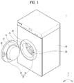
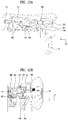
- FIG. 1 is a diagram showing a case that a home appliance including a locker is a washer.
- a locker of the present invention may be provided at various home appliances as well as to a washer, for clarity, the present invention shall be described with reference to a case that a home alliance including a locker is a washer.
- a washer corresponding to a home appliance includes a cabinet 10 forming an exterior, a storage space 12 provided within the cabinet 10, an entrance 14 provided at the cabinet 10 so as to communicate with the storage space 12, and a door 16 rotatably provided at the cabinet 10 so as to open/close the entrance 14.
- the laundry holding part 20 may include a tub configured to store wash water and a drum rotatably provided within the tub so as to store laundry.
- a hinge 18 for connecting the door 16 and the cabinet may be provided.
- the hinge 18 may be connected to one side of the door 16 and a front side of the cabinet 10 configuring a circumference of the entrance 14.
- FIG. 2 is a diagram showing a locker according to the present invention.
- a positive direction of an x-axis, a negative direction of the x-axis, a positive direction of a z-axis, a negative direction of the z-axis, a positive direction of a y-axis and a negative direction of the y-axis may be defined as a front direction, a rear direction, a top direction, a bottom direction, a right direction and a left direction, respectively.
- the x-, y- and z-axis orthogonal coordinates system rotates together according to an installed direction of the locker. In this case, definitions for a front/rear direction, a top/bottom direction, and a right/left direction may be changeable.
- a direction indicated by the rest of fingers is defined as a counterclockwise direction.
- a counterclockwise direction may be defined by the right handed screw rule with reference to a positive direction of the z-axis.
- a locker 30 may be provided.
- the locker 30 may include a latch 40 provided at one of the door 16 and the cabinet 10 and a coupling part 50 provided at the other.
- the latch 40 is provided at the door 16 in general, and the coupling part 50 is preferably provided at the cabinet 10.
- the coupling part 50 may include a latch insertion hole 132.
- the latch insertion hole 132 is provided at a front side of the cabinet 10. And, the latch 40 can enter or exit the latch insertion hole 132. By selectively fixing the latch 40, the door 16 can be fixed.
- the latch can be set not to be unfastened from the inside of the latch insertion hole, which is called the locking of the door.
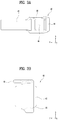
- FIG. 3 is a diagram showing a latch provided at the present invention.
- the latch 40 may include a latch bar 42 projected from the door 16, a latch head 44 provided at an end of the latch bar 42, a latch hole 46 provided at perforate the latch head 44, and a latch protrusion 48 protruding from the latch hole 46.
- the latch bar 42 may be provided in a manner that a top-bottom length is greater than a right-left width.
- the latch head 44 is provided at have a top-bottom length greater than the latch bar 42 and a right-left width smaller than the latch bar 42.
- the right-left width means a length in y-axis direction
- the top-bottom length means a length in z-axis direction.
- the latch hole 46 may be provided in the right-left width direction (e.g., y-axis direction) of the latch head 44, and a second insertion projection 234 (described later) is inserted in the latch hole 46. Details shall be described later.
- the latch protrusion 48 may be provided in a manner of extending from the latch head 44 of the top or bottom side of the latch hole 46 in a right direction (e.g., a positive direction of y-axis), and is preferably provided at the top side in the present invention.
- the top side means the positive direction of the z-axis and the bottom side means the negative direction of the z-axis.
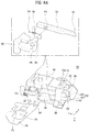
- FIG. 4 is a diagram showing a coupling part 50 provided at the present invention.
- the coupling part 50 may include a rear housing 110 shown in FIG. 4A and a front housing shown in FIG. 4B .
- the front and rear housings 130 and 110 are coupled together so as to form a housing 100. And, a prescribed space may be provided as an inner space 120 within the housing 100.
- the inner space 120 is formed in the front housing 130 and an open side of the rear is covered with the rear housing 110.
- the rear housing 110 may play a role as a cover configured to cover the open side of the front housing.
- the rear housing 110 may include a housing stopper 112 capable of restricting the movement of an operating part body 310 that will be described later.
- the housing stopper 112 may be provided in a manner of being projected from an inner surface of the rear housing 110.
- the housing stopper 112 may include at least one housing stopper recess 114 formed in a direction of the latch insertion hole 132 (i.e., a negative direction of y-axis).
- the front housing 130 may include the latch insertion hole 132 formed at the end of the front side.
- the coupling part 50 may be installed at the cabinet 10 so that the latch insertion hole 132 can be adjacent to the entrance 14. Namely, a gap between the entrance 14 and the latch insertion hole 132 is formed to be substantially equal to the thickness of a gasket 15 provided at the door 16, whereby a coupling force of the door by the locker 30 can be raised.
- the latch insertion hole 132 may include an insertion hole incline 132a formed by inclining in an insertion direction of the latch 40. If the latch 40 is inserted in a manner of being spaced apart in a prescribed distance from the latch insertion hole 132, the insertion hole incline 132a may guide the latch head 44 to the latch insertion hole 132 by coming in contact with the latch head 44.
- the latch insertion hole 132 may further include an insertion hole sill 132b formed in a manner of further inclining than the insertion hole incline 132a in the insertion direction of the latch 40.
- the insertion hole sill 132b may guide the latch protrusion 48 by coming in contact with the latch protrusion 48. Hence, when the latch 40 is inserted in the latch insertion hole 132, an insertion height of the latch 40 can beset uniform.
- the insertion hole sill 132b is preferably provided above the insertion hole incline 132a.
- the front housing 130 may include a first shaft guider hole 134 and a second shaft guider hole 136 configured to guide movements of a first shaft 316 and a second shaft 317 of the operating part 300 (described later) in a manner of having the shafts 316 and 317 inserted therein, respectively [cf. FIG. 2 ].
- the first shaft guider hole 134 and the second shaft guider hole 136 may be provided at the front side of the front housing 130 having the latch insertion hole 132 formed therein.
- the first shaft guider hole 134 may extend in a first length in a right-left direction. And, the first shaft 316 is guided in the right-left direction by the first shaft guider hole 134.
- the second shaft guider hole 136 may include a second shaft guider hole-1 136a extending in a first prescribed length in a right-left direction by being spaced apart from the first shat guider hole 134 and a second shaft guider hole-2 136b extending in a second prescribed length in a top-bottom direction (preferably upward) from an end of the second shaft guider hole-1 136a.
- an engaging part 200, an operating part 300, a slider 400, a door open/close sensing part 500 and an electric device 600 may be accommodated.
- An engaging part, an operating part, a slider and an error detecting part are described in order with reference to FIGs. 5 to 8 as follows.
- FIG. 5 is a diagram showing an engaging part provided at the present invention.
- the engaging part 200 is rotatably provided within the housing 100.
- the engaging part 200 may include an engaging part body 210, an engaging part rotation shaft 220 provided at the engaging part body 210, a latch insertion portion 230 extending from one end of the engaging part body 210 so as to receive a force by coming in contact with the latch 40, and a pressurizing portion 240 extending from the other end of the engaging part body 210.
- the engaging part rotation shaft 220 may extend in a top-bottom direction (i.e., z-axis direction) from a lateral side of the engaging part body 210, and both ends of the engaging part rotation shaft 220 may be rotatably coupled with the housing 100.
- an engaging part torsion spring 222 may be provided at the engaging part rotation shaft 220. Namely, the engaging part torsion spring 222 rotates the engaging part 200 in a direction for the latch insertion portion 230 to get closer to the latch insertion hole 132.
- the engaging part torsion spring 222 perforates the engaging part rotation shaft 220.
- One end of the engaging part torsion spring 222 is fixed to the engaging part body 210 and the other end is fixed to the housing 100.
- the engaging part torsion spring 222 With reference to the positive direction of z-axis, the engaging part torsion spring 222 provides an elastic force to the engaging part 200 in a counterclockwise direction. Such a direction is called a restoration rotation direction of the engaging part 200.
- the latch insertion portion 230 may extend to one end of the engaging part body 210 toward a side provided with the latch insertion hole 132.
- the latch insertion portion 230 may include a first insertion projection 232 extending from the engaging part body 210, a second insertion projection 234 extending from the engaging part body 210 so as to be spaced apart from the first insertion projection 232, and an insertion recess 236 provided between the first insertion projection 232 and the second insertion projection 234.
- the first insertion projection 232 may be provided at a place more distant from the latch insertion hole 132 than the second insertion projection 234.
- the first insertion projection 232 extends from one side of the engaging part body 210
- the second insertion projection 234 may extend from one side of the engaging part body 210 so as to be spaced apart from the first insertion projection 232.
- an extension length of the second insertion projection 234 may be smaller than that of the first insertion projection 232.
- the engaging part rotation shaft 220 may be provided in a manner of deviating from a center of the engaging part body 210.
- the first insertion projection 232 may extend from an end of the engaging part body 210 relatively close to the engaging part rotation shaft 220
- the second insertion projection 234 may extend from an end of the engaging part body 210 relatively distant from the engaging part rotation shaft 220.
- a portion of the engaging part body 210 from which the second insertion projection 234 extends may be located farther than a portion of the engaging part body 210 from which the first insertion projection 232 extends.
- the engaging part rotation shaft 220 may be placed on an extension line of the first insertion projection 232. And, the engaging part rotation shaft 220 may be provided not to be placed on an extension line of the second insertion projection 234.
- the pressurizing portion 240 may be formed in a manner of extending from the other end of the engaging part body 210, i.e., the engaging part body 210 located in a direction opposite to the latch insertion portion 230 centering on the engaging part rotation shaft 220.
- the pressurizing portion 240 can move the operating part 300 by pressurizing the operating part 300 in case that the engaging part 200 is rotated by the latch 40 in a direction opposite to the restoration rotation direction.
- a direction in which the pressurizing portion 240 pressurizes the operating part 300 shall be named a pressurizing direction.
- the pressurizing portion 240 may include a first pressurizing projection 242, a second pressurizing projection 244 and a third pressurizing projection 246.
- the first pressurizing projection 242, the second pressurizing projection 244 and the third pressurizing projection 246 may differ from each other in length.
- the first pressurizing projection 242 may be formed shorter than the second pressurizing projection 244
- the second pressurizing projection 244 may be formed shorter than the third pressurizing projection 246, and the first pressurizing projection 242 may be formed shorter than the third pressurizing projection 246.
- the first pressurizing projection 242, the second pressurizing projection 244 and the third pressurizing projection 246 include a first pressurizing point P1, a second pressurizing point P2 and a third pressurizing point P3, which pressurize the operating part 300, respectively.
- the first to third pressurizing points P1 to P3 may differ from each other in height. For instance, a height of the first pressurizing point P1 is smaller than that of the second or third pressurizing point P2 or P3, and a height of the third pressurizing point P3 may be smaller than that of the second pressurizing point P2. This is shown in FIG. 5A .
- the first to third pressurizing points P1 to P3 may be provided in a manner of differing from each other in the rotated angle with reference to the engaging part rotation shaft 220.
- the first pressurizing point P1 is provided at a location rotated counterclockwise further than the third or second pressurizing point P3 or P2 and the third pressurizing point P3 may be provided at a location rotated counterclockwise further than the second pressurizing point P2. This is shown in FIG. 5A as well.
- the first to third pressurizing points P1 to P3 may be provided in a manner of differing from each other in a straight distance from a center C1 of the engaging part rotation shaft 220.
- the lengths may gradually decrease in order of a radius of the third pressurizing point P3, a radius of the second pressurizing point P2 and a radius of the first pressurizing point P1. This is shown in FIG. 5A .
- the rotation radiuses of the first to third pressurizing points P1 to P3 may be provided so as not to overlap with each other.
- the first pressurizing projection 242 extends from the engaging part body 210 and may have the same width of the engaging part body 210.
- the width of the first pressurizing projection 242 means a length extending in the z-axis direction.
- An end of the first pressurizing projection 242 is rounded so as to move smoothly by coming in contact with a first incline surface 322 of a header (described later).
- the second pressurizing projection 244 may be provided at a location further spaced than the first pressurizing projection 242 in a restoration rotation direction.
- the restoration rotation direction is the direction indicated by the rest of four fingers.
- a width of the second pressurizing projection 244 may be set smaller than that of the first pressurizing projection 242.
- a first pressurizing recess 242a is provided between the first and second pressurizing projections 242 and 244.
- the first pressurizing recess 242a fixes the engaging part 200 as a header 320, which will be described later, is inserted in the recess 242a and restricts the engaging part 200 from rotating in the restoration rotation direction.
- the third pressurizing projection 246 may extend from the second pressurizing projection 244 in a direction opposite to the restoration rotation direction of the engaging part 200.
- a width of the third pressurizing projection 246 may be set smaller than that of the first pressurizing projection 242.
- the third pressurizing projection 246 may be provided on the axis of the engaging part rotation shaft 220 different from the first pressurizing projection 242.
- a third pressurizing surface 246a may be provided at an end of the third pressurizing projection 246.
- a normal line of the third pressurizing surface 246a is formed to incline toward the operating part 300. Namely, if the third pressurizing surface 246a pressurizes the operating part 300, a force is applied to the operating part 300 in a direction vertical to a pressurizing direction.
- the operating part 300 makes a rotational motion centering on a first shaft 316, which will be described in detail later.
- the engaging part 200 may further include a fourth pressurizing projection 250 extending from the engaging part body 210.
- the fourth pressurizing projection 250 extends from the engaging part body 210 and may be provided at be spaced apart from the first pressurizing projection 242 in a direction opposite to the restoration rotation direction. And, the fourth pressurizing projection 250 may be provided in a manner that a straight distance from a center C1 of the engaging part rotation shaft 220 is smaller than that of the first pressurizing projection 242.
- the fourth pressurizing projection 250 plays a role as a stopper of the slider 400 attempting to move in a direction of the latch insertion hole 132 by receiving an elastic force, which will be described in detail with the slider 400.
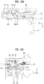
- FIG. 6 is a diagram showing an operating part provided at the present invention.
- the operating part 300 operates by receiving a force from the pressuring portion 240 of the engaging part 200.
- the operating part 300 is capable of a straight motion () of getting more distant from or closer to the latch insertion hole 132 (e.g., a case of closing a door, a case of forcing a door to be opened) and a rotational motion centering on the first shaft 316 (e.g., a general case of opening a door).
- a structure for implementing an operation of the operating part 300 is described as follows.
- the operating part 300 may include an operating part body 310, a header 320 provided at one end of the operating part body 310, a trigger 332, and a release bar 342.
- the first and second shafts 316 and 317 extending from the operating part body 310 may be provided at one surface of the operating part body 310.
- the first and second shafts 316 and 317 may be provided in a manner of by being projected from a bottom surface (with reference to the drawing of FIG. 6A ) of the operating part body 310 in the positive direction of z-axis and may be spaced apart from each other.
- the first and second shafts 316 and 317 are guided by being inserted in the aforementioned first and second shaft guider holes 134 and 136, respectively. And, they become the elements of restricting the movement of the operating part 300.
- an operating part body stopper 313 may be provided at one surface of the operating part body 310.
- the operating part body stopper 313 may be formed by being projected from a top surface (with reference to the drawing of FIG. 6A ) of the operating part body 310 in the negative direction of x-axis.
- the operating part body stopper 313 may include at least one operating part stopper recess 313a extending in a direction (y-axis direction) of getting distant from the latch insertion hole 132.
- the operating part stopper recess 313a and the housing stopper recess 114 are spaced apart from each other in a moving direction of the operating part 300.
- the operating part stopper recess 313a and the housing stopper recess 114 are inserted by crossing with each other. Hence, the housing stopper 112 and the operating part body stopper 313 do not restrict mutual motions.
- the header 320 may include a first header incline surface 322 and a second header incline surface 324. If the engaging part 200 rotates in a pressurizing direction, the first header incline surface 322 means a surface pressurized by the first pressurizing projection 242. If the engaging part 200 rotates in a restoration rotation direction, the second header incline surface 324 means a surface pressurized by the first pressurizing projection 242. With reference to the drawing of FIG. 6A , the first header incline surface 322 and the second header incline surface 324 meet the end of the header 320 and the first header incline surface 322 may be provided over the second header incline surface 324.
- the header 320 is rotatably connected to the operating part body 310 by the header shaft 328, and may be provided at the end of the operating part body 310 close to the latch insertion hole 132.
- the end of the header 320 may be provided in a manner of failing to further move above the header shaft 328 and rotating at a prescribed angle equal to or smaller than the header shaft 328. So to speak, the end of the header 320 is able to rotate up to the same height of the header shaft 328 only.
- a header sill 326 protruding from a surface vertical to the header shaft 328.
- the header sill 326 restricts rotation of the header 320, thereby preventing the end of the header 320 from moving to a location higher than the header shaft 328.
- the trigger 332 may be provided at be movable to the operating part body 310 in a direction getting more distant from or closer to the latch insertion hole 132 (i.e., y-axis direction). Namely, the trigger 332 may move in a straight movement direction of the operating part 300. And, the trigger 332 is preferably provided in form of a bar.
- the operating part body 310 may further include a trigger guider 330 configured to guide the trigger 332.
- the trigger guider 330 is provided at one surface of the operating part body 310, and the trigger 332 moves by perforating the trigger guider 330.
- the trigger 332 may include a trigger incline 334 provided at one end close to the latch insertion hole 132 by inclining downward with reference to a moving direction of the trigger 332.
- the trigger incline 334 may be provided in the same inclining direction of the first header incline surface 322.
- the trigger incline 334 may be pressurized by the second pressurizing projection 244. In this case, the trigger 332 may move in a direction getting distant from the latch insertion hole 132 (e.g., positive direction of y-axis) by being guided by the trigger guider 330.
- the operating part 300 may further include a rotation stopper 350 configured to rotate by communicating with the trigger 332.
- the rotation stopper 350 is rotatably connected to the operating part body 310. Since a rotation stopper fixing portion 356 is fixed to the operating part 310 through a rotation stopper perforated hole 358 provided at the rotation stopper 350, the rotation stopper 350 can rotate centering on the rotation stopper fixing portion 356.
- a rotation stopper interlocking projection 352 projected from the rotation stopper 350 may be inserted in a trigger communicating hole 336 provided at the trigger 332.
- the rotation stopper 350 can rotate. For instance, as shown in FIG. 6A , if the trigger 332 moves in a direction getting distant from the latch insertion hole 132 (i.e., positive direction of y-axis), a torque is generated from the rotation stopper 350 so as to rotate clockwise.
- the rotation stopper before rotation by the trigger 332 restricts the movement of the slider 400 that will be described later. If the rotation stopper 350 rotates by the trigger 332, it fails to restrict the movement of the slider 400 but the slider 400 may move in the direction of the latch insertion hole 132. Details shall be described later.
- the operating part 300 may further include a rotation stopper torsion spring 354 configured to provide an elastic force for restoring the rotation stopper 350 into an original state.
- the original state means a state before the rotation stopper 350 rotates in response to a movement of the trigger 332. Namely, if the trigger 332 rotates the rotation stopper 350 by moving in a direction getting distant from the latch insertion hole 132, it means that the rotation stopper 350 is rotated to enable the trigger 332 to move in the direction of the latch insertion hole 132.
- the rotation stopper torsion spring 354 is perforated by the fixing portion 356 of the rotation stopper, one end is fixed to the rotation stopper 350, and the other end may be fixed to the operating part body 310.
- the release bar 342 may be provided at the operating part body 310 to be movable in a direction getting distant from or close to the latch insertion hole 132 (i.e., y-axis direction). Namely, the release bar 342 may move in a straight movement direction of the operating part 300. Moreover, the release bar 342 is preferably provided as a bar type.
- the release bar 342 may be provided under the trigger 332 with reference to FIG. 6B . So to speak, the release bar 342 is preferably provided closer to a bottom side of the operating part body 310.
- the operating part body 310 may further include a release bar guider 340 configured to guide the movement of the release bar 342.
- the release bar guider 340 is provided at one surface of the operating part body 310 provided with the trigger guider 330. And, the release bar 342 may move by perforating the release bar guider 340.
- the release bar 342 may be configured so as to be provided an elastic restoration force in a direction getting distant from the latch insertion hole 132 (i.e., positive direction of y-axis). To this end, as shown in FIG. 6B , a release bar spring 346 may be provided between an end of the release bar 342 and the release bar guider 340.
- the release bar spring 346 is released by the release bar 342, one end of the release bar spring 346 is fixed to an end of the release bar 342 (e.g., an end portion of the release bar located at a side distant from the latch insertion hole 1321), the other end of the release bar spring 346 is fixed to the release bar guider 340.
- the release bar 342 moves in a direction of the latch insertion hole 132 (i.e., negative direction of y-axis)
- the release bar spring 346 is compressed to generate an elastic force.
- the elastic force may work as a restoring force for moving the release bar 342 in a positive direction of y-axis.
- the release bar 342 is moved by the release bar spring 346 in a direction getting distant from the latch insertion hole 132 (i.e., positive direction of y-axis). In doing so, the release bar stopper 344 may restrict the movement of the release bar 342.
- the release bar stopper 344 may be provided at an outer circumference of the release bar 342 so as to have a cross-sectional area wider than that of the release bar 342 perforating the release bar guider 340.
- the release bar stopper 344 may be fixed to the other end of the release bar 342 (e.g., an end portion of the release bar located closer to the latch insertion hole 132).
- the release bar stopper 344 is caught on the release bar guider 340 so as to restrict the movement of the release bar 342.
- the operating part 300 may further include a release portion incline 348 pressurized by the third pressurizing projection 246.
- the release portion incline 348 may be provided at the release bar 342, and more particularly, to the other end of the release bar 342 (i.e., an end portion of the release bar located closer to the latch insertion hole 132) or the release bar stopper 344.
- the release portion incline 348 is formed to inline on a lateral surface of the operating part 300, and the third pressurizing projection 246 may be provided in a normal direction of the release portion incline 348.
- a pressurized force may be divided into a vertical drag of pressurizing the release portion incline 348 vertically and a frictional force between the release portion incline and the third pressurizing projection 246. And, the vertical drag can be further divided into a vertical component (x-axis direction) force and a horizontal component (y-z plane) force.
- the force of the vertical component fails to contribute to the movement of the operating part body 310.
- the force of the horizontal component works on a lateral surface of the operating part body 310 so as to work as a turning force by which the operating part body 310 can be rotated centering on the first shaft 316.
- a rotation radius of the operating part body 310 is restricted by the second shaft 317 guided within the second shaft guider hole 136.
- the operating part body 310 receives a force in the z-axis direction and rotates counterclockwise with reference to the negative direction of the x-axis (i.e., direction in parallel with the first shaft).
- the operating part body 310 may be provided with an elastic force by the second spring 312 in a direction opposite to the rotation direction of the operating part body 310 rotated by the third pressurizing projection 246.
- the second spring 312 may be provided at an opposite of the operating part body 310 provided with the release portion incline 348.
- One end of the second spring 312 may be fixed to the second fixing projection 152 provided at the housing 100 and the other end of the second spring 312 may be fixed to the second spring operating part fixing projection 319.
- the operating part body 310 can be provided with an elastic force by the first spring 311 in the direction of the latch insertion hole 132 (or, negative direction of y-axis).
- the first spring 311 may be provided at the other end of the operating part body 310, i.e., an opposite side of a portion of the operating part body 310 provided with the header 320.
- the first spring is a compressed coil spring and can provide a force of pushing the operating part body 310 in the direction of the latch insertion hole 132.
- a first spring insertion hole 318 may be provide to the operating part body 310 so that one end of the first spring 311 can be inserted therein.
- the operating part body 310 may include a first fixing projection 150 projected from the housing 100 so as to fix the other end of the first spring 311 thereto.
- the operating part body 310 may further include a rotation delay guider recess configured to delay the restoration rotation of the operating part body 310.
- the rotation delay guider recess 360 is provided at a bottom side of the operating part body 310, and may be formed concave so as to have a prescribed length in a direction getting distant or close to the latch insertion hole 132.
- the rotation delay guider recess 360 may include a rotation delay rib 364 extending from a lateral surface of the operating part body 310 and a rotation delay doorway 362 communicating with the operating part body 310 by perforating the rotation delay rib 364 on a side distant from the latch insertion hole 132. And, the rotation delay rib 364 may be provided with a rotation delay incline 366 configured to incline downward toward an inside of the rotation delay guider recess 360 from an outside.
- the rotation delay incline 366 overstrides a top of the slider delay projection 460 and the slider delay projection 460 is inserted into the rotation delay guider recess 360.
- a movement of the rotation delay rib 364 is restricted by the slider delay projection 460.
- one of the slider 400 and the operating part body 310 makes a relative motion so that the slider delay projection 460 can be withdrawn externally through the rotation delay doorway 362.
- the slider delay projection 460 moves toward the rotation delay doorway 362 by moving into the rotation delay guider recess 360, the slider delay projection 460 is withdrawn externally through the rotation delay doorway 362. Thereafter, the operating part body 310 is rotated by the second spring 312 in an opposite direction (e.g., direction of returning to a state before rotating by being pressurized by the third pressurizing projection 246).
- the operating part 300 may include an operating part wing 370 extending from the operating part body 310.
- the operating part wing 370 is a plate member extending from a lateral surface of the operating part body 310 and may be perforated to form an operating part wing hole 374 therein.
- an operating part locking portion 372 may be further provided at one side of the operating part wing 370.
- the operating part wing hole 374 selectively communicates with a slider wing hole 452 (described later), thereby locking the closed door 16 not to be opened by a force of pushing or pulling the door.
- the operating part locking portion 372 means a portion on which a force of rotating the operating part body 310 works so that the operating part wing hole 374 and the slider wing hole 452 can communicate with each other.
- the operating part locking portion 372 may be provided with a concave recess or a convex projection.
- the operating part wing 370 extends from the operating part body 310 in a bottom direction (cf. FIG. 4B ) or a negative direction of z-axis, the operating part wing hole 374 is formed in a front-rear direction of an x-axis direction, the operating part locking portion 372 is provided at one side of the operating part wing 370, and the operating part body 310 may be provided at be rotated in the same direction of rotating the operating part body 310 by the third pressurizing projection 246. Namely, the operating part body 310 may be rotated in a counterclockwise direction with reference to the negative direction of x-axis.
- FIG. 7 is a diagram showing a slider provided at the present invention.
- the slider 400 may include a plate type member provided between the operating part 300 and the front housing 100.
- the slider 400 may include a slider perforated hole 470 perforated by the first and second shafts 316 and 317 extending from the operating part body 310. Hence, the movement of the operating part body 310 and the movement of the slider 400 may not interfere with each other.
- the slider 400 may be provided at receive an elastic force from the slider spring 410 in a direction of the latch insertion hole 132 within the housing 100.
- One end of the slider spring 410 may be fitted into a slider spring fixing projection 414 provided at an end of the slider 400 distant from the latch insertion hole 132, and the other end of the slider spring 410 may be fitted into a third fixing projection 412 projected from an inner circumference of the housing 100 opposing the end of the slider 400.
- the slider spring 410 if the slider 400 moves in a direction getting distant from the latch insertion hole 132, the slider spring 410 is compresses. And, an elastic force of the slider spring 410 works as a restoration force of moving the slider 400 in the direction of the latch insertion hole.
- the slider 400 may include a first slider stopper 420 projected from an end of the slider 400 adjacent to the latch insertion hole 132 in a direction vertical to a plate type of the slider 400 and a slider extension portion 440 projected in a horizontal direction.
- the first slider stopper 420 can move the slider 400 in the direction getting distant from the latch insertion hole 132 by being pressurized in a manner of coming in contact with the aforementioned fourth pressurizing projection 250.
- the fourth pressurizing projection 250 pressurizes one surface of the first slider stopper 420 (e.g., face close to the latch insertion hole 132) and the slider 400 moves in a direction getting distant from the latch insertion hole 132.
- the slider spring 410 provides an elastic force of moving the slider 400 in the direction of the latch insertion hole 132. Yet, since the elastic restoration force of the engaging part torsion spring 222 is stronger than that of the slider spring 410, the slider 400 moves in the direction getting distant from the latch insertion hole 132 (or, positive direction of y-axis).
- the slider 400 is moved by the elastic force of the slider spring 410 in the direction of the latch insertion hole 132.
- the slider extension portion 440 determines whether the door is closed in a manner of normally inserting the latch 40 in the latch insertion hole 132 and inserting the second insertion projection 234 in the latch hole 46.
- the slider extension portion 440 is exposed by being exposed up to a moving path of the latch 40 from the latch insertion hole 132. Yet, in the situation that the door 16 is normally closed, the latch is inserted in the latch insertion hole 132 and the latch protrusion 48 pressurizes the slider extension portion 440 so as to pushes it in a direction getting distant from the latch insertion hole.
- a location of the slider 400 in a state (normally closed door) that the latch 40 is normally inserted in the latch insertion hole 132 is provided closer to the latch insertion hole than that of the slider 400 in a state (open door) that the first slider stopper 420 is pressurized by the fourth pressurizing projection 250 or more distant than that of the slider 400 in a state (abnormally closed door) that the latch 40 is not normally inserted and that the first slider stopper 420 is not pressurized by the fourth pressurizing projection 250.
- the reason for this is to further perform a process for locking the door as well as for closing the door 16 in order to operate a home appliance.
- the door locking should be performed in the normal door closed state only but not be performed in the door open state or the abnormal door closed state. To this end, in the present invention, it is obtained whether the door currently corresponds to the normal door closed state, the door open state, or the abnormal door closed state according to a location of the slider wing hole 452 provided at the slider 400.
- the slider 400 may further include a second slider stopper 430 provided at an end of the slider 400 distant from the latch insertion hole 132 by being vertically protruding from the plate type member.
- the second slider stopper 430 is located in a direction opposite to the first slider stopper 420 centering on the slider perforated hole 470.
- a slider spring fixing projection 414 may be provided at the second slider stopper 430 by being projected in a direction getting distant from the latch insertion hole 132.
- the second slider stopper 430 may restrict a movement of the rotation stopper 350 in case that an external force is not applied to the rotation stopper 350 (e.g., a state that an elastic force by the rotation stopper torsion spring 354 is smallest, an original state that the rotation stopper 350 is not rotated by the trigger 332).
- an external force e.g., a state that an elastic force by the rotation stopper torsion spring 354 is smallest, an original state that the rotation stopper 350 is not rotated by the trigger 332.
- the slider 400 may move by receiving an elastic force in the direction of the latch insertion hole 132 from the slider spring 410, as the movement of the second slider stopper 430 is restricted by the rotation stopper 350, the movement of the slider 400 is restricted as well. This is valid for a case that the fourth pressurizing projection 250 does not pressurize the first slider stopper 420.
- the slider 400 may further include a slider delay projection 460 vertically projected from the plate type member.
- the slider delay projection 460 may be provided in a rotation radius of the rotation delay guider recess 360 provided at the bottom side of the operating part body 310. Meanwhile, the slider delay projection 460 led into the rotation delay guider recess 360 by overstriding the rotation delay inline 366. In doing so, the slider delay projection 460 may be damaged. To prevent it, as shown in FIG. 7 , a periphery of the slider delay projection 460 is cut but a prescribed side is connected, in order to give elasticity to the slider delay projection 460.
- the slider 400 may further include a slider wing 450 extending in one direction and a slider wing hole 452 provided at the slider wing.
- the slider wing 450 may be provided in a manner of extending in the same direction of the operating part wind 370.
- the slider wing hole 452 may be provided at have a cross-sectional area greater than the operating part wind hole 374.
- FIG. 8 is a diagram showing a door open/close sensing part provided at the present invention.
- a door open/close detecting part 500 may include a door detection interlocking portion 510 configured to be interlocked with the engaging part 200 and a door detection push portion 530 configured to be interlocked with an electric device 600 described later.
- the electric device 600 may mean a device capable of applying power to a home appliance or locking a closed door in response to opening/closing a door.
- the electronic device 600 may include a first detection projection 630 projected externally. If the first detection projection 620 is pushed, it may open an internal electric circuit so as not to supply power to a home appliance. If such a push is released, the projection 630 short-circuits the internal electric circuit so as to supply power to the home appliance. For another instance, while the first detection projection 630 is projected, as the electric circuit is open, power can be supplied. While the first detection projection 630 is pushed, the electric circuit may be short-circuited. Yet, for clarity of the description, the present invention shall describe a case of not supplying power if the first detection projection 630 is pushed.
- the door detection push portion 530 can control power not to be supplied to the home appliance by pushing the first detection projection 630. While the door is closed, the door detection push portion 530 can control power to be supplied to the home appliance by enabling the first detection projection 630 not to be pushed. Hence, it is able to prevent the home appliance from operating in a state that the door is not closed.
- the door open/close detecting part 500 may include a door detection interlocking portion 510 provided within the housing to be rotatable centering on the rotation shaft 520 by extending from the door detection rotation shaft 520 in a direction of the engaging part 200 and a door detection push portion 530 extending in a direction of the first detection projection 630.
- the door detection push portion 530 may include a push portion top surface 534 and a push portion incline surface 532 provided in a manner of inclining downward from the push portion top surface 534. While the door is open, the first detection projection 630 keeps being pushed by the push portion top surface 534. While the door is closed, as the door detection push portion 530 is moved so that the first detection projection 630 is moved along the push portion incline surface 532. Subsequently, if the first detection projection 630 passes a threshold point pushed by the push portion incline surface 532, it is fully projected from the electric device.
- the door detection interlocking portion 510 may include an interlocking recess 514 in which the engaging part interlocking projection 260 extending from the engaging part 200 is inserted. Hence, the interlocking recess 514 is moved by the engaging part interlocking projection 260 together in response to the rotation of the engaging part 200, and the door open/close detecting part 500 is rotated centering on the door detection rotation shaft 520.
- a door detection spring 540 configured to pressurize a rear side of the interlocking recess 514 may be provided.
- One end of the door detection spring 540 is fixed to the housing 100, and the other end may be fixed by being fitted into the door detection fixing projection 512 provided at the door detection interlocking portion 510.
- the electric device 600 may include a first locking projection 610 externally projected to be movable in top-bottom direction by an internal electric circuit and a second locking projection 620 configured to be selectively projected outward only if the first locking projection 610 is located at a specific position.
- the electric device 600 may further include a solenoid (not shown) inside. For instance, if current is supplied to the solenoid, the locking projection 610 moves downward.
- the first locking projection 610 may be inserted in the operating part locking portion 372. Hence, when the first locking projection 610 moves downward, the operating part locking portion 372 also receives a downward force, which can generate a rotation force of rotating the operating part wing 370 and the operating part body 310. Hence, the operating part body 310 can be rotated at a prescribed angle.
- the second locking projection 620 can be projected from the electric device 600. Namely, if the first locking projection 610 moves upward, the second locking projection 620 is led into an inside of the electric device 600. If the operating part wing hole 374 and the slider wing hole 452 communicate with each other at a right position (from which the second locking projection 620 is projected), the second locking projection 620 can be inserted by perforating the operating part wing hole 374 and the slider wing hole 452 both.
- the second locking projection 620 may be provided movable by the deformation of bimetal provided within the electric device 600.
- FIG. 9 is a diagram showing a state that a door is open in the present invention.
- FIG. 10 is a diagram showing a state that a door is closed in the present invention. An operation of closing an open door is described with reference to FIG. 9 and FIG. 10 in the following.
- an open door state means a state before inserting the latch 40 in the latch insertion hole 132.
- the engaging part 200 is provided with an elastic force by the engaging part torsion spring 222 in order for the first and second insertion projections 232 and 234 to rotate in a direction of the latch insertion hole 132.
- the slider 400 Since the fourth pressurizing projection 250 pressurizes the first slider stopper 420 in a direction getting distant from the latch insertion hole 132, the slider 400 is in a state of having moved in the direction getting distant from the latch insertion hole as well. Although the slider 400 receives the elastic force in the direction of the latch insertion hole 132 from the slider spring 410, since the elastic force of the slider spring 410 is smaller than that of the engaging part torsion spring 222, the slider spring 410 is in a maximally compressed state in a door open state.
- the operating part 300 is receiving the elastic force in the direction of the latch insertion hole 132 from the first spring 311, its motion is restricted by the first and second shafts 316 and 317 provided at the operating part 300.
- the latch 40 can be inserted in the latch insertion hole 132 at a uniform height.
- the latch head 44 pressurizes the first insertion projection 232 in a direction getting distant from the latch insertion hole 132 by coming in contact with the first insertion projection 232. If a force pressurized by the latch head 44 is greater than the elastic force of the engaging part torsion spring 222, the engaging part 200 is rotated in a direction opposite to an elastic force direction of the engaging part torsion spring 222.
- the second insertion projection 234 is inserted inside the latch hole 46, thereby fixing the latch 40 so as not to be withdrawn from the latch insertion hole 132.
- the first pressurizing projection 242 of the engaging part 200 pressurizes the header 320 of the operating part 300. Specifically, the first pressurizing projection 242 pressurizes the first header incline surface 322.
- the header 320 is provided at one end of the operating part body 310 so as to be rotatable in the direction of the latch insertion hole 132 only, the header 320 pressurized by the first pressurizing projection 242 rotates and the first pressurizing projection 242 continues to rotate along the first header incline surface 322.
- the operating part 300 moves in a direction getting distant from the latch insertion hole 132 and the engaging part torsion spring 222 is compressed.
- the engaging part 200 moves in an original state direction by receiving the elastic force of the engaging part torsion spring 222, since the header 320 is provided at restrict a rotational motion in the opposite direction of the latch insertion hole 132, if a position at which the header 320 cannot rotate is reached, the engaging part 200 is not rotated but fixed. Hence, the latch 40 is fixed by the second insertion projection 234 inserted in the latch hole 46.
- FIG. 11 shows a state before inserting the latch 40.
- the second slider stopper 430 receives an elastic force in a direction getting close to the latch insertion hole 132 (i.e., negative direction of y-axis) from the slider spring 410, it is in a state that a movement is restricted by the rotation stopper 350.
- FIG. 11 (b) shows a process for inserting the latch 40.
- the second pressurizing projection 244 pressurizes the trigger incline 334 and the trigger 322 moves in a direction getting distant from the latch insertion hole 132 (i.e., positive direction of y-axis). Owing to the movement of the trigger 332, the rotation stopper 350 rotates.
- the rotation stopper 350 which has been restricted the movement of the second slider stopper 430, rotates, the second slider stopper 430 is moved in the direction of the latch insertion hole 132 by an elastic force of the slider spring 410.
- the second slider stopper 430 moves the release bar 342 in a direction getting close to the latch insertion hole 132 (i.e., negative direction of y-axis) by applying a force to the end of the release bar 342. This is because the elastic force of the release bar spring 346 is provided smaller than that of the slider spring 410.
- the release bar incline 348 provided at the end of the release bar 342 enters a rotation radius R3 of the third pressurizing projection 246. As shown in FIG. 11 (a) , the release bar incline 348 does not enter the rotation radius R3 of the third pressurizing projection 246 until the latch 40 is inserted.
- the present invention it is able to set a time interval to enable the release bar 342 to move after completion of rotation of the engaging part 200.
- the third pressurizing projection 246 may be provided at arrive at a position, where the release portion incline 348 arrives by being moved by the second slider stopper 430, earlier.
- the release bar incline 348 is set not to be placed within the rotation radius of the third pressurizing projection 246 in the course of closing the door.
- the release bar incline 348 is provided between the third pressurizing projection 246 and the housing 100. Or, the release bar incline 348 is provided in the radius direction of the third pressurizing projection 246. Or, the release bar incline 348 is placed in a pressurizing direction of the third pressurizing projection 246.
- the second insertion projection 234 is inserted in the latch hole 46 so as to fix the latch 40 and the door closed state can be maintained.
- FIG. 9A there is a difference in a position of the slider 400.
- the slider 400 As shown in FIG. 9A , since the second slider stopper 430 is pressurized by the third pressurizing projection 246 in the door open state, the slider 400 is located most distant from the latch insertion hole 132.
- the slider extension portion 440 is pressurized by the latch protrusion 48 in the door closed state, although the slider 400 moves in the direction getting distant from the latch insertion hole 132, a position of the slider 400 is located closer to the latch insertion hole 132 in comparison with the door open state.
- FIG. 12 is a diagram showing that a door is normally opened in the present invention.
- FIG. 13 is a diagram showing that a door is forced to be opened in the present invention. An operation of normally opening a door and an operation of forcing a door to be opened are described in detail with reference to FIG. 12 and FIG. 13 as follows.
- the latch 40 moves in a direction of being inserted in the latch insertion hole 132 (i.e., -, negative direction of x-axis) and rotates the engaging part 200 in an opposite direction of an elastic force direction of the engaging part torsion spring 222 (i.e., counterclockwise with reference to negative direction of z-axis).
- the third pressurizing projection 246 provided relatively lower than the first or second pressurizing projection 242 or 244 pressurizes the release portion incline 348.
- the release portion incline 348 and the operating part body 310 make rotational motions.
- the movement of the operating part 300 is limited to a straight motion in a direction getting distant from or close to the latch insertion hole 132 within the housing by the first shaft 316 and the second shaft 317 and a rotational motion in a direction guided by the second shaft with reference to the first shaft as a reference point.
- the force of pressurizing the release portion incline 348 contributes to the rotational motion of the operating part 300 only.
- the header 320 deviates from the rotation radius of the first pressurizing projection 242. Namely, since the header 320 that used to press the first pressurizing projection 242 disappears, the header 320 rotates into an original state using the elastic force by the engaging part torsion spring 222 as a restoration force.
- FIG. 11 (c) shows a state that the release portion incline 348 and the operating part 300 are rotated by the third pressurizing projection 2465. Owing to the rotation of the operating part 300, the pressurizing force of the second pressurizing projection 244 that used to work on the trigger incline 334 is removed. This is because the trigger incline 334 escapes from the rotation radius of the second pressurizing projection 244 owing to the rotation of the operating part 300.
- the trigger 332 receives a restoration force from the rotation stopper torsion spring 354 provided at the rotation stopper 350 and moves to an original state.
- the engaging part 200 rotates to restore into an original state by the elastic force of the engaging part torsion spring 222.
- the fourth pressurizing projection 250 of the engaging part 200 re-pressurizes the first slider stopper 420 so as to move the slider 400 in a direction getting distant from the latch insertion hole 132.
- the operating part 300 rotates into an original state using the elastic force of the second spring 312 as a restoration force.
- a time interval is set between the movement of the slider 400 and the rotation for the operating part 300 to return to an original state. This is implemented in a manner that the slider delay projection 460 is located in the rotation radius of the rotation delay rib 364 in case that the operating part 300 is rotated by the third pressurizing projection 246.
- the slider delay projection 460 is led into an inside of the rotation delay guider recess 360 by a relative movement of the rotation delay rib 364.
- the rotation delay rib 364 is unable to rotate due to the slider delay projection 460.
- the slider delay projection 460 is withdrawn externally through the rotation delay doorway 362 provided at one end of the rotation delay guider recess 360 while moving within the rotation delay guider recess 360 (e.g., while the slider is moving by the fourth pressurizing projection 250). In doing so, the restoration rotation of the operating part 300 is restricted but the slider 400 can move only. Hence, after the movement of the slider 400 has been preceded, the restoration rotation of the operation part 300 is performed in a manner of leaving a prescribed time interval.
- the latch 40 moves in a direction of being withdrawn from the latch insertion hole 132 (i.e., positive direction of x-axis).
- the second insertion projection 234 Since the second insertion projection 234 is already inserted in the latch hole 46, the second insertion projection 234 moves in the direction of the latch insertion hole 132, thereby moving the engaging part 200 in the elastic force direction of the engaging part torsion spring 222.
- the second header incline surface 324 seated at the first pressurizing recess 242a is pressurized by the first pressurizing projection 242
- the operating part 300 makes a straight movement in a direction getting distant from the latch insertion hole 132. If the first pressurizing projection 242 passes the threshold point over the end of the header 320, the engaging part 200 is fully rotated into the door open state by the engaging part torsion spring 222. Hence, the second insertion projection 234 is withdrawn from the latch hole 46 and the latch 40 is fully withdrawn from the latch insertion hole 132 as well.
- FIG. 14 is a diagram showing a state that a closed door is locked in present invention. An operation of locking a closed door is described with reference to FIG. 14 .
- the first locking projection 610 projected from the electric device 600 is moved downward.
- the first locking projection 610 is interlocked with the operating part locking portion 372 provided at the operating part wing 370. If a recess is provided at the operating part locking portion 372, the first locking projection 610 can be inserted in the recess of the operating part locking portion 372. Hence, if the first locking projection 610 is moved downward, a force is delivered to the operating part locking portion 372 and the operating part wing 370 and the operating part 300 are rotated in a direction that the second shaft 317 is above the second shaft 316 with reference to the second shaft 316 (i.e., positive direction of z-axis) or a counterclockwise direction for a negative direction of x-axis centering on the first shaft.
- a rotation angle of the operating part 300 by the first locking projection 610 is set smaller than that of the operating part 300 by the third pressurizing projection 246.
- the header 320 deviates from the rotation radius of the first pressurizing projection 242.
- the header 320 is still placed in the rotation radius of the first pressurizing projection 242. Hence, the door is not released by moving the first locking projection 610 downward.
- the operating part body stopper 313 provided at the rotated operating part 300 is placed on a moving trajectory of the housing stopper 112 provided at the housing.
- the operating part 300 receives a force of moving in a direction getting distant from the latch insertion hole 132. Yet, the movement of the operating part 300 may be restricted due to the interference between the operating part body stopper 313 and the housing stopper 112. Hence, it is unable to force the door to be opened.
- the body stopper 313 and the housing stopper 112 may enable the door to be opened by appropriately changing rigidity, thickness and the like. Namely, if a force over a predetermined level works, the operating part body stopper 313 or the housing stopper 112 is broken so that the door can be opened.
- the housing stopper recess 114 and the operating part stopper recess 313a cross with each other so as not to engage with each other despite that the operating part 300 is moved.
- the slider wing hole 452 and the operating part wing hole 374 may communicate with each other in order for the second locking projection 620, which is projected from the electric device 600 owing to the rotation of the operating part 300, to be inserted therein.
- the second locking projection 620 having perforated both of the slider wing hole 452 and the operating part wing hole 374 prevents the movement of the operating part 300, thereby preventing the door from being opened.
- the position of the slider 400 is a position at which the door is normally closed and corresponds to a state that the fourth pressurizing projection 250 does not pressurizes the first slider stopper 420 and that the latch protrusion 48 is pressurizing the slider extension portion 440.
- the position of the operating part corresponds to a state that the header 320 is seated at the first pressurizing recess 242a and that the operating part 300 is rotated by the first locking projection 610.
- the second locking projection 620 is a bimetal and is projected from the electric device, its pressurizing force is not significant. Hence, the positions of the operating part and the slider are placed at the above-mentioned positions, thereby enabling the operating part wing hole 374 and the slider wing hole 452 to communicate with each other.
- the home appliance according to the present invention may be set to operate only if the second locking projection 620 is fitted into both of the operating part wing hole 374 and the slider wing hole 452. In this case, as the closed door is locked, it is able to secure that the door is not opened during the home appliance operation.
Abstract
Description
- This application claims the benefit of Korean Patent Application No.
10-2016-0076848, filed on June 20, 2016 - The present invention relates to a locker and home appliance including the same.
- A home appliance consists of a cabinet forming an exterior, a storage space provided within the cabinet, an entrance provided at the cabinet so as to communicate with the storage space, and a door provided rotatably to the cabinet so as to open/close the entrance.
- A general home appliance includes a locker to open/close the door. And, the locker includes a latch provided at one of the door and the cabinet and a coupling part provided at the other so as to be detachably coupled with the latch.
- As a handle is provided at a front side of the door of the related art locker having the above-mentioned configuration in order to open/close the door, a user can open/close the door by holding the handle. However, if both hands are not usable, it causes a problem in opening/closing the door.
- Accordingly, the present invention is directed to a locker and home appliance including the same that substantially obviate one or more problems due to limitations and disadvantages of the related art.
- One object of the present invention is to provide a home appliance having a structure of a handle removed from a door.
- Another object of the present invention is to provide a home appliance, of which door can be opened/closed by an act of pushing a front side of a door.
- Another object of the present invention is to provide a home appliance, of which door can be opened by being pulled.
- Another object of the present invention is to provide a home appliance, of which door can be opened by being pushed from an inside of a cabinet in a closed state of the door.
- Further object of the present invention is to provide a home appliance including a safety device configured to prevent a door from being opened in the course of an operation of the home appliance.
- Technical tasks obtainable from the present invention are non-limited by the above-mentioned technical tasks. And, other unmentioned technical tasks can be clearly understood from the following description by those having ordinary skill in the technical field to which the present invention pertains.
- Additional advantages, objects, and features of the invention will be set forth in part in the description which follows and in part will become apparent to those having ordinary skill in the art upon examination of the following or may be learned from practice of the invention. The objectives and other advantages of the invention may be realized and attained by the structure particularly pointed out in the written description and claims hereof as well as the appended drawings.
- To achieve these objects and other advantages and in accordance with the purpose of the invention, as embodied and broadly described herein, a home appliance according to one embodiment of the present invention may include a cabinet having a storage space formed inside and an entrance communicating with the storage space, a door rotatably coupled with the cabinet to open/close the entrance, a latch provided at one of the door and the cabinet, and a coupling part provided at the other one of the door and the cabinet, the coupling part including a housing including a latch insertion hole which the latch inserted therein, an engaging part including an engaging part body rotatably provided within the housing, a latch insertion portion having an end of the latch inserted therein by extending from one end of the engaging part body, and a pressurizing portion having a first pressurizing projection and a third pressurizing projection by extending the other end of the engaging part body, an engaging part torsion spring provided at the engaging part to provide an elastic force so as to enable the latch insertion portion to rotate in a direction getting close to the latch insertion hole, an operating part configured to move in a direction getting distant from the latch insertion hole by being pressurized by the first pressurizing projection and rotate in a direction vertical, i.e. orthogonal or perpendicular, to a direction pressurized by the third pressurizing projection, a first spring providing a restoration force to enable the operating part to be restored into a state before being pressurized by the first pressurizing projection, and a second spring providing a restoration force to enable the operating part to be restored into a state before being pressurized by the third pressurizing projection.
- Preferably, the first pressurizing projection may be located closer to the operating part than the third pressurizing projection.
- More preferably, the operating part may include an operating part body receiving a force from each of the first spring and the second spring and a header including a first header incline surface provided at an end of the operating part body by inclining downward from the operating part body and a second incline surface connected to an end of the first header incline surface by inclining upward from the operating part body.
- If the door is closed, the first pressurizing projection may move the operating part by pressurizing the first header incline surface. If the first pressurizing projection passes an end of the header, a movement of the pressurizing projection may be restricted by the second header incline surface.
- A release bar incline configured to be pressurized by the third pressurizing projection may be provided at a lateral surface of the operating part body.
- Particularly, n the release bar incline may be provided at incline at a prescribed angle against a direction pressurized by the third pressurizing projection and the third pressurizing projection may further include a third pressurizing surface configured to incline to correspond to the release bar incline.
- More preferably, if the door is opened, the third pressurizing projection may rotate the operating part by pressurizing the release bar incline so that the header deviates from a rotation radius of the first pressurizing projection.
- Preferably, a length of the third pressurizing projection may be longer than that of the first pressurizing projection.
- More preferably, the header may be provided at an end of the operating part to be rotatable centering on a header shaft and an end of the header may fail to rotate over a position higher than the header shaft.
- And, the home appliance may further include a release bar having the release bar incline provided thereto, the release bar provided at be moveable in a direction equal to a moving direction of the operating part if pressurized by the first pressurizing projection and a release bar guider provided at the operating part body to guide the release bar.
- In this case, the release bar may be moved in order for the release bar incline to deviate from a rotation radius of the third pressurizing projection in a state that the door is open. And, the release bar may be moved in order for the release bar incline to be placed within the rotation radius of the third pressurizing projection in a state that the door is closed.
- Accordingly, the present invention provides the following effects and/or features.
- First of all, the present invention provides a home appliance having a structure of a handle removed from a door.
- Secondly, the present invention provides a home appliance, of which door can be opened/closed by an act of pushing a front side of a door.
- Thirdly, the present invention provides a home appliance, of which door can be opened by being pulled.
- Fourthly, the present invention provides a home appliance, of which door can be opened by being pushed from an inside of a cabinet in a closed state of the door.
- Fifthly, the present invention provides a home appliance including a safety device configured to prevent a door from being opened in the course of an operation of the home appliance.
- Effects obtainable from the present invention may be non-limited by the above mentioned effect. And, other unmentioned effects can be clearly understood from the following description by those having ordinary skill in the technical field to which the present invention pertains.
- It is to be understood that both the foregoing general description and the following detailed description of the present invention are exemplary and explanatory and are intended to provide further explanation of the invention as claimed.
- The accompanying drawings, which are included to provide a further understanding of the invention and are incorporated in and constitute a part of this application, illustrate embodiment(s) of the invention and together with the description serve to explain the principle of the invention. In the drawings:
-
FIG. 1 is a diagram showing a case that a home appliance including a locker is a washer; -
FIG. 2 is a diagram showing a locker according to the present invention; -
FIG. 3 is a diagram showing a latch provided at the present invention; -
FIG. 4 is a diagram showing a coupling part provided at the present invention; -
FIG. 5 is a diagram showing an engaging part provided at the present invention; -
FIG. 6 is a diagram showing an operating part provided at the present invention; -
FIG. 7 is a diagram showing a slider provided at the present invention; -
FIG. 8 is a diagram showing a door open/close sensing part provided at the present invention; -
FIG. 9 is a diagram showing a state that a door is open in the present invention; -
FIG. 10 is a diagram showing a state that a door is closed in the present invention; -
FIG. 11 is a diagram showing the operational relation among a trigger, a rotation stopper and a release bar; -
FIG. 12 is a diagram showing that a door is normally opened in the present invention; -
FIG. 13 is a diagram showing that a door is forced to be opened in the present invention; and -
FIG. 14 is a diagram showing a state that a closed door is locked in present invention. - Reference will now be made in detail to the preferred embodiments of the present invention, examples of which are illustrated in the accompanying drawings. And, the present invention may be non-limited by the preferred embodiments of the present invention. Wherever possible, the same reference numbers will be used throughout the drawings to refer to the same or similar parts.
- Terminologies used in the present specification need to be construed based on the substantial meanings of the corresponding terminologies and the overall matters disclosed in the present specification rather than construed as simple names of the terminologies. If a term used in the present specification semantically conflicts with a general meaning of the corresponding term, it may follow the definition used in the present specification.
- The present invention relates to a
locker 30, which is configured to detachably fix adoor 15 to acabinet 10 having anentrance 14, and a home appliance. And,FIG. 1 is a diagram showing a case that a home appliance including a locker is a washer. - Although a locker of the present invention may be provided at various home appliances as well as to a washer, for clarity, the present invention shall be described with reference to a case that a home alliance including a locker is a washer.
- Referring to
FIG. 1 , a washer corresponding to a home appliance includes acabinet 10 forming an exterior, astorage space 12 provided within thecabinet 10, anentrance 14 provided at thecabinet 10 so as to communicate with thestorage space 12, and adoor 16 rotatably provided at thecabinet 10 so as to open/close theentrance 14. - And, a
laundry holding part 20 capable of holding laundry and the like may be provided within thestorage space 12. Thelaundry holding part 20 may include a tub configured to store wash water and a drum rotatably provided within the tub so as to store laundry. - And, a
hinge 18 for connecting thedoor 16 and the cabinet may be provided. Thehinge 18 may be connected to one side of thedoor 16 and a front side of thecabinet 10 configuring a circumference of theentrance 14. -
FIG. 2 is a diagram showing a locker according to the present invention. Referring to the orthogonal coordinates system shown inFIG. 2 , a positive direction of an x-axis, a negative direction of the x-axis, a positive direction of a z-axis, a negative direction of the z-axis, a positive direction of a y-axis and a negative direction of the y-axis may be defined as a front direction, a rear direction, a top direction, a bottom direction, a right direction and a left direction, respectively. Yet, the x-, y- and z-axis orthogonal coordinates system rotates together according to an installed direction of the locker. In this case, definitions for a front/rear direction, a top/bottom direction, and a right/left direction may be changeable. - Meanwhile, regarding a direction of rotation, with reference to a direction of a thumb of a right hand, a direction indicated by the rest of fingers is defined as a counterclockwise direction. For instance, a counterclockwise direction may be defined by the right handed screw rule with reference to a positive direction of the z-axis.
- In order to fix the
door 16, which is turned centering on thehinge 18, to thecabinet 10, alocker 30 may be provided. - Referring to
FIG. 2 , thelocker 30 may include alatch 40 provided at one of thedoor 16 and thecabinet 10 and acoupling part 50 provided at the other. Thelatch 40 is provided at thedoor 16 in general, and thecoupling part 50 is preferably provided at thecabinet 10. - The
coupling part 50 may include alatch insertion hole 132. Thelatch insertion hole 132 is provided at a front side of thecabinet 10. And, thelatch 40 can enter or exit thelatch insertion hole 132. By selectively fixing thelatch 40, thedoor 16 can be fixed. - Before describing the
latch 40 and thecoupling part 50 in further detail, an operation of the locker of the present invention is schematically described as follows. - First of all, in case of intending to close the open door, if a force is applied to the door in a cabinet direction, the latch is fixed in a manner of being inserted in the latch insertion hole.
- Secondly, in case of intending to open the closed door, if a force is applied to the door in the cabinet direction, the fixed latch is unfastened from the inside of the latch insertion hole so as to be pulled out of the latch insertion hole.
- Thirdly, in case of intending to force the closed door to be opened (e.g., if the door is pushed in a direction opposite to the cabinet direction or an inner side of the door is pushed from the inside of the cabinet), if the door is pulled with a predetermined force, the fixed latch is unfastened from the inside of the latch insertion hole so as to be pulled out of the latch insertion hole.
- Fourthly, if it is necessary to restrict the closed door from being opened, the latch can be set not to be unfastened from the inside of the latch insertion hole, which is called the locking of the door.
- In the following description, configurations of the
latch 40 and thecoupling part 50 and the operational relation between the latch and the coupling part according to the operation of the locker shall be described in order. -
FIG. 3 is a diagram showing a latch provided at the present invention. - Referring to
FIG. 3 , thelatch 40 may include alatch bar 42 projected from thedoor 16, alatch head 44 provided at an end of thelatch bar 42, alatch hole 46 provided at perforate thelatch head 44, and alatch protrusion 48 protruding from thelatch hole 46. - The
latch bar 42 may be provided in a manner that a top-bottom length is greater than a right-left width. Thelatch head 44 is provided at have a top-bottom length greater than thelatch bar 42 and a right-left width smaller than thelatch bar 42. Herein, the right-left width means a length in y-axis direction and the top-bottom length means a length in z-axis direction. If thelatch 40 is inserted in thelatch insertion hole 132, thelatch head 44 rotates theengaging part 200 by pressurizing afirst insertion projection 232 that will be described later. - The
latch hole 46 may be provided in the right-left width direction (e.g., y-axis direction) of thelatch head 44, and a second insertion projection 234 (described later) is inserted in thelatch hole 46. Details shall be described later. - The
latch protrusion 48 may be provided in a manner of extending from thelatch head 44 of the top or bottom side of thelatch hole 46 in a right direction (e.g., a positive direction of y-axis), and is preferably provided at the top side in the present invention. Herein, the top side means the positive direction of the z-axis and the bottom side means the negative direction of the z-axis. -
FIG. 4 is a diagram showing acoupling part 50 provided at the present invention. Thecoupling part 50 may include arear housing 110 shown inFIG. 4A and a front housing shown inFIG. 4B . - The front and
rear housings housing 100. And, a prescribed space may be provided as aninner space 120 within thehousing 100. - Preferably, according to the present invention, the
inner space 120 is formed in thefront housing 130 and an open side of the rear is covered with therear housing 110. Namely, therear housing 110 may play a role as a cover configured to cover the open side of the front housing. - The
rear housing 110 may include ahousing stopper 112 capable of restricting the movement of anoperating part body 310 that will be described later. Thehousing stopper 112 may be provided in a manner of being projected from an inner surface of therear housing 110. Thehousing stopper 112 may include at least onehousing stopper recess 114 formed in a direction of the latch insertion hole 132 (i.e., a negative direction of y-axis). - The
front housing 130 may include thelatch insertion hole 132 formed at the end of the front side. Herein, thecoupling part 50 may be installed at thecabinet 10 so that thelatch insertion hole 132 can be adjacent to theentrance 14. Namely, a gap between theentrance 14 and thelatch insertion hole 132 is formed to be substantially equal to the thickness of agasket 15 provided at thedoor 16, whereby a coupling force of the door by thelocker 30 can be raised. - The
latch insertion hole 132 may include aninsertion hole incline 132a formed by inclining in an insertion direction of thelatch 40. If thelatch 40 is inserted in a manner of being spaced apart in a prescribed distance from thelatch insertion hole 132, theinsertion hole incline 132a may guide thelatch head 44 to thelatch insertion hole 132 by coming in contact with thelatch head 44. - The
latch insertion hole 132 may further include aninsertion hole sill 132b formed in a manner of further inclining than theinsertion hole incline 132a in the insertion direction of thelatch 40. Theinsertion hole sill 132b may guide thelatch protrusion 48 by coming in contact with thelatch protrusion 48. Hence, when thelatch 40 is inserted in thelatch insertion hole 132, an insertion height of thelatch 40 can beset uniform. - Since the
latch protrusion 48 is provided above thelatch head 44, theinsertion hole sill 132b is preferably provided above theinsertion hole incline 132a. - Meanwhile, the
front housing 130 may include a firstshaft guider hole 134 and a secondshaft guider hole 136 configured to guide movements of afirst shaft 316 and asecond shaft 317 of the operating part 300 (described later) in a manner of having theshafts FIG. 2 ]. - The first
shaft guider hole 134 and the secondshaft guider hole 136 may be provided at the front side of thefront housing 130 having thelatch insertion hole 132 formed therein. - The first
shaft guider hole 134 may extend in a first length in a right-left direction. And, thefirst shaft 316 is guided in the right-left direction by the firstshaft guider hole 134. - Meanwhile, the second
shaft guider hole 136 may include a second shaft guider hole-1 136a extending in a first prescribed length in a right-left direction by being spaced apart from the firstshat guider hole 134 and a second shaft guider hole-2 136b extending in a second prescribed length in a top-bottom direction (preferably upward) from an end of the second shaft guider hole-1 136a. - Meanwhile, in the
inner space 120 formed within thehousing 100, anengaging part 200, an operatingpart 300, aslider 400, a door open/close sensing part 500 and anelectric device 600 may be accommodated. An engaging part, an operating part, a slider and an error detecting part are described in order with reference toFIGs. 5 to 8 as follows. -
FIG. 5 is a diagram showing an engaging part provided at the present invention. - Referring to
FIG. 4B andFIG. 5A , theengaging part 200 is rotatably provided within thehousing 100. - The
engaging part 200 may include anengaging part body 210, an engagingpart rotation shaft 220 provided at theengaging part body 210, alatch insertion portion 230 extending from one end of theengaging part body 210 so as to receive a force by coming in contact with thelatch 40, and a pressurizingportion 240 extending from the other end of theengaging part body 210. - The engaging
part rotation shaft 220 may extend in a top-bottom direction (i.e., z-axis direction) from a lateral side of theengaging part body 210, and both ends of the engagingpart rotation shaft 220 may be rotatably coupled with thehousing 100. - In order to rotate the
engaging part 200 counterclockwise with reference to the top direction (i.e., positive direction of z-axis), an engagingpart torsion spring 222 may be provided at the engagingpart rotation shaft 220. Namely, the engagingpart torsion spring 222 rotates theengaging part 200 in a direction for thelatch insertion portion 230 to get closer to thelatch insertion hole 132. - The engaging
part torsion spring 222 perforates the engagingpart rotation shaft 220. One end of the engagingpart torsion spring 222 is fixed to theengaging part body 210 and the other end is fixed to thehousing 100. With reference to the positive direction of z-axis, the engagingpart torsion spring 222 provides an elastic force to theengaging part 200 in a counterclockwise direction. Such a direction is called a restoration rotation direction of theengaging part 200. - Meanwhile, the
latch insertion portion 230 may extend to one end of theengaging part body 210 toward a side provided with thelatch insertion hole 132. Thelatch insertion portion 230 may include afirst insertion projection 232 extending from theengaging part body 210, asecond insertion projection 234 extending from theengaging part body 210 so as to be spaced apart from thefirst insertion projection 232, and aninsertion recess 236 provided between thefirst insertion projection 232 and thesecond insertion projection 234. - Herein, the
first insertion projection 232 may be provided at a place more distant from thelatch insertion hole 132 than thesecond insertion projection 234. Thefirst insertion projection 232 extends from one side of theengaging part body 210, and thesecond insertion projection 234 may extend from one side of theengaging part body 210 so as to be spaced apart from thefirst insertion projection 232. Moreover, an extension length of thesecond insertion projection 234 may be smaller than that of thefirst insertion projection 232. - The engaging
part rotation shaft 220 may be provided in a manner of deviating from a center of theengaging part body 210. In this case, thefirst insertion projection 232 may extend from an end of theengaging part body 210 relatively close to the engagingpart rotation shaft 220, and thesecond insertion projection 234 may extend from an end of theengaging part body 210 relatively distant from the engagingpart rotation shaft 220. Namely, centering on the engagingpart rotation shaft 220, a portion of theengaging part body 210 from which thesecond insertion projection 234 extends may be located farther than a portion of theengaging part body 210 from which thefirst insertion projection 232 extends. - The engaging
part rotation shaft 220 may be placed on an extension line of thefirst insertion projection 232. And, the engagingpart rotation shaft 220 may be provided not to be placed on an extension line of thesecond insertion projection 234. - Meanwhile, the pressurizing
portion 240 may be formed in a manner of extending from the other end of theengaging part body 210, i.e., theengaging part body 210 located in a direction opposite to thelatch insertion portion 230 centering on the engagingpart rotation shaft 220. - The pressurizing
portion 240 can move theoperating part 300 by pressurizing the operatingpart 300 in case that theengaging part 200 is rotated by thelatch 40 in a direction opposite to the restoration rotation direction. Hereinafter, in the present specification, a direction in which the pressurizingportion 240 pressurizes the operatingpart 300 shall be named a pressurizing direction. - The pressurizing
portion 240 may include afirst pressurizing projection 242, asecond pressurizing projection 244 and athird pressurizing projection 246. - The
first pressurizing projection 242, thesecond pressurizing projection 244 and thethird pressurizing projection 246 may differ from each other in length. For instance, thefirst pressurizing projection 242 may be formed shorter than thesecond pressurizing projection 244, thesecond pressurizing projection 244 may be formed shorter than thethird pressurizing projection 246, and thefirst pressurizing projection 242 may be formed shorter than thethird pressurizing projection 246. - The
first pressurizing projection 242, thesecond pressurizing projection 244 and thethird pressurizing projection 246 include a first pressurizing point P1, a second pressurizing point P2 and a third pressurizing point P3, which pressurize theoperating part 300, respectively. And, the first to third pressurizing points P1 to P3 may differ from each other in height. For instance, a height of the first pressurizing point P1 is smaller than that of the second or third pressurizing point P2 or P3, and a height of the third pressurizing point P3 may be smaller than that of the second pressurizing point P2. This is shown inFIG. 5A . - The first to third pressurizing points P1 to P3 may be provided in a manner of differing from each other in the rotated angle with reference to the engaging
part rotation shaft 220. For instance, with reference to the negative direction of z-axis on the engagingpart rotation shaft 220, the first pressurizing point P1 is provided at a location rotated counterclockwise further than the third or second pressurizing point P3 or P2 and the third pressurizing point P3 may be provided at a location rotated counterclockwise further than the second pressurizing point P2. This is shown inFIG. 5A as well. - Meanwhile, the first to third pressurizing points P1 to P3 may be provided in a manner of differing from each other in a straight distance from a center C1 of the engaging
part rotation shaft 220. For instance, the lengths may gradually decrease in order of a radius of the third pressurizing point P3, a radius of the second pressurizing point P2 and a radius of the first pressurizing point P1. This is shown inFIG. 5A . - Meanwhile, the rotation radiuses of the first to third pressurizing points P1 to P3 may be provided so as not to overlap with each other.
- Referring to
FIG. 5B , thefirst pressurizing projection 242 extends from theengaging part body 210 and may have the same width of theengaging part body 210. Herein, the width of thefirst pressurizing projection 242 means a length extending in the z-axis direction. An end of thefirst pressurizing projection 242 is rounded so as to move smoothly by coming in contact with afirst incline surface 322 of a header (described later). - The
second pressurizing projection 244 may be provided at a location further spaced than thefirst pressurizing projection 242 in a restoration rotation direction. In this case, when the right handed screw rule is used with reference to the positive direction of z-axis, as mentioned in the foregoing description, the restoration rotation direction is the direction indicated by the rest of four fingers. A width of thesecond pressurizing projection 244 may be set smaller than that of thefirst pressurizing projection 242. - A
first pressurizing recess 242a is provided between the first and second pressurizingprojections first pressurizing recess 242a fixes theengaging part 200 as aheader 320, which will be described later, is inserted in therecess 242a and restricts theengaging part 200 from rotating in the restoration rotation direction. - The
third pressurizing projection 246 may extend from thesecond pressurizing projection 244 in a direction opposite to the restoration rotation direction of theengaging part 200. A width of thethird pressurizing projection 246 may be set smaller than that of thefirst pressurizing projection 242. And, thethird pressurizing projection 246 may be provided on the axis of the engagingpart rotation shaft 220 different from thefirst pressurizing projection 242. - A
third pressurizing surface 246a may be provided at an end of thethird pressurizing projection 246. A normal line of thethird pressurizing surface 246a is formed to incline toward the operatingpart 300. Namely, if thethird pressurizing surface 246a pressurizes the operatingpart 300, a force is applied to theoperating part 300 in a direction vertical to a pressurizing direction. The operatingpart 300 makes a rotational motion centering on afirst shaft 316, which will be described in detail later. - Meanwhile, the
engaging part 200 may further include afourth pressurizing projection 250 extending from theengaging part body 210. - The
fourth pressurizing projection 250 extends from theengaging part body 210 and may be provided at be spaced apart from thefirst pressurizing projection 242 in a direction opposite to the restoration rotation direction. And, thefourth pressurizing projection 250 may be provided in a manner that a straight distance from a center C1 of the engagingpart rotation shaft 220 is smaller than that of thefirst pressurizing projection 242. - The
fourth pressurizing projection 250 plays a role as a stopper of theslider 400 attempting to move in a direction of thelatch insertion hole 132 by receiving an elastic force, which will be described in detail with theslider 400. -
FIG. 6 is a diagram showing an operating part provided at the present invention. The operatingpart 300 operates by receiving a force from the pressuringportion 240 of theengaging part 200. In this case, the operatingpart 300 is capable of a straight motion () of getting more distant from or closer to the latch insertion hole 132 (e.g., a case of closing a door, a case of forcing a door to be opened) and a rotational motion centering on the first shaft 316 (e.g., a general case of opening a door). A structure for implementing an operation of the operatingpart 300 is described as follows. - Referring to
FIG. 6A andFIG. 6B , the operatingpart 300 may include anoperating part body 310, aheader 320 provided at one end of the operatingpart body 310, atrigger 332, and arelease bar 342. - The first and
second shafts part body 310 may be provided at one surface of the operatingpart body 310. The first andsecond shafts FIG. 6A ) of the operatingpart body 310 in the positive direction of z-axis and may be spaced apart from each other. The first andsecond shafts part 300. - Meanwhile, an operating
part body stopper 313 may be provided at one surface of the operatingpart body 310. The operatingpart body stopper 313 may be formed by being projected from a top surface (with reference to the drawing ofFIG. 6A ) of the operatingpart body 310 in the negative direction of x-axis. - The operating
part body stopper 313 may include at least one operatingpart stopper recess 313a extending in a direction (y-axis direction) of getting distant from thelatch insertion hole 132. The operatingpart stopper recess 313a and thehousing stopper recess 114 are spaced apart from each other in a moving direction of the operatingpart 300. - In general cases, the operating
part stopper recess 313a and thehousing stopper recess 114 are inserted by crossing with each other. Hence, thehousing stopper 112 and the operatingpart body stopper 313 do not restrict mutual motions. - The
header 320 may include a firstheader incline surface 322 and a secondheader incline surface 324. If theengaging part 200 rotates in a pressurizing direction, the firstheader incline surface 322 means a surface pressurized by thefirst pressurizing projection 242. If theengaging part 200 rotates in a restoration rotation direction, the secondheader incline surface 324 means a surface pressurized by thefirst pressurizing projection 242. With reference to the drawing ofFIG. 6A , the firstheader incline surface 322 and the secondheader incline surface 324 meet the end of theheader 320 and the firstheader incline surface 322 may be provided over the secondheader incline surface 324. - The
header 320 is rotatably connected to theoperating part body 310 by theheader shaft 328, and may be provided at the end of the operatingpart body 310 close to thelatch insertion hole 132. - The end of the
header 320 may be provided in a manner of failing to further move above theheader shaft 328 and rotating at a prescribed angle equal to or smaller than theheader shaft 328. So to speak, the end of theheader 320 is able to rotate up to the same height of theheader shaft 328 only. - To this end, a
header sill 326 protruding from a surface vertical to theheader shaft 328. Theheader sill 326 restricts rotation of theheader 320, thereby preventing the end of theheader 320 from moving to a location higher than theheader shaft 328. - Meanwhile, referring to
FIG. 6A , thetrigger 332 may be provided at be movable to theoperating part body 310 in a direction getting more distant from or closer to the latch insertion hole 132 (i.e., y-axis direction). Namely, thetrigger 332 may move in a straight movement direction of the operatingpart 300. And, thetrigger 332 is preferably provided in form of a bar. - The operating
part body 310 may further include atrigger guider 330 configured to guide thetrigger 332. Thetrigger guider 330 is provided at one surface of the operatingpart body 310, and thetrigger 332 moves by perforating thetrigger guider 330. - The
trigger 332 may include atrigger incline 334 provided at one end close to thelatch insertion hole 132 by inclining downward with reference to a moving direction of thetrigger 332. Thetrigger incline 334 may be provided in the same inclining direction of the firstheader incline surface 322. Thetrigger incline 334 may be pressurized by thesecond pressurizing projection 244. In this case, thetrigger 332 may move in a direction getting distant from the latch insertion hole 132 (e.g., positive direction of y-axis) by being guided by thetrigger guider 330. - Meanwhile, the operating
part 300 may further include arotation stopper 350 configured to rotate by communicating with thetrigger 332. Therotation stopper 350 is rotatably connected to theoperating part body 310. Since a rotationstopper fixing portion 356 is fixed to theoperating part 310 through a rotation stopper perforatedhole 358 provided at therotation stopper 350, therotation stopper 350 can rotate centering on the rotationstopper fixing portion 356. - A rotation
stopper interlocking projection 352 projected from therotation stopper 350 may be inserted in atrigger communicating hole 336 provided at thetrigger 332. Hence, if thetrigger 332 moves in a y-axis direction, therotation stopper 350 can rotate. For instance, as shown inFIG. 6A , if thetrigger 332 moves in a direction getting distant from the latch insertion hole 132 (i.e., positive direction of y-axis), a torque is generated from therotation stopper 350 so as to rotate clockwise. - The rotation stopper before rotation by the
trigger 332 restricts the movement of theslider 400 that will be described later. If therotation stopper 350 rotates by thetrigger 332, it fails to restrict the movement of theslider 400 but theslider 400 may move in the direction of thelatch insertion hole 132. Details shall be described later. - Meanwhile, the operating
part 300 may further include a rotationstopper torsion spring 354 configured to provide an elastic force for restoring therotation stopper 350 into an original state. Herein, the original state means a state before therotation stopper 350 rotates in response to a movement of thetrigger 332. Namely, if thetrigger 332 rotates therotation stopper 350 by moving in a direction getting distant from thelatch insertion hole 132, it means that therotation stopper 350 is rotated to enable thetrigger 332 to move in the direction of thelatch insertion hole 132. - The rotation
stopper torsion spring 354 is perforated by the fixingportion 356 of the rotation stopper, one end is fixed to therotation stopper 350, and the other end may be fixed to theoperating part body 310. - Meanwhile, referring to
FIG. 6B , therelease bar 342 may be provided at the operatingpart body 310 to be movable in a direction getting distant from or close to the latch insertion hole 132 (i.e., y-axis direction). Namely, therelease bar 342 may move in a straight movement direction of the operatingpart 300. Moreover, therelease bar 342 is preferably provided as a bar type. - The
release bar 342 may be provided under thetrigger 332 with reference toFIG. 6B . So to speak, therelease bar 342 is preferably provided closer to a bottom side of the operatingpart body 310. - The operating
part body 310 may further include arelease bar guider 340 configured to guide the movement of therelease bar 342. Therelease bar guider 340 is provided at one surface of the operatingpart body 310 provided with thetrigger guider 330. And, therelease bar 342 may move by perforating therelease bar guider 340. - The
release bar 342 may be configured so as to be provided an elastic restoration force in a direction getting distant from the latch insertion hole 132 (i.e., positive direction of y-axis). To this end, as shown inFIG. 6B , arelease bar spring 346 may be provided between an end of therelease bar 342 and therelease bar guider 340. - The
release bar spring 346 is released by therelease bar 342, one end of therelease bar spring 346 is fixed to an end of the release bar 342 (e.g., an end portion of the release bar located at a side distant from the latch insertion hole 1321), the other end of therelease bar spring 346 is fixed to therelease bar guider 340. Hence, if therelease bar 342 moves in a direction of the latch insertion hole 132 (i.e., negative direction of y-axis), therelease bar spring 346 is compressed to generate an elastic force. The elastic force may work as a restoring force for moving therelease bar 342 in a positive direction of y-axis. - The
release bar 342 is moved by therelease bar spring 346 in a direction getting distant from the latch insertion hole 132 (i.e., positive direction of y-axis). In doing so, therelease bar stopper 344 may restrict the movement of therelease bar 342. Therelease bar stopper 344 may be provided at an outer circumference of therelease bar 342 so as to have a cross-sectional area wider than that of therelease bar 342 perforating therelease bar guider 340. Therelease bar stopper 344 may be fixed to the other end of the release bar 342 (e.g., an end portion of the release bar located closer to the latch insertion hole 132). - Hence, if the
release bar 342 is moved by therelease bar spring 346 in a direction of getting distant from thelatch insertion hole 132, therelease bar stopper 344 is caught on therelease bar guider 340 so as to restrict the movement of therelease bar 342. - Meanwhile, the operating
part 300 may further include arelease portion incline 348 pressurized by thethird pressurizing projection 246. Therelease portion incline 348 may be provided at therelease bar 342, and more particularly, to the other end of the release bar 342 (i.e., an end portion of the release bar located closer to the latch insertion hole 132) or therelease bar stopper 344. - The
release portion incline 348 is formed to inline on a lateral surface of the operatingpart 300, and thethird pressurizing projection 246 may be provided in a normal direction of therelease portion incline 348. - When the
third pressurizing projection 246 pressurizes the release portion incline 348 (positive direction of x-axis), a pressurized force may be divided into a vertical drag of pressurizing therelease portion incline 348 vertically and a frictional force between the release portion incline and thethird pressurizing projection 246. And, the vertical drag can be further divided into a vertical component (x-axis direction) force and a horizontal component (y-z plane) force. - Since the operating
part body 310 is provided within thehousing 100 so as not to be moveable in an x-axis direction, the force of the vertical component fails to contribute to the movement of the operatingpart body 310. On the contrary, the force of the horizontal component works on a lateral surface of the operatingpart body 310 so as to work as a turning force by which theoperating part body 310 can be rotated centering on thefirst shaft 316. In this case, a rotation radius of the operatingpart body 310 is restricted by thesecond shaft 317 guided within the secondshaft guider hole 136. - In the present invention, if the
release portion incline 348 is pressurized by thethird pressurizing projection 246, the operatingpart body 310 receives a force in the z-axis direction and rotates counterclockwise with reference to the negative direction of the x-axis (i.e., direction in parallel with the first shaft). - Meanwhile, the operating
part body 310 may be provided with an elastic force by thesecond spring 312 in a direction opposite to the rotation direction of the operatingpart body 310 rotated by thethird pressurizing projection 246. As shown inFIG. 4B , thesecond spring 312 may be provided at an opposite of the operatingpart body 310 provided with therelease portion incline 348. One end of thesecond spring 312 may be fixed to thesecond fixing projection 152 provided at thehousing 100 and the other end of thesecond spring 312 may be fixed to the second spring operatingpart fixing projection 319. Hence, if the operatingpart body 310 is rotated by the pressing force of thethird pressurizing projection 246, thesecond spring 312 is compressed. If the pressing force of thethird pressurizing projection 246 disappears, the compressedsecond spring 312 provides a restoration force for rotationally moving the operatingpart body 310 into an original sate. - Referring to
FIG. 4B andFIG. 6A , the operatingpart body 310 can be provided with an elastic force by thefirst spring 311 in the direction of the latch insertion hole 132 (or, negative direction of y-axis). Thefirst spring 311 may be provided at the other end of the operatingpart body 310, i.e., an opposite side of a portion of the operatingpart body 310 provided with theheader 320. The first spring is a compressed coil spring and can provide a force of pushing the operatingpart body 310 in the direction of thelatch insertion hole 132. - Referring to
FIG. 6C andFIG. 4B , a firstspring insertion hole 318 may be provide to theoperating part body 310 so that one end of thefirst spring 311 can be inserted therein. And, the operatingpart body 310 may include afirst fixing projection 150 projected from thehousing 100 so as to fix the other end of thefirst spring 311 thereto. - Referring to
FIG. 6D , in order to prevent theoperating part body 310 from being immediately restored by thesecond spring 312 after theoperating part body 310 has been rotated by thethird pressurizing projection 246, the operatingpart body 310 may further include a rotation delay guider recess configured to delay the restoration rotation of the operatingpart body 310. - The rotation
delay guider recess 360 is provided at a bottom side of the operatingpart body 310, and may be formed concave so as to have a prescribed length in a direction getting distant or close to thelatch insertion hole 132. - The rotation
delay guider recess 360 may include arotation delay rib 364 extending from a lateral surface of the operatingpart body 310 and arotation delay doorway 362 communicating with the operatingpart body 310 by perforating therotation delay rib 364 on a side distant from thelatch insertion hole 132. And, therotation delay rib 364 may be provided with arotation delay incline 366 configured to incline downward toward an inside of the rotationdelay guider recess 360 from an outside. - If the operating
part body 310 is rotated by the pressurization of thethird pressurizing projection 246, as a slider delay projection 460 (described later) is provided in a rotation radius of therotation delay incline 366, therotation delay incline 366 overstrides a top of theslider delay projection 460 and theslider delay projection 460 is inserted into the rotationdelay guider recess 360. Hence, although the operatingpart body 310 attempts to rotate in an opposite direction, a movement of therotation delay rib 364 is restricted by theslider delay projection 460. - In order for the
slider delay projection 460 to be withdrawn from the rotationdelay guider recess 360, one of theslider 400 and the operatingpart body 310 makes a relative motion so that theslider delay projection 460 can be withdrawn externally through therotation delay doorway 362. - In the present invention, as the
slider delay projection 460 moves toward therotation delay doorway 362 by moving into the rotationdelay guider recess 360, theslider delay projection 460 is withdrawn externally through therotation delay doorway 362. Thereafter, the operatingpart body 310 is rotated by thesecond spring 312 in an opposite direction (e.g., direction of returning to a state before rotating by being pressurized by the third pressurizing projection 246). - Referring now to
FIG. 6A , the operatingpart 300 may include anoperating part wing 370 extending from the operatingpart body 310. The operatingpart wing 370 is a plate member extending from a lateral surface of the operatingpart body 310 and may be perforated to form an operatingpart wing hole 374 therein. And, an operatingpart locking portion 372 may be further provided at one side of the operatingpart wing 370. - The operating
part wing hole 374 selectively communicates with a slider wing hole 452 (described later), thereby locking theclosed door 16 not to be opened by a force of pushing or pulling the door. And, the operatingpart locking portion 372 means a portion on which a force of rotating the operatingpart body 310 works so that the operatingpart wing hole 374 and the slider wing hole 452 can communicate with each other. - The operating
part locking portion 372 may be provided with a concave recess or a convex projection. - In the present invention, the operating
part wing 370 extends from the operatingpart body 310 in a bottom direction (cf.FIG. 4B ) or a negative direction of z-axis, the operatingpart wing hole 374 is formed in a front-rear direction of an x-axis direction, the operatingpart locking portion 372 is provided at one side of the operatingpart wing 370, and the operatingpart body 310 may be provided at be rotated in the same direction of rotating the operatingpart body 310 by thethird pressurizing projection 246. Namely, the operatingpart body 310 may be rotated in a counterclockwise direction with reference to the negative direction of x-axis. -
FIG. 7 is a diagram showing a slider provided at the present invention. Referring toFIG. 4B andFIG. 7 , theslider 400 may include a plate type member provided between the operatingpart 300 and thefront housing 100. - The
slider 400 may include a sliderperforated hole 470 perforated by the first andsecond shafts part body 310. Hence, the movement of the operatingpart body 310 and the movement of theslider 400 may not interfere with each other. - As shown in
FIG. 4B , theslider 400 may be provided at receive an elastic force from theslider spring 410 in a direction of thelatch insertion hole 132 within thehousing 100. - One end of the
slider spring 410 may be fitted into a sliderspring fixing projection 414 provided at an end of theslider 400 distant from thelatch insertion hole 132, and the other end of theslider spring 410 may be fitted into athird fixing projection 412 projected from an inner circumference of thehousing 100 opposing the end of theslider 400. - Hence, if the
slider 400 moves in a direction getting distant from thelatch insertion hole 132, theslider spring 410 is compresses. And, an elastic force of theslider spring 410 works as a restoration force of moving theslider 400 in the direction of the latch insertion hole. - Referring to
FIG. 7 , theslider 400 may include afirst slider stopper 420 projected from an end of theslider 400 adjacent to thelatch insertion hole 132 in a direction vertical to a plate type of theslider 400 and aslider extension portion 440 projected in a horizontal direction. - The
first slider stopper 420 can move theslider 400 in the direction getting distant from thelatch insertion hole 132 by being pressurized in a manner of coming in contact with the aforementionedfourth pressurizing projection 250. - So to speak, if the
latch insertion portion 230 is rotated in the direction of thelatch insertion hole 132 by an elastic force of the engagingpart torsion spring 222, thefourth pressurizing projection 250 pressurizes one surface of the first slider stopper 420 (e.g., face close to the latch insertion hole 132) and theslider 400 moves in a direction getting distant from thelatch insertion hole 132. - In this case, the
slider spring 410 provides an elastic force of moving theslider 400 in the direction of thelatch insertion hole 132. Yet, since the elastic restoration force of the engagingpart torsion spring 222 is stronger than that of theslider spring 410, theslider 400 moves in the direction getting distant from the latch insertion hole 132 (or, positive direction of y-axis). - Yet, if the
engaging part 200 is rotated by inserting thelatch 40, since thefourth pressurizing projection 250 is unable to further pressurize thefirst slider stopper 420, theslider 400 is moved by the elastic force of theslider spring 410 in the direction of thelatch insertion hole 132. - In a situation that the
first slider stopper 420 is not pressurized by thefourth pressurizing projection 250, i.e., a situation that the engaging part is not rotated despite that the elastic restoration force by the engagingpart torsion spring 222 is working owing to theheader 320 coupled with thefirst pressurizing recess 242a by the rotated engagingpart 200, theslider extension portion 440 determines whether the door is closed in a manner of normally inserting thelatch 40 in thelatch insertion hole 132 and inserting thesecond insertion projection 234 in thelatch hole 46. - In detail, in the situation that the
first slider stopper 420 is not pressurized by thefourth pressurizing projection 250, theslider extension portion 440 is exposed by being exposed up to a moving path of thelatch 40 from thelatch insertion hole 132. Yet, in the situation that thedoor 16 is normally closed, the latch is inserted in thelatch insertion hole 132 and thelatch protrusion 48 pressurizes theslider extension portion 440 so as to pushes it in a direction getting distant from the latch insertion hole. - A location of the
slider 400 in a state (normally closed door) that thelatch 40 is normally inserted in thelatch insertion hole 132 is provided closer to the latch insertion hole than that of theslider 400 in a state (open door) that thefirst slider stopper 420 is pressurized by thefourth pressurizing projection 250 or more distant than that of theslider 400 in a state (abnormally closed door) that thelatch 40 is not normally inserted and that thefirst slider stopper 420 is not pressurized by thefourth pressurizing projection 250. - This becomes the factor for determining a location of the slider wing hole 452 (described later) provided at the
slider 400. The reason for this is to further perform a process for locking the door as well as for closing thedoor 16 in order to operate a home appliance. - The door locking should be performed in the normal door closed state only but not be performed in the door open state or the abnormal door closed state. To this end, in the present invention, it is obtained whether the door currently corresponds to the normal door closed state, the door open state, or the abnormal door closed state according to a location of the slider wing hole 452 provided at the
slider 400. - Meanwhile, the
slider 400 may further include asecond slider stopper 430 provided at an end of theslider 400 distant from thelatch insertion hole 132 by being vertically protruding from the plate type member. Namely, thesecond slider stopper 430 is located in a direction opposite to thefirst slider stopper 420 centering on the slider perforatedhole 470. - And, a slider
spring fixing projection 414 may be provided at thesecond slider stopper 430 by being projected in a direction getting distant from thelatch insertion hole 132. - The
second slider stopper 430 may restrict a movement of therotation stopper 350 in case that an external force is not applied to the rotation stopper 350 (e.g., a state that an elastic force by the rotationstopper torsion spring 354 is smallest, an original state that therotation stopper 350 is not rotated by the trigger 332). In other words, although theslider 400 may move by receiving an elastic force in the direction of thelatch insertion hole 132 from theslider spring 410, as the movement of thesecond slider stopper 430 is restricted by therotation stopper 350, the movement of theslider 400 is restricted as well. This is valid for a case that thefourth pressurizing projection 250 does not pressurize thefirst slider stopper 420. - Meanwhile, the
slider 400 may further include aslider delay projection 460 vertically projected from the plate type member. Theslider delay projection 460 may be provided in a rotation radius of the rotationdelay guider recess 360 provided at the bottom side of the operatingpart body 310. Meanwhile, theslider delay projection 460 led into the rotationdelay guider recess 360 by overstriding the rotation delay inline 366. In doing so, theslider delay projection 460 may be damaged. To prevent it, as shown inFIG. 7 , a periphery of theslider delay projection 460 is cut but a prescribed side is connected, in order to give elasticity to theslider delay projection 460. - The
slider 400 may further include aslider wing 450 extending in one direction and a slider wing hole 452 provided at the slider wing. Theslider wing 450 may be provided in a manner of extending in the same direction of the operatingpart wind 370. And, the slider wing hole 452 may be provided at have a cross-sectional area greater than the operatingpart wind hole 374. -
FIG. 8 is a diagram showing a door open/close sensing part provided at the present invention. Referring toFIG. 8 , a door open/close detecting part 500 may include a doordetection interlocking portion 510 configured to be interlocked with theengaging part 200 and a doordetection push portion 530 configured to be interlocked with anelectric device 600 described later. - The
electric device 600 may mean a device capable of applying power to a home appliance or locking a closed door in response to opening/closing a door. - As shown in
FIG. 4A , theelectronic device 600 may include afirst detection projection 630 projected externally. If thefirst detection projection 620 is pushed, it may open an internal electric circuit so as not to supply power to a home appliance. If such a push is released, theprojection 630 short-circuits the internal electric circuit so as to supply power to the home appliance. For another instance, while thefirst detection projection 630 is projected, as the electric circuit is open, power can be supplied. While thefirst detection projection 630 is pushed, the electric circuit may be short-circuited. Yet, for clarity of the description, the present invention shall describe a case of not supplying power if thefirst detection projection 630 is pushed. - While the door is open, the door
detection push portion 530 can control power not to be supplied to the home appliance by pushing thefirst detection projection 630. While the door is closed, the doordetection push portion 530 can control power to be supplied to the home appliance by enabling thefirst detection projection 630 not to be pushed. Hence, it is able to prevent the home appliance from operating in a state that the door is not closed. - The door open/
close detecting part 500 may include a doordetection interlocking portion 510 provided within the housing to be rotatable centering on therotation shaft 520 by extending from the doordetection rotation shaft 520 in a direction of theengaging part 200 and a doordetection push portion 530 extending in a direction of thefirst detection projection 630. - The door
detection push portion 530 may include a pushportion top surface 534 and a pushportion incline surface 532 provided in a manner of inclining downward from the pushportion top surface 534. While the door is open, thefirst detection projection 630 keeps being pushed by the pushportion top surface 534. While the door is closed, as the doordetection push portion 530 is moved so that thefirst detection projection 630 is moved along the pushportion incline surface 532. Subsequently, if thefirst detection projection 630 passes a threshold point pushed by the pushportion incline surface 532, it is fully projected from the electric device. - The door
detection interlocking portion 510 may include an interlockingrecess 514 in which the engagingpart interlocking projection 260 extending from theengaging part 200 is inserted. Hence, the interlockingrecess 514 is moved by the engagingpart interlocking projection 260 together in response to the rotation of theengaging part 200, and the door open/close detecting part 500 is rotated centering on the doordetection rotation shaft 520. - In order to prevent the engaging
part interlocking projection 260 from escaping from the interlockingrecess 514, adoor detection spring 540 configured to pressurize a rear side of the interlockingrecess 514 may be provided. One end of thedoor detection spring 540 is fixed to thehousing 100, and the other end may be fixed by being fitted into the doordetection fixing projection 512 provided at the doordetection interlocking portion 510. - Meanwhile, as shown in
FIG. 4A , theelectric device 600 may include afirst locking projection 610 externally projected to be movable in top-bottom direction by an internal electric circuit and asecond locking projection 620 configured to be selectively projected outward only if thefirst locking projection 610 is located at a specific position. - In order to move the
first locking projection 610, theelectric device 600 may further include a solenoid (not shown) inside. For instance, if current is supplied to the solenoid, the lockingprojection 610 moves downward. - If the operating
part locking portion 372 provided at the operatingpart wing 370 is provided as a recess, thefirst locking projection 610 may be inserted in the operatingpart locking portion 372. Hence, when thefirst locking projection 610 moves downward, the operatingpart locking portion 372 also receives a downward force, which can generate a rotation force of rotating the operatingpart wing 370 and the operatingpart body 310. Hence, the operatingpart body 310 can be rotated at a prescribed angle. - Only if the
first locking projection 610 moves downward, thesecond locking projection 620 can be projected from theelectric device 600. Namely, if thefirst locking projection 610 moves upward, thesecond locking projection 620 is led into an inside of theelectric device 600. If the operatingpart wing hole 374 and the slider wing hole 452 communicate with each other at a right position (from which thesecond locking projection 620 is projected), thesecond locking projection 620 can be inserted by perforating the operatingpart wing hole 374 and the slider wing hole 452 both. - For instance, the
second locking projection 620 may be provided movable by the deformation of bimetal provided within theelectric device 600. - An operation of a locker according to the present invention is described in detail with reference to
FIGs. 9 to 13 as follows. -
FIG. 9 is a diagram showing a state that a door is open in the present invention.FIG. 10 is a diagram showing a state that a door is closed in the present invention. An operation of closing an open door is described with reference toFIG. 9 andFIG. 10 in the following. - Referring to
FIG. 9A and FIG. 9B , an open door state means a state before inserting thelatch 40 in thelatch insertion hole 132. Theengaging part 200 is provided with an elastic force by the engagingpart torsion spring 222 in order for the first andsecond insertion projections latch insertion hole 132. - Since the
fourth pressurizing projection 250 pressurizes thefirst slider stopper 420 in a direction getting distant from thelatch insertion hole 132, theslider 400 is in a state of having moved in the direction getting distant from the latch insertion hole as well. Although theslider 400 receives the elastic force in the direction of thelatch insertion hole 132 from theslider spring 410, since the elastic force of theslider spring 410 is smaller than that of the engagingpart torsion spring 222, theslider spring 410 is in a maximally compressed state in a door open state. - Meanwhile, although the
operating part 300 is receiving the elastic force in the direction of thelatch insertion hole 132 from thefirst spring 311, its motion is restricted by the first andsecond shafts part 300. - Referring to
FIG. 9C , if thelatch head 44 is inserted in thelatch insertion hole 132, since thelatch protrusion 48 is guided by theinsertion hole sill 132b provided at thelatch insertion hole 132, thelatch 40 can be inserted in thelatch insertion hole 132 at a uniform height. - The
latch head 44 pressurizes thefirst insertion projection 232 in a direction getting distant from thelatch insertion hole 132 by coming in contact with thefirst insertion projection 232. If a force pressurized by thelatch head 44 is greater than the elastic force of the engagingpart torsion spring 222, theengaging part 200 is rotated in a direction opposite to an elastic force direction of the engagingpart torsion spring 222. - If the
latch 40 is fully inserted in thelatch insertion hole 132, thesecond insertion projection 234 is inserted inside thelatch hole 46, thereby fixing thelatch 40 so as not to be withdrawn from thelatch insertion hole 132. - The
first pressurizing projection 242 of theengaging part 200 pressurizes theheader 320 of the operatingpart 300. Specifically, thefirst pressurizing projection 242 pressurizes the firstheader incline surface 322. - Since the
header 320 is provided at one end of the operatingpart body 310 so as to be rotatable in the direction of thelatch insertion hole 132 only, theheader 320 pressurized by thefirst pressurizing projection 242 rotates and thefirst pressurizing projection 242 continues to rotate along the firstheader incline surface 322. - In this case, the operating
part 300 moves in a direction getting distant from thelatch insertion hole 132 and the engagingpart torsion spring 222 is compressed. - Referring to
FIG. 10A , if thefirst pressurizing projection 242 goes over an end of theheader 320, a force of pressurizing theheader 320 and theoperating part 300 disappears. Hence, the operatingpart 300 and theheader 320 is moved in the direction of thelatch insertion hole 132 by an elastic restoration force of the engagingpart torsion spring 222 and the end of theheader 320 is seated on thefirst pressurizing recess 242a of theengaging part 200. - Although the
engaging part 200 moves in an original state direction by receiving the elastic force of the engagingpart torsion spring 222, since theheader 320 is provided at restrict a rotational motion in the opposite direction of thelatch insertion hole 132, if a position at which theheader 320 cannot rotate is reached, theengaging part 200 is not rotated but fixed. Hence, thelatch 40 is fixed by thesecond insertion projection 234 inserted in thelatch hole 46. - The operational relation among a trigger, a rotation stopper and a release bar is described with reference to
FIG. 11 as follows. -
FIG. 11 shows a state before inserting thelatch 40. Although thesecond slider stopper 430 receives an elastic force in a direction getting close to the latch insertion hole 132 (i.e., negative direction of y-axis) from theslider spring 410, it is in a state that a movement is restricted by therotation stopper 350. -
FIG. 11 (b) shows a process for inserting thelatch 40. Before thefirst pressurizing projection 242 completely goes over an end of theheader 320, thesecond pressurizing projection 244 pressurizes thetrigger incline 334 and thetrigger 322 moves in a direction getting distant from the latch insertion hole 132 (i.e., positive direction of y-axis). Owing to the movement of thetrigger 332, therotation stopper 350 rotates. - Thus, as the
rotation stopper 350, which has been restricted the movement of thesecond slider stopper 430, rotates, thesecond slider stopper 430 is moved in the direction of thelatch insertion hole 132 by an elastic force of theslider spring 410. - As described above, the
second slider stopper 430 moves therelease bar 342 in a direction getting close to the latch insertion hole 132 (i.e., negative direction of y-axis) by applying a force to the end of therelease bar 342. This is because the elastic force of therelease bar spring 346 is provided smaller than that of theslider spring 410. - Thus, the
release bar incline 348 provided at the end of therelease bar 342 enters a rotation radius R3 of thethird pressurizing projection 246. As shown inFIG. 11 (a) , therelease bar incline 348 does not enter the rotation radius R3 of thethird pressurizing projection 246 until thelatch 40 is inserted. - This is because, if the
third pressurizing projection 246 and therelease bar incline 348 interfere with each other in the course of closing the door, since the operatingpart 300 is rotated, it may cause a problem that the door is not closed. - To prevent this, in the present invention, it is able to set a time interval to enable the
release bar 342 to move after completion of rotation of theengaging part 200. Or, thethird pressurizing projection 246 may be provided at arrive at a position, where therelease portion incline 348 arrives by being moved by thesecond slider stopper 430, earlier. Hence, therelease bar incline 348 is set not to be placed within the rotation radius of thethird pressurizing projection 246 in the course of closing the door. - Meanwhile, if a state that the door is closed is entered, as shown in
FIG. 10B and FIG. 10C , therelease bar incline 348 is provided between thethird pressurizing projection 246 and thehousing 100. Or, therelease bar incline 348 is provided in the radius direction of thethird pressurizing projection 246. Or, therelease bar incline 348 is placed in a pressurizing direction of thethird pressurizing projection 246. - If the door is closed, the
second insertion projection 234 is inserted in thelatch hole 46 so as to fix thelatch 40 and the door closed state can be maintained. - Meanwhile, comparing
FIG. 9A andFIG. 10C , there is a difference in a position of theslider 400. As shown inFIG. 9A , since thesecond slider stopper 430 is pressurized by thethird pressurizing projection 246 in the door open state, theslider 400 is located most distant from thelatch insertion hole 132. On the contrary, as shown inFIG. 10C , since theslider extension portion 440 is pressurized by thelatch protrusion 48 in the door closed state, although theslider 400 moves in the direction getting distant from thelatch insertion hole 132, a position of theslider 400 is located closer to thelatch insertion hole 132 in comparison with the door open state. -
FIG. 12 is a diagram showing that a door is normally opened in the present invention.FIG. 13 is a diagram showing that a door is forced to be opened in the present invention. An operation of normally opening a door and an operation of forcing a door to be opened are described in detail with reference toFIG. 12 andFIG. 13 as follows. - Referring to
FIG. 12A , if a front side of thedoor 16 is pushed to open the door, thelatch 40 moves in a direction of being inserted in the latch insertion hole 132 (i.e., -, negative direction of x-axis) and rotates theengaging part 200 in an opposite direction of an elastic force direction of the engaging part torsion spring 222 (i.e., counterclockwise with reference to negative direction of z-axis). - The
third pressurizing projection 246 provided relatively lower than the first orsecond pressurizing projection release portion incline 348. By the force of pressurizing therelease portion incline 348, as shown inFIG. 12B , therelease portion incline 348 and the operatingpart body 310 make rotational motions. - The reason for this is described as follows. First of all, the movement of the operating
part 300 is limited to a straight motion in a direction getting distant from or close to thelatch insertion hole 132 within the housing by thefirst shaft 316 and thesecond shaft 317 and a rotational motion in a direction guided by the second shaft with reference to the first shaft as a reference point. And, the force of pressurizing therelease portion incline 348 contributes to the rotational motion of the operatingpart 300 only. - Owing to the rotation of the operating
part 300, theheader 320 deviates from the rotation radius of thefirst pressurizing projection 242. Namely, since theheader 320 that used to press thefirst pressurizing projection 242 disappears, theheader 320 rotates into an original state using the elastic force by the engagingpart torsion spring 222 as a restoration force. -
FIG. 11 (c) shows a state that therelease portion incline 348 and theoperating part 300 are rotated by the third pressurizing projection 2465. Owing to the rotation of the operatingpart 300, the pressurizing force of thesecond pressurizing projection 244 that used to work on thetrigger incline 334 is removed. This is because thetrigger incline 334 escapes from the rotation radius of thesecond pressurizing projection 244 owing to the rotation of the operatingpart 300. - Thus, the
trigger 332 receives a restoration force from the rotationstopper torsion spring 354 provided at therotation stopper 350 and moves to an original state. - As the
latch 40 is withdrawn from thelatch insertion hole 132, theengaging part 200 rotates to restore into an original state by the elastic force of the engagingpart torsion spring 222. Thus, thefourth pressurizing projection 250 of theengaging part 200 re-pressurizes thefirst slider stopper 420 so as to move theslider 400 in a direction getting distant from thelatch insertion hole 132. In this case, the operatingpart 300 rotates into an original state using the elastic force of thesecond spring 312 as a restoration force. - In the present invention, a time interval is set between the movement of the
slider 400 and the rotation for theoperating part 300 to return to an original state. This is implemented in a manner that theslider delay projection 460 is located in the rotation radius of therotation delay rib 364 in case that the operatingpart 300 is rotated by thethird pressurizing projection 246. - Particularly, the
slider delay projection 460 is led into an inside of the rotationdelay guider recess 360 by a relative movement of therotation delay rib 364. In this case, although the operating part attempts to rotate for restoration by thesecond spring 312, therotation delay rib 364 is unable to rotate due to theslider delay projection 460. - The
slider delay projection 460 is withdrawn externally through therotation delay doorway 362 provided at one end of the rotationdelay guider recess 360 while moving within the rotation delay guider recess 360 (e.g., while the slider is moving by the fourth pressurizing projection 250). In doing so, the restoration rotation of the operatingpart 300 is restricted but theslider 400 can move only. Hence, after the movement of theslider 400 has been preceded, the restoration rotation of theoperation part 300 is performed in a manner of leaving a prescribed time interval. - Referring to
FIG. 13 , if the door is forced to be pulled, thelatch 40 moves in a direction of being withdrawn from the latch insertion hole 132 (i.e., positive direction of x-axis). - Since the
second insertion projection 234 is already inserted in thelatch hole 46, thesecond insertion projection 234 moves in the direction of thelatch insertion hole 132, thereby moving theengaging part 200 in the elastic force direction of the engagingpart torsion spring 222. - Although the second
header incline surface 324 seated at thefirst pressurizing recess 242a is pressurized by thefirst pressurizing projection 242, since the rotation of theheader 320 is restricted, the operatingpart 300 makes a straight movement in a direction getting distant from thelatch insertion hole 132. If thefirst pressurizing projection 242 passes the threshold point over the end of theheader 320, theengaging part 200 is fully rotated into the door open state by the engagingpart torsion spring 222. Hence, thesecond insertion projection 234 is withdrawn from thelatch hole 46 and thelatch 40 is fully withdrawn from thelatch insertion hole 132 as well. -
FIG. 14 is a diagram showing a state that a closed door is locked in present invention. An operation of locking a closed door is described with reference toFIG. 14 . - Referring to
FIG. 14A , when a home appliance is operating or if it is determined that it is necessary to lock a closed door, thefirst locking projection 610 projected from theelectric device 600 is moved downward. - The
first locking projection 610 is interlocked with the operatingpart locking portion 372 provided at the operatingpart wing 370. If a recess is provided at the operatingpart locking portion 372, thefirst locking projection 610 can be inserted in the recess of the operatingpart locking portion 372. Hence, if thefirst locking projection 610 is moved downward, a force is delivered to the operatingpart locking portion 372 and the operatingpart wing 370 and theoperating part 300 are rotated in a direction that thesecond shaft 317 is above thesecond shaft 316 with reference to the second shaft 316 (i.e., positive direction of z-axis) or a counterclockwise direction for a negative direction of x-axis centering on the first shaft. - Yet, a rotation angle of the operating
part 300 by thefirst locking projection 610 is set smaller than that of the operatingpart 300 by thethird pressurizing projection 246. Particularly, if the operating part is rotated by thethird pressurizing projection 246, theheader 320 deviates from the rotation radius of thefirst pressurizing projection 242. Yet, if the operatingpart 300 is rotated by thefirst locking projection 610, theheader 320 is still placed in the rotation radius of thefirst pressurizing projection 242. Hence, the door is not released by moving thefirst locking projection 610 downward. - As shown in
FIG. 14B , if the operatingpart 300 is rotated by thefirst locking projection 610, the operatingpart body stopper 313 provided at the rotated operatingpart 300 is placed on a moving trajectory of thehousing stopper 112 provided at the housing. - Hence, if the door is pulled to force to be opened (a case that the latch is pulled in a direction of being withdrawn from the latch insertion hole), the operating
part 300 receives a force of moving in a direction getting distant from thelatch insertion hole 132. Yet, the movement of the operatingpart 300 may be restricted due to the interference between the operatingpart body stopper 313 and thehousing stopper 112. Hence, it is unable to force the door to be opened. - Yet, if case of forcing the door to be opened, the
body stopper 313 and thehousing stopper 112 may enable the door to be opened by appropriately changing rigidity, thickness and the like. Namely, if a force over a predetermined level works, the operatingpart body stopper 313 or thehousing stopper 112 is broken so that the door can be opened. - Meanwhile, before the operating
part 300 is rotated by thefirst locking projection 610, thehousing stopper recess 114 and the operatingpart stopper recess 313a cross with each other so as not to engage with each other despite that the operatingpart 300 is moved. - Meanwhile, the slider wing hole 452 and the operating
part wing hole 374 may communicate with each other in order for thesecond locking projection 620, which is projected from theelectric device 600 owing to the rotation of the operatingpart 300, to be inserted therein. - The
second locking projection 620 having perforated both of the slider wing hole 452 and the operatingpart wing hole 374 prevents the movement of the operatingpart 300, thereby preventing the door from being opened. - In order for the projected second locking
projection 620 to perforate both of the slider wing hole 452 and the operatingpart wing hole 374, positions of the operating part and the slider are important. The position of theslider 400 is a position at which the door is normally closed and corresponds to a state that thefourth pressurizing projection 250 does not pressurizes thefirst slider stopper 420 and that thelatch protrusion 48 is pressurizing theslider extension portion 440. And, the position of the operating part corresponds to a state that theheader 320 is seated at thefirst pressurizing recess 242a and that the operatingpart 300 is rotated by thefirst locking projection 610. - Since the
second locking projection 620 is a bimetal and is projected from the electric device, its pressurizing force is not significant. Hence, the positions of the operating part and the slider are placed at the above-mentioned positions, thereby enabling the operatingpart wing hole 374 and the slider wing hole 452 to communicate with each other. - Meanwhile, the home appliance according to the present invention may be set to operate only if the
second locking projection 620 is fitted into both of the operatingpart wing hole 374 and the slider wing hole 452. In this case, as the closed door is locked, it is able to secure that the door is not opened during the home appliance operation. - It will be apparent to those skilled in the art that various modifications and variations can be made in the present invention without departing from the scope of the inventions. Thus, it is intended that the present invention covers the modifications and variations of this invention provided they come within the scope of the appended claims and their equivalents.
Claims (14)
- A home appliance, comprising:a cabinet (10) having a storage space (12) formed inside and an entrance (14) communicating with the storage space (12);a door (16) rotatably coupled with the cabinet (10) to open/close the entrance (12);a latch (40) provided at one of the door (16) and the cabinet (10); anda coupling part (50) provided at the other one of the door (16) and the cabinet (10), the coupling part comprising:a housing (100) including a latch insertion hole (132) for inserting the latch (40) therein;an engaging part (200), the engaging part (200) including an engaging part body (210) rotatably provided within the housing (210), a latch insertion portion (230) for insertion of an end of the latch (40), and a pressurizing portion (240) having a first pressurizing projection (242) and a third pressurizing projection (246), the latch insertion portion (230) and the pressurizing portion (240) being arranged at opposite ends of the engaging part body (210);an engaging part torsion spring (222) provided at the engaging part (200) and configured to provide an elastic force for enabling the latch insertion portion (230) to rotate in a direction getting close to the latch insertion hole (132);an operating part (300) configured to move in a direction getting distant from the latch insertion hole (132) when being pressurized by the first pressurizing projection (242) and to rotate in a direction vertical to a pressurizing direction of the third pressurizing projection (246);a first spring (311) for providing a restoration force to enable the operating part (300) to be restored into a state before being pressurized by the first pressurizing projection (242); anda second spring (312) for providing a restoration force to enable the operating part (300) to be restored into a state before being pressurized by the third pressurizing projection (246).
- The home appliance of claim 1, wherein the first pressurizing projection (242) is located closer to the operating part (300) than the third pressurizing projection (246).
- The home appliance of claim 1 or 2, the operating part (300) comprising an operating part body (310) for receiving a force from each of the first spring (311) and the second spring (312).
- The home appliance of claim 3, the operating part (300) comprising further a header (320) including a first header incline surface (322) and a second incline surface (324) provided at an end of the operating part body (310), the first header incline surface (322) and the second incline surface (324) being inclined with respect to each other and forming a pointed end of the operating part body (310).
- The home appliance of claim 4, wherein if the door (16) is closed, the first pressurizing projection (242) is configured to move the operating part (300) by pressurizing the first header incline surface (322).
- The home appliance of claim 4 or 5, wherein if the first pressurizing projection (242) passes an end of the header (320), a movement of the first pressurizing projection (242) is restricted by the second header incline surface (324).
- The home appliance according to any one of claims 3 to 6, wherein a release bar incline (348) configured to be pressurized by the third pressurizing projection (246) is provided at a lateral surface of the operating part body (310).
- The home appliance of claim 7, wherein the release bar incline (348) is inclined at a prescribed angle against a pressurizing direction of the third pressurizing projection (246).
- The home appliance of claim 8, wherein the third pressurizing projection (246) further includes a third pressurizing surface (246a) inclined corresponding to the release bar incline (348).
- The home appliance according to any one of claims 7 to 9, wherein if the door (16) is opened, the third pressurizing projection (246) is configured to rotate the operating part (300) by pressurizing the release bar incline (348) for removing the header (320) from a rotation radius of the first pressurizing projection (242).
- The home appliance of any one of claims 4 to 10, wherein the header (320) is provided at an end of the operating part (300) to be rotatable on a header shaft (328) and wherein a header sill (326) protruding from a surface vertical to the header shaft (328) is configured to prevent an end of the header (320) to rotate over a position higher than the header shaft (328).
- The home appliance according to any one of claims 5 to 11, further comprising:a release bar (342) having the release bar incline (348) provided thereto, the release bar (342) being moveable in a moving direction of the operating part (300) if pressurized by the first pressurizing projection (242); anda release bar guider (340) provided at the operating part body (310) to guide the release bar.
- The home appliance of claim 12, wherein the release bar (342) is configured to be moved for removing the release bar incline (348) from a rotation radius of the third pressurizing projection (246) in a state that the door (16) is open, and
wherein the release bar is configured to be moved for placing the release bar incline (348) within the rotation radius of the third pressurizing projection (246) in a state that the door (16) is closed. - The home appliance of any one of the preceding claims, wherein a length of the third pressurizing projection (246) is longer than that of the first pressurizing projection (242).
Applications Claiming Priority (1)
| Application Number | Priority Date | Filing Date | Title |
|---|---|---|---|
| KR1020160076848A KR102459278B1 (en) | 2016-06-20 | 2016-06-20 | Locker and Home Appliance comprising the same |
Publications (2)
| Publication Number | Publication Date |
|---|---|
| EP3260637A1 true EP3260637A1 (en) | 2017-12-27 |
| EP3260637B1 EP3260637B1 (en) | 2018-12-12 |
Family
ID=59034525
Family Applications (1)
| Application Number | Title | Priority Date | Filing Date |
|---|---|---|---|
| EP17175044.1A Active EP3260637B1 (en) | 2016-06-20 | 2017-06-08 | Locker and home appliance including the same |
Country Status (4)
| Country | Link |
|---|---|
| US (1) | US10920362B2 (en) |
| EP (1) | EP3260637B1 (en) |
| KR (1) | KR102459278B1 (en) |
| CN (1) | CN107524353B (en) |
Families Citing this family (7)
| Publication number | Priority date | Publication date | Assignee | Title |
|---|---|---|---|---|
| KR102411061B1 (en) * | 2015-11-23 | 2022-06-22 | 주식회사 에스 씨디 | Door lock device for washing machine |
| DE102016008317B4 (en) * | 2016-07-07 | 2018-10-31 | Emz-Hanauer Gmbh & Co. Kgaa | Door lock for a household electrical appliance |
| JP2020039694A (en) * | 2018-09-12 | 2020-03-19 | 東芝ライフスタイル株式会社 | Clothing treatment device |
| JP7389118B2 (en) * | 2018-11-29 | 2023-11-29 | イリノイ トゥール ワークス インコーポレイティド | Door locks and electronic devices |
| DE102019201718A1 (en) * | 2019-02-11 | 2020-08-13 | BSH Hausgeräte GmbH | Laundry treatment device |
| CN112981866A (en) * | 2019-12-18 | 2021-06-18 | 青岛海尔滚筒洗衣机有限公司 | Door lock assembly for clothes treatment equipment and clothes treatment equipment |
| DE102020124399B3 (en) * | 2020-08-31 | 2021-10-21 | Emz-Hanauer Gmbh & Co. Kgaa | Electric household appliance and door lock therefor |
Citations (5)
| Publication number | Priority date | Publication date | Assignee | Title |
|---|---|---|---|---|
| DE4343975A1 (en) * | 1993-12-22 | 1995-06-29 | Bosch Siemens Hausgeraete | Door closing mechanism for a domestic appliance. |
| EP2087829A1 (en) * | 2008-02-05 | 2009-08-12 | BITRON S.p.A. | Button device for blocking and releasing a door, particularly a door of a home appliance |
| WO2012042551A1 (en) * | 2010-09-27 | 2012-04-05 | Bitron S.P.A. | System for opening a door, in particular for the door of a hausehold appliance |
| WO2012123980A1 (en) * | 2011-03-15 | 2012-09-20 | Bitron S.P.A. | Door lock device with an opening button |
| KR20160076848A (en) | 2014-12-23 | 2016-07-01 | 성신비에스티(주) | METHOD FOR PREPARING RED GINSENG CONCENTRATE CONVERTED BY ENZYME WITH INCREASING GINSENOSIDE Rd |
Family Cites Families (46)
| Publication number | Priority date | Publication date | Assignee | Title |
|---|---|---|---|---|
| US2146379A (en) * | 1938-03-31 | 1939-02-07 | Morris E Rediger | Latch mechanism |
| US2637576A (en) * | 1949-07-25 | 1953-05-05 | Phillips Tutch Latch Co | Automatic latch for two relatively movable members |
| US2676047A (en) * | 1951-08-31 | 1954-04-20 | Wayne C Harrigan | Door latch mechanism |
| US3592496A (en) * | 1969-09-04 | 1971-07-13 | Atwood Vacuum Machine Co | Vehicle door latch |
| US3667793A (en) * | 1970-09-03 | 1972-06-06 | Andre J Varrin | Wedge-slide latch |
| US4163443A (en) * | 1977-08-15 | 1979-08-07 | Preway, Inc. | Latch mechanism for an oven door |
| US4593945A (en) * | 1984-03-14 | 1986-06-10 | The Stanley Works | Oven latch assembly |
| US4655489A (en) * | 1985-04-16 | 1987-04-07 | Southco, Inc. | Fastening device |
| IT1202431B (en) * | 1987-01-27 | 1989-02-09 | Onofrio Rocchitelli | DEVICE FOR QUICK LOCKING AND DELAYED UNLOCKING OF THE DEVICES FOR CLOSING MACHINE DOORS HAVING INSIDE PARTS SUBJECT TO INERTIAL ROTATION, IN PARTICULAR FOR DOORS OF WASHING MACHINE DOORS |
| US4745250A (en) * | 1987-04-27 | 1988-05-17 | Litton Systems, Inc. | Interlock switch baseplate assembly |
| FR2639096B1 (en) | 1988-11-17 | 1991-01-04 | Bourgeois Ste Coop Production | CLOSURE FOR OVEN |
| US4960297A (en) * | 1989-09-28 | 1990-10-02 | Component Hardware Group, Inc. | Double action latch |
| US5072974A (en) * | 1991-02-07 | 1991-12-17 | The Stanley Works | Push to close latch for self-cleaning oven |
| US5401067A (en) * | 1992-06-10 | 1995-03-28 | Nifco, Inc. | Latch device |
| US6155616A (en) * | 1997-06-16 | 2000-12-05 | Randall C. Hansen | Locking mechanism and closure assembly including same |
| IT1320312B1 (en) * | 2000-04-21 | 2003-11-26 | Bitron Spa | DOOR-LOCKING DEVICE FOR HOUSEHOLD APPLIANCES. |
| US6315336B1 (en) * | 2000-05-30 | 2001-11-13 | Summit Manufacturing, Inc. | Motorized self-cleaning oven latch |
| US6698418B2 (en) * | 2001-08-28 | 2004-03-02 | France/A Scott Fetzer Company | Oven door latch assembly having side mounted motor |
| US6886869B2 (en) * | 2001-12-14 | 2005-05-03 | Richard A. Martinez | Electromechanical locking mechanism |
| IL147691A (en) * | 2002-01-17 | 2006-08-20 | Eyal Artsiely | Rotary motion mechanism |
| ITTO20020182A1 (en) * | 2002-03-05 | 2003-09-05 | Itw Ind Components Srl | CLOSING DEVICE FOR THE DOOR OF A HOUSEHOLD APPLIANCE, IN PARTICULAR OF A DISHWASHER. |
| EP1469257B1 (en) * | 2003-03-19 | 2015-01-28 | LG Electronics, Inc. | Door assembly for microwave oven |
| US7036853B2 (en) | 2003-12-08 | 2006-05-02 | Emerson Electric Co. | Motorized oven lock for sealing oven door |
| US7306266B2 (en) * | 2004-03-05 | 2007-12-11 | Illinois Tool Works, Inc. | Appliance latch having a rotating latch hook mounted on a linear slide |
| JP4477957B2 (en) * | 2004-07-16 | 2010-06-09 | 株式会社ニフコ | Pull-in locking mechanism at the stop position of the opening / closing body |
| ITTO20040534A1 (en) * | 2004-07-30 | 2004-10-30 | Itw Ind Components Srl | STANDLING DEVICE FOR A DOOR OF A HOUSEHOLD APPLIANCE, IN PARTICULAR A DISHWASHER |
| DE102004061231B3 (en) * | 2004-12-20 | 2006-04-20 | Ellenberger & Poensgen Gmbh | A method for locking an oven door during a pyrolytic cleaning process has an electric motor driven latch with vertical latitude |
| WO2006111501A1 (en) * | 2005-04-19 | 2006-10-26 | BSH Bosch und Siemens Hausgeräte GmbH | Closing mechanism for a household appliance |
| US7278664B2 (en) * | 2005-05-16 | 2007-10-09 | Zippy Technology Corp. | Fastener with lateral fastening mechanism |
| CN101305437A (en) * | 2005-11-09 | 2008-11-12 | 特博切夫技术有限公司 | Combination switch |
| DE102006019515A1 (en) * | 2006-04-13 | 2007-10-18 | Rahrbach Gmbh | Multi-level door lock |
| US7503722B2 (en) * | 2006-06-22 | 2009-03-17 | Zippy Technology Corp. | Positioning device for clipping apparatus |
| KR100778539B1 (en) | 2007-03-29 | 2007-11-22 | 두얼메카닉스 주식회사 | A push-pull-push door-lock equipment |
| JP4780044B2 (en) * | 2007-06-11 | 2011-09-28 | 日立工機株式会社 | centrifuge |
| IT1396735B1 (en) * | 2009-11-26 | 2012-12-14 | Bitron Spa | DOOR CLOSING DEVICE FOR THE DOOR OF A HOUSEHOLD APPLIANCE. |
| CN201567870U (en) * | 2009-12-21 | 2010-09-01 | 浙江神龙电器有限公司 | Washing machine door lock switch |
| DE112011101196B4 (en) * | 2010-04-05 | 2020-06-18 | Lg Electronics Inc. | Device for treating laundry and method for its control |
| CN103046294A (en) * | 2011-10-14 | 2013-04-17 | 博西华电器(江苏)有限公司 | Washing machine and control method thereof |
| KR102020078B1 (en) * | 2012-01-18 | 2019-11-04 | 일리노이즈 툴 워크스 인코포레이티드 | Lock device and apparatus mounted with the same |
| WO2014039991A1 (en) * | 2012-09-10 | 2014-03-13 | Illinois Tool Works Inc. | Stored energy gasket-compressing latch with reduced rotational friction |
| JP2015530508A (en) * | 2012-10-05 | 2015-10-15 | スタンレー セキュリティー ソリューションズ インコーポレイテッド | Friction reduction type latch bolt |
| CN104662219B (en) * | 2012-10-09 | 2017-04-05 | 伊利诺斯工具制品有限公司 | There is the equipment breech lock of sensing with door |
| US10012012B2 (en) * | 2013-08-23 | 2018-07-03 | GM Global Technology Operations LLC | Latching device for selectively latching and unlatching a closure of a vehicle |
| KR102295086B1 (en) * | 2014-12-04 | 2021-08-30 | 삼성전자주식회사 | Washing Machine |
| US20160168878A1 (en) * | 2014-12-11 | 2016-06-16 | Heather A. Fischer | Foot pedal assembly for appliances |
| DE102015002538B3 (en) * | 2015-02-27 | 2016-03-31 | Emz-Hanauer Gmbh & Co. Kgaa | Door lock for a household electrical appliance, such as washing machine |
-
2016
- 2016-06-20 KR KR1020160076848A patent/KR102459278B1/en active IP Right Grant
-
2017
- 2017-06-08 EP EP17175044.1A patent/EP3260637B1/en active Active
- 2017-06-15 CN CN201710449948.9A patent/CN107524353B/en active Active
- 2017-06-19 US US15/626,667 patent/US10920362B2/en active Active
Patent Citations (5)
| Publication number | Priority date | Publication date | Assignee | Title |
|---|---|---|---|---|
| DE4343975A1 (en) * | 1993-12-22 | 1995-06-29 | Bosch Siemens Hausgeraete | Door closing mechanism for a domestic appliance. |
| EP2087829A1 (en) * | 2008-02-05 | 2009-08-12 | BITRON S.p.A. | Button device for blocking and releasing a door, particularly a door of a home appliance |
| WO2012042551A1 (en) * | 2010-09-27 | 2012-04-05 | Bitron S.P.A. | System for opening a door, in particular for the door of a hausehold appliance |
| WO2012123980A1 (en) * | 2011-03-15 | 2012-09-20 | Bitron S.P.A. | Door lock device with an opening button |
| KR20160076848A (en) | 2014-12-23 | 2016-07-01 | 성신비에스티(주) | METHOD FOR PREPARING RED GINSENG CONCENTRATE CONVERTED BY ENZYME WITH INCREASING GINSENOSIDE Rd |
Also Published As
| Publication number | Publication date |
|---|---|
| US10920362B2 (en) | 2021-02-16 |
| CN107524353B (en) | 2019-08-13 |
| CN107524353A (en) | 2017-12-29 |
| EP3260637B1 (en) | 2018-12-12 |
| KR20170142779A (en) | 2017-12-28 |
| US20170362766A1 (en) | 2017-12-21 |
| KR102459278B1 (en) | 2022-10-26 |
Similar Documents
| Publication | Publication Date | Title |
|---|---|---|
| EP3260637B1 (en) | Locker and home appliance including the same | |
| US9650737B2 (en) | Laundry treating apparatus | |
| WO2014013687A1 (en) | Clothing processing device | |
| JP5184580B2 (en) | Door lock device | |
| KR200416692Y1 (en) | Door-latching unit for electric product | |
| US9790633B2 (en) | Laundry treating apparatus | |
| CN110512960B (en) | Door lock for electric appliance | |
| KR101463514B1 (en) | Door-lock Apparatus of Push and Push | |
| KR101307136B1 (en) | a handle apparatus for a sliding door | |
| CN104750197B (en) | Door closure mechanism and electronic installation for cabinet | |
| EP3037579A1 (en) | Interlock device for the closing door of household appliances | |
| CN109025547A (en) | A kind of chassis cover lock construction | |
| KR102139533B1 (en) | Laundry Treating Apparatus | |
| CN107761314B (en) | Washing machine door lock | |
| KR101958223B1 (en) | Opening and closing device for locker door | |
| KR101245186B1 (en) | Automatic door lock of slilding door window | |
| JP6594244B2 (en) | Door lock device for home appliances | |
| JP2018051221A (en) | Game machine | |
| KR100809357B1 (en) | A door-lock equipment of an electric household appliance | |
| KR101870903B1 (en) | Door locks for gas and electromagnetic | |
| KR101049153B1 (en) | Doors with locking apparatus | |
| KR101947124B1 (en) | door latch assembly | |
| KR102260129B1 (en) | Finger guard device for door | |
| KR101195925B1 (en) | A door lock device | |
| KR20060008460A (en) | Door lock device in a drum-type washing machine |
Legal Events
| Date | Code | Title | Description |
|---|---|---|---|
| PUAI | Public reference made under article 153(3) epc to a published international application that has entered the european phase |
Free format text: ORIGINAL CODE: 0009012 |
|
| STAA | Information on the status of an ep patent application or granted ep patent |
Free format text: STATUS: THE APPLICATION HAS BEEN PUBLISHED |
|
| AK | Designated contracting states |
Kind code of ref document: A1 Designated state(s): AL AT BE BG CH CY CZ DE DK EE ES FI FR GB GR HR HU IE IS IT LI LT LU LV MC MK MT NL NO PL PT RO RS SE SI SK SM TR |
|
| AX | Request for extension of the european patent |
Extension state: BA ME |
|
| STAA | Information on the status of an ep patent application or granted ep patent |
Free format text: STATUS: REQUEST FOR EXAMINATION WAS MADE |
|
| 17P | Request for examination filed |
Effective date: 20180503 |
|
| RBV | Designated contracting states (corrected) |
Designated state(s): AL AT BE BG CH CY CZ DE DK EE ES FI FR GB GR HR HU IE IS IT LI LT LU LV MC MK MT NL NO PL PT RO RS SE SI SK SM TR |
|
| GRAP | Despatch of communication of intention to grant a patent |
Free format text: ORIGINAL CODE: EPIDOSNIGR1 |
|
| STAA | Information on the status of an ep patent application or granted ep patent |
Free format text: STATUS: GRANT OF PATENT IS INTENDED |
|
| RIC1 | Information provided on ipc code assigned before grant |
Ipc: E05C 19/02 20060101AFI20180523BHEP Ipc: D06F 39/14 20060101ALI20180523BHEP |
|
| INTG | Intention to grant announced |
Effective date: 20180621 |
|
| GRAS | Grant fee paid |
Free format text: ORIGINAL CODE: EPIDOSNIGR3 |
|
| GRAJ | Information related to disapproval of communication of intention to grant by the applicant or resumption of examination proceedings by the epo deleted |
Free format text: ORIGINAL CODE: EPIDOSDIGR1 |
|
| GRAL | Information related to payment of fee for publishing/printing deleted |
Free format text: ORIGINAL CODE: EPIDOSDIGR3 |
|
| STAA | Information on the status of an ep patent application or granted ep patent |
Free format text: STATUS: REQUEST FOR EXAMINATION WAS MADE |
|
| GRAR | Information related to intention to grant a patent recorded |
Free format text: ORIGINAL CODE: EPIDOSNIGR71 |
|
| STAA | Information on the status of an ep patent application or granted ep patent |
Free format text: STATUS: GRANT OF PATENT IS INTENDED |
|
| GRAA | (expected) grant |
Free format text: ORIGINAL CODE: 0009210 |
|
| STAA | Information on the status of an ep patent application or granted ep patent |
Free format text: STATUS: THE PATENT HAS BEEN GRANTED |
|
| INTC | Intention to grant announced (deleted) | ||
| AK | Designated contracting states |
Kind code of ref document: B1 Designated state(s): AL AT BE BG CH CY CZ DE DK EE ES FI FR GB GR HR HU IE IS IT LI LT LU LV MC MK MT NL NO PL PT RO RS SE SI SK SM TR |
|
| INTG | Intention to grant announced |
Effective date: 20181107 |
|
| REG | Reference to a national code |
Ref country code: GB Ref legal event code: FG4D |
|
| REG | Reference to a national code |
Ref country code: CH Ref legal event code: EP |
|
| REG | Reference to a national code |
Ref country code: AT Ref legal event code: REF Ref document number: 1076191 Country of ref document: AT Kind code of ref document: T Effective date: 20181215 |
|
| REG | Reference to a national code |
Ref country code: IE Ref legal event code: FG4D |
|
| REG | Reference to a national code |
Ref country code: DE Ref legal event code: R096 Ref document number: 602017001346 Country of ref document: DE |
|
| REG | Reference to a national code |
Ref country code: NL Ref legal event code: MP Effective date: 20181212 |
|
| REG | Reference to a national code |
Ref country code: LT Ref legal event code: MG4D |
|
| PG25 | Lapsed in a contracting state [announced via postgrant information from national office to epo] |
Ref country code: ES Free format text: LAPSE BECAUSE OF FAILURE TO SUBMIT A TRANSLATION OF THE DESCRIPTION OR TO PAY THE FEE WITHIN THE PRESCRIBED TIME-LIMIT Effective date: 20181212 Ref country code: HR Free format text: LAPSE BECAUSE OF FAILURE TO SUBMIT A TRANSLATION OF THE DESCRIPTION OR TO PAY THE FEE WITHIN THE PRESCRIBED TIME-LIMIT Effective date: 20181212 Ref country code: LV Free format text: LAPSE BECAUSE OF FAILURE TO SUBMIT A TRANSLATION OF THE DESCRIPTION OR TO PAY THE FEE WITHIN THE PRESCRIBED TIME-LIMIT Effective date: 20181212 Ref country code: FI Free format text: LAPSE BECAUSE OF FAILURE TO SUBMIT A TRANSLATION OF THE DESCRIPTION OR TO PAY THE FEE WITHIN THE PRESCRIBED TIME-LIMIT Effective date: 20181212 Ref country code: BG Free format text: LAPSE BECAUSE OF FAILURE TO SUBMIT A TRANSLATION OF THE DESCRIPTION OR TO PAY THE FEE WITHIN THE PRESCRIBED TIME-LIMIT Effective date: 20190312 Ref country code: LT Free format text: LAPSE BECAUSE OF FAILURE TO SUBMIT A TRANSLATION OF THE DESCRIPTION OR TO PAY THE FEE WITHIN THE PRESCRIBED TIME-LIMIT Effective date: 20181212 Ref country code: NO Free format text: LAPSE BECAUSE OF FAILURE TO SUBMIT A TRANSLATION OF THE DESCRIPTION OR TO PAY THE FEE WITHIN THE PRESCRIBED TIME-LIMIT Effective date: 20190312 |
|
| REG | Reference to a national code |
Ref country code: AT Ref legal event code: MK05 Ref document number: 1076191 Country of ref document: AT Kind code of ref document: T Effective date: 20181212 |
|
| PG25 | Lapsed in a contracting state [announced via postgrant information from national office to epo] |
Ref country code: RS Free format text: LAPSE BECAUSE OF FAILURE TO SUBMIT A TRANSLATION OF THE DESCRIPTION OR TO PAY THE FEE WITHIN THE PRESCRIBED TIME-LIMIT Effective date: 20181212 Ref country code: GR Free format text: LAPSE BECAUSE OF FAILURE TO SUBMIT A TRANSLATION OF THE DESCRIPTION OR TO PAY THE FEE WITHIN THE PRESCRIBED TIME-LIMIT Effective date: 20190313 Ref country code: SE Free format text: LAPSE BECAUSE OF FAILURE TO SUBMIT A TRANSLATION OF THE DESCRIPTION OR TO PAY THE FEE WITHIN THE PRESCRIBED TIME-LIMIT Effective date: 20181212 Ref country code: AL Free format text: LAPSE BECAUSE OF FAILURE TO SUBMIT A TRANSLATION OF THE DESCRIPTION OR TO PAY THE FEE WITHIN THE PRESCRIBED TIME-LIMIT Effective date: 20181212 |
|
| PG25 | Lapsed in a contracting state [announced via postgrant information from national office to epo] |
Ref country code: NL Free format text: LAPSE BECAUSE OF FAILURE TO SUBMIT A TRANSLATION OF THE DESCRIPTION OR TO PAY THE FEE WITHIN THE PRESCRIBED TIME-LIMIT Effective date: 20181212 |
|
| PG25 | Lapsed in a contracting state [announced via postgrant information from national office to epo] |
Ref country code: PT Free format text: LAPSE BECAUSE OF FAILURE TO SUBMIT A TRANSLATION OF THE DESCRIPTION OR TO PAY THE FEE WITHIN THE PRESCRIBED TIME-LIMIT Effective date: 20190412 Ref country code: CZ Free format text: LAPSE BECAUSE OF FAILURE TO SUBMIT A TRANSLATION OF THE DESCRIPTION OR TO PAY THE FEE WITHIN THE PRESCRIBED TIME-LIMIT Effective date: 20181212 Ref country code: PL Free format text: LAPSE BECAUSE OF FAILURE TO SUBMIT A TRANSLATION OF THE DESCRIPTION OR TO PAY THE FEE WITHIN THE PRESCRIBED TIME-LIMIT Effective date: 20181212 Ref country code: IT Free format text: LAPSE BECAUSE OF FAILURE TO SUBMIT A TRANSLATION OF THE DESCRIPTION OR TO PAY THE FEE WITHIN THE PRESCRIBED TIME-LIMIT Effective date: 20181212 |
|
| PG25 | Lapsed in a contracting state [announced via postgrant information from national office to epo] |
Ref country code: SK Free format text: LAPSE BECAUSE OF FAILURE TO SUBMIT A TRANSLATION OF THE DESCRIPTION OR TO PAY THE FEE WITHIN THE PRESCRIBED TIME-LIMIT Effective date: 20181212 Ref country code: IS Free format text: LAPSE BECAUSE OF FAILURE TO SUBMIT A TRANSLATION OF THE DESCRIPTION OR TO PAY THE FEE WITHIN THE PRESCRIBED TIME-LIMIT Effective date: 20190412 Ref country code: RO Free format text: LAPSE BECAUSE OF FAILURE TO SUBMIT A TRANSLATION OF THE DESCRIPTION OR TO PAY THE FEE WITHIN THE PRESCRIBED TIME-LIMIT Effective date: 20181212 Ref country code: SM Free format text: LAPSE BECAUSE OF FAILURE TO SUBMIT A TRANSLATION OF THE DESCRIPTION OR TO PAY THE FEE WITHIN THE PRESCRIBED TIME-LIMIT Effective date: 20181212 Ref country code: EE Free format text: LAPSE BECAUSE OF FAILURE TO SUBMIT A TRANSLATION OF THE DESCRIPTION OR TO PAY THE FEE WITHIN THE PRESCRIBED TIME-LIMIT Effective date: 20181212 |
|
| REG | Reference to a national code |
Ref country code: DE Ref legal event code: R097 Ref document number: 602017001346 Country of ref document: DE |
|
| PLBE | No opposition filed within time limit |
Free format text: ORIGINAL CODE: 0009261 |
|
| STAA | Information on the status of an ep patent application or granted ep patent |
Free format text: STATUS: NO OPPOSITION FILED WITHIN TIME LIMIT |
|
| PG25 | Lapsed in a contracting state [announced via postgrant information from national office to epo] |
Ref country code: SI Free format text: LAPSE BECAUSE OF FAILURE TO SUBMIT A TRANSLATION OF THE DESCRIPTION OR TO PAY THE FEE WITHIN THE PRESCRIBED TIME-LIMIT Effective date: 20181212 Ref country code: AT Free format text: LAPSE BECAUSE OF FAILURE TO SUBMIT A TRANSLATION OF THE DESCRIPTION OR TO PAY THE FEE WITHIN THE PRESCRIBED TIME-LIMIT Effective date: 20181212 Ref country code: DK Free format text: LAPSE BECAUSE OF FAILURE TO SUBMIT A TRANSLATION OF THE DESCRIPTION OR TO PAY THE FEE WITHIN THE PRESCRIBED TIME-LIMIT Effective date: 20181212 |
|
| 26N | No opposition filed |
Effective date: 20190913 |
|
| PG25 | Lapsed in a contracting state [announced via postgrant information from national office to epo] |
Ref country code: MC Free format text: LAPSE BECAUSE OF FAILURE TO SUBMIT A TRANSLATION OF THE DESCRIPTION OR TO PAY THE FEE WITHIN THE PRESCRIBED TIME-LIMIT Effective date: 20181212 |
|
| REG | Reference to a national code |
Ref country code: BE Ref legal event code: MM Effective date: 20190630 |
|
| PG25 | Lapsed in a contracting state [announced via postgrant information from national office to epo] |
Ref country code: TR Free format text: LAPSE BECAUSE OF FAILURE TO SUBMIT A TRANSLATION OF THE DESCRIPTION OR TO PAY THE FEE WITHIN THE PRESCRIBED TIME-LIMIT Effective date: 20181212 |
|
| PG25 | Lapsed in a contracting state [announced via postgrant information from national office to epo] |
Ref country code: IE Free format text: LAPSE BECAUSE OF NON-PAYMENT OF DUE FEES Effective date: 20190608 |
|
| PG25 | Lapsed in a contracting state [announced via postgrant information from national office to epo] |
Ref country code: LU Free format text: LAPSE BECAUSE OF NON-PAYMENT OF DUE FEES Effective date: 20190608 Ref country code: BE Free format text: LAPSE BECAUSE OF NON-PAYMENT OF DUE FEES Effective date: 20190630 |
|
| PG25 | Lapsed in a contracting state [announced via postgrant information from national office to epo] |
Ref country code: FR Free format text: LAPSE BECAUSE OF NON-PAYMENT OF DUE FEES Effective date: 20190630 |
|
| REG | Reference to a national code |
Ref country code: CH Ref legal event code: PL |
|
| PG25 | Lapsed in a contracting state [announced via postgrant information from national office to epo] |
Ref country code: LI Free format text: LAPSE BECAUSE OF NON-PAYMENT OF DUE FEES Effective date: 20200630 Ref country code: CH Free format text: LAPSE BECAUSE OF NON-PAYMENT OF DUE FEES Effective date: 20200630 |
|
| PG25 | Lapsed in a contracting state [announced via postgrant information from national office to epo] |
Ref country code: CY Free format text: LAPSE BECAUSE OF FAILURE TO SUBMIT A TRANSLATION OF THE DESCRIPTION OR TO PAY THE FEE WITHIN THE PRESCRIBED TIME-LIMIT Effective date: 20181212 |
|
| PG25 | Lapsed in a contracting state [announced via postgrant information from national office to epo] |
Ref country code: HU Free format text: LAPSE BECAUSE OF FAILURE TO SUBMIT A TRANSLATION OF THE DESCRIPTION OR TO PAY THE FEE WITHIN THE PRESCRIBED TIME-LIMIT; INVALID AB INITIO Effective date: 20170608 Ref country code: MT Free format text: LAPSE BECAUSE OF FAILURE TO SUBMIT A TRANSLATION OF THE DESCRIPTION OR TO PAY THE FEE WITHIN THE PRESCRIBED TIME-LIMIT Effective date: 20181212 |
|
| GBPC | Gb: european patent ceased through non-payment of renewal fee |
Effective date: 20210608 |
|
| PG25 | Lapsed in a contracting state [announced via postgrant information from national office to epo] |
Ref country code: GB Free format text: LAPSE BECAUSE OF NON-PAYMENT OF DUE FEES Effective date: 20210608 |
|
| PG25 | Lapsed in a contracting state [announced via postgrant information from national office to epo] |
Ref country code: MK Free format text: LAPSE BECAUSE OF FAILURE TO SUBMIT A TRANSLATION OF THE DESCRIPTION OR TO PAY THE FEE WITHIN THE PRESCRIBED TIME-LIMIT Effective date: 20181212 |
|
| PGFP | Annual fee paid to national office [announced via postgrant information from national office to epo] |
Ref country code: DE Payment date: 20230508 Year of fee payment: 7 |