EP3260567A1 - Non-oriented electrical steel sheet, production method therefor, and motor core - Google Patents
Non-oriented electrical steel sheet, production method therefor, and motor core Download PDFInfo
- Publication number
- EP3260567A1 EP3260567A1 EP16752142.6A EP16752142A EP3260567A1 EP 3260567 A1 EP3260567 A1 EP 3260567A1 EP 16752142 A EP16752142 A EP 16752142A EP 3260567 A1 EP3260567 A1 EP 3260567A1
- Authority
- EP
- European Patent Office
- Prior art keywords
- steel sheet
- mass
- annealing
- oriented electrical
- electrical steel
- Prior art date
- Legal status (The legal status is an assumption and is not a legal conclusion. Google has not performed a legal analysis and makes no representation as to the accuracy of the status listed.)
- Granted
Links
Images

Classifications
-
- C—CHEMISTRY; METALLURGY
- C22—METALLURGY; FERROUS OR NON-FERROUS ALLOYS; TREATMENT OF ALLOYS OR NON-FERROUS METALS
- C22C—ALLOYS
- C22C38/00—Ferrous alloys, e.g. steel alloys
- C22C38/02—Ferrous alloys, e.g. steel alloys containing silicon
-
- C—CHEMISTRY; METALLURGY
- C21—METALLURGY OF IRON
- C21D—MODIFYING THE PHYSICAL STRUCTURE OF FERROUS METALS; GENERAL DEVICES FOR HEAT TREATMENT OF FERROUS OR NON-FERROUS METALS OR ALLOYS; MAKING METAL MALLEABLE, e.g. BY DECARBURISATION OR TEMPERING
- C21D8/00—Modifying the physical properties of ferrous metals or ferrous alloys by deformation combined with, or followed by, heat treatment
- C21D8/12—Modifying the physical properties of ferrous metals or ferrous alloys by deformation combined with, or followed by, heat treatment during manufacturing of articles with special electromagnetic properties
-
- C—CHEMISTRY; METALLURGY
- C21—METALLURGY OF IRON
- C21D—MODIFYING THE PHYSICAL STRUCTURE OF FERROUS METALS; GENERAL DEVICES FOR HEAT TREATMENT OF FERROUS OR NON-FERROUS METALS OR ALLOYS; MAKING METAL MALLEABLE, e.g. BY DECARBURISATION OR TEMPERING
- C21D1/00—General methods or devices for heat treatment, e.g. annealing, hardening, quenching or tempering
- C21D1/74—Methods of treatment in inert gas, controlled atmosphere, vacuum or pulverulent material
-
- C—CHEMISTRY; METALLURGY
- C21—METALLURGY OF IRON
- C21D—MODIFYING THE PHYSICAL STRUCTURE OF FERROUS METALS; GENERAL DEVICES FOR HEAT TREATMENT OF FERROUS OR NON-FERROUS METALS OR ALLOYS; MAKING METAL MALLEABLE, e.g. BY DECARBURISATION OR TEMPERING
- C21D6/00—Heat treatment of ferrous alloys
- C21D6/008—Heat treatment of ferrous alloys containing Si
-
- C—CHEMISTRY; METALLURGY
- C21—METALLURGY OF IRON
- C21D—MODIFYING THE PHYSICAL STRUCTURE OF FERROUS METALS; GENERAL DEVICES FOR HEAT TREATMENT OF FERROUS OR NON-FERROUS METALS OR ALLOYS; MAKING METAL MALLEABLE, e.g. BY DECARBURISATION OR TEMPERING
- C21D8/00—Modifying the physical properties of ferrous metals or ferrous alloys by deformation combined with, or followed by, heat treatment
- C21D8/12—Modifying the physical properties of ferrous metals or ferrous alloys by deformation combined with, or followed by, heat treatment during manufacturing of articles with special electromagnetic properties
- C21D8/1216—Modifying the physical properties of ferrous metals or ferrous alloys by deformation combined with, or followed by, heat treatment during manufacturing of articles with special electromagnetic properties characterised by the working steps
- C21D8/1233—Cold rolling
-
- C—CHEMISTRY; METALLURGY
- C21—METALLURGY OF IRON
- C21D—MODIFYING THE PHYSICAL STRUCTURE OF FERROUS METALS; GENERAL DEVICES FOR HEAT TREATMENT OF FERROUS OR NON-FERROUS METALS OR ALLOYS; MAKING METAL MALLEABLE, e.g. BY DECARBURISATION OR TEMPERING
- C21D8/00—Modifying the physical properties of ferrous metals or ferrous alloys by deformation combined with, or followed by, heat treatment
- C21D8/12—Modifying the physical properties of ferrous metals or ferrous alloys by deformation combined with, or followed by, heat treatment during manufacturing of articles with special electromagnetic properties
- C21D8/1244—Modifying the physical properties of ferrous metals or ferrous alloys by deformation combined with, or followed by, heat treatment during manufacturing of articles with special electromagnetic properties characterised by the heat treatment
- C21D8/1266—Modifying the physical properties of ferrous metals or ferrous alloys by deformation combined with, or followed by, heat treatment during manufacturing of articles with special electromagnetic properties characterised by the heat treatment between cold rolling steps
-
- C—CHEMISTRY; METALLURGY
- C21—METALLURGY OF IRON
- C21D—MODIFYING THE PHYSICAL STRUCTURE OF FERROUS METALS; GENERAL DEVICES FOR HEAT TREATMENT OF FERROUS OR NON-FERROUS METALS OR ALLOYS; MAKING METAL MALLEABLE, e.g. BY DECARBURISATION OR TEMPERING
- C21D8/00—Modifying the physical properties of ferrous metals or ferrous alloys by deformation combined with, or followed by, heat treatment
- C21D8/12—Modifying the physical properties of ferrous metals or ferrous alloys by deformation combined with, or followed by, heat treatment during manufacturing of articles with special electromagnetic properties
- C21D8/1244—Modifying the physical properties of ferrous metals or ferrous alloys by deformation combined with, or followed by, heat treatment during manufacturing of articles with special electromagnetic properties characterised by the heat treatment
- C21D8/1272—Final recrystallisation annealing
-
- C—CHEMISTRY; METALLURGY
- C21—METALLURGY OF IRON
- C21D—MODIFYING THE PHYSICAL STRUCTURE OF FERROUS METALS; GENERAL DEVICES FOR HEAT TREATMENT OF FERROUS OR NON-FERROUS METALS OR ALLOYS; MAKING METAL MALLEABLE, e.g. BY DECARBURISATION OR TEMPERING
- C21D9/00—Heat treatment, e.g. annealing, hardening, quenching or tempering, adapted for particular articles; Furnaces therefor
- C21D9/46—Heat treatment, e.g. annealing, hardening, quenching or tempering, adapted for particular articles; Furnaces therefor for sheet metals
-
- C—CHEMISTRY; METALLURGY
- C22—METALLURGY; FERROUS OR NON-FERROUS ALLOYS; TREATMENT OF ALLOYS OR NON-FERROUS METALS
- C22C—ALLOYS
- C22C38/00—Ferrous alloys, e.g. steel alloys
-
- C—CHEMISTRY; METALLURGY
- C22—METALLURGY; FERROUS OR NON-FERROUS ALLOYS; TREATMENT OF ALLOYS OR NON-FERROUS METALS
- C22C—ALLOYS
- C22C38/00—Ferrous alloys, e.g. steel alloys
- C22C38/001—Ferrous alloys, e.g. steel alloys containing N
-
- C—CHEMISTRY; METALLURGY
- C22—METALLURGY; FERROUS OR NON-FERROUS ALLOYS; TREATMENT OF ALLOYS OR NON-FERROUS METALS
- C22C—ALLOYS
- C22C38/00—Ferrous alloys, e.g. steel alloys
- C22C38/002—Ferrous alloys, e.g. steel alloys containing In, Mg, or other elements not provided for in one single group C22C38/001 - C22C38/60
-
- C—CHEMISTRY; METALLURGY
- C22—METALLURGY; FERROUS OR NON-FERROUS ALLOYS; TREATMENT OF ALLOYS OR NON-FERROUS METALS
- C22C—ALLOYS
- C22C38/00—Ferrous alloys, e.g. steel alloys
- C22C38/004—Very low carbon steels, i.e. having a carbon content of less than 0,01%
-
- C—CHEMISTRY; METALLURGY
- C22—METALLURGY; FERROUS OR NON-FERROUS ALLOYS; TREATMENT OF ALLOYS OR NON-FERROUS METALS
- C22C—ALLOYS
- C22C38/00—Ferrous alloys, e.g. steel alloys
- C22C38/008—Ferrous alloys, e.g. steel alloys containing tin
-
- C—CHEMISTRY; METALLURGY
- C22—METALLURGY; FERROUS OR NON-FERROUS ALLOYS; TREATMENT OF ALLOYS OR NON-FERROUS METALS
- C22C—ALLOYS
- C22C38/00—Ferrous alloys, e.g. steel alloys
- C22C38/04—Ferrous alloys, e.g. steel alloys containing manganese
-
- C—CHEMISTRY; METALLURGY
- C22—METALLURGY; FERROUS OR NON-FERROUS ALLOYS; TREATMENT OF ALLOYS OR NON-FERROUS METALS
- C22C—ALLOYS
- C22C38/00—Ferrous alloys, e.g. steel alloys
- C22C38/06—Ferrous alloys, e.g. steel alloys containing aluminium
-
- C—CHEMISTRY; METALLURGY
- C22—METALLURGY; FERROUS OR NON-FERROUS ALLOYS; TREATMENT OF ALLOYS OR NON-FERROUS METALS
- C22C—ALLOYS
- C22C38/00—Ferrous alloys, e.g. steel alloys
- C22C38/60—Ferrous alloys, e.g. steel alloys containing lead, selenium, tellurium, or antimony, or more than 0.04% by weight of sulfur
-
- H—ELECTRICITY
- H01—ELECTRIC ELEMENTS
- H01F—MAGNETS; INDUCTANCES; TRANSFORMERS; SELECTION OF MATERIALS FOR THEIR MAGNETIC PROPERTIES
- H01F1/00—Magnets or magnetic bodies characterised by the magnetic materials therefor; Selection of materials for their magnetic properties
- H01F1/01—Magnets or magnetic bodies characterised by the magnetic materials therefor; Selection of materials for their magnetic properties of inorganic materials
- H01F1/03—Magnets or magnetic bodies characterised by the magnetic materials therefor; Selection of materials for their magnetic properties of inorganic materials characterised by their coercivity
- H01F1/12—Magnets or magnetic bodies characterised by the magnetic materials therefor; Selection of materials for their magnetic properties of inorganic materials characterised by their coercivity of soft-magnetic materials
- H01F1/14—Magnets or magnetic bodies characterised by the magnetic materials therefor; Selection of materials for their magnetic properties of inorganic materials characterised by their coercivity of soft-magnetic materials metals or alloys
- H01F1/147—Alloys characterised by their composition
- H01F1/14766—Fe-Si based alloys
- H01F1/14775—Fe-Si based alloys in the form of sheets
- H01F1/14783—Fe-Si based alloys in the form of sheets with insulating coating
-
- H—ELECTRICITY
- H01—ELECTRIC ELEMENTS
- H01F—MAGNETS; INDUCTANCES; TRANSFORMERS; SELECTION OF MATERIALS FOR THEIR MAGNETIC PROPERTIES
- H01F1/00—Magnets or magnetic bodies characterised by the magnetic materials therefor; Selection of materials for their magnetic properties
- H01F1/01—Magnets or magnetic bodies characterised by the magnetic materials therefor; Selection of materials for their magnetic properties of inorganic materials
- H01F1/03—Magnets or magnetic bodies characterised by the magnetic materials therefor; Selection of materials for their magnetic properties of inorganic materials characterised by their coercivity
- H01F1/12—Magnets or magnetic bodies characterised by the magnetic materials therefor; Selection of materials for their magnetic properties of inorganic materials characterised by their coercivity of soft-magnetic materials
- H01F1/14—Magnets or magnetic bodies characterised by the magnetic materials therefor; Selection of materials for their magnetic properties of inorganic materials characterised by their coercivity of soft-magnetic materials metals or alloys
- H01F1/16—Magnets or magnetic bodies characterised by the magnetic materials therefor; Selection of materials for their magnetic properties of inorganic materials characterised by their coercivity of soft-magnetic materials metals or alloys in the form of sheets
-
- H—ELECTRICITY
- H01—ELECTRIC ELEMENTS
- H01F—MAGNETS; INDUCTANCES; TRANSFORMERS; SELECTION OF MATERIALS FOR THEIR MAGNETIC PROPERTIES
- H01F41/00—Apparatus or processes specially adapted for manufacturing or assembling magnets, inductances or transformers; Apparatus or processes specially adapted for manufacturing materials characterised by their magnetic properties
- H01F41/02—Apparatus or processes specially adapted for manufacturing or assembling magnets, inductances or transformers; Apparatus or processes specially adapted for manufacturing materials characterised by their magnetic properties for manufacturing cores, coils, or magnets
- H01F41/0206—Manufacturing of magnetic cores by mechanical means
- H01F41/0233—Manufacturing of magnetic circuits made from sheets
-
- H—ELECTRICITY
- H02—GENERATION; CONVERSION OR DISTRIBUTION OF ELECTRIC POWER
- H02K—DYNAMO-ELECTRIC MACHINES
- H02K1/00—Details of the magnetic circuit
- H02K1/02—Details of the magnetic circuit characterised by the magnetic material
-
- H—ELECTRICITY
- H02—GENERATION; CONVERSION OR DISTRIBUTION OF ELECTRIC POWER
- H02K—DYNAMO-ELECTRIC MACHINES
- H02K15/00—Processes or apparatus specially adapted for manufacturing, assembling, maintaining or repairing of dynamo-electric machines
- H02K15/02—Processes or apparatus specially adapted for manufacturing, assembling, maintaining or repairing of dynamo-electric machines of stator or rotor bodies
-
- C—CHEMISTRY; METALLURGY
- C21—METALLURGY OF IRON
- C21D—MODIFYING THE PHYSICAL STRUCTURE OF FERROUS METALS; GENERAL DEVICES FOR HEAT TREATMENT OF FERROUS OR NON-FERROUS METALS OR ALLOYS; MAKING METAL MALLEABLE, e.g. BY DECARBURISATION OR TEMPERING
- C21D8/00—Modifying the physical properties of ferrous metals or ferrous alloys by deformation combined with, or followed by, heat treatment
- C21D8/12—Modifying the physical properties of ferrous metals or ferrous alloys by deformation combined with, or followed by, heat treatment during manufacturing of articles with special electromagnetic properties
- C21D8/1216—Modifying the physical properties of ferrous metals or ferrous alloys by deformation combined with, or followed by, heat treatment during manufacturing of articles with special electromagnetic properties characterised by the working steps
- C21D8/1222—Hot rolling
-
- C—CHEMISTRY; METALLURGY
- C21—METALLURGY OF IRON
- C21D—MODIFYING THE PHYSICAL STRUCTURE OF FERROUS METALS; GENERAL DEVICES FOR HEAT TREATMENT OF FERROUS OR NON-FERROUS METALS OR ALLOYS; MAKING METAL MALLEABLE, e.g. BY DECARBURISATION OR TEMPERING
- C21D8/00—Modifying the physical properties of ferrous metals or ferrous alloys by deformation combined with, or followed by, heat treatment
- C21D8/12—Modifying the physical properties of ferrous metals or ferrous alloys by deformation combined with, or followed by, heat treatment during manufacturing of articles with special electromagnetic properties
- C21D8/1277—Modifying the physical properties of ferrous metals or ferrous alloys by deformation combined with, or followed by, heat treatment during manufacturing of articles with special electromagnetic properties involving a particular surface treatment
- C21D8/1283—Application of a separating or insulating coating
Definitions
- This invention relates to a non-oriented electrical steel sheet and a production method therefor as well as a motor core, and more particularly to a non-oriented electrical steel sheet having excellent magnetic properties after stress relief annealing and a production method therefor as well as a motor core (rotor core and stator core) produced by using the non-oriented electrical steel sheet.
- a non-oriented electrical steel sheet used as an iron core (motor core) in a rotary machine has been also demanded to have more excellent magnetic properties.
- a motor for an electric vehicle has a strong need for downsizing and high output, so that it is designed to gain motor torque by increasing the rotation number of the motor.
- the motor core is divided into a stator core and a rotor core.
- the motor for the electric vehicle has an outer diameter larger than that of the conventional one to act a large centrifugal force, or a very narrow portion of 1-2 mm exists in an outer periphery of the rotor core depending on the structure thereof, so that the non-oriented electrical steel sheet used in the rotor core is required to have higher strength than before.
- the stator core is required to have a low iron loss. To this end, it is ideal that the steel sheet used for the motor core has a high strength for the rotor core and a low iron loss for the stator core.
- Patent Document 1 proposes a method wherein a non-oriented electrical steel sheet with a high strength is first produced and rotor core materials are taken out therefrom and thereafter a non-oriented electrical steel sheet with a low iron loss is produced by subjecting the steel sheet to a stress relief annealing and stator core materials are taken out therefrom.
- impurity elements Ti, S, N, V, Nb, Zr, As contained in the steel are reduced to an extremely low level for promoting crystal grain growth in the stress relief annealing, and further a skin pass rolling is performed before the stress relief annealing.
- Patent Document 2 discloses a non-oriented electrical steel sheet being substantially free from Al, which is capable of taking out rotor core materials and stator core materials therefrom.
- This technique uses a method wherein a high-strength non-oriented steel sheet is first produced and rotor core materials are taken out therefrom and thereafter the residual steel sheet is subjected to a stress relief annealing for taking out stator core materials like Patent Document 1. It is characterized by limiting Si. Mn, C, Sol. Al and N contents in order to promote crystal grain growth in the stress relief annealing and further controlling the number density of ductile inclusions inhibiting the grain growth.
- the method disclosed in the Patent Document 2 has a problem that the non-oriented electrical steel sheet having a low iron loss cannot be produced because Si content effective for reducing the iron loss is limited to not more than 1.2 mass%.
- the invention is made in view of the above problems inherent to the conventional techniques, and the object thereof is to provide a non-oriented electrical steel sheet capable of simultaneously taking out rotor core materials having a high strength and stator core materials having a low iron loss from the same raw steel sheet despite that the steel sheet is substantially free from Al, and an advantageous method of producing the same as well as a motor core (rotor core and stator core) produced by using the steel sheet.
- the inventors have made various studies focusing on the influence of the steel ingredients upon the strength and crystal grain growth properties for solving the above task. As a result, they have found that a non-oriented electrical steel sheet having a high content of Si and being substantially free from Al is added with a predetermined amount of P to increase crystal grain growth properties in a stress relief annealing, whereby rotor core materials having a high strength can be taken out from the steel sheet after finish annealing and stator core materials can be taken out from the steel sheet after stress relief annealing simultaneously, and it is important to segregate P in the surface layer of the steel sheet in the finish annealing, and thus the invention has been accomplished.
- the invention is a non-oriented electrical steel sheet is having a chemical composition comprising C: not more than 0.005 mass%, Si: 1.5-6.0 mass%, Mn: 0.05-2.0 mass%, P: 0.03-0.15 mass%, S: not more than 0.005 mass%, N: not more than 0.005 mass%, Al: not more than 0.005 mass% and the remainder being Fe and inevitable impurities, wherein a ratio (P 120 /Fe 700 ) of a peak to peak height P 120 of P near to an electronic energy of 120 eV to a peak to peak height Fe 700 of Fe near to an electronic energy of 700 eV in an Auger differential spectrum obtained by analyzing a surface of the steel sheet after a finish annealing by Auger electron spectroscopy is not less than 0.02.
- the non-oriented electrical steel sheet according to the invention is characterized by containing one or two selected from Sn: 0.005-0.2 mass% and Sb: 0.005-0.2 mass% in addition to the above chemical composition.
- the non-oriented electrical steel sheet according to the invention is characterized in that a yield strength is not less than 400 MPa.
- the invention proposes a method for producing a non-oriented electrical steel sheet by hot rolling a slab having the above-described chemical composition, pickling without a hot band annealing or after a hot band annealing or self-annealing, performing one cold rolling or two or more cold rollings interposing an intermediate annealing therebetween, performing a finish annealing and forming an insulation coating, characterized in that cooling from 700°C to 500°C in the finish annealing is conducted in an oxidizing atmosphere having an oxygen potential P H2O /P H2 of not less than 0.001 for 1-300 seconds.
- the invention is a rotor core for a rotary machine formed by punching out rotor core materials from any one of the non-oriented electrical steel sheets described above and laminating them.
- the invention is a stator core for a rotary machine formed by punching out stator core materials from any one of the non-oriented electrical steel sheets described above, laminating them and subjecting to a stress relief annealing.
- a non-oriented electrical steel sheet having a high strength after a finish annealing and a low iron loss after a stress relief annealing so that rotor core materials having a high strength and stator core materials having a low iron loss can be taken out from the same raw material steel sheet simultaneously, which can contribute to an improvement in a material yield of the motor core and a reduction in a material cost.
- a steel containing C: 0.003 mass%, Mn: 0.05 mass%, P: 0.01 mass%, S: 0.002 mass%, N: 0.002 mass% and Al: 0.001 mass% and added with Si in an amount varying within a range of 0.5-4.0 mass% is melted laboratorially to provide a steel ingot, which is hot rolled to form a hot rolled sheet having a sheet thickness of 2.0 mm.
- the hot rolled sheet is subjected to a hot band annealing at 1000°C for 30 seconds, pickled and cold rolled to form a cold rolled sheet having a sheet thickness of 0.25 mm, which is thereafter subjected to a finish annealing at 800°C for 10 seconds in a non-oxidizing atmosphere having an oxygen potential P H2O /P H2 of 0.0005 (10 vol% of H 2 - 90 vol% of N 2 and a dew point of - 50°C) to provide a non-oriented electrical steel sheet, and an iron loss W 10/400 thereof is measured by a 25 cm Epstein method.
- the steel sheet is subjected to a stress relief annealing in an N 2 atmosphere at 750°C for 2 hours, and an iron loss W 10/400 thereof is again measured by a 25 cm Epstein method.
- FIG. 1 shows a relation between the iron loss W 10/400 before and after the stress relief annealing and the addition amount of Si. As seen from this figure, when the addition amount of Si is 0.5-1.5 mass%, the ion loss W 10/400 is decreased by the stress relief annealing, while when the addition amount of Si is not less than 1.5 mass%, the iron loss W 10/400 is not decreased.
- the inventors have studied an influence of an atmosphere in the stress relief annealing and an addition amount of P upon the crystal grain growth properties.
- a steel containing C: 0.003 mass%, Si: 3.0 mass%, Mn: 0.05 mass%, S: 0.002 mass%, N: 0.002 mass%, Al: 0.001 mass% and added with P in an amount varying within a range of 0.01-0.15 mass% is melted laboratorially to provide a steel ingot, which is hot rolled to form a hot rolled sheet having a sheet thickness of 2.0 mm.
- the hot rolled sheet is subjected to a hot band annealing at 1000°C for 30 seconds, pickled and cold rolled to form a cold rolled sheet having a sheet thickness of 0.25 mm, which is thereafter subjected to a finish annealing at 800°C for 10 seconds in a non-oxidizing atmosphere having an oxygen potential P H2O /P H2 of 0.0005 (10 vol% of H 2 - 90 vol% of N 2 and a dew point of -50°C) to provide a non-oriented electrical steel sheet.
- the cooling from 700°C to 500°C is conducted for 10 seconds on the following 3 conditions:
- an iron loss W 10/400 by a 25 cm Epstein method.
- the steel sheet is subjected to a stress relief annealing in a N 2 atmosphere at 750°C for 2 hours, and an iron loss W 10/400 is again measured by a 25 cm Epstein method.
- FIG. 2 shows a relation between the iron loss W 10/400 before and after the stress relief annealing and the addition amount of P. Since the iron loss W 10/400 before the stress relief annealing is almost constant irrespective of P H2O /P H2 in the atmosphere during the cooling, an iron loss W 10/400 at P H2O /P H2 of 0.0005 is shown in FIG. 2 .
- the iron loss properties in the steel sheet cooled at P H2O /P H2 of 0.0005 is not improved so much even in the stress relief annealing, while the iron loss in the steel sheet cooled at P H2O /P H2 of 0.01 or 0.5 is largely decreased when the addition amount of P is not less than 0.03 mass%.
- a segregation amount of P in the surface layer of the steel sheet after the finish annealing is analyzed by an Auger electron stereoscopy (AES). Moreover, the segregation amount of P is evaluated by a ratio (P 120 /Fe 700 ) of a peak to peak height P 120 of P near to an electronic energy of 120 eV to a peak to peak height Fe 700 of Fe near to an electronic energy of 700 eV in an Auger differential spectrum.
- the Auger differential spectrum is a spectrum obtained by differentiating an Auger spectrum.
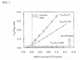
- FIG.3 shows a relation between P 120 /Fe 700 near the surface layer of the steel sheet and the addition amount of P.
- P is enriched in the surface layer when the P addition amount is not less than 0.03 mass% to bring about P 120 /Fe 700 exceeding 0.02. From this result, it is considered that the reason why the iron loss W 10/400 is decreased by the stress relief annealing in the steel sheet having the P addition amount of not less than 0.03 mass% is due to the fact that penetration of N from the atmosphere into the steel is inhibited by P enriched on the surface layer through the finish annealing and hence the fine Si 3 N 4 is not precipitated.
- C is a harmful element causing magnetic aging to deteriorate magnetic properties of a product sheet, so that it is limited to not more than 0.005 mass% in the invention. It is preferably not more than 0.003 mass%.
- Si is an element effective for increasing a specific resistance of the steel sheet to decrease an iron loss.
- Al as an element increasing an electric resistance like Si is not added, and hence Si is added in an amount of not less than 1.5 mass%.
- steel is remarkably embrittled by an addition exceeding 6.0 mass%. Therefore, Si is a range of 1.5-6.0 mass%. Preferably, it is 1.5-4.0 mass%.
- Mn is necessary to be added in an amount of not less than 0.05 mass% for preventing red brittleness in the hot rolling. When it exceeds 2.0 mass%, however, the magnetic flux density is decreased and embrittlement becomes prominent. Therefore, Mn is a range of 0.05-2.0 mass%. Preferably, it is a range of 0.05-1.5 mass%.
- P is an element effective for ensuring the crystal grain growth properties in the stress relief annealing as described above, and it is necessary to be added in an amount of not less than 0.03 mass%. When it exceeds 0.15 mass%, however, steel is embrittled to hinder the cold rolling. Therefore, P is a range of 0.03-0.15 mass%. Preferably, it is a range of 0.03-0.10 mass%.
- S is a harmful element forming sulfides such as MnS and the like to increase the iron loss, so that an upper limit is set to 0.005 mass%. Preferably, it is not more than 0.003 mass%.
- N forms nitrides and blocks the grain growth to deteriorate the iron loss properties, so that it is limited to not more than 0.005 mass%. Preferably, it is not more than 0.003 mass%.
- fine AlN is formed to block the grain growth and damage magnetic properties, so that it is limited to not more than 0.005 mass%. Preferably, it is not more than 0.003 mass%.
- the remainder other than the above essential ingredients is Fe and inevitable impurities.
- one or two of Sn and Sb can be contained in the following range.
- Each of Sn and Sb is an element improving the texture to increase the magnetic flux density.
- each element is preferable to be added at least in an amount of not less than 0.005 mass%. When it exceeds 0.2 mass%, however, the above effect is saturated. Therefore, when Sn and/or Sb are added, it is preferable to be add in the above range. More preferably, Sn is a range of 0.01-0.15 mass% and Sb is a range of 0.01-0.15 mass%.
- the non-oriented electrical steel sheet according to the invention can be produced by a well-known method as long as a slab having P content in the above proper range is used as a raw steel material.
- it can be produced by a method wherein molten steel adjusted to have the above chemical composition through a usual refining process of melting a steel in a converter, an electric furnace or the like and subjecting to a secondary refining in a degassing facility or the like is shaped into a slab by a continuous casting method and hot rolled to form a hot rolled sheet, which is subjected to a hot band annealing, if necessary, pickled, cold rolled to form a cold rolled sheet, and then subjected to a finish annealing.
- the sheet thickness of the steel sheet after the hot rolling is preferably a range of 1.0-5.0 mm.
- it is less than 1.0 mm, rolling troubles are increased in the hot rolling, while when it exceeds 5.0 mm, the cold rolling reduction becomes extremely high to deteriorate the texture.
- a soaking temperature is a range of 900-1200°C.
- 900°C the effect of the hot band annealing is small and the magnetic properties are not sufficiently improved, while when it exceeds 1200°C, it becomes disadvantageous costly, and further the surface defects are caused due to scales. More preferably, it is a range of 950-1050°C.
- the winding temperature of the coil is preferably not lower than 600°C and more preferably not lower than 620°C.
- the upper limit of the winding temperature is preferable to be not higher than 750°C from a viewpoint of preventing scale residue caused in the pickling of the hot rolled sheet.
- the cold rolling after the hot rolling or hot band annealing is preferably conducted once or two or more interposing an intermediate annealing therebetween.
- the final cold rolling is preferable to be a warm rolling conducted by raising the sheet temperature to about 200°C for the purpose of improving the magnetic flux density if there is no problem in the cost on the restriction of installation or production.
- the sheet thickness of the cold rolled sheet is a range of 0.1-1.0 mm.
- the productivity is decreased, while when it exceeds 1.0 mm, the effect of decreasing the iron loss is small.
- the finish annealing applied to the cold rolled sheet with the final sheet thickness it is preferable to adopt a continuous annealing of soaking the sheet at a temperature of 700-1100°C for 1-300 seconds.
- the soaking temperature is lower than 700°C, recrystallization is not sufficiently promoted, and good magnetic properties cannot be obtained, and further an effect of correcting the shape in the continuous annealing cannot be sufficiently obtained.
- the soaking temperature is 800-1100°C and the soaking time is 1-100 seconds.
- the temperature and the time of the finish annealing is desirable to be low and short, respectively, as long as the iron loss is accepted for ensuring the strength of the steel sheet after the finish annealing.
- the atmosphere during the soaking in the continuous annealing is preferable to be a non-oxidizing atmosphere having an oxygen potential P H2O /P H2 of not more than 0.001, because if it is an oxidizing atmosphere, oxides violently grown in the surface layer of the steel sheet block the grain growth and the iron loss properties is deteriorated. More preferably, it is not more than 0.0005.
- the atmosphere in the cooling after the soaking is necessary to be an oxidizing atmosphere having an oxygen potential P H2O /P H2 of not less than 0.001 for promoting segregation of P into the surface layer of the steel sheet. Preferably, it is not less than 0.003.
- P H2O /P H2 is too high, unevenness of oxidation called "gas mark" is caused in the surface layer of the steel sheet to damage the appearance as a product, so that the upper limit is preferably about 5.
- the control of the atmosphere in the cooling is necessary to be performed between 700°C and 500°C.
- the reason of setting to not lower than 500°C is due to the fact that decarburization is necessary to be caused in the surface layer for promoting P segregation, while the reason of setting to not higher than 700°C is due to the fact that when the atmosphere at a temperature exceeding 700°C is an oxidizing atmosphere, oxides violently grown in the surface layer of the steel sheet block the grain growth and the iron loss properties is deteriorated.
- it is a range of 650°C-550°C.
- the time for the cooling is necessary to be a range of 1-300 seconds. When it is less than 1 second, decarburization is not promoted, while when it exceeds 300 seconds, the productivity lowers. Moreover, it is preferable to conduct the cooling for not less than 5 seconds for sufficiently promoting the decarburization in the surface layer of the steel sheet to ensure the crystal grain growth properties. Preferably, it is a range of 5-100 seconds.
- a ratio (P 120 /Fe 700 ) of a peak to peak height P 120 of P near to an electronic energy of 120 eV to a peak to peak height Fe 700 of Fe near to an electronic energy of 700 eV in an Auger differential spectrum obtained by analyzing the steel sheet surface with an Auger electron spectroscopy is not less than 0.02.
- the ratio (P 120 /Fe 700 ) is preferable to be not less than 0.03 for further enhancing the crystal grain growth in the stress relief annealing.
- the steel sheet after the finish annealing produced as above has a high strength because P is added and the crystal grains are fine. Therefore, the steel sheet after the finish annealing can be used as a rotor core material as it is.
- the steel sheet is preferable to have a yield stress (upper yield point) of not less than 400 MPa, more preferably not less than 420 MPa in order to resist against centrifugal force due to high speed rotation of the motor.
- the yield stress is a value measured by subjecting a test specimen defined by JIS Z2201 (preferably JIS No. 5 test specimen) to a tensile test defined by JIS Z2241.
- the steel sheet after the finish annealing is high in the strength and has a property that the crystal grain growth properties in the stress relief annealing are excellent because the added P is segregated into the surface layer of the steel sheet in the finish annealing.
- the steel sheet after the finish annealing has a low iron loss when the stress relief annealing is performed, and can be used as a stator core material.
- the non-oriented electrical steel sheet after the finish annealing is punched out to provide iron core materials for the rotor core and stator core simultaneously.
- a rotor core having a high strength can be obtained by laminating and assembling the punched-out rotor core materials, while a stator core having a low iron loss can be obtained by laminating and assembling the punched-out stator core materials and then subjecting to a stress relief annealing.
- the stress relief annealing may be conducted under conditions of a usual manner and is not particularly limited. For example, it is preferable to be conducted at a temperature of 700-900°C for 0.1-10 hours in an inert gas atmosphere.
- the rotor core may be subjected to a stress relief annealing, but it is preferably not subjected thereto in order to maintain the high strength.
- an insulation coating to the surface of the steel sheet.
- an organic coating containing a resin for ensuring a good punchability while a semi-organic or an inorganic coating is preferable to be applied when the weldability is considered important.
- a molten steel having a chemical composition shown in Table 1 is prepared through blowing in a convertor and degassing treatment and shaped into a slab by a continuous casting method. Then, the slab is reheated at 1140°C for 1 hour and hot rolled to form a hot rolled sheet having a sheet thickness of 2.0 mm, which is subjected to a hot band annealing at 1000°C for 30 seconds, pickled and cold rolled to obtain a cold rolled sheet having a sheet thickness of 0.25 mm.
- the cold rolled sheet is subjected to a finish annealing by holding at a temperature of 700-900°C for 10 seconds in a non-oxidizing atmosphere with an oxygen potential P H2O /P H2 of 0.0005 as an atmosphere of a soaking zone and then cooling from 700°C to 500°C for 5-250 seconds in a non-oxidizing atmosphere having an oxygen potential P H2O /P H2 of 0.0003 or in an oxidizing atmosphere having an oxygen potential P H2O /P H2 of 0.003-3.0 to thereby obtain a cold rolled annealed sheet.
- Table 2 No. 22 in Table 2 is an example of conducting a self-annealing at 650°C for 1 hour instead of the hot band annealing, and No.23 is an example of conducting no annealing after the hot rolling.
- magnetic properties (iron loss W 10/400 and magnetic flux density B 50 ) are measured by a 25 cm Epstein test method, while a yield stress is measured by a tensile test using a JIS No. 5 specimen.
- the cold rolled annealed sheet is subjected to a stress relief annealing in a N 2 atmosphere at 750°C for 2 hours, and then W 10/400 and magnetic flux density B 50 are measured by a 25 cm Epstein test method.
- Inventive steel 2 0.0029 3.00 0.046 0.022 0.0016 0.0022 0.0008 tr. tr.
- Inventive steel 4 0.0030 2.98 0.051 0.142 0.0021 0.0019 0.0008 tr. tr. Inventive steel 5 0.0033 3.00 0.048 0.172 0.0020 0.0018 0.0007 tr. tr. Comparative steel 6 0.0027 1.56 0.046 0.094 0.0022 0.0020 0.0009 tr. tr. Inventive steel 7 0.0027 2.05 0.056 0.095 0.0022 0.0023 0.0010 tr. tr. Inventive steel 8 0.0026 4.03 0.052 0.090 0.0020 0.0016 0.0010 tr. tr. Inventive steel 9 0.0028 3.03 0.562 0.093 0.0019 0.0016 0.0009 tr.
- Comparative steel 15 0.0030 2.97 0.058 0.098 0.0016 0.0024 0.0007 0.009 tr.
- Inventive steel 16 0.0027 3.05 0.051 0.096 0.0017 0.0022 0.0008 0.183 tr.
- Inventive steel 17 0.0030 2.99 0.046 0.097 0.002 0.0018 0.0008 tr.
- Inventive steel 18 0.0031 2.97 0.057 0.092 0.0017 0.0018 0.0009 tr.
- 0.190 Inventive steel 19 0.0031 3.02 0.055 0.093 0.0017 0.0020 0.0009 0.036 0.031
- Inventive steel 20 0.0027 2.98 0.045 0.095 0.0023 0.0020 0.0010 tr. tr.
- Inventive steel 26 0.0033 3.02 0.051 0.059 0.0020 0.0018 0.0008 tr. tr.
- Inventive steel 27 0.0027 2.99 0.055 0.032 0.0021 0.0023 0.0008 tr. tr.
- Inventive steel 28 0.0028 3.03 0.056 0.056 0.0018 0.0023 0.0006 tr. tr.
- Inventive steel 29 0.0026 2.97 0.045 0.031 0.0019 0.0023 0.0006 tr. tr.
- Inventive steel 30 0.0025 2.96 0.049 0.058 0.0019 0.0017 0.0007 tr. tr.
- Inventive steel 31 0.0032 2.98 0.056 0.096 0.0016 0.0018 0.0006 tr. tr.
- Inventive steel 32 0.0035 3.05 0.056 0.091 0.0017 0.0021 0.0009 tr. tr.
- Inventive steel 33 0.0026 2.98 0.046 0.097 0.0020 0.0018 0.0007 tr. tr.
- Inventive steel 34 0.0030 2.97 0.054 0.096 0.0021 0.0022 0.0008 tr. tr.
- a non-oriented electrical steel sheet having a high strength after the finish annealing and a low iron loss after the stress relief annealing can be stably produced by subjecting a steel sheet having a chemical composition adapted to the invention to the finish annealing under the conditions adapted to the invention, so that rotor core materials and stator core materials can be obtained simultaneously from the same raw material steel sheet.
Landscapes
- Chemical & Material Sciences (AREA)
- Engineering & Computer Science (AREA)
- Materials Engineering (AREA)
- Mechanical Engineering (AREA)
- Metallurgy (AREA)
- Organic Chemistry (AREA)
- Physics & Mathematics (AREA)
- Crystallography & Structural Chemistry (AREA)
- Thermal Sciences (AREA)
- Manufacturing & Machinery (AREA)
- Power Engineering (AREA)
- Electromagnetism (AREA)
- Dispersion Chemistry (AREA)
- Soft Magnetic Materials (AREA)
- Manufacturing Of Steel Electrode Plates (AREA)
- Iron Core Of Rotating Electric Machines (AREA)
Abstract
Description
- This invention relates to a non-oriented electrical steel sheet and a production method therefor as well as a motor core, and more particularly to a non-oriented electrical steel sheet having excellent magnetic properties after stress relief annealing and a production method therefor as well as a motor core (rotor core and stator core) produced by using the non-oriented electrical steel sheet.
- With high global demand in recent years for energy saving on electrical machinery, a non-oriented electrical steel sheet used as an iron core (motor core) in a rotary machine has been also demanded to have more excellent magnetic properties. Recently, a motor for an electric vehicle has a strong need for downsizing and high output, so that it is designed to gain motor torque by increasing the rotation number of the motor.
- The motor core is divided into a stator core and a rotor core. However, the motor for the electric vehicle has an outer diameter larger than that of the conventional one to act a large centrifugal force, or a very narrow portion of 1-2 mm exists in an outer periphery of the rotor core depending on the structure thereof, so that the non-oriented electrical steel sheet used in the rotor core is required to have higher strength than before. On the other hand, in order to reduce the motor size and save energy, the stator core is required to have a low iron loss. To this end, it is ideal that the steel sheet used for the motor core has a high strength for the rotor core and a low iron loss for the stator core.
- As described above, even when the electrical steel sheet is used in the same motor core, the required characteristics are largely different between the rotor core and the stator core. In order to increase a material yield in the production of the motor core, therefore, it is desirable that rotor core materials and stator core materials are simultaneously taken out from the same raw steel sheet by punching and then assembled into a rotor core and a stator core by lamination, respectively.
- As a method for producing the aforementioned non-oriented electrical steel sheet having a high strength and a low iron loss, for example, Patent Document 1 proposes a method wherein a non-oriented electrical steel sheet with a high strength is first produced and rotor core materials are taken out therefrom and thereafter a non-oriented electrical steel sheet with a low iron loss is produced by subjecting the steel sheet to a stress relief annealing and stator core materials are taken out therefrom. In this method, impurity elements (Ti, S, N, V, Nb, Zr, As) contained in the steel are reduced to an extremely low level for promoting crystal grain growth in the stress relief annealing, and further a skin pass rolling is performed before the stress relief annealing.
- Recently, there is a movement that the used motor core is melted to reuse in a motor frame as a cast metal from a viewpoint of recycling the motor. However, the electrical steel sheet disclosed in Patent Document 1 is added with Al, so that there is a problem that the viscosity of the molten steel is increased at the time of casting to cause shrinkage cavities when it is reused. Thus, it is desirable that Al is not substantially added when the motor core is recycled as a foundry pig.
- Patent Document 2 discloses a non-oriented electrical steel sheet being substantially free from Al, which is capable of taking out rotor core materials and stator core materials therefrom. This technique uses a method wherein a high-strength non-oriented steel sheet is first produced and rotor core materials are taken out therefrom and thereafter the residual steel sheet is subjected to a stress relief annealing for taking out stator core materials like Patent Document 1. It is characterized by limiting Si. Mn, C, Sol. Al and N contents in order to promote crystal grain growth in the stress relief annealing and further controlling the number density of ductile inclusions inhibiting the grain growth.
-
- Patent Document 1: Japanese Patent No.
5228379 - Patent Document 2: Japanese Patent No.
4718749 - However, the method disclosed in the Patent Document 2 has a problem that the non-oriented electrical steel sheet having a low iron loss cannot be produced because Si content effective for reducing the iron loss is limited to not more than 1.2 mass%.
- The invention is made in view of the above problems inherent to the conventional techniques, and the object thereof is to provide a non-oriented electrical steel sheet capable of simultaneously taking out rotor core materials having a high strength and stator core materials having a low iron loss from the same raw steel sheet despite that the steel sheet is substantially free from Al, and an advantageous method of producing the same as well as a motor core (rotor core and stator core) produced by using the steel sheet.
- The inventors have made various studies focusing on the influence of the steel ingredients upon the strength and crystal grain growth properties for solving the above task. As a result, they have found that a non-oriented electrical steel sheet having a high content of Si and being substantially free from Al is added with a predetermined amount of P to increase crystal grain growth properties in a stress relief annealing, whereby rotor core materials having a high strength can be taken out from the steel sheet after finish annealing and stator core materials can be taken out from the steel sheet after stress relief annealing simultaneously, and it is important to segregate P in the surface layer of the steel sheet in the finish annealing, and thus the invention has been accomplished.
- That is, the invention is a non-oriented electrical steel sheet is having a chemical composition comprising C: not more than 0.005 mass%, Si: 1.5-6.0 mass%, Mn: 0.05-2.0 mass%, P: 0.03-0.15 mass%, S: not more than 0.005 mass%, N: not more than 0.005 mass%, Al: not more than 0.005 mass% and the remainder being Fe and inevitable impurities, wherein a ratio (P120/Fe700) of a peak to peak height P120 of P near to an electronic energy of 120 eV to a peak to peak height Fe700 of Fe near to an electronic energy of 700 eV in an Auger differential spectrum obtained by analyzing a surface of the steel sheet after a finish annealing by Auger electron spectroscopy is not less than 0.02.
- The non-oriented electrical steel sheet according to the invention is characterized by containing one or two selected from Sn: 0.005-0.2 mass% and Sb: 0.005-0.2 mass% in addition to the above chemical composition.
- The non-oriented electrical steel sheet according to the invention is characterized in that a yield strength is not less than 400 MPa.
- Also, the invention proposes a method for producing a non-oriented electrical steel sheet by hot rolling a slab having the above-described chemical composition, pickling without a hot band annealing or after a hot band annealing or self-annealing, performing one cold rolling or two or more cold rollings interposing an intermediate annealing therebetween, performing a finish annealing and forming an insulation coating, characterized in that cooling from 700°C to 500°C in the finish annealing is conducted in an oxidizing atmosphere having an oxygen potential PH2O/PH2 of not less than 0.001 for 1-300 seconds.
- The invention is a rotor core for a rotary machine formed by punching out rotor core materials from any one of the non-oriented electrical steel sheets described above and laminating them.
- The invention is a stator core for a rotary machine formed by punching out stator core materials from any one of the non-oriented electrical steel sheets described above, laminating them and subjecting to a stress relief annealing.
- According to the invention, it is possible to produce a non-oriented electrical steel sheet having a high strength after a finish annealing and a low iron loss after a stress relief annealing, so that rotor core materials having a high strength and stator core materials having a low iron loss can be taken out from the same raw material steel sheet simultaneously, which can contribute to an improvement in a material yield of the motor core and a reduction in a material cost.
-
-
FIG. 1 is a graph showing a relation between an addition amount of Si and an iron loss W10/400 before and after a stress relief annealing. -
FIG.2 is a graph showing a relation between an addition amount of P and an iron loss W10/400 before and after a stress relief annealing. -
FIG.3 is a graph showing a relation between an addition amount of P and P120/Fe700 near to the surface of the steel sheet after the finish annealing. - There will be described experiments building a momentum for developing the invention.
- Firstly, an experiment is conducted for studying an influence of Si on the crystal grain growth properties in the stress relief annealing.
- A steel containing C: 0.003 mass%, Mn: 0.05 mass%, P: 0.01 mass%, S: 0.002 mass%, N: 0.002 mass% and Al: 0.001 mass% and added with Si in an amount varying within a range of 0.5-4.0 mass% is melted laboratorially to provide a steel ingot, which is hot rolled to form a hot rolled sheet having a sheet thickness of 2.0 mm.
- Then, the hot rolled sheet is subjected to a hot band annealing at 1000°C for 30 seconds, pickled and cold rolled to form a cold rolled sheet having a sheet thickness of 0.25 mm, which is thereafter subjected to a finish annealing at 800°C for 10 seconds in a non-oxidizing atmosphere having an oxygen potential PH2O/PH2 of 0.0005 (10 vol% of H2 - 90 vol% of N2 and a dew point of - 50°C) to provide a non-oriented electrical steel sheet, and an iron loss W10/400 thereof is measured by a 25 cm Epstein method.
- Next, the steel sheet is subjected to a stress relief annealing in an N2 atmosphere at 750°C for 2 hours, and an iron loss W10/400 thereof is again measured by a 25 cm Epstein method.
-
FIG. 1 shows a relation between the iron loss W10/400 before and after the stress relief annealing and the addition amount of Si. As seen from this figure, when the addition amount of Si is 0.5-1.5 mass%, the ion loss W10/400 is decreased by the stress relief annealing, while when the addition amount of Si is not less than 1.5 mass%, the iron loss W10/400 is not decreased. - In order to examine this cause, the structure of the steel sheet after the stress relief annealing is observed by TEM, and as a result, a large number of fine Si3N4 precipitates are found near the surface layer in a steel sheet having a Si addition amount of not less than 1.5 mass%, while the fine precipitates are not found in a steel sheet having a Si addition amount of 0.5-1.5 mass%. It is revealed from this result that in the steel sheet having a large addition amount of Si, N penetrated from the atmosphere into the steel reacts with Si in the steel to precipitate fine Si3N4, whereby the grain growth is blocked and the iron loss properties is not improved.
- Next, the inventors have studied an influence of an atmosphere in the stress relief annealing and an addition amount of P upon the crystal grain growth properties.
- A steel containing C: 0.003 mass%, Si: 3.0 mass%, Mn: 0.05 mass%, S: 0.002 mass%, N: 0.002 mass%, Al: 0.001 mass% and added with P in an amount varying within a range of 0.01-0.15 mass% is melted laboratorially to provide a steel ingot, which is hot rolled to form a hot rolled sheet having a sheet thickness of 2.0 mm.
- Then, the hot rolled sheet is subjected to a hot band annealing at 1000°C for 30 seconds, pickled and cold rolled to form a cold rolled sheet having a sheet thickness of 0.25 mm, which is thereafter subjected to a finish annealing at 800°C for 10 seconds in a non-oxidizing atmosphere having an oxygen potential PH2O/PH2 of 0.0005 (10 vol% of H2 - 90 vol% of N2 and a dew point of -50°C) to provide a non-oriented electrical steel sheet. In this case, the cooling from 700°C to 500°C is conducted for 10 seconds on the following 3 conditions:
- Condition A: A non-oxidizing atmosphere having PH2O/PH2 of 0.0005 (10 vol% of H2 - 90 vol% of N2 and a dew point of -50°C);
- Condition B: An oxidizing atmosphere having PH2O/PH2 of 0.01 (2 vol% of H2 - 98 vol% of N2 and a dew point of -40°C); and
- Condition C: An oxidizing atmosphere having PH2O/PH2 of 0.5 (0.1 vol% of H2- 99.9 vol% of N2 and a dew point of -30°C).
- With respect to the thus obtained steel sheets after the finish annealing is measured an iron loss W10/400 by a 25 cm Epstein method. Moreover, the steel sheet is subjected to a stress relief annealing in a N2 atmosphere at 750°C for 2 hours, and an iron loss W10/400 is again measured by a 25 cm Epstein method.
-
FIG. 2 shows a relation between the iron loss W10/400 before and after the stress relief annealing and the addition amount of P. Since the iron loss W10/400 before the stress relief annealing is almost constant irrespective of PH2O/PH2 in the atmosphere during the cooling, an iron loss W10/400 at PH2O/PH2 of 0.0005 is shown inFIG. 2 . - As seen from
FIG. 2 , the iron loss properties in the steel sheet cooled at PH2O/PH2 of 0.0005 is not improved so much even in the stress relief annealing, while the iron loss in the steel sheet cooled at PH2O/PH2 of 0.01 or 0.5 is largely decreased when the addition amount of P is not less than 0.03 mass%. - As the structure of the steel sheet after the stress relief annealing is observed by TEM, fine Si3N4 precipitates are found at any case of PH2O/PH2 of 0.0005, 0.01 and 0.5 in the steel sheets having a P addition amount of less than 0.03 mass%, while Si3N4 precipitates are not found in either case of PH2O/PH2 of 0.01 or 0.5 in the steel sheets having a P addition amount of not less than 0.03 mass%.
- In order to examine this cause, a segregation amount of P in the surface layer of the steel sheet after the finish annealing is analyzed by an Auger electron stereoscopy (AES). Moreover, the segregation amount of P is evaluated by a ratio (P120/Fe700) of a peak to peak height P120 of P near to an electronic energy of 120 eV to a peak to peak height Fe700 of Fe near to an electronic energy of 700 eV in an Auger differential spectrum. Here, the Auger differential spectrum is a spectrum obtained by differentiating an Auger spectrum.
-
FIG.3 shows a relation between P120/Fe700 near the surface layer of the steel sheet and the addition amount of P. As seen from this figure, in the steel sheets cooled at PH2O/PH2 of 0.01 or 0.5, P is enriched in the surface layer when the P addition amount is not less than 0.03 mass% to bring about P120/Fe700 exceeding 0.02. From this result, it is considered that the reason why the iron loss W10/400 is decreased by the stress relief annealing in the steel sheet having the P addition amount of not less than 0.03 mass% is due to the fact that penetration of N from the atmosphere into the steel is inhibited by P enriched on the surface layer through the finish annealing and hence the fine Si3N4 is not precipitated. - The reason why the segregation of P into the surface layer of the steel sheet is promoted by rendering the atmosphere in the cooling during the finish annealing into an oxidizing atmosphere is not clear sufficiently, but it is considered due to the fact that decarburization is caused in the surface layer of the steel sheet in the oxidizing atmosphere to promote the segregation of P.
- It can be seen from the above results that the segregation of P into the surface layer of the steel sheet in the finish annealing is extremely effective for ensuring the crystal grain growth properties in the subsequent stress relief annealing.
- Next, the chemical composition of the non-oriented electrical steel sheet according to the invention will be explained.
- C is a harmful element causing magnetic aging to deteriorate magnetic properties of a product sheet, so that it is limited to not more than 0.005 mass% in the invention. It is preferably not more than 0.003 mass%.
- Si is an element effective for increasing a specific resistance of the steel sheet to decrease an iron loss. In the invention, Al as an element increasing an electric resistance like Si is not added, and hence Si is added in an amount of not less than 1.5 mass%. However, steel is remarkably embrittled by an addition exceeding 6.0 mass%. Therefore, Si is a range of 1.5-6.0 mass%. Preferably, it is 1.5-4.0 mass%.
- Mn is necessary to be added in an amount of not less than 0.05 mass% for preventing red brittleness in the hot rolling. When it exceeds 2.0 mass%, however, the magnetic flux density is decreased and embrittlement becomes prominent. Therefore, Mn is a range of 0.05-2.0 mass%. Preferably, it is a range of 0.05-1.5 mass%.
- P is an element effective for ensuring the crystal grain growth properties in the stress relief annealing as described above, and it is necessary to be added in an amount of not less than 0.03 mass%. When it exceeds 0.15 mass%, however, steel is embrittled to hinder the cold rolling. Therefore, P is a range of 0.03-0.15 mass%. Preferably, it is a range of 0.03-0.10 mass%.
- S is a harmful element forming sulfides such as MnS and the like to increase the iron loss, so that an upper limit is set to 0.005 mass%. Preferably, it is not more than 0.003 mass%.
- N forms nitrides and blocks the grain growth to deteriorate the iron loss properties, so that it is limited to not more than 0.005 mass%. Preferably, it is not more than 0.003 mass%.
- When a slight amount of Al exits, fine AlN is formed to block the grain growth and damage magnetic properties, so that it is limited to not more than 0.005 mass%. Preferably, it is not more than 0.003 mass%.
- In the non-oriented electrical steel sheet according to the invention, the remainder other than the above essential ingredients is Fe and inevitable impurities. However, one or two of Sn and Sb can be contained in the following range.
- Each of Sn and Sb is an element improving the texture to increase the magnetic flux density. In order to obtain the above effect, each element is preferable to be added at least in an amount of not less than 0.005 mass%. When it exceeds 0.2 mass%, however, the above effect is saturated. Therefore, when Sn and/or Sb are added, it is preferable to be add in the above range. More preferably, Sn is a range of 0.01-0.15 mass% and Sb is a range of 0.01-0.15 mass%.
- The production method of the non-oriented electrical steel sheet according to the invention will be described below.
- The non-oriented electrical steel sheet according to the invention can be produced by a well-known method as long as a slab having P content in the above proper range is used as a raw steel material. For example, it can be produced by a method wherein molten steel adjusted to have the above chemical composition through a usual refining process of melting a steel in a converter, an electric furnace or the like and subjecting to a secondary refining in a degassing facility or the like is shaped into a slab by a continuous casting method and hot rolled to form a hot rolled sheet, which is subjected to a hot band annealing, if necessary, pickled, cold rolled to form a cold rolled sheet, and then subjected to a finish annealing.
- The sheet thickness of the steel sheet after the hot rolling (hot rolled sheet) is preferably a range of 1.0-5.0 mm. When it is less than 1.0 mm, rolling troubles are increased in the hot rolling, while when it exceeds 5.0 mm, the cold rolling reduction becomes extremely high to deteriorate the texture.
- In the case of performing the hot band annealing, it is preferable that a soaking temperature is a range of 900-1200°C. When it is lower than 900°C, the effect of the hot band annealing is small and the magnetic properties are not sufficiently improved, while when it exceeds 1200°C, it becomes disadvantageous costly, and further the surface defects are caused due to scales. More preferably, it is a range of 950-1050°C.
- Moreover, a self-annealing of a coil wound after the hot rolling may be utilized instead of the hot band annealing. In this case, the winding temperature of the coil is preferably not lower than 600°C and more preferably not lower than 620°C. The upper limit of the winding temperature is preferable to be not higher than 750°C from a viewpoint of preventing scale residue caused in the pickling of the hot rolled sheet.
- The cold rolling after the hot rolling or hot band annealing is preferably conducted once or two or more interposing an intermediate annealing therebetween. In particular, the final cold rolling is preferable to be a warm rolling conducted by raising the sheet temperature to about 200°C for the purpose of improving the magnetic flux density if there is no problem in the cost on the restriction of installation or production.
- It is preferable that the sheet thickness of the cold rolled sheet (final sheet thickness) is a range of 0.1-1.0 mm. When it is less than 0.1 mm, the productivity is decreased, while when it exceeds 1.0 mm, the effect of decreasing the iron loss is small.
- As the finish annealing applied to the cold rolled sheet with the final sheet thickness, it is preferable to adopt a continuous annealing of soaking the sheet at a temperature of 700-1100°C for 1-300 seconds. When the soaking temperature is lower than 700°C, recrystallization is not sufficiently promoted, and good magnetic properties cannot be obtained, and further an effect of correcting the shape in the continuous annealing cannot be sufficiently obtained. On the other hand, when it exceeds 1100°C, the crystal grains are coarsened to decrease the strength or lower the toughness. It is more preferable that the soaking temperature is 800-1100°C and the soaking time is 1-100 seconds. Moreover, the temperature and the time of the finish annealing is desirable to be low and short, respectively, as long as the iron loss is accepted for ensuring the strength of the steel sheet after the finish annealing.
- The atmosphere during the soaking in the continuous annealing is preferable to be a non-oxidizing atmosphere having an oxygen potential PH2O/PH2 of not more than 0.001, because if it is an oxidizing atmosphere, oxides violently grown in the surface layer of the steel sheet block the grain growth and the iron loss properties is deteriorated. More preferably, it is not more than 0.0005.
- And also, the atmosphere in the cooling after the soaking is necessary to be an oxidizing atmosphere having an oxygen potential PH2O/PH2 of not less than 0.001 for promoting segregation of P into the surface layer of the steel sheet. Preferably, it is not less than 0.003. When PH2O/PH2 is too high, unevenness of oxidation called "gas mark" is caused in the surface layer of the steel sheet to damage the appearance as a product, so that the upper limit is preferably about 5.
- Moreover, the control of the atmosphere in the cooling is necessary to be performed between 700°C and 500°C. The reason of setting to not lower than 500°C is due to the fact that decarburization is necessary to be caused in the surface layer for promoting P segregation, while the reason of setting to not higher than 700°C is due to the fact that when the atmosphere at a temperature exceeding 700°C is an oxidizing atmosphere, oxides violently grown in the surface layer of the steel sheet block the grain growth and the iron loss properties is deteriorated. Preferably, it is a range of 650°C-550°C.
- And also, the time for the cooling is necessary to be a range of 1-300 seconds. When it is less than 1 second, decarburization is not promoted, while when it exceeds 300 seconds, the productivity lowers. Moreover, it is preferable to conduct the cooling for not less than 5 seconds for sufficiently promoting the decarburization in the surface layer of the steel sheet to ensure the crystal grain growth properties. Preferably, it is a range of 5-100 seconds.
- In the steel sheet cooled under the above conditions after the finish annealing, a ratio (P120/Fe700) of a peak to peak height P120 of P near to an electronic energy of 120 eV to a peak to peak height Fe700 of Fe near to an electronic energy of 700 eV in an Auger differential spectrum obtained by analyzing the steel sheet surface with an Auger electron spectroscopy is not less than 0.02. Moreover, the ratio (P120/Fe700) is preferable to be not less than 0.03 for further enhancing the crystal grain growth in the stress relief annealing.
- The steel sheet after the finish annealing produced as above has a high strength because P is added and the crystal grains are fine. Therefore, the steel sheet after the finish annealing can be used as a rotor core material as it is. Here, the steel sheet is preferable to have a yield stress (upper yield point) of not less than 400 MPa, more preferably not less than 420 MPa in order to resist against centrifugal force due to high speed rotation of the motor. The yield stress is a value measured by subjecting a test specimen defined by JIS Z2201 (preferably JIS No. 5 test specimen) to a tensile test defined by JIS Z2241.
- Further, the steel sheet after the finish annealing is high in the strength and has a property that the crystal grain growth properties in the stress relief annealing are excellent because the added P is segregated into the surface layer of the steel sheet in the finish annealing. Thus, the steel sheet after the finish annealing has a low iron loss when the stress relief annealing is performed, and can be used as a stator core material.
- The method of producing a motor core (rotor core and stator core) from the steel sheet after the finish annealing will be described below.
- The non-oriented electrical steel sheet after the finish annealing is punched out to provide iron core materials for the rotor core and stator core simultaneously. A rotor core having a high strength can be obtained by laminating and assembling the punched-out rotor core materials, while a stator core having a low iron loss can be obtained by laminating and assembling the punched-out stator core materials and then subjecting to a stress relief annealing.
- The stress relief annealing may be conducted under conditions of a usual manner and is not particularly limited. For example, it is preferable to be conducted at a temperature of 700-900°C for 0.1-10 hours in an inert gas atmosphere. The rotor core may be subjected to a stress relief annealing, but it is preferably not subjected thereto in order to maintain the high strength.
- Then, in order to decrease the iron loss in the steel sheet after the finish annealing, it is preferable to apply an insulation coating to the surface of the steel sheet. In this regard, it is preferable to apply an organic coating containing a resin for ensuring a good punchability, while a semi-organic or an inorganic coating is preferable to be applied when the weldability is considered important.
- A molten steel having a chemical composition shown in Table 1 is prepared through blowing in a convertor and degassing treatment and shaped into a slab by a continuous casting method. Then, the slab is reheated at 1140°C for 1 hour and hot rolled to form a hot rolled sheet having a sheet thickness of 2.0 mm, which is subjected to a hot band annealing at 1000°C for 30 seconds, pickled and cold rolled to obtain a cold rolled sheet having a sheet thickness of 0.25 mm. Next, the cold rolled sheet is subjected to a finish annealing by holding at a temperature of 700-900°C for 10 seconds in a non-oxidizing atmosphere with an oxygen potential PH2O/PH2 of 0.0005 as an atmosphere of a soaking zone and then cooling from 700°C to 500°C for 5-250 seconds in a non-oxidizing atmosphere having an oxygen potential PH2O/PH2 of 0.0003 or in an oxidizing atmosphere having an oxygen potential PH2O/PH2 of 0.003-3.0 to thereby obtain a cold rolled annealed sheet. Moreover, the details of the above production conditions are shown in Table 2. No. 22 in Table 2 is an example of conducting a self-annealing at 650°C for 1 hour instead of the hot band annealing, and No.23 is an example of conducting no annealing after the hot rolling.
- With respect to the cold rolled annealed sheet, magnetic properties (iron loss W10/400 and magnetic flux density B50) are measured by a 25 cm Epstein test method, while a yield stress is measured by a tensile test using a JIS No. 5 specimen.
- Furthermore, the cold rolled annealed sheet is subjected to a stress relief annealing in a N2 atmosphere at 750°C for 2 hours, and then W10/400 and magnetic flux density B50 are measured by a 25 cm Epstein test method.
Table 1 Steel No. Chemical composition (mass%) Remarks C Si Mn P S N Al Sn Sb 1 0.0025 3.02 0.046 0.095 0.0018 0.0023 0.0008 tr. tr. Inventive steel 2 0.0029 3.00 0.046 0.022 0.0016 0.0022 0.0008 tr. tr. Comparative steel 3 0.0030 2.98 0.052 0.031 0.0021 0.0021 0.0006 tr. tr. Inventive steel 4 0.0030 2.98 0.051 0.142 0.0021 0.0019 0.0008 tr. tr. Inventive steel 5 0.0033 3.00 0.048 0.172 0.0020 0.0018 0.0007 tr. tr. Comparative steel 6 0.0027 1.56 0.046 0.094 0.0022 0.0020 0.0009 tr. tr. Inventive steel 7 0.0027 2.05 0.056 0.095 0.0022 0.0023 0.0010 tr. tr. Inventive steel 8 0.0026 4.03 0.052 0.090 0.0020 0.0016 0.0010 tr. tr. Inventive steel 9 0.0028 3.03 0.562 0.093 0.0019 0.0016 0.0009 tr. tr. Inventive steel 10 0.0033 3.00 1.975 0.094 0.0022 0.0018 0.0009 tr. tr. Inventive steel 11 0.0030 2.97 0.058 0.091 0.0055 0.0019 0.0008 tr. tr. Comparative steel 12 0.0029 2.99 0.055 0.096 0.0025 0.0059 0.0010 tr. tr. Comparative steel 13 0.0031 2.99 0.050 0.100 0.0017 0.0020 0.0042 tr. tr. Inventive steel 14 0.0030 3.05 0.046 0.099 0.0023 0.0024 0.0054 tr. tr. Comparative steel 15 0.0030 2.97 0.058 0.098 0.0016 0.0024 0.0007 0.009 tr. Inventive steel 16 0.0027 3.05 0.051 0.096 0.0017 0.0022 0.0008 0.183 tr. Inventive steel 17 0.0030 2.99 0.046 0.097 0.002 0.0018 0.0008 tr. 0,012 Inventive steel 18 0.0031 2.97 0.057 0.092 0.0017 0.0018 0.0009 tr. 0.190 Inventive steel 19 0.0031 3.02 0.055 0.093 0.0017 0.0020 0.0009 0.036 0.031 Inventive steel 20 0.0027 2.98 0.045 0.095 0.0023 0.0020 0.0010 tr. tr. Inventive steel 21 0.0032 2.98 0.046 0.096 0.0020 0.0022 0.0009 tr. tr. Inventive steel 22 0.0033 3.03 0.052 0.092 0.0021 0.0020 0.0008 tr. tr. Inventive steel 23 0.0027 2.97 0.048 0.091 0.0020 0.0021 0.0009 tr. tr. Inventive steer 24 0.0029 3.00 0.051 0.092 0.0022 0.0017 0.0007 tr. tr. Inventive steel 25 0.0026 3.02 0.053 0.031 0.0019 0.0017 0.0009 tr. tr. Inventive steel 26 0.0033 3.02 0.051 0.059 0.0020 0.0018 0.0008 tr. tr. Inventive steel 27 0.0027 2.99 0.055 0.032 0.0021 0.0023 0.0008 tr. tr. Inventive steel 28 0.0028 3.03 0.056 0.056 0.0018 0.0023 0.0006 tr. tr. Inventive steel 29 0.0026 2.97 0.045 0.031 0.0019 0.0023 0.0006 tr. tr. Inventive steel 30 0.0025 2.96 0.049 0.058 0.0019 0.0017 0.0007 tr. tr. Inventive steel 31 0.0032 2.98 0.056 0.096 0.0016 0.0018 0.0006 tr. tr. Inventive steel 32 0.0035 3.05 0.056 0.091 0.0017 0.0021 0.0009 tr. tr. Inventive steel 33 0.0026 2.98 0.046 0.097 0.0020 0.0018 0.0007 tr. tr. Inventive steel 34 0.0030 2.97 0.054 0.096 0.0021 0.0022 0.0008 tr. tr. Inventive steel Table 2 Steel No Annealing after hot rolling" Finish annealing condition P120/Fe700 in surface layer of steel sheet after finish annealing Magnetic stress properties relief annealing before Magnetic after stress annealing properties Remarks Temperature in soaking zone (°C) Cooling time from 700°C to 500°C (s) PH20/PH2 during cooling from 700°C to 500°C Iron loss W10/400 (W/kg) Magnetic flux density B50(T) Yield stress (MPa) Iron loss W10/400 (W/kg) Magnetic flux density B10(T) 1 A 800 10 0.01 0.13 19.8 1.692 433 12.0 1.691 Inventive Example 2 A 800 10 0.01 0.01 20.0 1.692 434 19.0 1.692 Comparative Example 3 A 800 10 0.01 0.03 19.9 1.691 431 17.6 1.690 Inventive Example 4 A 800 10 0.01 0.22 19.8 1.691 429 11.8 1.691 Inventive Example 5 A 800 10 0.01 Cannot be measured with no rolling due to embrittlement Comparative Example 6 A 800 10 0.01 0.13 29.6 1.733 371 21.0 1.732 Inventive Example 7 A 800 10 0.01 0.13 25.2 1.720 390 16.9 1.719 Inventive Example 8 A 800 10 0.01 0.14 17.6 1.663 478 9.8 1.662 Inventive Example 9 A 800 10 0.01 0.12 19.2 1.683 448 11.3 1.682 Inventive Example 10 A 800 10 0.01 0.13 17.2 1.640 460 10.0 1.641 Inventive Example 11 A 800 10 0.01 0.12 23.8 1.653 475 19.1 1.653 Comparative Example 12 A 800 10 0.01 0.12 23.6 1.647 462 19.9 1.648 Comparative Example 13 A 800 10 0.01 0.13 21.2 1691 431 15.6 1.690 Inventive Example 14 A 800 10 0.01 0.14 23.1 1.693 430 19.6 1.690 Comparative Example 15 A 800 10 0.01 0.13 19.9 1.701 428 12.0 1.700 Inventive Example 16 A 800 10 0.01 0.12 20.0 1.711 431 11.9 1.710 Inventive Example 17 A 800 10 0.01 0.12 19.9 1.700 430 11.8 1.700 Inventive Example 18 A 800 10 0.01 0.13 19.8 1.710 427 11.9 1.710 Inventive Example 19 A 800 10 0.01 0.12 19.3 1.706 413 11.5 1.705 Inventive Example 20 A 700 10 0.01 0.12 22.3 1.690 463 11.9 1.693 Inventive Example 21 A 900 10 0.01 0.13 17.4 1.691 377 11.9 1.691 Inventive Example 22 B 800 10 0.01 0.13 19.9 1.677 430 12.0 1.677 Inventive Example 23 not conducted 800 10 0.01 0.12 19.8 1.665 432 11.9 1.665 Inventive Example 24 A 800 10 0.0003 0.01 19.9 1.691 432 19.0 1.690 Comparative Example 25 A 800 10 0.003 0.02 19.9 1.692 427 18.5 1.690 Inventive Example 26 A 800 10 0.003 0.08 19.9 1.692 430 16.3 1.691 Inventive Example 27 A 800 10 0.30 0.04 19.9 1.693 433 17.2 1.690 Inventive Example 28 A 800 10 0.30 0 09 19.9 1.691 429 13.1 1.691 Inventive Example 29 A 800 10 3.00 0.06 19.9 1.692 431 14.2 1.693 Inventive Example 30 A 800 10 3.00 0.15 19.9 1.692 428 11.8 1.693 Inventive Example 31 A 800 5 0.01 0.11 19.8 1.693 433 12.4 1.691 Inventive Example 32 A 800 60 0.01 0.15 19.9 1.691 433 11.9 1.692 Inventive Example 33 A 800 100 0.01 0.17 19.9 1.691 434 11.9 1.692 Inventive Example 34 A 800 250 0.01 0.21 19.9 1.691 428 11.8 1.690 Inventive Example *) Annealing after hot rolling; A: hot band annealing, B: self-annealing - The results of the magnetic flux density and the tensile test are shown in Table 2 together with the production conditions.
- As seen from Table 1 and Table 2, a non-oriented electrical steel sheet having a high strength after the finish annealing and a low iron loss after the stress relief annealing can be stably produced by subjecting a steel sheet having a chemical composition adapted to the invention to the finish annealing under the conditions adapted to the invention, so that rotor core materials and stator core materials can be obtained simultaneously from the same raw material steel sheet.
Claims (6)
- A non-oriented electrical steel sheet having a chemical composition comprising C: not more than 0.005 mass%, Si: 1.5-6.0 mass%, Mn: 0.05-2.0 mass%, P: 0.03-0.15 mass%, S: not more than 0.005 mass%, N: not more than 0.005 mass%, Al: not more than 0.005 mass% and the remainder being Fe and inevitable impurities, wherein a ratio (P120/Fe700) of a peak to peak height P120 of P near to an electronic energy of 120 eV to a peak to peak height Fe700 of Fe near to an electronic energy of 700 eV in an Auger differential spectrum obtained by analyzing a surface of the steel sheet after a finish annealing by an Auger electron spectroscopy is not less than 0.02.
- The non-oriented electrical steel sheet according to claim 1, characterized by containing one or two selected from Sn: 0.005-0.2 mass% and Sb: 0.005-0.2 mass% in addition to the chemical composition.
- The non-oriented electrical steel sheet according to claim 1 or 2, characterized in that a yield strength is not less than 400 MPa.
- A method of producing a non-oriented electrical steel sheet by hot rolling a slab having a chemical composition as claimed in claim 1 or 2, pickling without a hot band annealing or after a hot band annealing or a self-annealing, performing one cold rolling or two or more cold rollings interposing an intermediate annealing therebetween, performing a finish annealing, and forming an insulation coating, characterized in that a cooling from 700°C to 500°C in the finish annealing is conducted in an oxidizing atmosphere having an oxygen potential PH2O/PH2 of not less than 0.001 for 1-300 seconds.
- A rotor core for a rotary machine, characterized in that the rotor core is formed by punching out rotor core materials from a non-oriented electrical steel sheet as claimed in any one of claims 1-3 and laminating the rotor core materials.
- A stator core for a rotary machine, characterized in that the stator core is formed by punching out stator core materials from a non-oriented electrical steel sheet as claimed in any one of claims 1-3, laminating the stator core materials, and subjecting to a stress relief annealing.
Applications Claiming Priority (2)
| Application Number | Priority Date | Filing Date | Title |
|---|---|---|---|
| JP2015029478A JP6048699B2 (en) | 2015-02-18 | 2015-02-18 | Non-oriented electrical steel sheet, manufacturing method thereof and motor core |
| PCT/JP2016/050300 WO2016132753A1 (en) | 2015-02-18 | 2016-01-07 | Non-oriented electrical steel sheet, production method therefor, and motor core |
Publications (3)
| Publication Number | Publication Date |
|---|---|
| EP3260567A1 true EP3260567A1 (en) | 2017-12-27 |
| EP3260567A4 EP3260567A4 (en) | 2018-01-03 |
| EP3260567B1 EP3260567B1 (en) | 2019-05-08 |
Family
ID=56692432
Family Applications (1)
| Application Number | Title | Priority Date | Filing Date |
|---|---|---|---|
| EP16752142.6A Active EP3260567B1 (en) | 2015-02-18 | 2016-01-07 | Non-oriented electrical steel sheet, production method therefor, and motor core |
Country Status (8)
| Country | Link |
|---|---|
| US (1) | US10941458B2 (en) |
| EP (1) | EP3260567B1 (en) |
| JP (1) | JP6048699B2 (en) |
| KR (1) | KR101981874B1 (en) |
| CN (1) | CN107208230B (en) |
| RU (1) | RU2674181C1 (en) |
| TW (1) | TWI589707B (en) |
| WO (1) | WO2016132753A1 (en) |
Cited By (3)
| Publication number | Priority date | Publication date | Assignee | Title |
|---|---|---|---|---|
| EP3572535A4 (en) * | 2017-03-30 | 2020-01-08 | JFE Steel Corporation | METHOD FOR MANUFACTURING AN ELECTROMAGNETIC STEEL PLATE WITH NON-ORIENTED GRAINS, METHOD FOR MANUFACTURING ENGINE CORE AND ENGINE CORE |
| EP3913089A4 (en) * | 2019-01-16 | 2022-12-07 | Nippon Steel Corporation | GRAIN ORIENTED ELECTROMAGNETIC STEEL SHEET AND METHOD OF MANUFACTURING THEREOF |
| EP3656885B1 (en) | 2017-07-19 | 2025-04-23 | Nippon Steel Corporation | Non-oriented electrical steel sheet |
Families Citing this family (27)
| Publication number | Priority date | Publication date | Assignee | Title |
|---|---|---|---|---|
| JP6048699B2 (en) | 2015-02-18 | 2016-12-21 | Jfeスチール株式会社 | Non-oriented electrical steel sheet, manufacturing method thereof and motor core |
| RU2686424C1 (en) * | 2015-08-04 | 2019-04-25 | ДжФЕ СТИЛ КОРПОРЕЙШН | Method for production of sheets of non-oriented electrical steel having excellent magnetic properties |
| JP6658471B2 (en) * | 2016-11-25 | 2020-03-04 | トヨタ自動車株式会社 | Method for manufacturing rotor core and method for manufacturing motor core |
| CN109983143A (en) * | 2016-11-25 | 2019-07-05 | 杰富意钢铁株式会社 | Non orientation electromagnetic steel plate and its manufacturing method |
| CN110249063A (en) * | 2017-02-07 | 2019-09-17 | 杰富意钢铁株式会社 | The manufacturing method of non orientation electromagnetic steel plate and the manufacturing method of motor iron core and motor iron core |
| TWI658152B (en) * | 2017-03-07 | 2019-05-01 | 日商新日鐵住金股份有限公司 | Non-directional electrical steel sheet and method for manufacturing non-oriented electrical steel sheet |
| JP6738047B2 (en) | 2017-05-31 | 2020-08-12 | Jfeスチール株式会社 | Non-oriented electrical steel sheet and its manufacturing method |
| NL1042618B1 (en) * | 2017-11-02 | 2019-05-13 | Bosch Gmbh Robert | Multi-layer blanking process for manufacturing metal parts |
| KR101842418B1 (en) | 2018-01-10 | 2018-03-26 | 포항공과대학교 산학협력단 | Non-oriented electrical steels and method for manufacturing the same |
| JP7119519B2 (en) * | 2018-04-11 | 2022-08-17 | 日本製鉄株式会社 | Non-oriented electrical steel sheet, stator core, rotor core and manufacturing method thereof |
| JP7139692B2 (en) * | 2018-05-30 | 2022-09-21 | 日本製鉄株式会社 | Steel for induction hardening, materials for induction hardening parts, and induction hardening parts |
| MX2021004862A (en) | 2018-10-31 | 2021-06-15 | Jfe Steel Corp | Non-oriented electromagnetic steel sheet and method for manufacturing same, and motor core and method for manufacturing same. |
| JP7092095B2 (en) * | 2018-11-09 | 2022-06-28 | Jfeスチール株式会社 | Motor core and its manufacturing method |
| EP3913079B1 (en) * | 2019-01-17 | 2023-09-20 | Nippon Steel Corporation | Non-oriented electrical steel sheet, segmented stator, and rotating electrical machine |
| CN120624762A (en) * | 2019-06-28 | 2025-09-12 | 杰富意钢铁株式会社 | Method for manufacturing motor core and motor core |
| CN110205462A (en) * | 2019-06-28 | 2019-09-06 | 武汉钢铁有限公司 | Used in high-speed motor method for producing non-oriented silicon steel |
| MX2022000467A (en) * | 2019-07-11 | 2022-02-03 | Jfe Steel Corp | NON-ORIENTED ELECTRICAL STEEL SHEET, SAME PRODUCTION METHOD AND MOTOR CORE. |
| EP4006184A4 (en) * | 2019-07-31 | 2022-08-31 | JFE Steel Corporation | NON-ORIENTED ELECTROMAGNETIC STEEL SHEET AND METHOD FOR MANUFACTURING THEREOF |
| KR102709639B1 (en) * | 2019-09-19 | 2024-09-26 | 닛폰세이테츠 가부시키가이샤 | Directional electrical steel sheet |
| KR102325005B1 (en) * | 2019-12-20 | 2021-11-11 | 주식회사 포스코 | Non-oriented electrical steel sheet and method for manufacturing the same |
| CN114945693B (en) * | 2020-02-20 | 2023-09-26 | 日本制铁株式会社 | Hot rolled steel plate for non-oriented electromagnetic steel plate |
| JP6944146B1 (en) * | 2020-08-03 | 2021-10-06 | トヨタ紡織株式会社 | Heat treatment method and heat treatment furnace |
| CN112538592B (en) * | 2020-09-17 | 2022-02-01 | 武汉钢铁有限公司 | Non-oriented silicon steel for high-speed motor with frequency of more than or equal to 10000Hz and production method |
| KR102515028B1 (en) * | 2021-02-10 | 2023-03-27 | 엘지전자 주식회사 | Method for manufactruing non-oriented electrical steel sheet and non-oriented electrical steel sheet prepared by the same |
| TWI815383B (en) * | 2021-03-31 | 2023-09-11 | 日商日本製鐵股份有限公司 | Combination of rotating electrical machine, stator core and rotor core, manufacturing method of rotating electrical machine, manufacturing method of non-oriented electromagnetic steel plate, manufacturing method of rotor and stator of rotating electrical machine, and combination of non-oriented electromagnetic steel plate |
| JP7709077B2 (en) * | 2021-11-18 | 2025-07-16 | 日本製鉄株式会社 | Rotating electric machine, non-oriented electrical steel sheet, laminated core, manufacturing method of rotating electric machine, and manufacturing method of laminated core |
| KR20250093743A (en) * | 2023-12-15 | 2025-06-25 | 주식회사 포스코 | Iron core comprisng non-oriented electrical steel sheet and method for manufacturing the same |
Family Cites Families (46)
| Publication number | Priority date | Publication date | Assignee | Title |
|---|---|---|---|---|
| DE19930519C1 (en) | 1999-07-05 | 2000-09-14 | Thyssenkrupp Stahl Ag | Non-textured electrical steel sheet, useful for cores in rotary electrical machines such as motors and generators, is produced by multi-pass hot rolling mainly in the two-phase austenite-ferrite region |
| YU160269A (en) | 1968-07-17 | 1977-04-30 | Csepel Muevek Femmueve | Steel alloy for the manufacture of transfomer tapes and plates of a cubic texture |
| JPS587936B2 (en) | 1975-08-28 | 1983-02-14 | カブシキガイシヤ ガケイデンキセイサクシヨ | Netsukanta Atsushi Kenki |
| US4046602A (en) | 1976-04-15 | 1977-09-06 | United States Steel Corporation | Process for producing nonoriented silicon sheet steel having excellent magnetic properties in the rolling direction |
| JPS60114521A (en) * | 1983-11-24 | 1985-06-21 | Kawasaki Steel Corp | Operating method of continuous finish annealing furnace for silicon steel sheet |
| JPS62102507A (en) | 1985-10-29 | 1987-05-13 | Kawasaki Steel Corp | Manufacture of non-oriented silicon steel plate |
| JPH0819465B2 (en) | 1990-02-02 | 1996-02-28 | 日本鋼管株式会社 | Non-oriented electrical steel sheet manufacturing method |
| JP2500033B2 (en) | 1990-12-10 | 1996-05-29 | 川崎製鉄株式会社 | Manufacturing method of non-oriented electrical steel sheet with excellent magnetic properties and good surface appearance |
| JP2898793B2 (en) | 1991-07-05 | 1999-06-02 | 新日本製鐵株式会社 | Method for producing non-oriented electrical steel sheet having high magnetic flux density and low iron loss |
| JPH0841541A (en) * | 1994-07-28 | 1996-02-13 | Nippon Steel Corp | Manufacturing method of non-oriented electrical steel sheet with excellent magnetic properties |
| JPH09241809A (en) | 1996-03-01 | 1997-09-16 | Kawasaki Steel Corp | Cr-containing ferritic iron alloy with excellent corrosion resistance |
| JP3350351B2 (en) | 1996-05-21 | 2002-11-25 | 新日本製鐵株式会社 | Manufacturing method of non-oriented electrical steel sheet with excellent shape and magnetic properties |
| JP4337147B2 (en) * | 1997-08-08 | 2009-09-30 | Jfeスチール株式会社 | Method for producing non-oriented electrical steel sheet |
| JP2000273549A (en) | 1999-03-25 | 2000-10-03 | Nkk Corp | Manufacturing method of non-oriented electrical steel sheet with excellent magnetic properties |
| JP4126479B2 (en) | 2000-04-28 | 2008-07-30 | Jfeスチール株式会社 | Method for producing non-oriented electrical steel sheet |
| JP4258951B2 (en) * | 2000-05-15 | 2009-04-30 | Jfeスチール株式会社 | Non-oriented electrical steel sheet |
| JP4718749B2 (en) | 2002-08-06 | 2011-07-06 | Jfeスチール株式会社 | High magnetic flux density non-oriented electrical steel sheet for rotating machine and member for rotating machine |
| JP3870893B2 (en) | 2002-11-29 | 2007-01-24 | 住友金属工業株式会社 | Non-oriented electrical steel sheet and manufacturing method thereof |
| JP3852419B2 (en) * | 2003-02-06 | 2006-11-29 | 住友金属工業株式会社 | Non-oriented electrical steel sheet |
| EP1632582B1 (en) | 2003-05-06 | 2011-01-26 | Nippon Steel Corporation | Non-oriented electrical steel sheet excellent in core loss and manufacturing method thereof |
| JP2005200756A (en) | 2004-01-19 | 2005-07-28 | Sumitomo Metal Ind Ltd | Method for producing non-oriented electrical steel sheet |
| JP4600003B2 (en) * | 2004-11-16 | 2010-12-15 | Jfeスチール株式会社 | Non-oriented electrical steel sheet for modular motor and manufacturing method thereof |
| EP1838882A4 (en) | 2004-12-21 | 2011-03-02 | Posco Co Ltd | Non-oriented electrical steel sheets with excellent magnetic properties and method for manufacturing the same |
| CN1796015A (en) | 2004-12-28 | 2006-07-05 | 宝山钢铁股份有限公司 | Method for manufacturing cold rolling non oriented electrical steel through continuous casting and tandem rolling sheet bar |
| WO2007007423A1 (en) | 2005-07-07 | 2007-01-18 | Sumitomo Metal Industries, Ltd. | Non-oriented electromagnetic steel sheet and process for producing the same |
| RU2398894C1 (en) | 2006-06-16 | 2010-09-10 | Ниппон Стил Корпорейшн | Sheet of high strength electro-technical steel and procedure for its production |
| JP5194535B2 (en) | 2006-07-26 | 2013-05-08 | 新日鐵住金株式会社 | High strength non-oriented electrical steel sheet |
| JP5228379B2 (en) | 2006-07-27 | 2013-07-03 | 新日鐵住金株式会社 | Non-oriented electrical steel sheet with excellent strength and magnetic properties and manufacturing method thereof |
| JP5609003B2 (en) | 2009-04-14 | 2014-10-22 | 新日鐵住金株式会社 | Non-oriented electrical steel sheet |
| JP2011084761A (en) | 2009-10-13 | 2011-04-28 | Sumitomo Metal Ind Ltd | Non-oriented electromagnetic steel sheet for rotor and manufacturing method therefor |
| JP5839778B2 (en) * | 2010-04-06 | 2016-01-06 | 新日鐵住金株式会社 | Non-oriented electrical steel sheet with excellent high-frequency iron loss and manufacturing method thereof |
| JP5601078B2 (en) | 2010-08-09 | 2014-10-08 | 新日鐵住金株式会社 | Non-oriented electrical steel sheet and manufacturing method thereof |
| JP5854182B2 (en) | 2010-08-30 | 2016-02-09 | Jfeスチール株式会社 | Method for producing non-oriented electrical steel sheet |
| JP5668460B2 (en) | 2010-12-22 | 2015-02-12 | Jfeスチール株式会社 | Method for producing non-oriented electrical steel sheet |
| JP5780013B2 (en) | 2011-06-28 | 2015-09-16 | Jfeスチール株式会社 | Method for producing non-oriented electrical steel sheet |
| JP5733409B2 (en) | 2011-09-27 | 2015-06-10 | Jfeスチール株式会社 | Non-oriented electrical steel sheet |
| JP5884472B2 (en) | 2011-12-26 | 2016-03-15 | Jfeスチール株式会社 | High-strength hot-rolled steel sheet excellent in stretch flangeability and manufacturing method thereof |
| JP5892327B2 (en) | 2012-03-15 | 2016-03-23 | Jfeスチール株式会社 | Method for producing non-oriented electrical steel sheet |
| EP2778246B1 (en) * | 2012-05-31 | 2018-04-04 | Nippon Steel & Sumitomo Metal Corporation | Non-oriented electromagnetic steel sheet |
| WO2014129034A1 (en) | 2013-02-21 | 2014-08-28 | Jfeスチール株式会社 | Production method for semi-processed non-oriented electromagnetic steel sheet exhibiting superior magnetic properties |
| JP5825494B2 (en) | 2013-03-06 | 2015-12-02 | Jfeスチール株式会社 | Non-oriented electrical steel sheet and manufacturing method thereof |
| JP6057082B2 (en) * | 2013-03-13 | 2017-01-11 | Jfeスチール株式会社 | Non-oriented electrical steel sheet with excellent magnetic properties |
| CN105121683B (en) * | 2013-04-09 | 2016-12-28 | 新日铁住金株式会社 | Non-oriented electromagnetic steel sheet having and manufacture method thereof |
| JP5995002B2 (en) * | 2013-08-20 | 2016-09-21 | Jfeスチール株式会社 | High magnetic flux density non-oriented electrical steel sheet and motor |
| WO2016027565A1 (en) | 2014-08-20 | 2016-02-25 | Jfeスチール株式会社 | Non-oriented electromagnetic steel sheet having excellent magnetic characteristics |
| JP6048699B2 (en) | 2015-02-18 | 2016-12-21 | Jfeスチール株式会社 | Non-oriented electrical steel sheet, manufacturing method thereof and motor core |
-
2015
- 2015-02-18 JP JP2015029478A patent/JP6048699B2/en active Active
-
2016
- 2016-01-07 EP EP16752142.6A patent/EP3260567B1/en active Active
- 2016-01-07 KR KR1020177022151A patent/KR101981874B1/en active Active
- 2016-01-07 RU RU2017130548A patent/RU2674181C1/en active
- 2016-01-07 CN CN201680010167.3A patent/CN107208230B/en active Active
- 2016-01-07 US US15/551,849 patent/US10941458B2/en active Active
- 2016-01-07 WO PCT/JP2016/050300 patent/WO2016132753A1/en not_active Ceased
- 2016-01-20 TW TW105101735A patent/TWI589707B/en active
Cited By (3)
| Publication number | Priority date | Publication date | Assignee | Title |
|---|---|---|---|---|
| EP3572535A4 (en) * | 2017-03-30 | 2020-01-08 | JFE Steel Corporation | METHOD FOR MANUFACTURING AN ELECTROMAGNETIC STEEL PLATE WITH NON-ORIENTED GRAINS, METHOD FOR MANUFACTURING ENGINE CORE AND ENGINE CORE |
| EP3656885B1 (en) | 2017-07-19 | 2025-04-23 | Nippon Steel Corporation | Non-oriented electrical steel sheet |
| EP3913089A4 (en) * | 2019-01-16 | 2022-12-07 | Nippon Steel Corporation | GRAIN ORIENTED ELECTROMAGNETIC STEEL SHEET AND METHOD OF MANUFACTURING THEREOF |
Also Published As
| Publication number | Publication date |
|---|---|
| JP6048699B2 (en) | 2016-12-21 |
| KR20170104546A (en) | 2017-09-15 |
| WO2016132753A1 (en) | 2016-08-25 |
| US20180066333A1 (en) | 2018-03-08 |
| TWI589707B (en) | 2017-07-01 |
| KR101981874B1 (en) | 2019-05-23 |
| RU2674181C1 (en) | 2018-12-05 |
| EP3260567A4 (en) | 2018-01-03 |
| TW201632639A (en) | 2016-09-16 |
| JP2016151050A (en) | 2016-08-22 |
| EP3260567B1 (en) | 2019-05-08 |
| US10941458B2 (en) | 2021-03-09 |
| CN107208230A (en) | 2017-09-26 |
| CN107208230B (en) | 2019-05-10 |
Similar Documents
| Publication | Publication Date | Title |
|---|---|---|
| EP3260567B1 (en) | Non-oriented electrical steel sheet, production method therefor, and motor core | |
| KR102721285B1 (en) | Method for producing non-oriented electrical steel sheet, method for producing motor core, and motor core | |
| EP3404124B1 (en) | Non-oriented electrical steel sheet and production method thereof | |
| KR101682284B1 (en) | Non-oriented electrical steel sheet | |
| EP3533890B1 (en) | Non-oriented electrical steel sheet and method for producing same | |
| EP3037565B1 (en) | Non-oriented electrical steel sheet having high magnetic flux density and motor | |
| KR102530719B1 (en) | Non-oriented electrical steel sheet and its manufacturing method | |
| EP2657355B1 (en) | Method of producing non-oriented electrical steel sheet | |
| EP3358027B1 (en) | Non-oriented electromagnetic steel sheet and manufacturing method of same | |
| EP3243921B1 (en) | Non-oriented electromagnetic steel sheet and method for producing same | |
| KR101499371B1 (en) | Method for producing non-oriented magnetic steel sheet | |
| EP3572545A1 (en) | Non-oriented electromagnetic steel sheet and production method therefor | |
| EP3095887B1 (en) | Non-oriented electrical steel sheet having excellent magnetic properties | |
| EP3181712B1 (en) | Non-oriented electrical steel sheet having excellent magnetic properties | |
| EP3875613A1 (en) | Method for manufacturing non-oriented electromagnetic steel sheet |
Legal Events
| Date | Code | Title | Description |
|---|---|---|---|
| STAA | Information on the status of an ep patent application or granted ep patent |
Free format text: STATUS: THE INTERNATIONAL PUBLICATION HAS BEEN MADE |
|
| PUAI | Public reference made under article 153(3) epc to a published international application that has entered the european phase |
Free format text: ORIGINAL CODE: 0009012 |
|
| STAA | Information on the status of an ep patent application or granted ep patent |
Free format text: STATUS: REQUEST FOR EXAMINATION WAS MADE |
|
| 17P | Request for examination filed |
Effective date: 20170804 |
|
| AK | Designated contracting states |
Kind code of ref document: A1 Designated state(s): AL AT BE BG CH CY CZ DE DK EE ES FI FR GB GR HR HU IE IS IT LI LT LU LV MC MK MT NL NO PL PT RO RS SE SI SK SM TR |
|
| AX | Request for extension of the european patent |
Extension state: BA ME |
|
| A4 | Supplementary search report drawn up and despatched |
Effective date: 20171130 |
|
| DAV | Request for validation of the european patent (deleted) | ||
| DAX | Request for extension of the european patent (deleted) | ||
| STAA | Information on the status of an ep patent application or granted ep patent |
Free format text: STATUS: EXAMINATION IS IN PROGRESS |
|
| 17Q | First examination report despatched |
Effective date: 20180724 |
|
| GRAP | Despatch of communication of intention to grant a patent |
Free format text: ORIGINAL CODE: EPIDOSNIGR1 |
|
| STAA | Information on the status of an ep patent application or granted ep patent |
Free format text: STATUS: GRANT OF PATENT IS INTENDED |
|
| RIC1 | Information provided on ipc code assigned before grant |
Ipc: C22C 38/04 20060101ALI20181122BHEP Ipc: C21D 1/74 20060101ALI20181122BHEP Ipc: C22C 38/00 20060101AFI20181122BHEP Ipc: C22C 38/02 20060101ALI20181122BHEP Ipc: C21D 8/12 20060101ALI20181122BHEP Ipc: C22C 38/60 20060101ALI20181122BHEP Ipc: C21D 9/46 20060101ALI20181122BHEP Ipc: C21D 6/00 20060101ALI20181122BHEP Ipc: C22C 38/06 20060101ALI20181122BHEP |
|
| INTG | Intention to grant announced |
Effective date: 20181214 |
|
| GRAS | Grant fee paid |
Free format text: ORIGINAL CODE: EPIDOSNIGR3 |
|
| GRAA | (expected) grant |
Free format text: ORIGINAL CODE: 0009210 |
|
| STAA | Information on the status of an ep patent application or granted ep patent |
Free format text: STATUS: THE PATENT HAS BEEN GRANTED |
|
| AK | Designated contracting states |
Kind code of ref document: B1 Designated state(s): AL AT BE BG CH CY CZ DE DK EE ES FI FR GB GR HR HU IE IS IT LI LT LU LV MC MK MT NL NO PL PT RO RS SE SI SK SM TR |
|
| REG | Reference to a national code |
Ref country code: GB Ref legal event code: FG4D |
|
| REG | Reference to a national code |
Ref country code: CH Ref legal event code: EP Ref country code: AT Ref legal event code: REF Ref document number: 1130237 Country of ref document: AT Kind code of ref document: T Effective date: 20190515 |
|
| REG | Reference to a national code |
Ref country code: IE Ref legal event code: FG4D |
|
| REG | Reference to a national code |
Ref country code: DE Ref legal event code: R096 Ref document number: 602016013755 Country of ref document: DE |
|
| REG | Reference to a national code |
Ref country code: NL Ref legal event code: MP Effective date: 20190508 |
|
| REG | Reference to a national code |
Ref country code: LT Ref legal event code: MG4D |
|
| PG25 | Lapsed in a contracting state [announced via postgrant information from national office to epo] |
Ref country code: FI Free format text: LAPSE BECAUSE OF FAILURE TO SUBMIT A TRANSLATION OF THE DESCRIPTION OR TO PAY THE FEE WITHIN THE PRESCRIBED TIME-LIMIT Effective date: 20190508 Ref country code: AL Free format text: LAPSE BECAUSE OF FAILURE TO SUBMIT A TRANSLATION OF THE DESCRIPTION OR TO PAY THE FEE WITHIN THE PRESCRIBED TIME-LIMIT Effective date: 20190508 Ref country code: NO Free format text: LAPSE BECAUSE OF FAILURE TO SUBMIT A TRANSLATION OF THE DESCRIPTION OR TO PAY THE FEE WITHIN THE PRESCRIBED TIME-LIMIT Effective date: 20190808 Ref country code: HR Free format text: LAPSE BECAUSE OF FAILURE TO SUBMIT A TRANSLATION OF THE DESCRIPTION OR TO PAY THE FEE WITHIN THE PRESCRIBED TIME-LIMIT Effective date: 20190508 Ref country code: SE Free format text: LAPSE BECAUSE OF FAILURE TO SUBMIT A TRANSLATION OF THE DESCRIPTION OR TO PAY THE FEE WITHIN THE PRESCRIBED TIME-LIMIT Effective date: 20190508 Ref country code: LT Free format text: LAPSE BECAUSE OF FAILURE TO SUBMIT A TRANSLATION OF THE DESCRIPTION OR TO PAY THE FEE WITHIN THE PRESCRIBED TIME-LIMIT Effective date: 20190508 Ref country code: PT Free format text: LAPSE BECAUSE OF FAILURE TO SUBMIT A TRANSLATION OF THE DESCRIPTION OR TO PAY THE FEE WITHIN THE PRESCRIBED TIME-LIMIT Effective date: 20190908 Ref country code: NL Free format text: LAPSE BECAUSE OF FAILURE TO SUBMIT A TRANSLATION OF THE DESCRIPTION OR TO PAY THE FEE WITHIN THE PRESCRIBED TIME-LIMIT Effective date: 20190508 |
|
| PG25 | Lapsed in a contracting state [announced via postgrant information from national office to epo] |
Ref country code: RS Free format text: LAPSE BECAUSE OF FAILURE TO SUBMIT A TRANSLATION OF THE DESCRIPTION OR TO PAY THE FEE WITHIN THE PRESCRIBED TIME-LIMIT Effective date: 20190508 Ref country code: LV Free format text: LAPSE BECAUSE OF FAILURE TO SUBMIT A TRANSLATION OF THE DESCRIPTION OR TO PAY THE FEE WITHIN THE PRESCRIBED TIME-LIMIT Effective date: 20190508 Ref country code: GR Free format text: LAPSE BECAUSE OF FAILURE TO SUBMIT A TRANSLATION OF THE DESCRIPTION OR TO PAY THE FEE WITHIN THE PRESCRIBED TIME-LIMIT Effective date: 20190809 Ref country code: BG Free format text: LAPSE BECAUSE OF FAILURE TO SUBMIT A TRANSLATION OF THE DESCRIPTION OR TO PAY THE FEE WITHIN THE PRESCRIBED TIME-LIMIT Effective date: 20190808 |
|
| REG | Reference to a national code |
Ref country code: AT Ref legal event code: MK05 Ref document number: 1130237 Country of ref document: AT Kind code of ref document: T Effective date: 20190508 |
|
| PG25 | Lapsed in a contracting state [announced via postgrant information from national office to epo] |
Ref country code: CZ Free format text: LAPSE BECAUSE OF FAILURE TO SUBMIT A TRANSLATION OF THE DESCRIPTION OR TO PAY THE FEE WITHIN THE PRESCRIBED TIME-LIMIT Effective date: 20190508 Ref country code: SK Free format text: LAPSE BECAUSE OF FAILURE TO SUBMIT A TRANSLATION OF THE DESCRIPTION OR TO PAY THE FEE WITHIN THE PRESCRIBED TIME-LIMIT Effective date: 20190508 Ref country code: AT Free format text: LAPSE BECAUSE OF FAILURE TO SUBMIT A TRANSLATION OF THE DESCRIPTION OR TO PAY THE FEE WITHIN THE PRESCRIBED TIME-LIMIT Effective date: 20190508 Ref country code: EE Free format text: LAPSE BECAUSE OF FAILURE TO SUBMIT A TRANSLATION OF THE DESCRIPTION OR TO PAY THE FEE WITHIN THE PRESCRIBED TIME-LIMIT Effective date: 20190508 Ref country code: DK Free format text: LAPSE BECAUSE OF FAILURE TO SUBMIT A TRANSLATION OF THE DESCRIPTION OR TO PAY THE FEE WITHIN THE PRESCRIBED TIME-LIMIT Effective date: 20190508 Ref country code: RO Free format text: LAPSE BECAUSE OF FAILURE TO SUBMIT A TRANSLATION OF THE DESCRIPTION OR TO PAY THE FEE WITHIN THE PRESCRIBED TIME-LIMIT Effective date: 20190508 |
|
| REG | Reference to a national code |
Ref country code: DE Ref legal event code: R097 Ref document number: 602016013755 Country of ref document: DE |
|
| PG25 | Lapsed in a contracting state [announced via postgrant information from national office to epo] |
Ref country code: IT Free format text: LAPSE BECAUSE OF FAILURE TO SUBMIT A TRANSLATION OF THE DESCRIPTION OR TO PAY THE FEE WITHIN THE PRESCRIBED TIME-LIMIT Effective date: 20190508 Ref country code: SM Free format text: LAPSE BECAUSE OF FAILURE TO SUBMIT A TRANSLATION OF THE DESCRIPTION OR TO PAY THE FEE WITHIN THE PRESCRIBED TIME-LIMIT Effective date: 20190508 |
|
| PLBE | No opposition filed within time limit |
Free format text: ORIGINAL CODE: 0009261 |
|
| STAA | Information on the status of an ep patent application or granted ep patent |
Free format text: STATUS: NO OPPOSITION FILED WITHIN TIME LIMIT |
|
| PG25 | Lapsed in a contracting state [announced via postgrant information from national office to epo] |
Ref country code: TR Free format text: LAPSE BECAUSE OF FAILURE TO SUBMIT A TRANSLATION OF THE DESCRIPTION OR TO PAY THE FEE WITHIN THE PRESCRIBED TIME-LIMIT Effective date: 20190508 |
|
| 26N | No opposition filed |
Effective date: 20200211 |
|
| PG25 | Lapsed in a contracting state [announced via postgrant information from national office to epo] |
Ref country code: PL Free format text: LAPSE BECAUSE OF FAILURE TO SUBMIT A TRANSLATION OF THE DESCRIPTION OR TO PAY THE FEE WITHIN THE PRESCRIBED TIME-LIMIT Effective date: 20190508 |
|
| PG25 | Lapsed in a contracting state [announced via postgrant information from national office to epo] |
Ref country code: SI Free format text: LAPSE BECAUSE OF FAILURE TO SUBMIT A TRANSLATION OF THE DESCRIPTION OR TO PAY THE FEE WITHIN THE PRESCRIBED TIME-LIMIT Effective date: 20190508 |
|
| PG25 | Lapsed in a contracting state [announced via postgrant information from national office to epo] |
Ref country code: MC Free format text: LAPSE BECAUSE OF FAILURE TO SUBMIT A TRANSLATION OF THE DESCRIPTION OR TO PAY THE FEE WITHIN THE PRESCRIBED TIME-LIMIT Effective date: 20190508 |
|
| REG | Reference to a national code |
Ref country code: CH Ref legal event code: PL |
|
| GBPC | Gb: european patent ceased through non-payment of renewal fee |
Effective date: 20200107 |
|
| REG | Reference to a national code |
Ref country code: BE Ref legal event code: MM Effective date: 20200131 |
|
| PG25 | Lapsed in a contracting state [announced via postgrant information from national office to epo] |
Ref country code: FR Free format text: LAPSE BECAUSE OF NON-PAYMENT OF DUE FEES Effective date: 20200131 Ref country code: ES Free format text: LAPSE BECAUSE OF FAILURE TO SUBMIT A TRANSLATION OF THE DESCRIPTION OR TO PAY THE FEE WITHIN THE PRESCRIBED TIME-LIMIT Effective date: 20190508 Ref country code: GB Free format text: LAPSE BECAUSE OF NON-PAYMENT OF DUE FEES Effective date: 20200107 Ref country code: LU Free format text: LAPSE BECAUSE OF NON-PAYMENT OF DUE FEES Effective date: 20200107 |
|
| PG25 | Lapsed in a contracting state [announced via postgrant information from national office to epo] |
Ref country code: LI Free format text: LAPSE BECAUSE OF NON-PAYMENT OF DUE FEES Effective date: 20200131 Ref country code: CH Free format text: LAPSE BECAUSE OF NON-PAYMENT OF DUE FEES Effective date: 20200131 Ref country code: BE Free format text: LAPSE BECAUSE OF NON-PAYMENT OF DUE FEES Effective date: 20200131 |
|
| PG25 | Lapsed in a contracting state [announced via postgrant information from national office to epo] |
Ref country code: IE Free format text: LAPSE BECAUSE OF NON-PAYMENT OF DUE FEES Effective date: 20200107 |
|
| PG25 | Lapsed in a contracting state [announced via postgrant information from national office to epo] |
Ref country code: MT Free format text: LAPSE BECAUSE OF FAILURE TO SUBMIT A TRANSLATION OF THE DESCRIPTION OR TO PAY THE FEE WITHIN THE PRESCRIBED TIME-LIMIT Effective date: 20190508 Ref country code: CY Free format text: LAPSE BECAUSE OF FAILURE TO SUBMIT A TRANSLATION OF THE DESCRIPTION OR TO PAY THE FEE WITHIN THE PRESCRIBED TIME-LIMIT Effective date: 20190508 |
|
| PG25 | Lapsed in a contracting state [announced via postgrant information from national office to epo] |
Ref country code: MK Free format text: LAPSE BECAUSE OF FAILURE TO SUBMIT A TRANSLATION OF THE DESCRIPTION OR TO PAY THE FEE WITHIN THE PRESCRIBED TIME-LIMIT Effective date: 20190508 Ref country code: IS Free format text: LAPSE BECAUSE OF FAILURE TO SUBMIT A TRANSLATION OF THE DESCRIPTION OR TO PAY THE FEE WITHIN THE PRESCRIBED TIME-LIMIT Effective date: 20190908 |
|
| PGFP | Annual fee paid to national office [announced via postgrant information from national office to epo] |
Ref country code: DE Payment date: 20251203 Year of fee payment: 11 |