EP3260399A1 - Gripper device for the grasping of a plurality of articles, handling system with multiple piece goods and method for manipulating a plurality of piece goods - Google Patents
Gripper device for the grasping of a plurality of articles, handling system with multiple piece goods and method for manipulating a plurality of piece goods Download PDFInfo
- Publication number
- EP3260399A1 EP3260399A1 EP17175487.2A EP17175487A EP3260399A1 EP 3260399 A1 EP3260399 A1 EP 3260399A1 EP 17175487 A EP17175487 A EP 17175487A EP 3260399 A1 EP3260399 A1 EP 3260399A1
- Authority
- EP
- European Patent Office
- Prior art keywords
- gripping
- carriage
- gripping means
- piece goods
- units
- Prior art date
- Legal status (The legal status is an assumption and is not a legal conclusion. Google has not performed a legal analysis and makes no representation as to the accuracy of the status listed.)
- Granted
Links
- 238000000034 method Methods 0.000 title claims description 24
- 239000000725 suspension Substances 0.000 claims description 22
- 238000001514 detection method Methods 0.000 claims description 12
- 230000008878 coupling Effects 0.000 claims description 11
- 238000010168 coupling process Methods 0.000 claims description 11
- 238000005859 coupling reaction Methods 0.000 claims description 11
- 238000004891 communication Methods 0.000 claims description 2
- 239000011295 pitch Substances 0.000 description 5
- 235000013361 beverage Nutrition 0.000 description 4
- 230000006978 adaptation Effects 0.000 description 2
- 238000006243 chemical reaction Methods 0.000 description 1
- 238000013461 design Methods 0.000 description 1
- 238000006073 displacement reaction Methods 0.000 description 1
- 230000000694 effects Effects 0.000 description 1
- 230000001788 irregular Effects 0.000 description 1
- 239000000463 material Substances 0.000 description 1
- 238000012986 modification Methods 0.000 description 1
- 230000004048 modification Effects 0.000 description 1
- 238000004806 packaging method and process Methods 0.000 description 1
- 210000004258 portal system Anatomy 0.000 description 1
- 238000012546 transfer Methods 0.000 description 1
Images


Classifications
-
- B—PERFORMING OPERATIONS; TRANSPORTING
- B65—CONVEYING; PACKING; STORING; HANDLING THIN OR FILAMENTARY MATERIAL
- B65G—TRANSPORT OR STORAGE DEVICES, e.g. CONVEYORS FOR LOADING OR TIPPING, SHOP CONVEYOR SYSTEMS OR PNEUMATIC TUBE CONVEYORS
- B65G47/00—Article or material-handling devices associated with conveyors; Methods employing such devices
- B65G47/74—Feeding, transfer, or discharging devices of particular kinds or types
- B65G47/90—Devices for picking-up and depositing articles or materials
- B65G47/907—Devices for picking-up and depositing articles or materials with at least two picking-up heads
-
- B—PERFORMING OPERATIONS; TRANSPORTING
- B25—HAND TOOLS; PORTABLE POWER-DRIVEN TOOLS; MANIPULATORS
- B25J—MANIPULATORS; CHAMBERS PROVIDED WITH MANIPULATION DEVICES
- B25J15/00—Gripping heads and other end effectors
- B25J15/0052—Gripping heads and other end effectors multiple gripper units or multiple end effectors
-
- B—PERFORMING OPERATIONS; TRANSPORTING
- B25—HAND TOOLS; PORTABLE POWER-DRIVEN TOOLS; MANIPULATORS
- B25J—MANIPULATORS; CHAMBERS PROVIDED WITH MANIPULATION DEVICES
- B25J15/00—Gripping heads and other end effectors
- B25J15/02—Gripping heads and other end effectors servo-actuated
- B25J15/0253—Gripping heads and other end effectors servo-actuated comprising parallel grippers
- B25J15/0286—Gripping heads and other end effectors servo-actuated comprising parallel grippers actuated by chains, cables or ribbons
-
- B—PERFORMING OPERATIONS; TRANSPORTING
- B65—CONVEYING; PACKING; STORING; HANDLING THIN OR FILAMENTARY MATERIAL
- B65G—TRANSPORT OR STORAGE DEVICES, e.g. CONVEYORS FOR LOADING OR TIPPING, SHOP CONVEYOR SYSTEMS OR PNEUMATIC TUBE CONVEYORS
- B65G2207/00—Indexing codes relating to constructional details, configuration and additional features of a handling device, e.g. Conveyors
- B65G2207/08—Adjustable and/or adaptable to the article size
-
- B—PERFORMING OPERATIONS; TRANSPORTING
- B65—CONVEYING; PACKING; STORING; HANDLING THIN OR FILAMENTARY MATERIAL
- B65G—TRANSPORT OR STORAGE DEVICES, e.g. CONVEYORS FOR LOADING OR TIPPING, SHOP CONVEYOR SYSTEMS OR PNEUMATIC TUBE CONVEYORS
- B65G47/00—Article or material-handling devices associated with conveyors; Methods employing such devices
- B65G47/22—Devices influencing the relative position or the attitude of articles during transit by conveyors
- B65G47/26—Devices influencing the relative position or the attitude of articles during transit by conveyors arranging the articles, e.g. varying spacing between individual articles
Definitions
- the present invention relates to a gripping device for detecting a plurality of packaged goods with at least two gripping units, a system for handling a plurality of packaged goods and a method for manipulating a plurality of packaged goods via a gripping device having at least two gripping units.
- Known packaging or palletizing systems for stacking and palletizing objects such as packages or containers with several articles such as beverage containers usually have horizontal conveyors with conveyor belts on which the packages or packages are conveyed in an uninterrupted or irregular sequence and spaced to a handling device.
- Known handling devices which effect such a displacement, alignment and / or rotation of individual piece goods or containers can also be provided with grippers, for example, suspended from a gantry system and moved in a defined range of motion, rotated and also moved in the vertical direction can be used to lift individual piece goods or containers for turning and / or moving.
- the grippers can be arranged in further known embodiments also on multi-axis robot arms, which are placed laterally on the horizontal conveyors.
- Such gripping devices are approximately from the EP 2 388 216 A1 known.
- the gripping device disclosed in the EP patent application has two opposing gripping means which can be delivered for receiving piece goods. If the gripping device unintentionally rests on a bottom surface, then the two opposing gripping means can come loose from a carrier, which is intended to counteract damage to the gripping device.
- the gripping device disclosed in the DE application comprises two gripping arms for gripping objects.
- One of the two gripping arms can be connected to a vehicle.
- the further gripper arm is used to open and close the gripping device via an actuator.
- An object of the invention can therefore be seen to provide a generic gripping device or a generic system and methods are available, which have a high flexibility in a supply of articles with different relative distances from each other and / or different geometries.
- the gripping device and the system should have a simple structure. Furthermore, the method should be easy to implement.
- the invention relates to a gripping device for detecting a plurality of piece goods.
- the piece goods which can be detected by means of the gripping device, can be formed for example by beverage containers or by a plurality of beverage containers combined into a container.
- the gripping device comprises at least two gripping units.
- the at least two gripping units each have a first gripping means and a second gripping means opposite to the respective first gripping means, which respective first gripping means cooperates with the respective second gripping means for clamping and / or form-locking gripping of a respective piece goods.
- the gripping device may also have more than two gripping units.
- the gripping device has three gripping units each having a first gripping means and a second gripping means opposite the respective first gripping means, wherein a first gripping means and a respective second gripping means opposite the respective first gripping means for detecting a respective piece goods cooperate.
- the first gripping means and the second gripping means may form a contact area for piece goods in the region of their free end.
- the respective piece goods may come into contact with a contact region of a first gripping means and a contact region of a respective second gripping means opposite the first gripping means.
- the respective contact region may be formed elastically yielding. Accordingly, at least one first gripping means and / or at least one second gripping means in the contact region may have at least one abutment formed by rubber or other elastic compliant materials.
- first gripping means and the second gripping means are oriented inclined in the direction of a respective piece goods to be picked or in the direction of the respective opposite gripping means.
- first gripping means of the at least two gripping units and / or the second gripping means of the at least two gripping units are mechanically coupled to one another for a common feed movement.
- a movement of a first gripping means of a first gripping unit can thereby be accompanied by a time-synchronous movement of a first gripping means of a second gripping unit.
- the first gripping means can thus be rigidly coupled or substantially rigidly coupled to one another.
- the second gripping means may be rigidly coupled or substantially rigidly coupled with each other.
- the gripping device comprises a suspension or a common suspension, on which the at least two gripping units are arranged to be movable. Accordingly, the at least two gripping units or the first gripping means and / or the second gripping means of the at least two gripping units be moved relative to the suspension at their respective feed movement.
- the at least two gripping units can thus be carried by the suspension or by the common suspension.
- the gripping device may optionally be in communication with a handling device described below.
- the suspension can therefore provide a flange or a coupling for the handling device described below.
- a longitudinal axis of the suspension may have an at least approximately horizontal orientation.
- first gripping means of the at least two gripping units are fixed to a common first carriage and / or that the second gripping means of the at least two gripping units are fixed to a common second carriage, which first carriage and / or which second carriage with a Linear guide in connection.
- the first carriage and the second carriage may therefore be independently movable along the linear guide, if necessary.
- a direction of movement of the first carriage may be oriented parallel to a direction of movement of the second carriage.
- the gripping device comprises at least one circumferentially guided in particular designed as a belt actuator, to which the first carriage and / or the second carriage are mechanically coupled for the respective feed movement.
- the at least one circumferentially guided actuator can thus be formed by at least one belt. It is also conceivable that the at least one circumferentially guided actuator is designed as a chain drive.
- the gripping device may comprise a deflection roller and a drive roller, around which the at least one actuator is guided circumferentially.
- the deflection roller may have an axis of rotation, the drive shaft an axis of rotation, wherein the axis of rotation and the axis of rotation are oriented parallel to each other.
- the drive roller can be connected to an actuator or driven in rotation by the handling device described below.
- An actuator of the handling device can rotate the drive roller for a feed movement of the first gripping means and / or the second gripping means for this purpose.
- the deflection roller and / or the drive roller can on the suspension already mentioned be attached or stored.
- the at least one actuator may comprise at least one servomotor for driving the at least one actuator or for rotating the drive roller.
- the actuator or the servo motor can be seated on the suspension or fixed to the suspension.
- the at least one circumferentially guided actuator or the at least one belt can run parallel to the longitudinal extent of the suspension and / or parallel to a direction of movement of the first carriage and / or the second carriage. Accordingly, the at least one actuator or the at least one belt may extend parallel to the guide direction of the linear guide.
- the gripping device comprises a specific, in particular designed as a belt circumferentially guided actuator, to which both the first carriage and the second carriage for the respective feed movement are each mechanically coupled.
- the gripping device comprises a deflection roller and a drive roller, around which the at least one specific actuator or the specific belt is guided circumferentially.
- the drive roller may, as previously described, continue to communicate with an actuator or provide a flange for connection to an actuator or for connection to a handling device.
- the first carriage and the second carriage may be coupled to each other in motion via the particular rotatably guided actuator designed in particular as a belt.
- a clamping connection can be provided for the first carriage, by means of which the first carriage is coupled to the specific, in particular designed as a belt circumferentially guided actuator.
- a clamping connection can be provided, by means of which the second carriage is coupled to the particular designed in particular as a belt circumferentially guided actuator.
- the first slide and the second slide can be mechanically coupled in particular by means of a respective clamping connection on opposite sides of the particular designed in particular as a belt circumferentially guided actuator.
- the particular actuator or belt may extend to less than two-thirds along the length of the suspension.
- first gripping means of the first carriage are selectively fixable in at least two different relative distances to each other on the first carriage and / or that the second gripping means of the second carriage are selectively fixable in at least two different relative spacings to each other on the second carriage.
- at least one first gripping means and / or at least one second gripping means can be detachably fixed to the respective slide.
- the gripping device can comprise detent and / or snap and / or clamping connections in order to detachably fix the at least one first gripping means and / or the at least one second gripping means to the respective slide in the respective relative spacing to the further first and second gripping means
- the first carriage and / or the second carriage may provide a plurality of predetermined positions to fix the first gripping means and the second gripping means, respectively, in a desired relative spaced relation to each other on the respective first carriage and second carriage, respectively.
- the invention also relates to a system for handling general cargo.
- the system comprises a handling device with a gripping device as described above.
- the system comprises at least one transport device by means of which a multiplicity of piece goods can be fed to a working area of the handling device and can be moved out of the working area of the handling device.
- the system also includes a control unit, via which the handling device for detecting and manipulating piece goods with the aid of its gripping device can be controlled.
- the handling device is designed here as a delta kinematics robot.
- the handling device is designed as a multi-axis robot.
- the handling device is designed as a portal system, by means of which the gripping device can be moved for manipulating piece goods.
- the system may include a handling device.
- the system comprises a plurality of handling devices with a respective gripping device and / or a handling device with a plurality of gripping devices, wherein the plurality of handling devices or the plurality of gripping devices for Manipulating piece goods interact or are in operative connection with each other.
- the system can be designed as a turning and distribution system for piece goods. It may also be that the system is designed to produce a palletizable layer from a plurality of piece goods or to produce a pre-grouping for a palletizable layer from a plurality of piece goods.
- the invention further relates to a method for manipulating a plurality of piece goods via a gripping device with at least two gripping units.
- a gripping device with at least two gripping units.
- the first mechanical coupling comprises a first carriage and in which the second mechanical coupling comprises a second carriage, wherein the first carriage and / or the second carriage for or during execution of the respective feed movement along be moved at least one linear guide.
- the first carriage and the second carriage can be moved or moved parallel to each other.
- first carriage and / or the second carriage are fastened to at least one circumferentially guided actuator, preferably designed as a belt, wherein the first carriage and / or the second carriage can be moved via the at least one actuator along the be moved at least one linear guide.
- first carriage and the second carriage may be fastened to a common certain, preferably belt-shaped, rotatably guided actuator.
- the trained as a belt circumferentially guided certain actuator can be driven, resulting in the first gripping means and the second gripping means time synchronously initiate a feed movement.
- the preferably designed as a belt circumferentially guided certain actuator can be stopped.
- the preferably designed as a belt circumferentially guided certain actuator can be actuated actuated.
- a movement of the first carriage can begin at least approximately simultaneously with a movement of the second carriage.
- a movement of the first carriage may end at least approximately simultaneously with a movement of the second carriage.
- the Fig. 1 shows a schematic view of a conceivable embodiment for the inventive system 100.
- the system 100 is formed as a distribution system 110 and includes, as in Fig. 1 To recognize left side, a one-piece 50 with several push bar 51 and a horizontal conveyor 52, on which horizontal conveyor 52 as a container 3 with a plurality of beverage containers formed piece goods 5 are transported in two parallel rows.
- the push bars 51 are positioned between successive piece goods 5, each come into contact with a cargo 5 of the two parallel rows and align the two piece goods 5 side by side or perpendicular to a transport direction of the horizontal conveyor 52 in alignment with each other.
- the aligned or divided piece goods 5 are then fed to a manipulation area 70 via the horizontal conveyor 52 of the divider 50, which is immediately downstream of the divider 50 in the transport direction of the piece goods 5 or container 3.
- the manipulation area 70 has two gripping devices 1, which are part of a respective in Fig. 1 are not formed with handling device shown and can be moved by means of the respective handling device.
- the handling devices can be designed, for example, as a gantry system or by a respective delta kinematics robot.
- the gripping devices 1 have, as in subsequent Figures 5 and 6 shown and described in detail, in each case via two gripping units 7 and 9, each with a first gripping means 15 and in each case one opposite the first gripping means 15 second gripping means 17th
- successive piece goods 5 which have entered the manipulation area 70, are detected by means of the gripping units 7 and 9 of a respective gripping device 1 and subsequently manipulated, the relative positions of the gripping units 7 and 9 or the first gripping means 15 and the second gripping means 17 must be indicated the spacings of successive piece goods 5 must be adjusted in order to receive successive piece goods 5 by means of the gripping units 7 and 9 can.
- the gripping devices 1 have been previously exchanged in order to ensure a targeted detection of means 50 of the one-piece 50 relative to each other spaced successive cargo 5.
- the invention makes it possible to adapt the gripping device 1 to different distances of successive piece goods 5 or pitches of successive piece goods 5 without complete replacement of the gripping devices 1. Also, by means of the gripping device according to the invention 1 piece goods 5 with different geometries under uncomplicated adaptation of the gripping device 1 to the respective geometry targeted be captured and manipulated.
- FIG. 1 it can be seen that individual piece goods 5 or bundles 3 in the manipulation area 70 are offset obliquely to their direction of movement by means of the gripping devices 1.
- an outlet 80 with a plurality of guide rails 81, wherein immediately adjacent guide railings 81 form an alley for piece goods 5 or for containers 3.
- the transfer of the piece goods 5 thus takes place in such a way that the piece goods 5 are distributed uniformly in terms of their number onto the lanes formed between the guide rails 81.
- the handling devices which move the gripping devices 1 for displacing or distributing the piece goods 5 or containers 3, are connected to a control unit S.
- the control unit S causes a coordinated movement of both gripping devices 1 and both handling devices, which are part of the gripping devices 1, so that both gripping devices 1 selectively piece goods 5 and 3 accept containers and matched to each formed between each immediately adjacent guide rails 81 alleys can distribute.
- the gripping device 1 is in Fig. 1 thus formed as part of a distribution system 110.
- the embodiment is to be understood merely as an example, so that the gripping device 1 can also be used for other systems 100, for example for producing a palletizable layer from a plurality of piece goods 5 or a pre-grouping of a palletizable layer of piece goods 5.
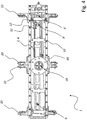
- Fig. 2 shows a schematic perspective view obliquely from below on a first embodiment of a gripping device according to the invention 1.
- the gripping device. 1 according to the embodiment Fig. 2 can after 100 for a system Fig. 1 Find use.
- the gripping device 1 has a suspension 10. With the suspension 10 are a first carriage 20 and a second carriage 22 via a respective linear guide 12 and 14 in conjunction. The first carriage 20 and the second carriage 22 can thus be moved along the suspension 10 or along the longitudinal extension of the suspension 10 with the aid of the respective linear guide 12 or 14. The suspension carries the first carriage 20 and the second carriage 22.
- the gripping device 1 additionally comprises a first gripping unit 7 and a second gripping unit 9 (cf. Figures 5 and 6 ), which for reasons of clarity in the FIGS. 2 to 4 not shown.
- Both the first gripping unit 7 and the second gripping unit 9 each have a first gripping means 15 and a second gripping means 17, which respective second gripping means 17 opposite the respective first gripping means 15 and cooperates with the respective first gripping means 15 for detecting cargo 5.
- the schematic perspective view of Fig. 2 indicates that the first carriage 20 has a predetermined position 11 for a first gripping means 15. At the predetermined position 11 thus a first gripping means 15 is arranged.
- the first carriage 20 has a first attachment position 6 and a second attachment position 8 for a further first gripping means 15.
- the further first gripping means 15 can thus be arranged selectively in the first attachment position 6 or in the second attachment position 8 on the first carriage 20.
- the first fastening position 6 or the second fastening position 8 can be calculated taking into account a relative distance between successive piece goods 5 or a pitch (cf. Fig. 1 ), after which the further first gripping means 15 is selectively fixed in the first fastening position 6 or in the second fastening position 8 on the first slide 20.
- FIG. 5 A synopsis of these figures shows the respective further first gripping means 15, which in Fig. 5 is fixed in the first attachment position 6 on the first carriage 20 and in Fig. 6 is set in the second attachment position 8 on the first carriage 20.
- the first gripping means 15 have in Figures 5 and 6 a different relative distance to each other, which is maintained upon detection and manipulation of a respective item 5 or container 3.
- the second carriage 22 has a predetermined position 13 for a second gripping means 17. At the predetermined position 13 thus a second gripping means 17 is fixed.
- the second carriage 22 also has a first attachment position 6 'and a second attachment position 8' for a further second gripping means 17.
- the further second gripping means 17 can selectively in the first attachment position 6 'or in the second attachment position 8' and possibly taking into account Division distance of successive cargo 5 on the second carriage 22 are arranged.
- a drive roller 60 and a guide roller 62 are also attached.
- a specific and formed as a belt 4 actuator 2 is guided circumferentially.
- a rotation axis of the drive roller 60 and a rotation axis of the deflection roller 62 are parallel to each other.
- Both the first carriage 20 and the second carriage 22 are mechanically coupled to the actuator 2 and the belt 4 so that the first carriage 20 and the second carriage 22 for performing a feed movement of their respective first and second gripping means 15 and 17 means of the actuator 2 or by means of the belt 4 can be moved.
- the drive roller 60 can be driven in rotation via an actuator, not shown, or via a handling device, not shown, and, as a result, the actuator 2 or the belt 4 move.
- the Fig. 3 shows a schematic view from below of the embodiment of a gripping device 1 from Fig. 2 ,
- Fig. 2 Again, the predetermined positions 11 and 13 of the first carriage 20 and the second carriage 22 for the respective first and second gripping means 15 and 17 can be seen.
- Fig. 2 recognize again the first attachment positions 6 and 6 'and the second attachment positions 8 and 8', to which the further first and second gripping means 15 and 17 can be fixed.
- the actuator 2 or the belt 4 extends parallel to the longitudinal axis of the suspension 10 and parallel to a direction of movement of the first carriage 20 and the second carriage 22nd
- Fig. 4 shows a schematic top view of the embodiment of a gripping device 1 from Figures 2 and 3 ,
- a flange portion 18 can be seen, to which an actuator or a handling device for rotating movement of the drive roller 60 (see. Fig. 2 ) can be coupled.
- paragraph 30 shows Fig. 4
- the actuator 2 and the belt 4 related clamping means via which the first carriage 20 on the actuator 2 or belt 4th is fixed.
- reference numeral 32 also clamping means are shown, via which the second carriage 22 on the actuator 2 or belt 4 is fixed.
- the clamping means 30, via which the first carriage 20 is fixed to the actuator 2 or belt 4 and the clamping means 32, via which the second carriage 22 is fixed to the actuator 2 or belt 4, are on opposite sides of the common actuator 2 and of the common belt 4 is positioned.
- the first carriage 20 and the second carriage 22 can be moved in a time-synchronized manner.
- the first gripping means 15 and the second gripping means 17 are moved synchronously in time as part of their advancing movement (cf. Fig. 5 ).
- the Fig. 5 shows a schematic side view of the embodiment of a gripping device 1 of the FIGS. 2 to 4 ,
- the two gripping units 7 and 9 can be seen, each comprising a first gripping means 15 and a second gripping means 17.
- a cargo 5 can be received by clamping and subsequently manipulated (see. Fig. 1 ).
- the respective first gripping means 15 of a respective gripping unit 7 or 9 is inclined in the direction of the opposite second gripping means 17 of a respective gripping unit 7 or 9.
- the respective second gripping means 17 of a respective gripping unit 7 or 9 is inclined in the direction of the opposite first gripping means 15 of a respective gripping unit 7 or 9.
- the first gripping means 15 are mechanically coupled with the first carriage 20.
- the second gripping means 17 are mechanically coupled to the second carriage 22.
- Fig. 5 it can be seen that the respective outer first or second gripping means 15 or 17 is fixed to the respective first fastening position 6 or 6 '.
- the Fig. 6 shows a further schematic side view of the embodiment of a gripping device 1 of the FIGS. 2 to 5 ,
- the components of the gripping device 1 off Fig. 6 are identical to the components of the gripping device 1 from Fig. 5 educated.
- Across from Fig. 5 is the respective outer first gripping means 15 and second gripping means 17 in the second mounting position 8 and 8 'on the respective carriage 20 and 22 respectively.
- a synopsis of Figures 5 and 6 illustrates here that the respective relative distance of the first gripping means 15 to their respective opposite second gripping means 17 in Fig. 6 across from Fig. 5 is less formed.
- the gripping device 1 Due to the different first attachment positions 6 and 6 'as well as the different second attachment positions 8 and 8' of the first carriage 20 and the second carriage 22 for the respective outer first gripping means 15 and second gripping means 17, the gripping device 1 at different pitches of successive piece goods 5 (see FIG. Fig. 1 ) be adjusted.
- the Fig. 7 shows individual steps, as they may be provided in a conceivable embodiment of the method according to the invention.
- a gripping device 1 according to the embodiment of FIGS. 1 to 6 Find use.
- a movement of a gripping device 1 together with at least two gripping units 7 and 9 in the direction of a plurality of piece goods 5 is provided.
- the first gripping means 15 of the at least two gripping units 7 and 9 are acted upon by a common mechanical coupling with a feed movement, as a result of the at least two gripping units 7 and 9 each own cargo 5 is detected by clamping and / or positive.
- the piece goods 5 are aligned over the gripping device 1 and / or positioned or manipulated.
Abstract
Es ist eine Greifvorrichtung (1) zum Erfassen mehrerer Stückgüter offenbart. Die Greifvorrichtung (1) umfasst mindestens zwei Greifeinheiten (7, 9), wobei die mindestens zwei Greifeinheiten (7, 9) jeweils ein erstes Greifmittel (15) und ein dem jeweiligen ersten Greifmittel (15) gegenüberliegendes zweites Greifmittel (17) besitzen, welches jeweilige erste Greifmittel (15) mit dem jeweiligen zweiten Greifmittel (17) zum klemmenden und/oder formschlüssigen Erfassen eines jeweiligen Stückgutes zusammenwirkt. Es ist vorgesehen, dass die ersten Greifmittel (15) der mindestens zwei Greifeinheiten (7, 9) und/oder die zweiten Greifmittel (17) der mindestens zwei Greifeinheiten (7, 9) für eine gemeinsame Zustellbewegung mechanisch miteinander bewegungsgekoppelt sind.It is a gripping device (1) for detecting multiple cargo disclosed. The gripping device (1) comprises at least two gripping units (7, 9), wherein the at least two gripping units (7, 9) each have a first gripping means (15) and a second gripping means (17) opposite the respective first gripping means (15) respective first gripping means (15) cooperates with the respective second gripping means (17) for the clamping and / or positive engagement of a respective piece goods. It is provided that the first gripping means (15) of the at least two gripping units (7, 9) and / or the second gripping means (17) of the at least two gripping units (7, 9) are mechanically coupled to one another for a common feed movement.
Description
Die vorliegende Erfindung betrifft eine Greifvorrichtung zum Erfassen mehrerer Stückgüter mit mindestens zwei Greifeinheiten, ein System zum Umgang mit mehreren Stückgütern und ein Verfahren zum Manipulieren mehrerer Stückgüter über eine Greifvorrichtung mit mindestens zwei Greifeinheiten.The present invention relates to a gripping device for detecting a plurality of packaged goods with at least two gripping units, a system for handling a plurality of packaged goods and a method for manipulating a plurality of packaged goods via a gripping device having at least two gripping units.
Bekannte Verpackungs- oder Palettieranlagen zum Stapeln und Palettieren von Objekten wie Paketen oder Gebinden mit mehreren Artikeln wie bspw. Getränkebehältern weisen üblicherweise Horizontalfördereinrichtungen mit Förderbändern auf, auf denen die Stückgüter oder Gebinde in ununterbrochener oder unregelmäßiger Folge und beabstandet zu einer Handhabungseinrichtung befördert werden. Dort erfolgt eine Verschiebung, Ausrichtung und/oder ein Drehen einzelner Stückgüter oder Gebinde, um diese in eine geeignete räumliche Anordnung zu bringen, die eine Basis bildet, um die Stückgüter oder Gebinde in nachgeordneten Gruppierstationen zu stapelfähigen Stückgut- oder Gebindelagen zusammenzuschieben.Known packaging or palletizing systems for stacking and palletizing objects such as packages or containers with several articles such as beverage containers usually have horizontal conveyors with conveyor belts on which the packages or packages are conveyed in an uninterrupted or irregular sequence and spaced to a handling device. There is a shift, alignment and / or turning individual piece goods or containers to bring them into a suitable spatial arrangement that forms a basis to push the piece goods or containers in subordinate Gruppierstationen to stackable cargo or bundle layers.
Bekannte Handhabungseinrichtungen, welche eine solche Verschiebung, Ausrichtung und/oder ein solches Drehen einzelner Stückgüter oder Gebinde bewirken, können auch mit Greifern versehen sein, die bspw. an einem Portalsystem aufgehängt und in einem definierten Bewegungsbereich verschoben, rotiert und zudem in vertikaler Richtung bewegt werden können, um einzelne Stückgüter oder Gebinde zum Drehen und/oder Verschieben anheben zu können. Die Greifer können in weiteren bekannten Ausführungsformen auch an Mehrachsroboterarmen angeordnet sein, die seitlich an den Horizontalfördereinrichtungen platziert sind. Derartige Greifvorrichtungen sind etwa aus der
Eine weitere solche Greifvorrichtung ist beispielsweise aus der
Die Praxis hat gezeigt, dass bei aufeinanderfolgenden Prozessen Artikel mit unterschiedlichen relativen Abständen bzw. Teilungsabständen zueinander in den Arbeitsbereich der Greifvorrichtung gelangen können. Bei bisher bekannten Handhabungseinrichtungen muss bis dato die vollständige Greifvorrichtung ausgetauscht werden, um unter Berücksichtigung des neuen relativen Abstandes Artikel gezielt erfassen zu können. Auch bei aufeinanderfolgenden Prozessen, bei welchen Artikel unterschiedliche Geometrien bzw. Dimensionierungen besitzen, ist eine Anpassung der jeweiligen Handhabungseinrichtung mit einem vollständigen Austausch der Greifvorrichtung verbunden.Practice has shown that in successive processes articles with different relative distances or pitches can reach each other in the work area of the gripping device. In hitherto known handling devices until now the complete gripping device has to be exchanged in order to be able to selectively detect articles taking into account the new relative distance. Even with successive processes, in which articles have different geometries or dimensions, an adaptation of the respective handling device is associated with a complete replacement of the gripping device.
Eine Aufgabe der Erfindung kann daher darin gesehen werden, eine gattungsgemäße Greifvorrichtung bzw. ein gattungsgemäßes System sowie Verfahren zur Verfügung zu stellen, welche eine hohe Flexibilität bei einer Zuführung von Artikeln mit unterschiedlichen relativen Abständen zueinander und/oder unterschiedlichen Geometrien besitzen. Die Greifvorrichtung und das System sollen einen unkomplizierten Aufbau besitzen. Weiterhin soll das Verfahren einfach umgesetzt werden können.An object of the invention can therefore be seen to provide a generic gripping device or a generic system and methods are available, which have a high flexibility in a supply of articles with different relative distances from each other and / or different geometries. The gripping device and the system should have a simple structure. Furthermore, the method should be easy to implement.
Diese Aufgaben werden durch eine Greifvorrichtung, ein System und ein Verfahren gelöst, welche die Merkmale in den Schutzansprüchen 1, 7 und 8 umfassen. Weitere vorteilhafte Ausgestaltungen werden durch die Unteransprüche beschrieben.These objects are achieved by a gripping device, a system and a method comprising the features in
Die Erfindung betrifft eine Greifvorrichtung zum Erfassen mehrerer Stückgüter. Die Stückgüter, welche mittels der Greifvorrichtung erfassbar sind, können beispielsweise durch Getränkebehältnisse bzw. durch mehrere zu einem Gebinde zusammengefasste Getränkebehältnisse ausgebildet sein.The invention relates to a gripping device for detecting a plurality of piece goods. The piece goods, which can be detected by means of the gripping device, can be formed for example by beverage containers or by a plurality of beverage containers combined into a container.
Die Greifvorrichtung umfasst mindestens zwei Greifeinheiten. Die mindestens zwei Greifeinheiten besitzen jeweils ein erstes Greifmittel und ein dem jeweiligen ersten Greifmittel gegenüberliegendes zweites Greifmittel, welches jeweilige erste Greifmittel mit dem jeweiligen zweiten Greifmittel zum klemmenden und/oder formschlüssigen Erfassen eines jeweiligen Stückgutes zusammenwirkt. In denkbaren Ausführungsformen kann die Greifvorrichtung auch mehr als zwei Greifeinheiten besitzen. Beispielsweise kann es sein, dass die Greifvorrichtung drei Greifeinheiten besitzt, die jeweils ein erstes Greifmittel und ein dem jeweiligen ersten Greifmittels gegenüberliegendes zweites Greifmittel besitzen, wobei ein erstes Greifmittel und ein dem jeweiligen ersten Greifmittel gegenüberliegendes zweites Greifmittels zum Erfassen eines jeweiligen Stückgutes zusammenwirken.The gripping device comprises at least two gripping units. The at least two gripping units each have a first gripping means and a second gripping means opposite to the respective first gripping means, which respective first gripping means cooperates with the respective second gripping means for clamping and / or form-locking gripping of a respective piece goods. In conceivable embodiments, the gripping device may also have more than two gripping units. For example, it may be that the gripping device has three gripping units each having a first gripping means and a second gripping means opposite the respective first gripping means, wherein a first gripping means and a respective second gripping means opposite the respective first gripping means for detecting a respective piece goods cooperate.
Die ersten Greifmittel und die zweiten Greifmittel können im Bereich ihres freien Endes einen Kontaktbereich für Stückgüter ausbilden. Bei klemmender und/oder formschlüssiger Erfassung eines jeweiligen Stückgutes kann das jeweilige Stückgut mit einem Kontaktbereich eines ersten Greifmittels und einem Kontaktbereich eines jeweiligen dem ersten Greifmittel gegenüberliegenden zweiten Greifmittels in Anlage geraten. Der jeweilige Kontaktbereich kann elastisch nachgiebig ausgebildet sein. Demnach kann mindestens ein erstes Greifmittel und/oder mindestens ein zweites Greifmittel im Kontaktbereich wenigstens eine durch Gummi oder weitere elastische nachgiebige Materialen ausgebildete Anlage aufweisen.The first gripping means and the second gripping means may form a contact area for piece goods in the region of their free end. In the case of clamping and / or form-locking detection of a respective piece good, the respective piece goods may come into contact with a contact region of a first gripping means and a contact region of a respective second gripping means opposite the first gripping means. The respective contact region may be formed elastically yielding. Accordingly, at least one first gripping means and / or at least one second gripping means in the contact region may have at least one abutment formed by rubber or other elastic compliant materials.
Um Stückgüter gezielt entgegennehmen zu können, haben sich Ausführungsformen bewährt, bei welchen die ersten Greifmittel und die zweiten Greifmittel in Richtung eines jeweiligen entgegenzunehmenden Stückgutes bzw. in Richtung des jeweiligen gegenüberliegenden Greifmittels geneigt orientiert sind.In order to be able to specifically receive piece goods, embodiments have proved successful in which the first gripping means and the second gripping means are oriented inclined in the direction of a respective piece goods to be picked or in the direction of the respective opposite gripping means.
Weiter ist vorgesehen, dass die ersten Greifmittel der mindestens zwei Greifeinheiten und/oder die zweiten Greifmittel der mindestens zwei Greifeinheiten für eine gemeinsame Zustellbewegung mechanisch miteinander bewegungsgekoppelt sind. Eine Bewegung eines ersten Greifmittels einer ersten Greifeinheit kann hierdurch mit einer zeitsynchronen Bewegung eines ersten Greifmittels einer zweiten Greifeinheit einhergehen. Die ersten Greifmittel können somit starr bzw. im Wesentlichen starr miteinander bewegungsgekoppelt sein. Ebenso können daher die zweiten Greifmittel starr bzw. im Wesentlichen starr miteinander bewegungsgekoppelt sein. Eine solche mechanische Bewegungskoppelung erlaubt eine hohe Flexibilität bei Entgegennahme bzw. Erfassung von Stückgütern in aufeinanderfolgenden Prozessen mit unterschiedlichen Teilungsabständen. Weiterhin können in aufeinanderfolgenden Prozessen Stückgüter mit unterschiedlichen Geometrien bzw. Dimensionierungen mittels der Greifvorrichtung ohne aufwendige Umrüstungsarbeiten einfach und unkompliziert entgegengenommen und ggf. manipuliert werden.It is further provided that the first gripping means of the at least two gripping units and / or the second gripping means of the at least two gripping units are mechanically coupled to one another for a common feed movement. A movement of a first gripping means of a first gripping unit can thereby be accompanied by a time-synchronous movement of a first gripping means of a second gripping unit. The first gripping means can thus be rigidly coupled or substantially rigidly coupled to one another. Likewise, therefore, the second gripping means may be rigidly coupled or substantially rigidly coupled with each other. Such a mechanical coupling of movement allows a high degree of flexibility in the acceptance or detection of piece goods in successive processes with different pitches. Furthermore, in successive processes, piece goods with different geometries or dimensions can be easily and simply accepted and possibly manipulated by means of the gripping device without costly conversion work.
Denkbar ist zudem, dass die Greifvorrichtung eine Aufhängung bzw. eine gemeinsame Aufhängung umfasst, an welcher die mindestens zwei Greifeinheiten verfahrbar angeordnet sind. Demnach können die mindestens zwei Greifeinheiten bzw. die ersten Greifmittel und/oder die zweiten Greifmittel der mindestens zwei Greifeinheiten bei ihrer jeweiligen Zustellbewegung relativ zur Aufhängung verfahren werden. Die mindestens zwei Greifeinheiten können somit von der Aufhängung bzw. von der gemeinsamen Aufhängung getragen werden. Über die Aufhängung kann die Greifvorrichtung ggf. mit einer nachfolgend noch beschriebenen Handhabungseinrichtung in Verbindung stehen. Die Aufhängung kann daher einen Flansch bzw. eine Koppelung für die nachfolgend noch beschriebene Handhabungseinrichtung bereitstellen. Bei Bewegung der Greifvorrichtung kann eine Längsachse der Aufhängung eine zumindest näherungsweise horizontale Orientierung besitzen.It is also conceivable that the gripping device comprises a suspension or a common suspension, on which the at least two gripping units are arranged to be movable. Accordingly, the at least two gripping units or the first gripping means and / or the second gripping means of the at least two gripping units be moved relative to the suspension at their respective feed movement. The at least two gripping units can thus be carried by the suspension or by the common suspension. About the suspension, the gripping device may optionally be in communication with a handling device described below. The suspension can therefore provide a flange or a coupling for the handling device described below. Upon movement of the gripping device, a longitudinal axis of the suspension may have an at least approximately horizontal orientation.
Weiter kann es sein, dass die ersten Greifmittel der mindestens zwei Greifeinheiten an einem gemeinsamen ersten Schlitten festgesetzt sind und/oder dass die zweiten Greifmittel der mindestens zwei Greifeinheiten an einem gemeinsamen zweiten Schlitten festgesetzt sind, welcher erste Schlitten und/oder welcher zweite Schlitten mit einer Linearführung in Verbindung stehen. Der erste Schlitten und der zweite Schlitten können daher ggf. unabhängig voneinander entlang der Linearführung bewegbar sein. Somit können der erste Schlitten und der zweite Schlitten entlang der Linearführung parallel zueinander und ggf. jeweils horizontal bewegbar sein. Eine Bewegungsrichtung des ersten Schlittens kann parallel bzw. fluchtend zu einer Bewegungsrichtung des zweiten Schlittens orientiert sein.It may also be that the first gripping means of the at least two gripping units are fixed to a common first carriage and / or that the second gripping means of the at least two gripping units are fixed to a common second carriage, which first carriage and / or which second carriage with a Linear guide in connection. The first carriage and the second carriage may therefore be independently movable along the linear guide, if necessary. Thus, the first carriage and the second carriage along the linear guide parallel to each other and, if appropriate, be moved horizontally. A direction of movement of the first carriage may be oriented parallel to a direction of movement of the second carriage.
Außerdem kann es sein, dass die Greifvorrichtung wenigstens ein insbesondere als Riemen ausgebildetes umlaufend geführtes Stellglied umfasst, an welches der erste Schlitten und/oder der zweite Schlitten für die jeweilige Zustellbewegung mechanisch gekoppelt sind. Das wenigstens eine umlaufend geführte Stellglied kann somit durch mindestens einen Riemen ausgebildet sein. Denkbar ist auch, dass das wenigstens eine umlaufend geführte Stellglied als Kettentrieb ausgebildet ist.In addition, it may be that the gripping device comprises at least one circumferentially guided in particular designed as a belt actuator, to which the first carriage and / or the second carriage are mechanically coupled for the respective feed movement. The at least one circumferentially guided actuator can thus be formed by at least one belt. It is also conceivable that the at least one circumferentially guided actuator is designed as a chain drive.
Weiter kann die Greifvorrichtung eine Umlenkrolle und eine Antriebsrolle umfassen, um welche das wenigstens eine Stellglied umlaufend geführt ist. Die Umlenkrolle kann eine Drehachse besitzen, die Antriebswelle eine Rotationsachse, wobei die Drehachse und die Rotationsachse parallel zueinander orientiert sind.Further, the gripping device may comprise a deflection roller and a drive roller, around which the at least one actuator is guided circumferentially. The deflection roller may have an axis of rotation, the drive shaft an axis of rotation, wherein the axis of rotation and the axis of rotation are oriented parallel to each other.
Die Antriebsrolle kann mit einem Aktor in Verbindung stehen bzw. von der nachfolgend noch beschriebenen Handhabungseinrichtung rotierend angetrieben werden. Ein Aktor der Handhabungseinrichtung kann die Antriebsrolle für eine Zustellbewegung der ersten Greifmittel und/oder der zweiten Greifmittel hierzu rotierend bewegen. Die Umlenkrolle und/oder die Antriebsrolle können an der bereits erwähnten Aufhängung befestigt bzw. gelagert sein. Der wenigstens eine Aktor kann mindestens einen Servomotor zum Antrieb des wenigstens einen Stellgliedes bzw. zum Rotieren der Antriebsrolle umfassen. Ebenso kann der Aktor bzw. der Servomotor auf der Aufhängung aufsitzen bzw. an der Aufhängung festgesetzt sein. Das wenigstens eine umlaufend geführte Stellglied bzw. der wenigstens eine Riemen kann parallel zur Längserstreckung der Aufhängung und/oder parallel zu einer Bewegungsrichtung des ersten Schlittens und/oder des zweiten Schlittens verlaufen. Demnach kann sich das wenigstens eine Stellglied bzw. der wenigstens eine Riemen parallel zur Führungsrichtung der Linearführung erstrecken.The drive roller can be connected to an actuator or driven in rotation by the handling device described below. An actuator of the handling device can rotate the drive roller for a feed movement of the first gripping means and / or the second gripping means for this purpose. The deflection roller and / or the drive roller can on the suspension already mentioned be attached or stored. The at least one actuator may comprise at least one servomotor for driving the at least one actuator or for rotating the drive roller. Likewise, the actuator or the servo motor can be seated on the suspension or fixed to the suspension. The at least one circumferentially guided actuator or the at least one belt can run parallel to the longitudinal extent of the suspension and / or parallel to a direction of movement of the first carriage and / or the second carriage. Accordingly, the at least one actuator or the at least one belt may extend parallel to the guide direction of the linear guide.
Zudem ist vorstellbar, dass die Greifvorrichtung ein bestimmtes insbesondere als Riemen ausgebildetes umlaufend geführtes Stellglied umfasst, an welches sowohl der erste Schlitten als auch der zweite Schlitten für die jeweilige Zustellbewegung jeweils mechanisch gekoppelt sind. Auch hierbei kann es sein, dass die Greifvorrichtung eine Umlenkrolle und eine Antriebsrolle umfasst, um welche das wenigstens eine bestimmte Stellglied bzw. der bestimmte Riemen umlaufend geführt ist. Die Antriebsrolle kann, wie vorhergehend bereits beschrieben, weiterhin mit einem Aktor in Verbindung stehen bzw. einen Flansch zur Verbindung mit einem Aktor bzw. zur Verbindung mit einer Handhabungseinrichtung bereitstellen. Der erste Schlitten und der zweite Schlitten können über das bestimmte insbesondere als Riemen ausgebildete umlaufend geführte Stellglied miteinander bewegungsgekoppelt sein. Insbesondere kann für den ersten Schlitten eine Klemmverbindung vorgesehen sein, mittels welcher der erste Schlitten an das bestimmte insbesondere als Riemen ausgebildete umlaufend geführte Stellglied gekoppelt ist. Auch kann für den zweiten Schlitten eine Klemmverbindung vorgesehen sein, mittels welcher der zweite Schlitten an das bestimmte insbesondere als Riemen ausgebildete umlaufend geführte Stellglied gekoppelt ist. Der erste Schlitten und der zweite Schlitten können insbesondere mittels einer jeweiligen Klemmverbindung auf gegenüberliegenden Seiten an das bestimmte insbesondere als Riemen ausgebildete umlaufend geführte Stellglied mechanisch gekoppelt sein.In addition, it is conceivable that the gripping device comprises a specific, in particular designed as a belt circumferentially guided actuator, to which both the first carriage and the second carriage for the respective feed movement are each mechanically coupled. In this case, too, it may be that the gripping device comprises a deflection roller and a drive roller, around which the at least one specific actuator or the specific belt is guided circumferentially. The drive roller may, as previously described, continue to communicate with an actuator or provide a flange for connection to an actuator or for connection to a handling device. The first carriage and the second carriage may be coupled to each other in motion via the particular rotatably guided actuator designed in particular as a belt. In particular, a clamping connection can be provided for the first carriage, by means of which the first carriage is coupled to the specific, in particular designed as a belt circumferentially guided actuator. Also, for the second carriage, a clamping connection can be provided, by means of which the second carriage is coupled to the particular designed in particular as a belt circumferentially guided actuator. The first slide and the second slide can be mechanically coupled in particular by means of a respective clamping connection on opposite sides of the particular designed in particular as a belt circumferentially guided actuator.
Ausführungsformen mit einem bestimmten Stellglied, an welches sowohl der erste Schlitten als auch der zweite Schlitten für die jeweilige Zustellbewegung mechanisch gekoppelt sind, haben sich bewährt, um auf einfache und unkomplizierte Art und Weise und mit geringem konstruktiven Aufwand eine Zustellbewegung für erste und zweite Greifmittel mindestens zweier Greifeinheiten zu ermöglichen. Das bestimmte Stellglied bzw. der bestimmte Riemen kann sich zu weniger als zwei Drittel entlang der Längserstreckung der Aufhängung erstrecken. Werden die ersten Greifmittel und die zweiten Greifmittel der mindestens zwei Greifeinheiten zugestellt, so können der erste Schlitten und der zweite Schlitten in Richtung zueinander verfahren werden.Embodiments with a specific actuator, to which both the first carriage and the second carriage are mechanically coupled for the respective feed movement, have proven to be in a simple and straightforward manner and with little design effort, a feed movement for first and second gripping means at least allow two gripping units. The particular actuator or belt may extend to less than two-thirds along the length of the suspension. Are the first gripping means and the second gripping means delivered to the at least two gripping units, the first carriage and the second carriage can be moved in the direction of each other.
Zudem kann vorgesehen sein, dass die ersten Greifmittel des ersten Schlittens selektiv in wenigstens zwei unterschiedlichen relativen Beabstandungen zueinander am ersten Schlitten festsetzbar sind und/oder dass die zweiten Greifmittel des zweiten Schlittens selektiv in wenigstens zwei unterschiedlichen relativen Beabstandungen zueinander am zweiten Schlitten festsetzbar sind. Somit kann wenigstens ein erstes Greifmittel und/oder wenigstens ein zweites Greifmittel abnehmbar am jeweiligen Schlitten festgesetzt sein. Beispielsweise kann die Greifvorrichtung Rast- und/oder Schnapp- und/oder Klemmverbindungen umfassen, um das wenigstens eine erste Greifmittel und/oder das wenigstens eine zweite Greifmittel abnehmbar und in der jeweiligen relativen Beabstandung zum weiteren ersten bzw. zweiten Greifmittel abnehmbar am jeweiligen Schlitten festzusetzen. Der erste Schlitten und/oder der zweite Schlitten können ggf. mehrere bestimmte Positionen bereitstellen, um die ersten Greifmittel bzw. die zweiten Greifmittel in einer gewünschten jeweiligen relativen Beabstandung zueinander am jeweiligen ersten Schlitten bzw. zweiten Schlitten festzusetzen.In addition, it can be provided that the first gripping means of the first carriage are selectively fixable in at least two different relative distances to each other on the first carriage and / or that the second gripping means of the second carriage are selectively fixable in at least two different relative spacings to each other on the second carriage. Thus, at least one first gripping means and / or at least one second gripping means can be detachably fixed to the respective slide. For example, the gripping device can comprise detent and / or snap and / or clamping connections in order to detachably fix the at least one first gripping means and / or the at least one second gripping means to the respective slide in the respective relative spacing to the further first and second gripping means , Optionally, the first carriage and / or the second carriage may provide a plurality of predetermined positions to fix the first gripping means and the second gripping means, respectively, in a desired relative spaced relation to each other on the respective first carriage and second carriage, respectively.
Die Erfindung betrifft darüber hinaus ein System zum Umgang mit Stückgütern. Das System umfasst eine Handhabungseinrichtung mit einer Greifvorrichtung gemäß vorheriger Beschreibung. Weiter umfasst das System mindestens eine Transporteinrichtung, mittels welcher eine Vielzahl an Stückgütern einem Arbeitsbereich der Handhabungseinrichtung zuführbar sind und aus dem Arbeitsbereich der Handhabungseinrichtung bewegbar sind. Auch umfasst das System eine Steuerungseinheit, über welche die Handhabungseinrichtung zum Erfassen und Manipulieren von Stückgütern unter Zuhilfenahme ihrer Greifvorrichtung ansteuerbar ist.The invention also relates to a system for handling general cargo. The system comprises a handling device with a gripping device as described above. Furthermore, the system comprises at least one transport device by means of which a multiplicity of piece goods can be fed to a working area of the handling device and can be moved out of the working area of the handling device. The system also includes a control unit, via which the handling device for detecting and manipulating piece goods with the aid of its gripping device can be controlled.
Insbesondere kann es sein, dass die Handhabungseinrichtung hierbei als Deltakinematik-Roboter ausgebildet ist. Darüber hinaus kann für weitere Ausführungsformen vorgesehen sein, dass die Handhabungseinrichtung als Mehrachsroboter ausgebildet ist. Auch ist vorstellbar, dass die Handhabungseinrichtung als Portalsystem ausgebildet ist, mittels dessen die Greifvorrichtung zum Manipulieren von Stückgütern verfahren werden kann. In denkbaren Ausführungsformen kann das System eine Handhabungseinrichtung umfassen. Vorstellbar ist jedoch auch, dass das System mehrere Handhabungseinrichtungen mit einer jeweiligen Greifvorrichtung und/oder eine Handhabungseinrichtung mit mehreren Greifvorrichtungen umfasst, wobei die mehreren Handhabungseinrichtungen bzw. die mehreren Greifvorrichtungen zum Manipulieren von Stückgütern zusammenwirken bzw. miteinander in Wirkverbindung stehen. Das System kann als Dreh- und Verteilsystem für Stückgüter ausgebildet sein. Weiter kann es sein, dass das System zum Herstellen einer palettierfähigen Lage aus einer Vielzahl an Stückgütern oder zum Herstellen einer Vorgruppierung für eine palettierfähige Lage aus einer Vielzahl an Stückgütern ausgebildet ist.In particular, it may be that the handling device is designed here as a delta kinematics robot. In addition, it can be provided for further embodiments that the handling device is designed as a multi-axis robot. It is also conceivable that the handling device is designed as a portal system, by means of which the gripping device can be moved for manipulating piece goods. In conceivable embodiments, the system may include a handling device. However, it is also conceivable that the system comprises a plurality of handling devices with a respective gripping device and / or a handling device with a plurality of gripping devices, wherein the plurality of handling devices or the plurality of gripping devices for Manipulating piece goods interact or are in operative connection with each other. The system can be designed as a turning and distribution system for piece goods. It may also be that the system is designed to produce a palletizable layer from a plurality of piece goods or to produce a pre-grouping for a palletizable layer from a plurality of piece goods.
Die Erfindung betrifft darüber hinaus ein Verfahren zum Manipulieren mehrerer Stückgüter über eine Greifvorrichtung mit mindestens zwei Greifeinheiten. Merkmale, welche vorhergehend bereits zur Greifvorrichtung bzw. zum System beschrieben wurden, können ebenso bei nachfolgend beschriebenem Verfahren vorgesehen sein und werden daher nicht redundant erwähnt. Zudem können nachfolgend beschriebene Merkmale, welche das Verfahren betreffen, für diverse Ausführungsformen der Greifvorrichtung bzw. des Systems vorgesehen sein.The invention further relates to a method for manipulating a plurality of piece goods via a gripping device with at least two gripping units. Features which have already been described above for the gripping device or the system can also be provided in the method described below and are therefore not mentioned redundantly. In addition, features described below, which relate to the method, may be provided for various embodiments of the gripping device or the system.
Auch im Rahmen des erfindungsgemäßen Verfahrens umfassen die mindestens zwei Greifeinheiten jeweils ein erste Greifmittel und jeweils ein dem jeweiligen ersten Greifmittel gegenüberliegendes zweites Greifmittel. Das Verfahren umfasst folgende Schritte:
- Bewegen der Greifvorrichtung zusammen mit den mindestens zwei Greifeinheiten in Richtung mehrerer Stückgüter,
- klemmendes und/oder formschlüssiges Erfassen jeweils wenigstens eines eigenen Stückgutes durch die mindestens zwei Greifeinheiten,
- Ausrichten und/oder Positionieren der Stückgüter über die Greifvorrichtung zeitlich nach ihrer klemmenden und/oder formschlüssigen Erfassung.
- Moving the gripping device together with the at least two gripping units in the direction of several piece goods,
- clamping and / or form-locking detection of at least one individual piece good by the at least two gripping units,
- Aligning and / or positioning the piece goods via the gripping device temporally after their clamping and / or positive detection.
Zudem ist vorgesehen, dass
- die ersten Greifmittel über eine gemeinsame erste mechanische Koppelung mit einer Zustellbewegung beaufschlagt werden, woraus resultierend die eigenen Stückgüter durch die mindestens zwei Greifeinheiten klemmend und/oder formschlüssig erfasst werden und/oder dass
- die zweiten Greifmittel über eine gemeinsame zweite mechanische Koppelung mit einer Zustellbewegung beaufschlagt werden, woraus resultierend die eigenen Stückgüter durch die mindestens zwei Greifeinheiten klemmend und/oder formschlüssig erfasst werden.
- the first gripping means are acted upon by a common first mechanical coupling with a feed movement, as a result of which the own piece goods are gripped by the at least two gripping units in a clamping and / or form-fitting manner and / or
- the second gripping means are acted upon by a common second mechanical coupling with a feed movement, as a result of which the own piece goods are clamped and / or positively detected by the at least two gripping units.
In der Praxis haben sich insbesondere Ausführungsformen bewährt, bei welchen die erste mechanische Koppelung einen ersten Schlitten umfasst und bei welchen die zweite mechanische Koppelung einen zweiten Schlitten umfasst, wobei der erste Schlitten und/oder der zweite Schlitten zum bzw. bei Ausführen der jeweiligen Zustellbewegung entlang wenigstens einer Linearführung bewegt werden. Der erste Schlitten und der zweite Schlitten können hierbei parallel zueinander bewegt bzw. verfahren werden.In practice, in particular embodiments have proven in which the first mechanical coupling comprises a first carriage and in which the second mechanical coupling comprises a second carriage, wherein the first carriage and / or the second carriage for or during execution of the respective feed movement along be moved at least one linear guide. The first carriage and the second carriage can be moved or moved parallel to each other.
Weiter kann es sein, dass der erste Schlitten und/oder der zweite Schlitten an wenigstens einem vorzugsweise als Riemen ausgebildeten umlaufend geführten Stellglied befestigt sind, wobei der erste Schlitten und/oder der zweite Schlitten zum Ausführen der jeweiligen Zustellbewegung über das wenigstens eine Stellglied entlang der wenigstens einen Linearführung bewegt werden. Insbesondere können der erste Schlitten und der zweite Schlitten an einem gemeinsamen bestimmten vorzugsweise als Riemen ausgebildeten umlaufend geführten Stellglied befestigt sein. Das vorzugsweise als Riemen ausgebildete umlaufend geführte bestimmte Stellglied kann angetrieben werden, woraus resultierend die ersten Greifmittel und die zweiten Greifmittel zeitsynchron eine Zustellbewegung einleiten. Zum Beenden der Zustellbewegung der ersten Greifmittel und der zweiten Greifmittel kann das vorzugsweise als Riemen ausgebildete umlaufend geführte bestimmte Stellglied angehalten werden. Insbesondere kann das vorzugweise als Riemen ausgebildete umlaufend geführte bestimmte Stellglied aktorisch angetrieben werden.Furthermore, it may be that the first carriage and / or the second carriage are fastened to at least one circumferentially guided actuator, preferably designed as a belt, wherein the first carriage and / or the second carriage can be moved via the at least one actuator along the be moved at least one linear guide. In particular, the first carriage and the second carriage may be fastened to a common certain, preferably belt-shaped, rotatably guided actuator. The trained as a belt circumferentially guided certain actuator can be driven, resulting in the first gripping means and the second gripping means time synchronously initiate a feed movement. To terminate the feed movement of the first gripping means and the second gripping means, the preferably designed as a belt circumferentially guided certain actuator can be stopped. In particular, the preferably designed as a belt circumferentially guided certain actuator can be actuated actuated.
Denkbar ist zudem, dass zeitlich vor Bewegen der Greifvorrichtung zusammen mit den mindestens zwei Greifeinheiten in Richtung der mehreren Stückgüter
- eine bestimmte relative Beabstandung aus wenigstens zwei relativen Beabstandungen für die ersten Greifmittel ausgewählt und die ersten Greifmittel in der bestimmten ausgewählten relativen Beabstandung am ersten Schlitten festgesetzt werden, welche bestimmte relative Beabstandung die ersten Greifmittel während des klemmenden und/oder formschlüssigen Erfassens und während des Ausrichtens und Positionierens der Stückgüter beibehalten und/oder bei welchem zeitlich vor Bewegen der Greifvorrichtung zusammen mit den mindestens zwei Greifeinheiten in Richtung der mehreren Stückgüter
- eine bestimmte relative Beabstandung aus wenigstens zwei relativen Beabstandungen für die zweiten Greifmittel ausgewählt und die zweiten Greifmittel in der bestimmten ausgewählten relativen Beabstandung am zweiten Schlitten festgesetzt werden, welche bestimmte relative Beabstandung die zweiten Greifmittel während des klemmenden und/oder formschlüssigen Erfassens und während des Ausrichtens und Positionierens der Stückgüter beibehalten.
- a certain relative spacing is selected from at least two relative spacings for the first gripping means and the first gripping means is set at the particular selected relative spacing on the first slide, which particular relative spacing the first gripping means during clamping and / or positive engagement and during alignment and Maintaining positioning of the piece goods and / or at which time before moving the gripping device together with the at least two gripping units in the direction of the multiple piece goods
- a certain relative spacing selected from at least two relative spacings for the second gripping means and the second gripping means in the particular selected relative spacing on the second carriage are fixed, which certain relative spacing the second gripping means during the clamping and / or positive detection and during the alignment and positioning of the piece goods maintained.
In der Praxis haben sich zudem Ausführungsformen bewährt, bei welchen der erste Schlitten und der zweite Schlitten beim Ausführen der Zustellbewegung zeitsynchron bewegt werden. Wie vorhergehend bereits erwähnt, kann hierzu eine Bewegung des ersten Schlittens zumindest näherungsweise zeitgleich mit einer Bewegung des zweiten Schlittens beginnen. Weiter kann eine Bewegung des ersten Schlittens zumindest näherungsweise zeitgleich mit einer Bewegung des zweiten Schlittens enden.In practice, moreover, embodiments have proved successful in which the first carriage and the second carriage are moved in synchronism with the execution of the feed movement. As already mentioned above, for this purpose, a movement of the first carriage can begin at least approximately simultaneously with a movement of the second carriage. Furthermore, a movement of the first carriage may end at least approximately simultaneously with a movement of the second carriage.
Im Folgenden sollen Ausführungsbeispiele die Erfindung und ihre Vorteile anhand der beigefügten Figuren näher erläutern. Die Größenverhältnisse der einzelnen Elemente zueinander in den Figuren entsprechen nicht immer den realen Größenverhältnissen, da einige Formen vereinfacht und andere Formen zur besseren Veranschaulichung vergrößert im Verhältnis zu anderen Elementen dargestellt sind.
-
Fig. 1 zeigt eine schematische Ansicht einer denkbaren Ausführungsform für das erfindungsgemäße System; -
Fig. 2 zeigt eine schematische Perspektivansicht von schräg unten auf eine erste Ausführungsform einer erfindungsgemäßen Greifvorrichtung; -
Fig. 3 zeigt eine schematische Ansicht von unten auf die Ausführungsform einer Greifvorrichtung ausFig. 2 ; -
Fig. 4 zeigt eine schematische Ansicht von oben auf die Ausführungsform einer Greifvorrichtung ausFiguren 2 und3 ; -
Fig. 5 zeigt eine schematische Seitenansicht auf die Ausführungsform einer Greifvorrichtung aus denFiguren 2 bis 4 ; -
Fig. 6 zeigt eine weitere schematische Seitenansicht auf die Ausführungsform einer Greifvorrichtung aus denFiguren 2 bis 5 ; -
Fig. 7 zeigt einzelne Schritte, wie sie bei einer denkbaren Ausführungsform des erfindungsgemäßen Verfahrens vorgesehen sein können.
-
Fig. 1 shows a schematic view of a conceivable embodiment of the system according to the invention; -
Fig. 2 shows a schematic perspective view obliquely from below of a first embodiment of a gripping device according to the invention; -
Fig. 3 shows a schematic view from below of the embodiment of a gripping deviceFig. 2 ; -
Fig. 4 shows a schematic view from above of the embodiment of a gripping deviceFigures 2 and3 ; -
Fig. 5 shows a schematic side view of the embodiment of a gripping device from theFIGS. 2 to 4 ; -
Fig. 6 shows a further schematic side view of the embodiment of a gripping device from theFIGS. 2 to 5 ; -
Fig. 7 shows individual steps, as they may be provided in a conceivable embodiment of the method according to the invention.
Für gleiche oder gleich wirkende Elemente der Erfindung werden identische Bezugszeichen verwendet. Ferner werden der Übersicht halber nur Bezugszeichen in den einzelnen Figuren dargestellt, die für die Beschreibung der jeweiligen Figur erforderlich sind. Die dargestellten Ausführungsformen stellen lediglich Beispiele dar, wie die Erfindung ausgestaltet sein kann und stellen keine abschließende Begrenzung dar.For identical or equivalent elements of the invention, identical reference numerals are used. Furthermore, for the sake of clarity, only reference symbols are shown in the individual figures, which are required for the description of the respective figure. The illustrated embodiments are merely examples of how the invention may be configured and are not an exhaustive limitation.
Die
Über die Horizontalfördereinrichtung 52 des Einteilers 50 werden die ausgerichteten bzw. eingeteilten Stückgüter 5 sodann einem Manipulationsbereich 70 zugeführt, welcher dem Einteiler 50 in Transportrichtung der Stückgüter 5 bzw. Gebinde 3 unmittelbar nachgeordnet ist.The aligned or divided piece goods 5 are then fed to a
Der Manipulationsbereich 70 verfügt über zwei Greifvorrichtungen 1, die als Bestandteil einer jeweiligen in
Da aufeinanderfolgende Stückgüter 5, welche in den Manipulationsbereich 70 übergetreten sind, mittels der Greifeinheiten 7 und 9 einer jeweiligen Greifvorrichtung 1 erfasst und hierauf folgend manipuliert werden, müssen die Relativpositionen der Greifeinheiten 7 und 9 bzw. der ersten Greifmittel 15 und der zweiten Greifmittel 17 an die Beabstandungen aufeinanderfolgender Stückgüter 5 angepasst sein, um aufeinanderfolgende Stückgüter 5 mittels der Greifeinheiten 7 und 9 entgegennehmen zu können. In der Praxis wurden hierzu bisher die Greifvorrichtungen 1 ausgetauscht, um einen gezielte Erfassung von mittels des Einteilers 50 relativ zueinander beabstandeten aufeinanderfolgenden Stückgütern 5 gewährleisten zu können. Die Erfindung ermöglicht eine Anpassung der Greifvorrichtung 1 an unterschiedliche Abstände aufeinanderfolgender Stückgüter 5 bzw. Teilungsabstände aufeinanderfolgender Stückgüter 5 ohne vollständigen Austausch der Greifvorrichtungen 1. Auch können mittels der erfindungsgemäßen Greifvorrichtung 1 Stückgüter 5 mit unterschiedlichen Geometrien unter unkomplizierter Anpassung der Greifvorrichtung 1 an die jeweilige Geometrie gezielt erfasst und manipuliert werden.Since successive piece goods 5, which have entered the
Die
Die Handhabungseinrichtungen, welche die Greifvorrichtungen 1 zum Versetzen bzw. Verteilen der Stückgüter 5 bzw. Gebinde 3 bewegen, stehen mit einer Steuerungseinheit S in Verbindung. Die Steuerungseinheit S bewirkt eine aufeinander abgestimmte Bewegung beider Greifvorrichtungen 1 bzw. beider Handhabungseinrichtungen, deren Bestandteil die Greifvorrichtungen 1 sind, so dass beide Greifvorrichtungen 1 selektiv Stückgüter 5 bzw. Gebinde 3 entgegennehmen und aufeinander abgestimmt an die einzelnen zwischen jeweils unmittelbar benachbarten Führungsgeländern 81 ausgebildeten Gassen verteilen können.The handling devices, which move the
Die Greifvorrichtung 1 ist in
Die Greifvorrichtung 1 besitzt eine Aufhängung 10. Mit der Aufhängung 10 stehen ein erster Schlitten 20 und ein zweiter Schlitten 22 über eine jeweilige Linearführung 12 bzw. 14 in Verbindung. Der erste Schlitten 20 und der zweite Schlitten 22 können somit unter Zuhilfenahme der jeweiligen Linearführung 12 bzw. 14 entlang der Aufhängung 10 bzw. entlang der Längserstreckung der Aufhängung 10 verfahren werden. Die Aufhängung trägt den ersten Schlitten 20 und den zweiten Schlitten 22.The
Die Greifvorrichtung 1 umfasst zudem eine erste Greifeinheit 7 und eine zweite Greifeinheit 9 (vgl.
Die schematische Perspektivansicht der
Weiter besitzt der zweite Schlitten 22 eine vorgegebene Position 13 für ein zweites Greifmittel 17. An der vorgegebenen Position 13 wird somit ein zweites Greifmittel 17 festgesetzt. Auch der zweite Schlitten 22 besitzt eine erste Befestigungsposition 6' und eine zweite Befestigungsposition 8' für ein weiteres zweites Greifmittel 17. Das weitere zweite Greifmittel 17 kann selektiv in der ersten Befestigungsposition 6' oder in der zweiten Befestigungsposition 8' und ggf. unter Berücksichtigung eines Teilungsabstandes aufeinanderfolgender Stückgüter 5 am zweiten Schlitten 22 angeordnet werden.Next, the
An der Aufhängung 10 sind zudem eine Antriebsrolle 60 und eine Umlenkrolle 62 befestigt. Mittels der Antriebsrolle 60 und der Umlenkrolle 62 ist ein bestimmtes und als Riemen 4 ausgebildetes Stellglied 2 umlaufend geführt. Eine Rotationsachse der Antriebsrolle 60 und eine Drehachse der Umlenkrolle 62 verlaufen parallel zueinander. Sowohl der erste Schlitten 20 als auch der zweite Schlitten 22 sind mechanisch an das Stellglied 2 bzw. den Riemen 4 gekoppelt, so dass der erste Schlitten 20 und der zweite Schlitten 22 zum Durchführen einer Zustellbewegung ihrer jeweiligen ersten bzw. zweiten Greifmittel 15 und 17 mittels des Stellglied 2 bzw. mittels des Riemens 4 verfahren werden können. Die Antriebsrolle 60 kann über einen nicht dargestellten Aktor bzw. über eine nicht dargestellte Handhabungseinrichtung rotierend angetrieben werden und hieraus resultierend das Stellglied 2 bzw. den Riemen 4 bewegen.On the
Die
Die
Die
Die
Die
Für einen ersten Schritt des Verfahrens ist ein Bewegen einer Greifvorrichtung 1 zusammen mit mindestens zwei Greifeinheiten 7 und 9 in Richtung mehrerer Stückgüter 5 vorgesehen. Anschließend werden die ersten Greifmittel 15 der mindestens zwei Greifeinheiten 7 und 9 über eine gemeinsame mechanische Koppelung mit einer Zustellbewegung beaufschlagt, woraus resultierend über die mindestens zwei Greifeinheiten 7 und 9 jeweils ein eigenes Stückgut 5 klemmend und/oder formschlüssig erfasst wird. Nach ihrer klemmenden und/oder formschlüssigen Erfassung werden die Stückgüter 5 über die Greifvorrichtung 1 ausgerichtet und/oder positioniert bzw. manipuliert.For a first step of the method, a movement of a
Die Erfindung wurde unter Bezugnahme auf eine bevorzugte Ausführungsform beschrieben. Es ist jedoch für einen Fachmann vorstellbar, dass Abwandlungen oder Änderungen der Erfindung gemacht werden können, ohne dabei den Schutzbereich der nachstehenden Ansprüche zu verlassen.The invention has been described with reference to a preferred embodiment. However, it will be apparent to those skilled in the art that modifications or changes may be made to the invention without departing from the scope of the following claims.
- 11
- Greifvorrichtunggripping device
- 22
- Stellgliedactuator
- 33
- Gebindecontainer
- 44
- Riemenbelt
- 55
- Stückgutcargo
- 66
- Erste Befestigungsposition (Erster Schlitten (20))First mounting position (first carriage (20))
- 6'6 '
- Erste Befestigungsposition (Zweiter Schlitten (22))First mounting position (second carriage (22))
- 77
- Erste GreifeinheitFirst gripping unit
- 88th
- Zweite Befestigungsposition (Erster Schlitten (20))Second mounting position (first slide (20))
- 8'8th'
- Zweite Befestigungsposition (Zweiter Schlitten (22))Second mounting position (second carriage (22))
- 99
- Zweite GreifeinheitSecond gripping unit
- 1010
- Aufhängungsuspension
- 1111
- Vorgegebene Position (Erstes Greifmittel 15)Predetermined position (first gripping means 15)
- 1212
- Linearführung (Erster Schlitten)Linear guide (first slide)
- 1313
- Vorgegebene Position (Zweites Greifmittel 17)Predetermined position (second gripping means 17)
- 1414
- Linearführung (Zweiter Schlitten)Linear guide (second slide)
- 1515
- Erstes GreifmittelFirst gripping means
- 1717
- Zweites GreifmittelSecond gripping means
- 1818
- Flanschabschnittflange
- 2020
- Erster SchlittenFirst sled
- 2222
- Zweiter SchlittenSecond sled
- 3030
- Klemmittel (Erster Schlitten 20)Clamping means (first slide 20)
- 3232
- Klemmittel (Zweiter Schlitten 22)Clamping means (second slide 22)
- 5050
- Einteilerone piece
- 5151
- Schubbalkenthrust bar
- 5252
- HorizontalfördereinrichtungHorizontal conveyor
- 6060
- Antriebsrollecapstan
- 6262
- Umlenkrolleidler pulley
- 7070
- Manipulationsbereichmanipulation region
- 8080
- Auslaufoutlet
- 8181
- Führungsgeländerguide railings
- 100100
- Systemsystem
- 110110
- Verteilsystemdistribution system
- SS
- Steuerungseinheitcontrol unit
Claims (13)
Priority Applications (1)
| Application Number | Priority Date | Filing Date | Title |
|---|---|---|---|
| SI201731012T SI3260399T1 (en) | 2016-06-22 | 2017-06-12 | Gripper device for the grasping of a plurality of articles, handling system with multiple piece goods and method for manipulating a plurality of piece goods |
Applications Claiming Priority (1)
| Application Number | Priority Date | Filing Date | Title |
|---|---|---|---|
| DE102016211187.6A DE102016211187A1 (en) | 2016-06-22 | 2016-06-22 | Gripping device for detecting several piece goods, system for handling several piece goods and method for manipulating several piece goods |
Publications (2)
| Publication Number | Publication Date |
|---|---|
| EP3260399A1 true EP3260399A1 (en) | 2017-12-27 |
| EP3260399B1 EP3260399B1 (en) | 2021-09-22 |
Family
ID=59034657
Family Applications (1)
| Application Number | Title | Priority Date | Filing Date |
|---|---|---|---|
| EP17175487.2A Active EP3260399B1 (en) | 2016-06-22 | 2017-06-12 | Gripper device for the grasping of a plurality of articles, handling system with multiple piece goods and method for manipulating a plurality of piece goods |
Country Status (4)
| Country | Link |
|---|---|
| EP (1) | EP3260399B1 (en) |
| CN (1) | CN206955190U (en) |
| DE (1) | DE102016211187A1 (en) |
| SI (1) | SI3260399T1 (en) |
Cited By (3)
| Publication number | Priority date | Publication date | Assignee | Title |
|---|---|---|---|---|
| CN112867587A (en) * | 2018-09-26 | 2021-05-28 | 费斯托股份两合公司 | Manipulator for repositioning an object |
| CN114658198A (en) * | 2020-12-22 | 2022-06-24 | 广东博智林机器人有限公司 | Grabbing device, wallboard mounting equipment and wallboard grabbing control method |
| CN117226879A (en) * | 2023-11-10 | 2023-12-15 | 中机真空科技(济南)有限公司 | Manipulator grabbing mechanism |
Families Citing this family (2)
| Publication number | Priority date | Publication date | Assignee | Title |
|---|---|---|---|---|
| CN109230321B (en) | 2018-10-12 | 2020-07-21 | 上海大族富创得科技有限公司 | Material conveying system, conveying method and storage device |
| IT201900022404A1 (en) * | 2019-11-28 | 2021-05-28 | Ct Pack Srl | ARTICLE TRANSFER SYSTEM FOR PACKAGING MACHINE, PACKAGING MACHINE, PROCEDURE AND CORRESPONDING IT PRODUCT. |
Citations (5)
| Publication number | Priority date | Publication date | Assignee | Title |
|---|---|---|---|---|
| DE1214368B (en) * | 1962-06-26 | 1966-04-14 | Keller & Co C | Gripper for picking up objects, in particular ceramic moldings, arranged at a distance on a setting table in the manner of a setting sheet |
| JPH0252892U (en) * | 1988-10-06 | 1990-04-17 | ||
| JPH04310389A (en) * | 1991-04-04 | 1992-11-02 | Tokyo Electron Ltd | Wafer grip device |
| DE20100888U1 (en) * | 2001-01-17 | 2001-05-17 | Novatec Gmbh | Handling device for handling beverage crates or the like. |
| DE102014223389A1 (en) * | 2014-11-17 | 2016-05-19 | Krones Aktiengesellschaft | Device and method for handling articles such as containers, piece goods or the like |
Family Cites Families (4)
| Publication number | Priority date | Publication date | Assignee | Title |
|---|---|---|---|---|
| DE10204513A1 (en) | 2002-02-05 | 2003-08-21 | Probst Gmbh | Gripper device for gripping especially packs of building materials has first arm connected to vehicle and second arm guided on centre piece and movable relative to each other to open and close gripping device |
| CN101774173B (en) * | 2010-02-10 | 2012-06-27 | 中国电子科技集团公司第四十五研究所 | Sheet-grasping mechanical arm of full-automatic battery plate printing machine |
| DE102010020847A1 (en) | 2010-05-18 | 2011-11-24 | Krones Ag | gripping device |
| CN104227729B (en) * | 2013-06-13 | 2016-08-24 | 鸿富锦精密工业(深圳)有限公司 | Clamping device |
-
2016
- 2016-06-22 DE DE102016211187.6A patent/DE102016211187A1/en active Pending
-
2017
- 2017-06-12 EP EP17175487.2A patent/EP3260399B1/en active Active
- 2017-06-12 SI SI201731012T patent/SI3260399T1/en unknown
- 2017-06-15 CN CN201720695089.7U patent/CN206955190U/en active Active
Patent Citations (5)
| Publication number | Priority date | Publication date | Assignee | Title |
|---|---|---|---|---|
| DE1214368B (en) * | 1962-06-26 | 1966-04-14 | Keller & Co C | Gripper for picking up objects, in particular ceramic moldings, arranged at a distance on a setting table in the manner of a setting sheet |
| JPH0252892U (en) * | 1988-10-06 | 1990-04-17 | ||
| JPH04310389A (en) * | 1991-04-04 | 1992-11-02 | Tokyo Electron Ltd | Wafer grip device |
| DE20100888U1 (en) * | 2001-01-17 | 2001-05-17 | Novatec Gmbh | Handling device for handling beverage crates or the like. |
| DE102014223389A1 (en) * | 2014-11-17 | 2016-05-19 | Krones Aktiengesellschaft | Device and method for handling articles such as containers, piece goods or the like |
Cited By (5)
| Publication number | Priority date | Publication date | Assignee | Title |
|---|---|---|---|---|
| CN112867587A (en) * | 2018-09-26 | 2021-05-28 | 费斯托股份两合公司 | Manipulator for repositioning an object |
| CN114658198A (en) * | 2020-12-22 | 2022-06-24 | 广东博智林机器人有限公司 | Grabbing device, wallboard mounting equipment and wallboard grabbing control method |
| CN114658198B (en) * | 2020-12-22 | 2023-09-22 | 广东博智林机器人有限公司 | Grabbing device, wallboard mounting equipment and wallboard grabbing control method |
| CN117226879A (en) * | 2023-11-10 | 2023-12-15 | 中机真空科技(济南)有限公司 | Manipulator grabbing mechanism |
| CN117226879B (en) * | 2023-11-10 | 2024-03-15 | 中机真空科技(济南)有限公司 | Manipulator grabbing mechanism |
Also Published As
| Publication number | Publication date |
|---|---|
| CN206955190U (en) | 2018-02-02 |
| DE102016211187A1 (en) | 2017-12-28 |
| EP3260399B1 (en) | 2021-09-22 |
| SI3260399T1 (en) | 2022-01-31 |
Similar Documents
| Publication | Publication Date | Title |
|---|---|---|
| EP3260399B1 (en) | Gripper device for the grasping of a plurality of articles, handling system with multiple piece goods and method for manipulating a plurality of piece goods | |
| EP1992579B1 (en) | Device for aligning containers with a conveyor track | |
| EP0095634B1 (en) | Device for paletizing bulk goods | |
| DE3622923C2 (en) | Manipulator, especially for handling sheet metal during folding processes | |
| EP3205609A1 (en) | Device and method for manipulating piece goods in a flow of piece goods | |
| WO2016087193A1 (en) | Device and method for aligning articles and/or parcelled goods combined into groups | |
| EP3374268B1 (en) | System for grouping and/or distributing piece goods, and method for performing manipulation tasks in the region of an operating section with at least one handling device | |
| DE102016106360A1 (en) | System and method for handling articles such as beverage containers or the like | |
| EP3450359B1 (en) | Device and method for handling piece goods moved one behind the other in at least one row | |
| DE202008010202U1 (en) | transport means | |
| WO2000061470A1 (en) | Method and device for conveying unit loads | |
| EP3310665B1 (en) | Method and manipulator | |
| EP3431422A1 (en) | Gripper device for a manipulator and a method for equipping a gripping device for a manipulator | |
| DE2537268B2 (en) | Device for removing containers from boxes | |
| EP1940711B1 (en) | Device and method for arranging stacks of flat objects on pallets | |
| EP3549877B1 (en) | Packaging device and method for adapt and/or equip a packaging device | |
| DE1229899B (en) | Device for boxing bottles | |
| DE3709046C1 (en) | Apparatus for the transfer of small articles | |
| EP3378803A1 (en) | Device and method for handling piece goods moved one behind the other in at least one row | |
| EP2021888A2 (en) | Method and apparatus for approaching a predetermined position of a carrier belt which moves in one movement direction | |
| EP3378804A1 (en) | Device and method for handling piece goods moved in at least one row | |
| EP2030725B1 (en) | Device and method for aligning workpieces | |
| DE69919477T2 (en) | Method and machine for packaging a group of articles | |
| DE102021119844B3 (en) | Conveyor system and method for conveying workpiece carriers | |
| DE10028106A1 (en) | Conveyor with vertical Z and horizontal X units, connection, pulley with parallel sections, two rollers with axles joined by connection, and drive, |
Legal Events
| Date | Code | Title | Description |
|---|---|---|---|
| PUAI | Public reference made under article 153(3) epc to a published international application that has entered the european phase |
Free format text: ORIGINAL CODE: 0009012 |
|
| STAA | Information on the status of an ep patent application or granted ep patent |
Free format text: STATUS: THE APPLICATION HAS BEEN PUBLISHED |
|
| AK | Designated contracting states |
Kind code of ref document: A1 Designated state(s): AL AT BE BG CH CY CZ DE DK EE ES FI FR GB GR HR HU IE IS IT LI LT LU LV MC MK MT NL NO PL PT RO RS SE SI SK SM TR |
|
| AX | Request for extension of the european patent |
Extension state: BA ME |
|
| STAA | Information on the status of an ep patent application or granted ep patent |
Free format text: STATUS: REQUEST FOR EXAMINATION WAS MADE |
|
| 17P | Request for examination filed |
Effective date: 20180514 |
|
| RBV | Designated contracting states (corrected) |
Designated state(s): AL AT BE BG CH CY CZ DE DK EE ES FI FR GB GR HR HU IE IS IT LI LT LU LV MC MK MT NL NO PL PT RO RS SE SI SK SM TR |
|
| STAA | Information on the status of an ep patent application or granted ep patent |
Free format text: STATUS: EXAMINATION IS IN PROGRESS |
|
| 17Q | First examination report despatched |
Effective date: 20180925 |
|
| STAA | Information on the status of an ep patent application or granted ep patent |
Free format text: STATUS: EXAMINATION IS IN PROGRESS |
|
| GRAP | Despatch of communication of intention to grant a patent |
Free format text: ORIGINAL CODE: EPIDOSNIGR1 |
|
| STAA | Information on the status of an ep patent application or granted ep patent |
Free format text: STATUS: GRANT OF PATENT IS INTENDED |
|
| RIC1 | Information provided on ipc code assigned before grant |
Ipc: B65G 47/26 20060101ALN20210312BHEP Ipc: B25J 9/00 20060101ALN20210312BHEP Ipc: B25J 15/00 20060101ALI20210312BHEP Ipc: B65G 47/90 20060101AFI20210312BHEP |
|
| INTG | Intention to grant announced |
Effective date: 20210421 |
|
| GRAS | Grant fee paid |
Free format text: ORIGINAL CODE: EPIDOSNIGR3 |
|
| GRAA | (expected) grant |
Free format text: ORIGINAL CODE: 0009210 |
|
| STAA | Information on the status of an ep patent application or granted ep patent |
Free format text: STATUS: THE PATENT HAS BEEN GRANTED |
|
| AK | Designated contracting states |
Kind code of ref document: B1 Designated state(s): AL AT BE BG CH CY CZ DE DK EE ES FI FR GB GR HR HU IE IS IT LI LT LU LV MC MK MT NL NO PL PT RO RS SE SI SK SM TR |
|
| REG | Reference to a national code |
Ref country code: GB Ref legal event code: FG4D Free format text: NOT ENGLISH |
|
| REG | Reference to a national code |
Ref country code: IE Ref legal event code: FG4D Free format text: LANGUAGE OF EP DOCUMENT: GERMAN |
|
| REG | Reference to a national code |
Ref country code: DE Ref legal event code: R096 Ref document number: 502017011546 Country of ref document: DE |
|
| REG | Reference to a national code |
Ref country code: CH Ref legal event code: EP Ref country code: AT Ref legal event code: REF Ref document number: 1432178 Country of ref document: AT Kind code of ref document: T Effective date: 20211015 |
|
| REG | Reference to a national code |
Ref country code: LT Ref legal event code: MG9D |
|
| REG | Reference to a national code |
Ref country code: NL Ref legal event code: MP Effective date: 20210922 |
|
| PG25 | Lapsed in a contracting state [announced via postgrant information from national office to epo] |
Ref country code: NO Free format text: LAPSE BECAUSE OF FAILURE TO SUBMIT A TRANSLATION OF THE DESCRIPTION OR TO PAY THE FEE WITHIN THE PRESCRIBED TIME-LIMIT Effective date: 20211222 Ref country code: HR Free format text: LAPSE BECAUSE OF FAILURE TO SUBMIT A TRANSLATION OF THE DESCRIPTION OR TO PAY THE FEE WITHIN THE PRESCRIBED TIME-LIMIT Effective date: 20210922 Ref country code: FI Free format text: LAPSE BECAUSE OF FAILURE TO SUBMIT A TRANSLATION OF THE DESCRIPTION OR TO PAY THE FEE WITHIN THE PRESCRIBED TIME-LIMIT Effective date: 20210922 Ref country code: LT Free format text: LAPSE BECAUSE OF FAILURE TO SUBMIT A TRANSLATION OF THE DESCRIPTION OR TO PAY THE FEE WITHIN THE PRESCRIBED TIME-LIMIT Effective date: 20210922 Ref country code: BG Free format text: LAPSE BECAUSE OF FAILURE TO SUBMIT A TRANSLATION OF THE DESCRIPTION OR TO PAY THE FEE WITHIN THE PRESCRIBED TIME-LIMIT Effective date: 20211222 Ref country code: RS Free format text: LAPSE BECAUSE OF FAILURE TO SUBMIT A TRANSLATION OF THE DESCRIPTION OR TO PAY THE FEE WITHIN THE PRESCRIBED TIME-LIMIT Effective date: 20210922 Ref country code: SE Free format text: LAPSE BECAUSE OF FAILURE TO SUBMIT A TRANSLATION OF THE DESCRIPTION OR TO PAY THE FEE WITHIN THE PRESCRIBED TIME-LIMIT Effective date: 20210922 |
|
| PG25 | Lapsed in a contracting state [announced via postgrant information from national office to epo] |
Ref country code: LV Free format text: LAPSE BECAUSE OF FAILURE TO SUBMIT A TRANSLATION OF THE DESCRIPTION OR TO PAY THE FEE WITHIN THE PRESCRIBED TIME-LIMIT Effective date: 20210922 Ref country code: GR Free format text: LAPSE BECAUSE OF FAILURE TO SUBMIT A TRANSLATION OF THE DESCRIPTION OR TO PAY THE FEE WITHIN THE PRESCRIBED TIME-LIMIT Effective date: 20211223 |
|
| PG25 | Lapsed in a contracting state [announced via postgrant information from national office to epo] |
Ref country code: IS Free format text: LAPSE BECAUSE OF FAILURE TO SUBMIT A TRANSLATION OF THE DESCRIPTION OR TO PAY THE FEE WITHIN THE PRESCRIBED TIME-LIMIT Effective date: 20220122 Ref country code: SK Free format text: LAPSE BECAUSE OF FAILURE TO SUBMIT A TRANSLATION OF THE DESCRIPTION OR TO PAY THE FEE WITHIN THE PRESCRIBED TIME-LIMIT Effective date: 20210922 Ref country code: RO Free format text: LAPSE BECAUSE OF FAILURE TO SUBMIT A TRANSLATION OF THE DESCRIPTION OR TO PAY THE FEE WITHIN THE PRESCRIBED TIME-LIMIT Effective date: 20210922 Ref country code: PT Free format text: LAPSE BECAUSE OF FAILURE TO SUBMIT A TRANSLATION OF THE DESCRIPTION OR TO PAY THE FEE WITHIN THE PRESCRIBED TIME-LIMIT Effective date: 20220124 Ref country code: PL Free format text: LAPSE BECAUSE OF FAILURE TO SUBMIT A TRANSLATION OF THE DESCRIPTION OR TO PAY THE FEE WITHIN THE PRESCRIBED TIME-LIMIT Effective date: 20210922 Ref country code: NL Free format text: LAPSE BECAUSE OF FAILURE TO SUBMIT A TRANSLATION OF THE DESCRIPTION OR TO PAY THE FEE WITHIN THE PRESCRIBED TIME-LIMIT Effective date: 20210922 Ref country code: ES Free format text: LAPSE BECAUSE OF FAILURE TO SUBMIT A TRANSLATION OF THE DESCRIPTION OR TO PAY THE FEE WITHIN THE PRESCRIBED TIME-LIMIT Effective date: 20210922 Ref country code: EE Free format text: LAPSE BECAUSE OF FAILURE TO SUBMIT A TRANSLATION OF THE DESCRIPTION OR TO PAY THE FEE WITHIN THE PRESCRIBED TIME-LIMIT Effective date: 20210922 Ref country code: CZ Free format text: LAPSE BECAUSE OF FAILURE TO SUBMIT A TRANSLATION OF THE DESCRIPTION OR TO PAY THE FEE WITHIN THE PRESCRIBED TIME-LIMIT Effective date: 20210922 Ref country code: AL Free format text: LAPSE BECAUSE OF FAILURE TO SUBMIT A TRANSLATION OF THE DESCRIPTION OR TO PAY THE FEE WITHIN THE PRESCRIBED TIME-LIMIT Effective date: 20210922 |
|
| REG | Reference to a national code |
Ref country code: DE Ref legal event code: R097 Ref document number: 502017011546 Country of ref document: DE |
|
| PG25 | Lapsed in a contracting state [announced via postgrant information from national office to epo] |
Ref country code: DK Free format text: LAPSE BECAUSE OF FAILURE TO SUBMIT A TRANSLATION OF THE DESCRIPTION OR TO PAY THE FEE WITHIN THE PRESCRIBED TIME-LIMIT Effective date: 20210922 |
|
| PLBE | No opposition filed within time limit |
Free format text: ORIGINAL CODE: 0009261 |
|
| STAA | Information on the status of an ep patent application or granted ep patent |
Free format text: STATUS: NO OPPOSITION FILED WITHIN TIME LIMIT |
|
| 26N | No opposition filed |
Effective date: 20220623 |
|
| PG25 | Lapsed in a contracting state [announced via postgrant information from national office to epo] |
Ref country code: MC Free format text: LAPSE BECAUSE OF FAILURE TO SUBMIT A TRANSLATION OF THE DESCRIPTION OR TO PAY THE FEE WITHIN THE PRESCRIBED TIME-LIMIT Effective date: 20210922 |
|
| REG | Reference to a national code |
Ref country code: CH Ref legal event code: PL |
|
| REG | Reference to a national code |
Ref country code: BE Ref legal event code: MM Effective date: 20220630 |
|
| GBPC | Gb: european patent ceased through non-payment of renewal fee |
Effective date: 20220612 |
|
| PG25 | Lapsed in a contracting state [announced via postgrant information from national office to epo] |
Ref country code: LU Free format text: LAPSE BECAUSE OF NON-PAYMENT OF DUE FEES Effective date: 20220612 Ref country code: LI Free format text: LAPSE BECAUSE OF NON-PAYMENT OF DUE FEES Effective date: 20220630 Ref country code: IE Free format text: LAPSE BECAUSE OF NON-PAYMENT OF DUE FEES Effective date: 20220612 Ref country code: CH Free format text: LAPSE BECAUSE OF NON-PAYMENT OF DUE FEES Effective date: 20220630 |
|
| PG25 | Lapsed in a contracting state [announced via postgrant information from national office to epo] |
Ref country code: GB Free format text: LAPSE BECAUSE OF NON-PAYMENT OF DUE FEES Effective date: 20220612 Ref country code: BE Free format text: LAPSE BECAUSE OF NON-PAYMENT OF DUE FEES Effective date: 20220630 |
|
| P01 | Opt-out of the competence of the unified patent court (upc) registered |
Effective date: 20230523 |
|
| PGFP | Annual fee paid to national office [announced via postgrant information from national office to epo] |
Ref country code: IT Payment date: 20230510 Year of fee payment: 7 Ref country code: FR Payment date: 20230510 Year of fee payment: 7 Ref country code: DE Payment date: 20230502 Year of fee payment: 7 |
|
| REG | Reference to a national code |
Ref country code: AT Ref legal event code: MM01 Ref document number: 1432178 Country of ref document: AT Kind code of ref document: T Effective date: 20220612 |
|
| PGFP | Annual fee paid to national office [announced via postgrant information from national office to epo] |
Ref country code: SI Payment date: 20230515 Year of fee payment: 7 |
|
| PG25 | Lapsed in a contracting state [announced via postgrant information from national office to epo] |
Ref country code: AT Free format text: LAPSE BECAUSE OF NON-PAYMENT OF DUE FEES Effective date: 20220612 |
|
| PG25 | Lapsed in a contracting state [announced via postgrant information from national office to epo] |
Ref country code: HU Free format text: LAPSE BECAUSE OF FAILURE TO SUBMIT A TRANSLATION OF THE DESCRIPTION OR TO PAY THE FEE WITHIN THE PRESCRIBED TIME-LIMIT; INVALID AB INITIO Effective date: 20170612 |