EP3259972A1 - Système et procédé de commande et de surveillance d'un engin agricole multirangs - Google Patents
Système et procédé de commande et de surveillance d'un engin agricole multirangs Download PDFInfo
- Publication number
- EP3259972A1 EP3259972A1 EP17173466.8A EP17173466A EP3259972A1 EP 3259972 A1 EP3259972 A1 EP 3259972A1 EP 17173466 A EP17173466 A EP 17173466A EP 3259972 A1 EP3259972 A1 EP 3259972A1
- Authority
- EP
- European Patent Office
- Prior art keywords
- seed
- conveyor
- row
- signal
- control module
- Prior art date
- Legal status (The legal status is an assumption and is not a legal conclusion. Google has not performed a legal analysis and makes no representation as to the accuracy of the status listed.)
- Granted
Links
- 238000000034 method Methods 0.000 title claims abstract description 29
- 238000012544 monitoring process Methods 0.000 title claims abstract description 22
- 230000010006 flight Effects 0.000 claims description 47
- 238000004891 communication Methods 0.000 claims description 42
- 230000003287 optical effect Effects 0.000 claims description 30
- 230000001174 ascending effect Effects 0.000 claims description 4
- 238000012986 modification Methods 0.000 claims description 4
- 230000004048 modification Effects 0.000 claims description 4
- 230000003750 conditioning effect Effects 0.000 description 12
- 238000010899 nucleation Methods 0.000 description 7
- 239000007788 liquid Substances 0.000 description 4
- 239000003337 fertilizer Substances 0.000 description 3
- 239000002689 soil Substances 0.000 description 3
- 239000002917 insecticide Substances 0.000 description 2
- 238000012935 Averaging Methods 0.000 description 1
- 230000005355 Hall effect Effects 0.000 description 1
- 238000013500 data storage Methods 0.000 description 1
- 238000010348 incorporation Methods 0.000 description 1
- 238000009434 installation Methods 0.000 description 1
- 238000012423 maintenance Methods 0.000 description 1
- 238000013507 mapping Methods 0.000 description 1
- 238000012545 processing Methods 0.000 description 1
- 239000011435 rock Substances 0.000 description 1
- 238000005070 sampling Methods 0.000 description 1
Images


Classifications
-
- A—HUMAN NECESSITIES
- A01—AGRICULTURE; FORESTRY; ANIMAL HUSBANDRY; HUNTING; TRAPPING; FISHING
- A01C—PLANTING; SOWING; FERTILISING
- A01C7/00—Sowing
- A01C7/08—Broadcast seeders; Seeders depositing seeds in rows
- A01C7/10—Devices for adjusting the seed-box ; Regulation of machines for depositing quantities at intervals
- A01C7/102—Regulating or controlling the seed rate
- A01C7/105—Seed sensors
-
- A—HUMAN NECESSITIES
- A01—AGRICULTURE; FORESTRY; ANIMAL HUSBANDRY; HUNTING; TRAPPING; FISHING
- A01B—SOIL WORKING IN AGRICULTURE OR FORESTRY; PARTS, DETAILS, OR ACCESSORIES OF AGRICULTURAL MACHINES OR IMPLEMENTS, IN GENERAL
- A01B49/00—Combined machines
- A01B49/04—Combinations of soil-working tools with non-soil-working tools, e.g. planting tools
- A01B49/06—Combinations of soil-working tools with non-soil-working tools, e.g. planting tools for sowing or fertilising
-
- A—HUMAN NECESSITIES
- A01—AGRICULTURE; FORESTRY; ANIMAL HUSBANDRY; HUNTING; TRAPPING; FISHING
- A01C—PLANTING; SOWING; FERTILISING
- A01C19/00—Arrangements for driving working parts of fertilisers or seeders
- A01C19/02—Arrangements for driving working parts of fertilisers or seeders by a motor
-
- A—HUMAN NECESSITIES
- A01—AGRICULTURE; FORESTRY; ANIMAL HUSBANDRY; HUNTING; TRAPPING; FISHING
- A01C—PLANTING; SOWING; FERTILISING
- A01C21/00—Methods of fertilising, sowing or planting
-
- A—HUMAN NECESSITIES
- A01—AGRICULTURE; FORESTRY; ANIMAL HUSBANDRY; HUNTING; TRAPPING; FISHING
- A01C—PLANTING; SOWING; FERTILISING
- A01C21/00—Methods of fertilising, sowing or planting
- A01C21/002—Apparatus for sowing fertiliser; Fertiliser drill
-
- A—HUMAN NECESSITIES
- A01—AGRICULTURE; FORESTRY; ANIMAL HUSBANDRY; HUNTING; TRAPPING; FISHING
- A01C—PLANTING; SOWING; FERTILISING
- A01C21/00—Methods of fertilising, sowing or planting
- A01C21/005—Following a specific plan, e.g. pattern
-
- A—HUMAN NECESSITIES
- A01—AGRICULTURE; FORESTRY; ANIMAL HUSBANDRY; HUNTING; TRAPPING; FISHING
- A01C—PLANTING; SOWING; FERTILISING
- A01C7/00—Sowing
- A01C7/06—Seeders combined with fertilising apparatus
-
- A—HUMAN NECESSITIES
- A01—AGRICULTURE; FORESTRY; ANIMAL HUSBANDRY; HUNTING; TRAPPING; FISHING
- A01C—PLANTING; SOWING; FERTILISING
- A01C7/00—Sowing
- A01C7/08—Broadcast seeders; Seeders depositing seeds in rows
- A01C7/10—Devices for adjusting the seed-box ; Regulation of machines for depositing quantities at intervals
- A01C7/102—Regulating or controlling the seed rate
-
- A—HUMAN NECESSITIES
- A01—AGRICULTURE; FORESTRY; ANIMAL HUSBANDRY; HUNTING; TRAPPING; FISHING
- A01C—PLANTING; SOWING; FERTILISING
- A01C7/00—Sowing
- A01C7/08—Broadcast seeders; Seeders depositing seeds in rows
- A01C7/12—Seeders with feeding wheels
- A01C7/127—Cell rollers, wheels, discs or belts
- A01C7/128—Cell discs
-
- A—HUMAN NECESSITIES
- A01—AGRICULTURE; FORESTRY; ANIMAL HUSBANDRY; HUNTING; TRAPPING; FISHING
- A01C—PLANTING; SOWING; FERTILISING
- A01C7/00—Sowing
- A01C7/08—Broadcast seeders; Seeders depositing seeds in rows
- A01C7/16—Seeders with other distributing devices, e.g. brushes, discs, screws or slides
-
- A—HUMAN NECESSITIES
- A01—AGRICULTURE; FORESTRY; ANIMAL HUSBANDRY; HUNTING; TRAPPING; FISHING
- A01C—PLANTING; SOWING; FERTILISING
- A01C7/00—Sowing
- A01C7/20—Parts of seeders for conducting and depositing seed
-
- A—HUMAN NECESSITIES
- A01—AGRICULTURE; FORESTRY; ANIMAL HUSBANDRY; HUNTING; TRAPPING; FISHING
- A01M—CATCHING, TRAPPING OR SCARING OF ANIMALS; APPARATUS FOR THE DESTRUCTION OF NOXIOUS ANIMALS OR NOXIOUS PLANTS
- A01M9/00—Special adaptations or arrangements of powder-spraying apparatus for purposes covered by this subclass
- A01M9/0092—Regulating or controlling systems
-
- G—PHYSICS
- G01—MEASURING; TESTING
- G01V—GEOPHYSICS; GRAVITATIONAL MEASUREMENTS; DETECTING MASSES OR OBJECTS; TAGS
- G01V8/00—Prospecting or detecting by optical means
- G01V8/10—Detecting, e.g. by using light barriers
- G01V8/20—Detecting, e.g. by using light barriers using multiple transmitters or receivers
-
- A—HUMAN NECESSITIES
- A01—AGRICULTURE; FORESTRY; ANIMAL HUSBANDRY; HUNTING; TRAPPING; FISHING
- A01C—PLANTING; SOWING; FERTILISING
- A01C5/00—Making or covering furrows or holes for sowing, planting or manuring
- A01C5/06—Machines for making or covering drills or furrows for sowing or planting
- A01C5/062—Devices for making drills or furrows
- A01C5/064—Devices for making drills or furrows with rotating tools
-
- A—HUMAN NECESSITIES
- A01—AGRICULTURE; FORESTRY; ANIMAL HUSBANDRY; HUNTING; TRAPPING; FISHING
- A01C—PLANTING; SOWING; FERTILISING
- A01C5/00—Making or covering furrows or holes for sowing, planting or manuring
- A01C5/06—Machines for making or covering drills or furrows for sowing or planting
- A01C5/066—Devices for covering drills or furrows
- A01C5/068—Furrow packing devices, e.g. press wheels
-
- A—HUMAN NECESSITIES
- A01—AGRICULTURE; FORESTRY; ANIMAL HUSBANDRY; HUNTING; TRAPPING; FISHING
- A01C—PLANTING; SOWING; FERTILISING
- A01C7/00—Sowing
- A01C7/20—Parts of seeders for conducting and depositing seed
- A01C7/201—Mounting of the seeding tools
- A01C7/203—Mounting of the seeding tools comprising depth regulation means
Definitions
- FIG. 1 schematically illustrates an agricultural implement, e.g., a planter, comprising a toolbar 14 operatively supporting six row units 500.
- the toolbar 14 is supported by left and right implement wheels 520a,520b and drawn by a tractor 5.
- a control system 100 includes a monitor 110 preferably mounted in the tractor 5, an implement network 135, and two row networks 130a, 130b.
- the monitor 110 preferably includes a graphical user interface ("GUI") 112, a memory 114, a central processing unit (“CPU”) 116, and a bus node 118.
- the bus node 118 preferably comprises a controller area network (“CAN") node including a CAN transceiver, a controller, and a processor.
- the monitor 110 is preferably in electrical communication with a speed sensor 168 (e.g., a radar speed sensor mounted to the tractor 5) and a global positioning receiver (“GPS”) receiver 166 mounted to the tractor 5 (or in some embodiments to the toolbar 14).
- a speed sensor 168 e.g., a radar speed sensor mounted to the tractor 5
- GPS global positioning receiver
- the implement network 135 preferably includes an implement bus 150 and a central processor 120.
- the central processor 120 is preferably mounted to the toolbar 14.
- Each bus described herein is preferably a CAN bus included within a harness which connects each module on the bus to power, ground, and bus signal lines (e.g., CAN-Hi and CAN-Lo).
- the central processor 120 preferably includes a memory 124, a CPU 126, and a bus node 128 (preferably a CAN node including a CAN transceiver, a controller, and a processor).
- the implement bus 150 preferably comprises a CAN bus.
- the monitor 110 is preferably in electrical communication with the implement bus 150.
- the central processor 120 is preferably in electrical communication with wheel speed sensors 164a,164b (e.g., Hall-effect speed sensors) mounted to the left and right implement wheels 520a, 520b, respectively.
- the central processor 120 is preferably in electrical communication with a gyroscope 162 mounted to the toolbar 14.
- Each row network 130 preferably includes a multi-row control module 200 mounted to one of the row units 500, a row bus 250, three drive modules 300 individually mounted to three row units 500, and three conveyor modules 400 individually mounted to three row units 500 respectively.
- Each row unit 500 having at least a drive module 300 in a particular row unit network 130 is described herein as being "within" that row network.
- the multi-row control module 200 preferably includes a bus node 202 (preferably a CAN node including a CAN transceiver, a controller, and a processor).
- the CAN node specifically the CAN transceiver, is preferably in electrical communication with the row bus 250 and the implement bus 150.
- the multi-row control module 200 further includes a memory 214 and a processor 204 in electrical communication with a downforce signal conditioning chip 206, a seed sensor auxiliary input 208, a downforce solenoid pulse-width modulation (“PWM”) driver 210, and generic auxiliary inputs 212.
- the auxiliary inputs 212 are preferably configured for electrical communication with sensors including a pressure sensor and a lift switch.
- the downforce signal conditioning chip 206 is preferably in electrical communication with a downforce sensor 506 on each row unit 500 within the implement network 135.
- the downforce solenoid PWM driver 210 is preferably in electrical communication with a downforce solenoid 510 on each row unit within the row network 130.
- the seed sensor auxiliary input 208 is preferably in electrical communication with a seed sensor 508 (e.g., an optical sensor) on each row unit 500 within the row network 130.
- the drive module 300 preferably includes circuit board 301, a motor encoder 576, and a meter drive motor 578.
- the circuit board 301 preferably includes a bus node 302 (preferably a CAN node including a CAN transceiver, a controller, and a processor).
- the CAN node specifically the CAN transceiver, is preferably in electrical communication with the row bus 250.
- the drive module 300 preferably further includes a memory 306 and a processor 304 in electrical communication with a motor encoder signal conditioning chip 316, a motor PWM driver 318, and a motor current signal conditioning chip 314.
- the motor PWM driver 318 is preferably in electrical communication with a motor 578 for controlling an output speed of the motor 578.
- the motor encoder signal conditioning chip 316 is preferably in electrical communication with the motor encoder 576, which is preferably configured to generate a signal indicative of driving speed of the motor 570, e.g., by generating a defined number of encoder pulses per motor shaft rotation.
- the motor current signal conditioning chip 314 is preferably in electrical communication with the motor PWM driver 318 far sampling the actual current driving the motor 578.
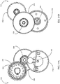
- the drive module 300 comprises an electrical assembly 340 and motor 578 shielded by a cover 304 and a gearbox 320 shielded by a cover 302.
- the drive module 300 is mounted to a seed meter 530.
- the seed meter is preferably of the type disclosed in Applicant's co-pending international patent application no. PCT/US2012/030192 , the disclosure of which is hereby incorporated herein in its entirety by reference.
- the drive module 300 is preferably mounted to a cover 532 shielding a seed disc 534 housed within the meter 530.
- the gearbox 320 includes an output gear 312 adapted to drive the seed disc 534 by sequential engagement with gear teeth arranged circumferentially around a perimeter of the seed disc 534.
- the drive module 300 further includes a housing 308 to which the covers 302,304 are mounted.
- the cover 302 preferably includes rubber grommet 305 for introducing electrical leads into the cover 302.
- the gearbox 320 includes an input shaft 325 and input gear 324 driven by the motor 578.
- the input gear drives a first step-down gear 326 and a second step-down gear 328.
- the second step-down gear 328 preferably has a smaller diameter than the first step-down gear 326.
- the second step-down gear 328 is preferably mounted coaxially to the first step-down gear 326, e.g., by press fitting.
- the second step-down gear 328 preferably drives an intermediate gear 322.
- the intermediate gear 322 drives the output gear 312 via a shaft 321.
- the electrical assembly 340 includes the circuit board 301, the motor encoder 576 (preferably including a magnetic encoder disc), and two leads 344a,344b in electrical communication with the motor 578 for driving the motor.
- the drive module 300 preferably includes mounting tabs 382,384,386,388 for mounting the drive module 300 to the seed meter 530 (e.g., by screws adapted to mate with threaded apertures in the cover 532).
- the conveyor module 400 preferably includes a bus node 402 (preferably a CAN node including a CAN transceiver, a controller, and a processor).
- the CAN node specifically the CAN transceiver, is preferably in electrical communication with the row bus 250.
- the conveyor module 400 preferably further includes a memory 406 and a processor 404 in electrical communication with a motor encoder signal conditioning chip 422, a motor PWM driver 448, and signal conditioning chips 432,434.
- the motor PWM driver 448 is in electrical communication with a conveyor motor 590 mounted to a conveyor 580.
- the motor encoder signal conditioning chip 422 is in electrical communication with a motor encoder 597 disposed to measure an operating speed of the conveyor motor 590.
- the signal conditioning chips 432,434 are preferably in electrical communication with optical sensors 582,584, respectively.
- a planter row unit 500 is illustrated with components of the control system 100 installed.
- the row unit 500 illustrated in FIG. 5A is one of the row units to which a multi-row control module 200 is mounted.
- a downforce actuator 510 (preferably a hydraulic cylinder) is mounted to the toolbar 14.
- the downforce actuator 510 is pivotally connected at a lower end to a parallel linkage 516.
- the parallel linkage 516 supports the row unit 500 from the toolbar 14, permitting each row unit to move vertically independently of the toolbar and the other spaced row units in order to accommodate changes in terrain or upon the row unit encountering a rock or other obstruction as the planter is drawn through the field.
- Each row unit 500 further includes a mounting bracket 520 to which is mounted a hopper support beam 522 and a subframe 524.
- the hopper support beam 522 supports a seed hopper 526 and a fertilizer hopper 528 as well as operably supporting a seed meter 530 and a seed tube 532.
- the subframe 524 operably supports a furrow opening assembly 534 and a furrow closing assembly 536.
- the furrow opening assembly 534 cuts a furrow 38 into the soil surface 40 as the planter is drawn through the field.
- the seed hopper 526 which holds the seeds to be planted, communicates a constant supply of seeds 42 to the seed meter 530.
- the drive module 300 is preferably mounted to the seed meter 530 as described elsewhere herein. As the drive module 300 drives the seed meter 530, individual seeds 42 are metered and discharged into the seed tube 532 at regularly spaced intervals based on the seed population desired and the speed at which the planter is drawn through the field.
- the seed sensor 508, preferably an optical sensor, is supported by the seed tube 532 and disposed to detect the presence of seeds 42 as they pass. The seed 42 drops from the end of the seed tube 532 into the furrow 38 and the seeds 42 are covered with soil by the closing wheel assembly 536.
- the furrow opening assembly 534 preferably includes a pair of furrow opening disk blades 544 and a pair of gauge wheels 548 selectively vertically adjustable relative to the disk blades 544 by a depth adjusting mechanism 568.
- the depth adjusting mechanism 568 preferably pivots about a downforce sensor 506, which preferably comprises a pin instrumented with strain gauges for measuring the force exerted on the gauge wheels 548 by the soil 40.
- the downforce sensor 506 is preferably of the type disclosed in Applicant's co-pending U.S. Patent Application No. 12/522,253 , the disclosure of which is hereby incorporated herein in its entirety by reference. In other embodiments, the downforce sensor is of the types disclosed in U.S. Patent No.
- the disk blades 544 are rotatably supported on a shank 554 depending from the subframe 524.
- Gauge wheel arms 560 pivotally support the gauge wheels 548 from the subframe 524.
- the gauge wheels 548 are rotatably mounted to the forwardly extending gauge wheel arms 560.
- the row unit illustrated in FIG. 5A does not include a conveyor 580 such that a conveyor module 400 is not required.
- FIG. 5B a planter row unit 500' including a conveyor 580 is illustrated with components of the control system 100 installed.
- the row unit 500' is similar to the row unit 500 described above, except that the seed tube 532 has been removed and replaced with a conveyor 580 configured to convey seeds at a controlled rate from the meter 530 to the furrow 42.
- the conveyor motor 590 is preferably mounted to the conveyor 580 and is configured to selectively drive the conveyor 580.
- the conveyor 580 is preferably one of the types disclosed in Applicant's U.S. patent application no. 61/539,786 and Applicant's co-pending international patent application no. PCT/US2012/057327 , the disclosures of which are hereby incorporated herein in their entirety by reference.
- the conveyor 580 preferably includes a belt 587 including flights 588 configured to convey seeds received from the seed meter 530 to a lower end of the conveyor.
- the seed conveyor 580 is preferably configured to drive the belt 587 in a clockwise direction.
- the seed conveyor 580 is preferably configured to guide seeds from an upper end of the conveyor down a forward side of the conveyor, such that seeds descend with flights 588 of the belt 587 on forward side of the conveyor 580 and are deposited from the lower end of the conveyor such that no seeds are present on flights 588 ascending the rearward side of the conveyor during normal operation.
- the optical sensor 582 is preferably mounted to the forward side of the conveyor 580 and disposed to detect seeds and descending conveyor flights 588 as they pass.
- the optical sensor 584 is preferably mounted to the rearward side of the conveyor 580 and disposed to detect ascending conveyor flights 588 as they return to the meter 530.
- the optical sensor 582 and/or the optical sensor 584 may be replaced with other object sensors configured to detect the presence of seeds and/or flights, such as an electromagnetic sensor as disclosed in Applicant's co-pending U.S. Patent Application No. 12/984,263 (Pub. No. US2012/0169353 ).
- row buses 250 are preferably configured to allow the user to install one or more additional CAN modules without replacing or modifying the row buses 250.
- a modified control system 100' includes modified row buses 250' having a modular extension 600 at each row.
- Each modular extension 600 preferably includes a first drop 610 and a second drop 620.
- Each drop 610, 620 preferably includes connections to power, ground and the bus signal lines (e.g., CAN Hi and CAN Lo).
- a modified control system 100" differs from control system 100' in that a conveyor module 400 has been connected to the first drop 610 of each modular extension 600. It should be appreciated that the second drop 620 is still available to add further modules to the row networks 130.
- each module is preferably configured to determine its identity (e.g., the row unit or row units 500 with which it is associated) and certain configuration data such as the relative location of its associated row unit.
- a configuration process 700 ( FIG. 7 ) is preferably carried out to identify the modules and transmit configuration data to each module.
- the monitor 110 preferably sends a first identification signal to the multi-row control module 200a via a point-to-point connection 160.
- the multi-row control module 200a preferably stores identification data (e.g., indicating its status as the leftmost multi-row control module) in memory.
- the multi-row control module 200a preferably sends a second identification signal to the multi-row control module 200b via a point-to-point electrical connection 161.
- the multi-row control module 200b preferably stores identification data (e.g., indicating its status as the rightmost multi-row control module) in memory.
- each row module e.g., each drive module 300 and each conveyor module 400 preferably determines the row unit 500 with which it is associated based on the voltage on an identification line (not shown) connecting the row module to the row bus 150.
- an identification line (not shown) connecting the row module to the row bus 150.
- three identification lines leading to the drive modules 300-1,300-2,300-3 are preferably connected to ground, a midrange voltage, and a high voltage, respectively.
- the monitor 110 preferably transmits row-network-specific configuration data to each multi-row control module 200 via the implement bus 150.
- the configuration data preferably includes transverse and travel-direction distances from each row unit 500 to the GPS receiver 166 and to the center of the toolbar 14 ("GPS offsets"); the row-network-specific GPS offsets sent to multi-row control module 200a at step 715 preferably corresponds to the row units 500-1,500-2,500-3 within the row network 130a.
- each multi-row control module 200 preferably transmits row-unit-specific configuration data to each row control module (e.g, the drive modules 300) via the row buses 250.
- the multi-row control module 200a preferably sends GPS offsets corresponding to row unit 500-1 to the drive module 300-1.
- the control system 100 preferably controls each drive module 300 according to a process 800.
- the monitor 110 preferably transmits an input prescription (e.g., a number of seeds per acre to be planted) to each multi-row control module 200 via the implement bus 150 of the implement network 135.
- the various kinematic sensors in the control system 100 transmit kinematic signals to the central processor 120.
- wheel speed sensors 164 and gyro 162 send speed signals and angular velocity signals, respectively, to the central processor 120 via point-to-point electrical connections.
- the monitor 110 also sends the speed reported by the speed sensor 168 to the central processor 120 via the implement bus 150, which speed is sent to the central processor 120 via the implement bus 150.
- the central processor 120 preferably calculates the speed of the center of the toolbar 14 and the angular velocity of the toolbar 14.
- the speed Sc of the center of the toolbar may be calculated by averaging the wheel speeds Swa,Swb reported by the wheel speed sensors 164a,164b, respectively or using the tractor speed reported by the speed sensor 168.
- the central processor 120 preferably transmits the planter speed and angular velocity to each multi-row control module 200 via the implement bus 150 of the implement network 135.
- each multi-row control module 200 preferably determines a meter speed command (e.g., a desired number of meter rotations per second) for each drive module within its row network 130.
- the meter speed command for each row unit 500 is preferably calculated based on a row-specific speed Sr of the row unit.
- the multi-row control module 200 preferably transmits the meter speed command determined for each drive module 300 to the respective drive module via the row bus 250 of the row network 130.
- the row bus 250 comprises a CAN bus
- the multi-row control module 200 preferably transmits a frame to the row bus having an identifier field specifying a drive module 300 (e.g., module 300-2) and a data field including the meter speed command for the specified drive module.
- the drive module 300 preferably compares the meter speed command R to a measured meter speed.
- the drive module 300 preferably calculates the measured meter speed using the time between encoder pulses received from the motor encoder 576.
- the drive module 300 preferably adjusts a voltage used to drive the meter 530 in order to adjust the measured meter speed closer to the meter speed command R.
- each seed sensor sends seed pulses to the associated multi-row control module 200.
- each seed sensor 508 preferably sends seed pulses to the associated multi-row control module 200 via point-to-point electrical connections.
- seed pulses preferably comprise signal pulses having maximum values exceeding a predetermined threshold.
- each seed sensor 582 preferably sends seed pulses to the associated multi-row control module 200 via the implement bus 250 of the row network 130.
- the seed pulses comprise signal pulses that differ by a predetermined threshold from signal pulses caused by passing flights of the conveyor. Alternative methods of detecting seeds in a seed conveyor 580 are described later herein.
- the multi-row control module 200 preferably calculates the population, singulation and seed spacing at each row unit 500 within the row network 130 using the row speed Sr and the seed pulses transmitted from each row unit within the row network.
- the multi-row module 200 transmits the population, singulation and spacing values to the central processor 120 via the implement bus 150 of the implement network 130.
- the central processor 120 preferably transmits the population, singulation and spacing values to the monitor 110 via the implement bus 150 of the implement network 135.
- each multi-row control module 200 preferably determines a conveyor speed command for each conveyor module 400 within the row network 130.
- the conveyor speed command is preferably selected such that a linear speed of flights traveling down the conveyor is approximately equal to the row-specific speed Sr; e.g., the conveyor motor speed command is preferably equal to the row-specific speed Sr multiplied by a predetermined constant.
- the multi-row control module 200 preferably transmits individual conveyor speed commands to each corresponding conveyor module 400 via the row bus 250 of the row network 130.
- the conveyor module 400 preferably compares the conveyor speed command to a measured conveyor speed.
- the conveyor speed is measured using the time between flight pulses resulting from conveyor flights passing the optical sensor 584. In other embodiments, the conveyor speed is measured using the time between encoder pulses received from the conveyor motor encoder 597.
- the conveyor module 400 preferably adjusts a voltage used to drive the conveyor motor 590 in order to adjust the measured meter speed closer to the conveyor speed command.
- the conveyor module 400 preferably performs the same steps 845 through 860 described herein with respect to process 800, specifically as those steps are described for embodiments including a conveyor 580.
- the control system 100 is preferably configured to count seeds, time-stamp seeds, and determine a seeding rate based on the signals generated by the first and second optical sensors 582, 584. It should be appreciated that in normal operation, the first optical sensor 582 detects both seeds and conveyor flights as the seeds from the meter 530 descend the conveyor 580, while the second optical sensor 584 detects only conveyor flights as they return to the top of the conveyor after seeds are deposited. The shape and size of flights in the conveyor 580 are preferably substantially consistent.
- the monitor 110 (or in some embodiments the central processor 120) is preferably configured to carry out a process 1700 for detecting seeds.
- the monitor 110 preferably receives signals from both the first optical sensor 582 and the second optical sensor 584 over a measuring period.
- a first optical sensor signal 1810 (in which amplitude increases when either flights or seeds pass) and a second optical sensor signal 1820 (in which amplitude increases when flights pass) are illustrated on an exemplary multi-signal graph 1800 in FIG. 18 .
- the control system 100 preferably changes the conveyor speed during the measuring period such that the length of signal pulses resulting from belts having the same length (as best illustrated by viewing the varying-width pulses in the sensor signal 1820).
- the monitor 110 preferably applies a time shift Ts (e.g., the time shift Ts illustrated in FIG. 18 ) to the second optical sensor signal 1820, resulting in a time-shifted sensor signal 1820'.
- k Tf ⁇ DEC Ds Df
- the monitor 110 preferably calculates k empirically in a setup stage while seeds are not being planted by running the conveyor 580 at a constant speed and determining the values of Tf and Ts; with no seeds on the belt, the value of Ts may be determined by measuring the time between a flight pulse at the first optical sensor 582 and the next subsequent flight pulse at the second optical sensor 584.
- the sensors 582, 584 are positioned at a relative distance Ds equal to an integer multiple of Df such that no time shift or a near-zero time shift is required.
- the monitor 110 preferably subtracts the time-shifted second optical sensor signal 1820' from the first optical sensor signal 1810, resulting in a flight-corrected signal 1830 (see FIG. 18 ) which correlates to the signal from the first optical sensor signal with signal pulses resulting from conveyor flights substantially eliminated.
- the monitor 110 preferably compares pulses 1832 in the flight-corrected signal 1830 to one or more seed pulse validity thresholds (e.g., a minimum amplitude threshold and a minimum period threshold); the monitor preferably identifies each pulse exceeding the seed pulse validity thresholds as valid seed event.
- the monitor 110 preferably adds the identified seed event to a seed count.
- the monitor 110 preferably stores the seed count; seeding rate (e.g., the seed count over a predetermined time period); a time associated with the seed event, seed count, or seeding rate; and a GPS associated with the seed event, seed count, or seeding rate to memory for mapping, display and data storage.
- seeding rate e.g., the seed count over a predetermined time period
- time associated with the seed event, seed count, or seeding rate e.g., the seed count over a predetermined time period
- a time associated with the seed event, seed count, or seeding rate e.g., the seed count over a predetermined time period
- a time associated with the seed event, seed count, or seeding rate e.g., the seed count over a predetermined time period
- GPS e.g., the seed count over a predetermined time period
- each of a plurality of row networks 132 includes a single-row control module 202 mounted to one of the row units 500, a row bus 250, a drive module 300 individually mounted to the same row unit 500, and a conveyor module 400 individually mounted to the same row unit 500.
- the single-row control module 202 preferably includes equivalent components to the multi-row control module 200, except that the downforce signal conditioning chip 206, seed sensor auxiliary input 208, and the downforce solenoid PWM driver 210 are only in electrical communication with one of the corresponding devices mounted to the same row unit 500.
- the row bus 250 is in electrical communication with a single drive module 300 and a single conveyor module 400 as well as the single-row control module 202.
- two seed meters 530 are mounted to a single row unit 500 as described in U.S. Provisional Patent Application No. 61/838,141 .
- a drive module 300 is operably coupled to each seed meter 530.
- a row network 132' having two drive modules 300 is illustrated in FIG. 19 .
- the row network 132' preferably includes a single-row control module 202, a row bus 250, a first drive module 300a (preferably mounted to the row unit 500), a second drive module 300b (preferably mounted to the row unit 500), a conveyor module 400, an input controller 307 and an identification power source 309.
- the first drive module 300a and the second drive module 300b, including the hardware and software components, are preferably substantially identical.
- the single-row control module 202, the first drive module 300a, the second drive module 300b, and the conveyor module 250 are preferably in electrical communication with the row bus 250.
- the single-row control module 202 is preferably in electrical communication with an implement bus 150 of one of the control system embodiments described herein.
- the first drive module 300a is preferably in electrical communication with the identification power source 309 and the input controller 307.
- the first drive module 300a is preferably in electrical communication with the input controller 307 via an electrical line 311.
- the identification power source 309 preferably supplies a low-voltage signal to the first drive module 300a, and may comprise a point-to-point connection to a power source including a relatively large resistor.
- the input controller 307 is preferably a swath and/or rate controller configured to shut off and/or modify an application rate of a crop input such as (without limitation) liquid fertilizer, dry fertilizer, liquid insecticide, or dry insecticide.
- the first drive module 300a receives a signal from the identification power source 309 and sends a corresponding identification signal to the monitor 110 (and/or the central processor 120) identifying itself as the first drive module 300a. Subsequently, the monitor 110 (and/or the central processor 120) preferably sends commands to the first drive module 300a and stores data received from the first drive module 300a based on the identification signal.
- the monitor 110 determines which seed meter 530 should be seeding by comparing position information received from the GPS receiver 166 to an application map. The monitor 110 then preferably commands the single-row control module 202 to send a desired seeding rate to the drive module associated with the meter 530 that should be seeding, e.g., the first drive module 300a.
- the first drive module 300a preferably sends a command signal to the input controller commanding the input controller to turn off the associated input, e.g., by closing a valve.
- the drive module 300 transmits a first signal (e.g., a high signal) via the line 311 to the input controller 307 when the drive module is commanding the seed meter to plant, and transmits a second signal (e.g., a low signal) or no signal when the drive module is not commanding the seed meter to plant.
- the line 311 is preferably configured for electrical communication with any one of a plurality of input controllers, e.g. by incorporating a standard electrical connector.
- the first and second signal are preferably selected to correspond to swath commands recognized by any one of a plurality of input controllers such that the input controller 307 turns off the crop input when the seed meter 530 is not planting and turns on the crop input when the seed meter 530 is planting.
- the first drive module 300a preferably receives a signal from the row bus 250 (preferably generated either by the single-row control module 202 or the second drive module 300b) indicating whether the second drive module is commanding its associated seed meter 530 to plant. The first drive module 300a then determines whether either the first drive module 300a or 300b is commanding either of the seed meters 530 to plant. If neither of the drive modules 300a, 300b are commanding either seed meter to plant, the first drive module 300a preferably sends a first signal to the input controller 307 via the line 311.
- the input controller 307 is preferably configured to turn off the crop input (e.g., by closing a valve) upon receiving the first signal. If either of the drive modules 300a, 300b are commanding either seed meter to plant the first drive module 300a preferably sends a second signal (or in some embodiments no signal) to the input controller 307 such that the input controller does not turn off the crop input.
- the monitor 110 (and/or the central processor 120) preferably determines a desired crop input application rate and transmits a corresponding signal to the input controller.
- the invention comprises a monitoring system for an agricultural implement having a plurality of row units, comprising:
- Said first seed sensor may comprise an optical sensor
- said second seed sensor may comprise an optical sensor
- the monitoring system may further include:
- Said first signal may include a seed pulse portion and a flight pulse portion, and wherein said monitor may be configured to distinguish between said seed pulse portion and said flight pulse portion by comparing said first signal to said second signal.
- Said monitor may be configured to identify said seed pulse portion based on the timing of a flight pulse in said second signal.
- Said monitor may be configured to apply a time shift to said second signal. Said time shift may be related to one of the relative position of the first and second seed sensor and the distance between adjacent flights and the time between a pulse in said first signal and an immediately subsequent pulse in said second signal.
- a method for monitoring an agricultural implement comprises:
- the method may further include:
- the method may further include:
- the method may further include:
- the method may further include:
- Components described herein as being in electrical communication may be in data communication (e.g., enabled to communicate information including analog and/or digital signals) by any suitable device or devices including wireless communication devices (e.g., radio transmitters and receivers).
- wireless communication devices e.g., radio transmitters and receivers.
Priority Applications (1)
| Application Number | Priority Date | Filing Date | Title |
|---|---|---|---|
| EP21205778.0A EP3967121A1 (fr) | 2012-07-25 | 2013-07-25 | Système de commande et de surveillance d'un engin agricole multirangs |
Applications Claiming Priority (3)
| Application Number | Priority Date | Filing Date | Title |
|---|---|---|---|
| US201261675714P | 2012-07-25 | 2012-07-25 | |
| EP13823843.1A EP2876993B1 (fr) | 2012-07-25 | 2013-07-25 | Système et procédé de commande et de surveillance de machine agricole multirangs |
| PCT/US2013/051971 WO2014018717A1 (fr) | 2012-07-25 | 2013-07-25 | Systèmes, procédés et appareil de commande et de surveillance de machine agricole multirangs |
Related Parent Applications (1)
| Application Number | Title | Priority Date | Filing Date |
|---|---|---|---|
| EP13823843.1A Division EP2876993B1 (fr) | 2012-07-25 | 2013-07-25 | Système et procédé de commande et de surveillance de machine agricole multirangs |
Related Child Applications (2)
| Application Number | Title | Priority Date | Filing Date |
|---|---|---|---|
| EP21205778.0A Division EP3967121A1 (fr) | 2012-07-25 | 2013-07-25 | Système de commande et de surveillance d'un engin agricole multirangs |
| EP21205778.0A Division-Into EP3967121A1 (fr) | 2012-07-25 | 2013-07-25 | Système de commande et de surveillance d'un engin agricole multirangs |
Publications (2)
| Publication Number | Publication Date |
|---|---|
| EP3259972A1 true EP3259972A1 (fr) | 2017-12-27 |
| EP3259972B1 EP3259972B1 (fr) | 2021-12-08 |
Family
ID=49997824
Family Applications (3)
| Application Number | Title | Priority Date | Filing Date |
|---|---|---|---|
| EP13823843.1A Active EP2876993B1 (fr) | 2012-07-25 | 2013-07-25 | Système et procédé de commande et de surveillance de machine agricole multirangs |
| EP17173466.8A Active EP3259972B1 (fr) | 2012-07-25 | 2013-07-25 | Système et procédé de commande et de surveillance d'un engin agricole multirangs |
| EP21205778.0A Pending EP3967121A1 (fr) | 2012-07-25 | 2013-07-25 | Système de commande et de surveillance d'un engin agricole multirangs |
Family Applications Before (1)
| Application Number | Title | Priority Date | Filing Date |
|---|---|---|---|
| EP13823843.1A Active EP2876993B1 (fr) | 2012-07-25 | 2013-07-25 | Système et procédé de commande et de surveillance de machine agricole multirangs |
Family Applications After (1)
| Application Number | Title | Priority Date | Filing Date |
|---|---|---|---|
| EP21205778.0A Pending EP3967121A1 (fr) | 2012-07-25 | 2013-07-25 | Système de commande et de surveillance d'un engin agricole multirangs |
Country Status (12)
| Country | Link |
|---|---|
| US (4) | US9332689B2 (fr) |
| EP (3) | EP2876993B1 (fr) |
| AR (1) | AR092357A1 (fr) |
| AU (2) | AU2013295763B2 (fr) |
| BR (1) | BR112015001540B1 (fr) |
| CA (2) | CA2879731C (fr) |
| ES (2) | ES2629517T3 (fr) |
| HU (1) | HUE032580T2 (fr) |
| LT (2) | LT3259972T (fr) |
| UA (1) | UA113660C2 (fr) |
| WO (1) | WO2014018717A1 (fr) |
| ZA (1) | ZA201500484B (fr) |
Cited By (3)
| Publication number | Priority date | Publication date | Assignee | Title |
|---|---|---|---|---|
| EP3808166A1 (fr) * | 2019-10-18 | 2021-04-21 | Deere & Company | Système pour commander la position d'une machine |
| US11140812B2 (en) | 2017-12-15 | 2021-10-12 | Kinze Manufacturing, Inc. | Systems, methods, and apparatus for controlling downforce of an agricultural implement |
| US11224153B2 (en) | 2017-07-28 | 2022-01-18 | Kinze Manufacturing, Inc. | Agricultural implement and row units including double acting actuator systems, methods, and apparatus |
Families Citing this family (132)
| Publication number | Priority date | Publication date | Assignee | Title |
|---|---|---|---|---|
| US8850995B2 (en) | 2009-02-02 | 2014-10-07 | Deere & Company | Seeding machine with seed delivery system |
| US8671856B2 (en) | 2009-02-02 | 2014-03-18 | Deere & Company | Planting unit for a seeding machine having blocking member to control hand-off of seed from a seed meter to a seed delivery system |
| US10327374B2 (en) | 2011-04-27 | 2019-06-25 | Kinze Manufacturing, Inc. | Remote adjustment of a row unit of an agricultural device |
| AR093728A1 (es) | 2011-06-03 | 2015-06-24 | Prec Planting Llc | Metodos, sistemas y aparatos con barras de herramienta de aplicacion en la agricultura |
| CA2850160C (fr) | 2011-09-27 | 2022-01-25 | Precision Planting Llc | Appareil, systemes et procedes de distribution de graines |
| WO2014018717A1 (fr) * | 2012-07-25 | 2014-01-30 | Precision Planting Llc | Systèmes, procédés et appareil de commande et de surveillance de machine agricole multirangs |
| EP3878261A1 (fr) | 2012-08-10 | 2021-09-15 | The Climate Corporation | Procédé de surveillance d'applications agricoles |
| EP2931021B1 (fr) | 2012-12-17 | 2021-06-23 | The Climate Corporation | Procédé pour la mise en oeuvre d'un placement de parcelles |
| FR3001607B1 (fr) * | 2013-02-07 | 2015-02-20 | Kuhn Sa | Semoir monograine avec au moins un element semeur perfectionne |
| US10390478B2 (en) | 2013-04-30 | 2019-08-27 | Precision Planting Llc | Application control and monitoring apparatus, systems, and methods |
| US10064327B2 (en) | 2015-07-03 | 2018-09-04 | Amvac Chemical Corporation | Apparatus and method for minimizing the volume of a liquid carrier used for delivering agricultural products into a furrow during planting |
| US10470356B2 (en) | 2013-08-27 | 2019-11-12 | Amvac Chemical Corporation | System and method for dispensing multiple low rate agricultural products |
| US9820431B2 (en) | 2013-08-27 | 2017-11-21 | American Vanguard Corporation | System and process for dispensing multiple and low rate agricultural products |
| US11026362B2 (en) | 2013-08-27 | 2021-06-08 | Amvac Chemical Corporation | System and method for treating individual seeds with liquid chemicals during the planting process |
| US11058046B2 (en) | 2013-08-27 | 2021-07-13 | Amvac Chemical Corporation | System and method for dispensing multiple low rate agricultural products |
| US10058023B2 (en) | 2016-07-13 | 2018-08-28 | Amvac Chemical Corporation | Electronically pulsing agricultural product with seed utilizing seed transport mechanism |
| US10517206B2 (en) | 2013-08-27 | 2019-12-31 | Amvac Chemical Corporation | System for providing prescriptive application of multiple products |
| US9769978B2 (en) | 2013-08-30 | 2017-09-26 | Precision Planting Llc | Seed delivery apparatus, systems, and methods |
| EP3072025B1 (fr) * | 2013-11-18 | 2020-01-22 | AGCO Corporation | Système et procédé de génération automatique de points de cheminement et de lignes de cheminement pour le guidage d'un véhicule |
| US9775279B2 (en) * | 2014-05-09 | 2017-10-03 | Deere & Company | Seed valve and planting method for multiple seed types |
| US9883625B2 (en) | 2014-08-21 | 2018-02-06 | Precision Planting Llc | Crop input variety selection systems |
| US10109024B2 (en) * | 2014-09-05 | 2018-10-23 | The Climate Corporation | Collecting data to generate an agricultural prescription |
| US10393722B2 (en) | 2015-01-30 | 2019-08-27 | The Climate Corporation | Soil quality measurement device |
| UA125462C2 (uk) | 2015-04-29 | 2022-03-16 | Зе Клаймат Корпорейшн | Системи, способи та пристрої для моніторингу за погодними та польовими умовами |
| WO2016187540A1 (fr) * | 2015-05-20 | 2016-11-24 | Kinze Manufacturing, Inc. | Rayonneur à dispositif d'ouverture à tige |
| US10791666B2 (en) | 2015-06-08 | 2020-10-06 | The Climate Corporation | Agricultural data analysis |
| US9964648B2 (en) * | 2015-06-16 | 2018-05-08 | Insero LLC | Guidiance system and method based on dead reckoning positioning and heading augmented by GNSS and predictive path selection |
| CA2990438A1 (fr) | 2015-06-30 | 2017-01-05 | The Climate Corporation | Systemes et procedes pour la capture d'images et l'analyse de champs agricoles |
| UA123314C2 (uk) | 2015-07-10 | 2021-03-17 | Пресіжн Плентінг Елелсі | Висівна секція сівалки |
| ES2942267T3 (es) | 2015-07-15 | 2023-05-31 | Climate Llc | Generación de modelos digitales de nutrientes disponibles en un cultivo durante el curso del desarrollo del cultivo en función de datos meteorológicos y del suelo |
| US10416351B2 (en) | 2015-09-10 | 2019-09-17 | The Climate Corporation | Generating probabilistic estimates of rainfall rates from radar reflectivity measurements |
| US10025983B2 (en) | 2015-09-21 | 2018-07-17 | The Climate Corporation | Ponding water detection on satellite imagery |
| US9635802B2 (en) * | 2015-10-02 | 2017-05-02 | Deere & Company | Automatic seeding system motor reversal |
| US10303677B2 (en) | 2015-10-14 | 2019-05-28 | The Climate Corporation | Computer-generated accurate yield map data using expert filters and spatial outlier detection |
| US10342174B2 (en) | 2015-10-16 | 2019-07-09 | The Climate Corporation | Method for recommending seeding rate for corn seed using seed type and sowing row width |
| US10246274B2 (en) | 2015-11-04 | 2019-04-02 | Cnh Industrial Canada, Ltd. | Systems and methods for air cart pressurization monitoring |
| US9721181B2 (en) | 2015-12-07 | 2017-08-01 | The Climate Corporation | Cloud detection on remote sensing imagery |
| US10628895B2 (en) | 2015-12-14 | 2020-04-21 | The Climate Corporation | Generating digital models of relative yield of a crop based on nitrate values in the soil |
| US10251347B2 (en) | 2016-01-07 | 2019-04-09 | The Climate Corporation | Generating digital models of crop yield based on crop planting dates and relative maturity values |
| US10331931B2 (en) | 2016-02-05 | 2019-06-25 | The Climate Corporation | Modeling trends in crop yields |
| US10754063B2 (en) * | 2016-06-14 | 2020-08-25 | The Climate Corporation | Supervised neural network to predict unlabeled rain rates |
| US10719638B2 (en) | 2016-08-11 | 2020-07-21 | The Climate Corporation | Delineating management zones based on historical yield maps |
| US10165724B2 (en) | 2016-10-07 | 2019-01-01 | Crary Industries, Inc. | Potato seed planting apparatus and method of planting potato seed using the apparatus |
| AU2017355315B2 (en) | 2016-11-07 | 2023-12-14 | Climate Llc | Work layer imaging and analysis for implement monitoring, control and operator feedback |
| US10398096B2 (en) | 2016-11-16 | 2019-09-03 | The Climate Corporation | Identifying management zones in agricultural fields and generating planting plans for the zones |
| US10509872B2 (en) | 2017-03-08 | 2019-12-17 | The Climate Corporation | Location selection for treatment sampling |
| US10455758B2 (en) | 2017-05-11 | 2019-10-29 | Cnh Industrial America Llc | Seed level detection in a seed meter |
| UA125616C2 (uk) | 2017-05-26 | 2022-05-04 | Пресіжн Плантінг Ллк | Спосіб запобігання зміщенню сільськогосподарського знаряддя |
| US10602656B2 (en) | 2017-08-04 | 2020-03-31 | Deere & Company | Skip compensation system |
| US10225978B1 (en) | 2017-09-14 | 2019-03-12 | Cnh Industrial America Llc | System and method for switching between seed types during a multi-variety seed planting operation |
| US10842072B2 (en) | 2017-09-29 | 2020-11-24 | Kinze Manufacturing, Inc. | Planter with high speed seed delivery apparatus |
| WO2019070820A1 (fr) | 2017-10-03 | 2019-04-11 | Ag Leader Technology | Appareil de mesure d'impulsions d'air contrôlées pour planteuse agricole et systèmes et procédés associés |
| US11140805B2 (en) | 2017-11-21 | 2021-10-12 | Cnh Industrial Canada, Ltd. | Independent ground engaging tool depth control |
| US10408667B2 (en) | 2017-12-22 | 2019-09-10 | Cnh Industrial America Llc | Calibration methods for multi-variety seed meters and related systems |
| US10823748B2 (en) | 2018-01-15 | 2020-11-03 | Precision Planting Llc | Seed delivery systems and mapping of row speeds |
| US11277961B2 (en) | 2018-02-09 | 2022-03-22 | Ag Leader Technology | Seed spacing device for an agricultural planter and related systems and methods |
| US11013164B1 (en) | 2018-02-28 | 2021-05-25 | Precision Planting Llc | Index-based planting consistency tracking |
| WO2019173754A1 (fr) | 2018-03-08 | 2019-09-12 | Precision Planting Llc | Système de régulation de fluide |
| US10820488B2 (en) | 2018-03-16 | 2020-11-03 | Cnh Industrial America Llc | Systems and methods for monitoring the operation of a seed meter |
| US10750662B2 (en) | 2018-06-01 | 2020-08-25 | Deere & Company | Seed sensor |
| US11058047B2 (en) | 2018-06-27 | 2021-07-13 | Deere & Company | Seeding system |
| US11051445B2 (en) | 2018-06-27 | 2021-07-06 | Deere & Company | Seeding system |
| US11064649B2 (en) | 2018-06-27 | 2021-07-20 | Deere & Company | Seeding system |
| AR112430A1 (es) * | 2018-06-28 | 2019-10-30 | Gustavo Alejandro Boetsch | Distribuidor de semillas para máquinas sembradoras |
| WO2020023392A1 (fr) * | 2018-07-26 | 2020-01-30 | The Climate Corporation | Génération de cartes de rendement agronomique à partir d'une imagerie de santé de champ |
| CN109197052A (zh) * | 2018-08-06 | 2019-01-15 | 王运祥 | 一种用于小型农田种植的黄豆播种机 |
| US11596119B2 (en) | 2018-08-13 | 2023-03-07 | Climate Llc | Digital nutrient models using spatially distributed values unique to an agronomic field |
| USD908277S1 (en) | 2018-08-25 | 2021-01-19 | Amvac Chemical Corporation | Container for dry products |
| BR112021003593A2 (pt) | 2018-08-28 | 2021-05-18 | AMVAC Hong Kong Limited | sistema de recipiente para transportar e distribuir produtos agrícolas, montagem de alojamento para um sistema de recipiente configurado para transportar e distribuir produtos agrícolas, recipiente para distribuir produtos agrícolas de melhoria de colheita, recipiente para distribuir produtos agrícolas de melhoria de colheita granulares e secos e recipiente para distribuir produtos agrícolas de melhoria de colheita líquidos |
| US11382261B2 (en) | 2018-08-28 | 2022-07-12 | Amvac Chemical Corporation | System and method for stacking containers |
| CA3114956A1 (fr) | 2018-10-19 | 2020-04-23 | The Climate Corporation | Techniques d'apprentissage machine pour identifier des nuages et des ombres en nuage dans une imagerie par satellite |
| AR116767A1 (es) | 2018-10-19 | 2021-06-09 | Climate Corp | Detección de infecciones de enfermedades de plantas mediante la clasificación de fotografías de plantas |
| US10713542B2 (en) | 2018-10-24 | 2020-07-14 | The Climate Corporation | Detection of plant diseases with multi-stage, multi-scale deep learning |
| US11464177B2 (en) | 2018-12-10 | 2022-10-11 | Climate Llc | Image-based irrigation recommendations |
| BR112021010115A2 (pt) | 2018-12-20 | 2021-08-24 | The Climate Corporation | Utilizando modelos estatísticos espaciais para implementar ensaios agronômicos |
| US11906621B2 (en) | 2018-12-21 | 2024-02-20 | Climate Llc | Quantitative precipitation estimate quality control |
| US11523554B2 (en) | 2019-01-25 | 2022-12-13 | Ag Leader Technology | Dual seed meter and related systems and methods |
| US11191204B2 (en) | 2019-02-18 | 2021-12-07 | Cnh Industrial Canada, Ltd. | System and method for monitoring soil conditions within a field |
| EP3811404B1 (fr) | 2019-03-04 | 2023-06-28 | Climate LLC | Dispositif de maintien et de transfert de données de système informatique d'intelligence agricole |
| US11202404B2 (en) * | 2019-03-05 | 2021-12-21 | Deere & Company | Planter row unit downforce control with ground view sensor |
| US11134606B2 (en) | 2019-03-08 | 2021-10-05 | Deere & Company | Planter row unit with load sensing depth stop assembly |
| US11533837B2 (en) | 2019-03-22 | 2022-12-27 | Capstan Ag Systems, Inc. | Systems and methods for spraying seeds dispensed from a high-speed planter |
| US11197407B2 (en) | 2019-04-29 | 2021-12-14 | Cnh Industrial Canada, Ltd. | Implement mounted sensors to increase seeding productivity |
| US11622494B2 (en) | 2019-05-10 | 2023-04-11 | Great Plains Manufacturing, Inc. | Tillage implement with vision sensors |
| AU2020284512A1 (en) * | 2019-05-31 | 2021-12-23 | Precision Planting Llc | Methods and systems for using duty cycle of sensors to determine seed or particle flow rate |
| US11785881B2 (en) | 2019-08-19 | 2023-10-17 | Ag Leader Technology | Adjustable seed meter and related systems and methods |
| WO2021033035A1 (fr) | 2019-08-21 | 2021-02-25 | Precision Planting Llc | Système et procédé de marquage de champ |
| US11445658B2 (en) | 2019-08-26 | 2022-09-20 | Deere & Company | Systems and methods for selective fertilizer placement |
| US11877530B2 (en) | 2019-10-01 | 2024-01-23 | Ag Leader Technology | Agricultural vacuum and electrical generator devices, systems, and methods |
| US11974517B2 (en) | 2019-10-31 | 2024-05-07 | Deere & Company | Agricultural seed detection and tracking system |
| US11602095B2 (en) | 2019-10-31 | 2023-03-14 | Deere & Company | Precision agricultural seed delivery system |
| US11425855B2 (en) * | 2019-10-31 | 2022-08-30 | Deere & Company | Agricultural seed delivery system using target location map |
| CA3097708A1 (en) | 2019-11-14 | 2021-05-14 | Cnh Industrial Canada, Ltd. | Particulate material metering system for an agricultural implement |
| US11765991B2 (en) | 2019-11-14 | 2023-09-26 | Cnh Industrial Canada, Ltd. | Particulate material metering system for an agricultural implement |
| US11939982B2 (en) * | 2019-12-09 | 2024-03-26 | Cnh Industrial America Llc | System for distributing particulate material from an agricultural machine |
| US11553639B2 (en) | 2019-12-24 | 2023-01-17 | Cnh Industrial America Llc | Particle delivery system of an agricultural row unit |
| US11582899B2 (en) | 2019-12-24 | 2023-02-21 | Cnh Industrial America Llc | Particle delivery system of an agricultural row unit |
| US11490558B2 (en) | 2019-12-24 | 2022-11-08 | Cnh Industrial America Llc | Particle delivery system of an agricultural row unit |
| US11564346B2 (en) | 2019-12-24 | 2023-01-31 | Cnh Industrial America Llc | Particle delivery system of an agricultural row unit |
| US11483963B2 (en) | 2019-12-24 | 2022-11-01 | Cnh Industrial America Llc | Particle delivery system of an agricultural row unit |
| US11523555B2 (en) | 2019-12-24 | 2022-12-13 | Cnh Industrial America Llc | Particle delivery system of an agricultural row unit |
| US11596095B2 (en) | 2019-12-24 | 2023-03-07 | Cnh Industrial America Llc | Particle delivery system of an agricultural row unit |
| US11564344B2 (en) | 2019-12-24 | 2023-01-31 | Cnh Industrial America Llc | Particle delivery system of an agricultural row unit |
| US11516958B2 (en) | 2019-12-24 | 2022-12-06 | Cnh Industrial America Llc | Particle delivery system of an agricultural row unit |
| US11523556B2 (en) | 2019-12-24 | 2022-12-13 | Cnh Industrial America Llc | Particle delivery system of an agricultural row unit |
| US11553638B2 (en) | 2019-12-24 | 2023-01-17 | Cnh Industrial America Llc | Particle delivery system of an agricultural row unit |
| US11589500B2 (en) | 2019-12-24 | 2023-02-28 | Cnh Industrial America Llc | Particle delivery system of an agricultural row unit |
| KR20220139353A (ko) * | 2020-02-11 | 2022-10-14 | 티에스아이 인코포레이티드 | 시드 분배 시스템을 위한 광전 센서 |
| AR121386A1 (es) | 2020-02-21 | 2022-06-01 | Climate Corp | Señalización de diferencias operacionales en implementos agrícolas |
| WO2021173908A1 (fr) * | 2020-02-27 | 2021-09-02 | Farm Right, Llc | Machine de plantation de graines |
| AU2021251467A1 (en) | 2020-04-06 | 2022-11-03 | Precision Planting Llc | Row cleaner |
| US11937531B2 (en) | 2020-06-08 | 2024-03-26 | Deere & Company | Systems and methods for selective material placement |
| CN112075168A (zh) * | 2020-08-03 | 2020-12-15 | 昆明理工大学 | 一种开沟-排种复合单体式参类精密播种机 |
| CN114077946A (zh) * | 2020-08-14 | 2022-02-22 | 上海柏鼎环保科技有限公司 | 场地调查监管系统及方法 |
| US20240049623A1 (en) | 2021-02-17 | 2024-02-15 | Precision Planting Llc | Mix calculator |
| AU2022223735A1 (en) | 2021-02-17 | 2023-07-13 | Precision Planting Llc | Multiple networks monitor |
| CA3202239A1 (fr) | 2021-02-17 | 2022-08-25 | Precision Planting Llc | Transfert de donnees |
| AU2022242863A1 (en) | 2021-03-24 | 2023-07-27 | Precision Planting Llc | Systems and methods for determining state data for agricultural parameters and providing spatial state maps |
| AU2022274362A1 (en) | 2021-05-10 | 2023-08-03 | Precision Planting Llc | Integrated communication and lighting system |
| EP4351305A1 (fr) | 2021-06-07 | 2024-04-17 | Precision Planting LLC | Systèmes et procédés permettant de fournir des vues de champ comprenant des cartes agricoles améliorées ayant une couche de données et des données d'image |
| GB202108558D0 (en) | 2021-06-16 | 2021-07-28 | Prec Planting Llc | Systems and methods for providing field views including enhanced agricultural maps having a data layer and image data |
| AU2022362834A1 (en) | 2021-10-11 | 2024-03-14 | Precision Planting Llc | Seed accelerator |
| AU2022365454A1 (en) | 2021-10-12 | 2024-03-28 | Precision Planting Llc | Seed boot |
| AU2022364251A1 (en) | 2021-10-12 | 2024-03-28 | Precision Planting Llc | Wedge |
| GB202114711D0 (en) | 2021-10-14 | 2021-12-01 | Prec Planting Llc | Seed accelerator |
| GB202114712D0 (en) | 2021-10-14 | 2021-12-01 | Prec Planting Llc | Seed accelerator |
| GB202115117D0 (en) | 2021-10-21 | 2021-12-08 | Prec Planting Llc | Seed boot |
| WO2023214220A1 (fr) | 2022-05-02 | 2023-11-09 | Precision Planting Llc | Systèmes et procédés de détection de plante basée sur la vision et technologie d'application de reconnaissance |
| WO2023229848A1 (fr) * | 2022-05-24 | 2023-11-30 | N.S. Farms LLC | Dispositif de dispersion de graines destiné à être utilisé avec un équipement de récolte de moissonneuse-batteuse |
| GB202212355D0 (en) | 2022-08-25 | 2022-10-12 | Agco Int Gmbh | Multi-row unit controller for controlling and monitoring row units of an agricultural implement and related methods and systems |
| WO2024052792A1 (fr) | 2022-09-09 | 2024-03-14 | Precision Planting Llc | Accélérateur de semences à entraînement d'air |
| CN117084026B (zh) * | 2023-08-10 | 2024-04-05 | 山东省农业机械科学研究院 | 一种播种监测装置及监测方法 |
Citations (5)
| Publication number | Priority date | Publication date | Assignee | Title |
|---|---|---|---|---|
| US6389999B1 (en) | 2001-11-02 | 2002-05-21 | Dennis Duello | Dynamic controller of excess downpressure for surface engaging implement |
| US20030159631A1 (en) * | 2002-02-26 | 2003-08-28 | Precision Planting, Inc. | Apparatus and Method for Controlled Delivery of Seeds to an Open Furrow. |
| US20060011647A1 (en) * | 2004-07-15 | 2006-01-19 | Precision Planting, Inc. | Apparatus and method for testing seed singulation of a seed meter |
| EP2213153A1 (fr) * | 2009-02-02 | 2010-08-04 | Deere & Company | Appareil de distribution de graines et procédé pour distribuer des graines |
| US20120169353A1 (en) | 2011-01-04 | 2012-07-05 | Precision Planting, Inc. | Seed tube egress-mounted seed sensor |
Family Cites Families (21)
| Publication number | Priority date | Publication date | Assignee | Title |
|---|---|---|---|---|
| US6070539A (en) * | 1997-03-21 | 2000-06-06 | Case Corporation | Variable rate agricultural product application implement with multiple inputs and feedback |
| US6082184A (en) | 1997-05-27 | 2000-07-04 | Martin Lehmann | Method for leak testing and leak testing apparatus |
| US6009354A (en) * | 1997-09-23 | 1999-12-28 | Case Corporation | Enhanced implement control |
| US6522948B1 (en) * | 2000-08-14 | 2003-02-18 | Flexi-Coil Ltd. | Agricultural product application tracking and control |
| CA2423894A1 (fr) * | 2000-09-28 | 2002-04-04 | Noel D. Lempriere | Doseur de graines |
| US6938564B2 (en) | 2003-06-03 | 2005-09-06 | Amvac Chemical Corporation | Method and system for concentrating chemical granules around a planted seed |
| US7162963B2 (en) * | 2004-08-16 | 2007-01-16 | Precision Planting, Inc. | Adjustable singulating brush assembly and method of singulating seeds |
| US20060283363A1 (en) * | 2005-06-07 | 2006-12-21 | Wollman Albert E | Potato Planter Improvement to Reduce Skips and Rolling |
| US7631606B2 (en) * | 2005-08-19 | 2009-12-15 | Precision Planting, Inc. | Seed belt for an agricultural planter |
| US7481171B2 (en) | 2005-08-30 | 2009-01-27 | Howard D Martin | Single disc liquid fertilizer opener |
| US8561472B2 (en) | 2007-01-08 | 2013-10-22 | Precision Planting Llc | Load sensing pin |
| PL2104413T5 (pl) | 2007-01-08 | 2020-07-13 | The Climate Corporation | Układ i sposób monitorowania siewnika |
| US8504310B2 (en) * | 2009-08-05 | 2013-08-06 | Deere & Company | Particulate flow sensing for an agricultural implement |
| US7918168B2 (en) * | 2009-02-02 | 2011-04-05 | Deere & Company | Differential pressure seed meter with an endless belt seed transport member |
| US7726251B1 (en) * | 2009-03-11 | 2010-06-01 | Deere & Company | Agricultural seeding apparatus and method for seed placement synchronization between multiple rows |
| US9055712B2 (en) | 2010-09-15 | 2015-06-16 | Dawn Equipment Company | Agricultural apparatus with integrated controller for a row unit |
| JP5465337B2 (ja) | 2010-10-28 | 2014-04-09 | 京セラ株式会社 | 積層型圧電素子およびそれを用いた噴射装置ならびに燃料噴射システム |
| LT3235360T (lt) | 2011-03-22 | 2019-11-11 | Prec Planting Llc | Sėklų dozatorius |
| CA2850160C (fr) * | 2011-09-27 | 2022-01-25 | Precision Planting Llc | Appareil, systemes et procedes de distribution de graines |
| US9635804B2 (en) * | 2012-06-18 | 2017-05-02 | Gary W. Clem, Inc. | Drop tube system for planting field seeds in rows with different varieties of seeds |
| WO2014018717A1 (fr) * | 2012-07-25 | 2014-01-30 | Precision Planting Llc | Systèmes, procédés et appareil de commande et de surveillance de machine agricole multirangs |
-
2013
- 2013-07-25 WO PCT/US2013/051971 patent/WO2014018717A1/fr active Application Filing
- 2013-07-25 EP EP13823843.1A patent/EP2876993B1/fr active Active
- 2013-07-25 US US14/417,146 patent/US9332689B2/en active Active
- 2013-07-25 UA UAA201501624A patent/UA113660C2/uk unknown
- 2013-07-25 LT LTEP17173466.8T patent/LT3259972T/lt unknown
- 2013-07-25 CA CA2879731A patent/CA2879731C/fr active Active
- 2013-07-25 ES ES13823843.1T patent/ES2629517T3/es active Active
- 2013-07-25 CA CA3110431A patent/CA3110431C/fr active Active
- 2013-07-25 LT LTEP13823843.1T patent/LT2876993T/lt unknown
- 2013-07-25 EP EP17173466.8A patent/EP3259972B1/fr active Active
- 2013-07-25 AR ARP130102663A patent/AR092357A1/es active IP Right Grant
- 2013-07-25 EP EP21205778.0A patent/EP3967121A1/fr active Pending
- 2013-07-25 HU HUE13823843A patent/HUE032580T2/en unknown
- 2013-07-25 BR BR112015001540A patent/BR112015001540B1/pt active IP Right Grant
- 2013-07-25 AU AU2013295763A patent/AU2013295763B2/en active Active
- 2013-07-25 ES ES17173466T patent/ES2903049T3/es active Active
-
2014
- 2014-12-05 US US14/562,400 patent/US9999175B2/en active Active
-
2015
- 2015-01-22 ZA ZA2015/00484A patent/ZA201500484B/en unknown
-
2016
- 2016-05-09 US US15/150,403 patent/US9872424B2/en active Active
-
2018
- 2018-01-10 AU AU2018200214A patent/AU2018200214B2/en active Active
- 2018-01-22 US US15/877,357 patent/US10729064B2/en active Active
Patent Citations (5)
| Publication number | Priority date | Publication date | Assignee | Title |
|---|---|---|---|---|
| US6389999B1 (en) | 2001-11-02 | 2002-05-21 | Dennis Duello | Dynamic controller of excess downpressure for surface engaging implement |
| US20030159631A1 (en) * | 2002-02-26 | 2003-08-28 | Precision Planting, Inc. | Apparatus and Method for Controlled Delivery of Seeds to an Open Furrow. |
| US20060011647A1 (en) * | 2004-07-15 | 2006-01-19 | Precision Planting, Inc. | Apparatus and method for testing seed singulation of a seed meter |
| EP2213153A1 (fr) * | 2009-02-02 | 2010-08-04 | Deere & Company | Appareil de distribution de graines et procédé pour distribuer des graines |
| US20120169353A1 (en) | 2011-01-04 | 2012-07-05 | Precision Planting, Inc. | Seed tube egress-mounted seed sensor |
Cited By (4)
| Publication number | Priority date | Publication date | Assignee | Title |
|---|---|---|---|---|
| US11224153B2 (en) | 2017-07-28 | 2022-01-18 | Kinze Manufacturing, Inc. | Agricultural implement and row units including double acting actuator systems, methods, and apparatus |
| US11140812B2 (en) | 2017-12-15 | 2021-10-12 | Kinze Manufacturing, Inc. | Systems, methods, and apparatus for controlling downforce of an agricultural implement |
| EP3808166A1 (fr) * | 2019-10-18 | 2021-04-21 | Deere & Company | Système pour commander la position d'une machine |
| US11690312B2 (en) | 2019-10-18 | 2023-07-04 | Deere & Company | Methods, systems and computer-readable mediums for position control of a machine |
Also Published As
| Publication number | Publication date |
|---|---|
| BR112015001540A2 (pt) | 2017-07-04 |
| US9872424B2 (en) | 2018-01-23 |
| US10729064B2 (en) | 2020-08-04 |
| EP2876993B1 (fr) | 2017-05-31 |
| BR112015001540B1 (pt) | 2020-02-04 |
| US20160249525A1 (en) | 2016-09-01 |
| US9332689B2 (en) | 2016-05-10 |
| CA2879731A1 (fr) | 2014-01-30 |
| EP2876993A4 (fr) | 2016-03-23 |
| ES2903049T3 (es) | 2022-03-30 |
| EP2876993A1 (fr) | 2015-06-03 |
| US20180139893A1 (en) | 2018-05-24 |
| EP3967121A1 (fr) | 2022-03-16 |
| ES2629517T3 (es) | 2017-08-10 |
| WO2014018717A1 (fr) | 2014-01-30 |
| CA3110431C (fr) | 2023-01-10 |
| AU2013295763A1 (en) | 2015-02-26 |
| CA2879731C (fr) | 2021-04-20 |
| US20150201549A1 (en) | 2015-07-23 |
| AU2018200214B2 (en) | 2020-03-26 |
| UA113660C2 (xx) | 2017-02-27 |
| US20150094916A1 (en) | 2015-04-02 |
| AR092357A1 (es) | 2015-04-15 |
| EP3259972B1 (fr) | 2021-12-08 |
| ZA201500484B (en) | 2016-04-28 |
| AU2013295763B2 (en) | 2017-10-12 |
| LT3259972T (lt) | 2022-01-25 |
| LT2876993T (lt) | 2017-11-10 |
| CA3110431A1 (fr) | 2014-01-30 |
| US9999175B2 (en) | 2018-06-19 |
| HUE032580T2 (en) | 2017-09-28 |
| AU2018200214A1 (en) | 2018-02-01 |
Similar Documents
| Publication | Publication Date | Title |
|---|---|---|
| US10729064B2 (en) | Systems, methods and apparatus for multi-row agricultural implement control and monitoring | |
| US10772256B2 (en) | Systems, methods, and apparatus for multi-row agricultural implement control and monitoring | |
| CA2710692C (fr) | Systeme de surveillance des rebonds d'un rayonneur | |
| EP2047735B1 (fr) | Semoir et unité de rangée d'un semoir | |
| US20180242514A1 (en) | Seeding control system and method | |
| CN116616018A (zh) | 播种控制方法及播种机 |
Legal Events
| Date | Code | Title | Description |
|---|---|---|---|
| PUAI | Public reference made under article 153(3) epc to a published international application that has entered the european phase |
Free format text: ORIGINAL CODE: 0009012 |
|
| STAA | Information on the status of an ep patent application or granted ep patent |
Free format text: STATUS: THE APPLICATION HAS BEEN PUBLISHED |
|
| AC | Divisional application: reference to earlier application |
Ref document number: 2876993 Country of ref document: EP Kind code of ref document: P |
|
| AK | Designated contracting states |
Kind code of ref document: A1 Designated state(s): AL AT BE BG CH CY CZ DE DK EE ES FI FR GB GR HR HU IE IS IT LI LT LU LV MC MK MT NL NO PL PT RO RS SE SI SK SM TR |
|
| STAA | Information on the status of an ep patent application or granted ep patent |
Free format text: STATUS: REQUEST FOR EXAMINATION WAS MADE |
|
| 17P | Request for examination filed |
Effective date: 20180627 |
|
| RBV | Designated contracting states (corrected) |
Designated state(s): AL AT BE BG CH CY CZ DE DK EE ES FI FR GB GR HR HU IE IS IT LI LT LU LV MC MK MT NL NO PL PT RO RS SE SI SK SM TR |
|
| RIN1 | Information on inventor provided before grant (corrected) |
Inventor name: SAUDER, DEREK Inventor name: STOLLER, JASON Inventor name: SAUDER, TIM Inventor name: BAURER, PHIL Inventor name: HODEL, JEREMY |
|
| STAA | Information on the status of an ep patent application or granted ep patent |
Free format text: STATUS: EXAMINATION IS IN PROGRESS |
|
| 17Q | First examination report despatched |
Effective date: 20200305 |
|
| STAA | Information on the status of an ep patent application or granted ep patent |
Free format text: STATUS: EXAMINATION IS IN PROGRESS |
|
| GRAP | Despatch of communication of intention to grant a patent |
Free format text: ORIGINAL CODE: EPIDOSNIGR1 |
|
| STAA | Information on the status of an ep patent application or granted ep patent |
Free format text: STATUS: GRANT OF PATENT IS INTENDED |
|
| GRAS | Grant fee paid |
Free format text: ORIGINAL CODE: EPIDOSNIGR3 |
|
| GRAA | (expected) grant |
Free format text: ORIGINAL CODE: 0009210 |
|
| STAA | Information on the status of an ep patent application or granted ep patent |
Free format text: STATUS: THE PATENT HAS BEEN GRANTED |
|
| INTG | Intention to grant announced |
Effective date: 20211015 |
|
| AC | Divisional application: reference to earlier application |
Ref document number: 2876993 Country of ref document: EP Kind code of ref document: P |
|
| AK | Designated contracting states |
Kind code of ref document: B1 Designated state(s): AL AT BE BG CH CY CZ DE DK EE ES FI FR GB GR HR HU IE IS IT LI LT LU LV MC MK MT NL NO PL PT RO RS SE SI SK SM TR |
|
| REG | Reference to a national code |
Ref country code: GB Ref legal event code: FG4D |
|
| REG | Reference to a national code |
Ref country code: AT Ref legal event code: REF Ref document number: 1453027 Country of ref document: AT Kind code of ref document: T Effective date: 20211215 Ref country code: CH Ref legal event code: EP |
|
| REG | Reference to a national code |
Ref country code: DE Ref legal event code: R096 Ref document number: 602013080372 Country of ref document: DE |
|
| REG | Reference to a national code |
Ref country code: IE Ref legal event code: FG4D |
|
| REG | Reference to a national code |
Ref country code: ES Ref legal event code: FG2A Ref document number: 2903049 Country of ref document: ES Kind code of ref document: T3 Effective date: 20220330 |
|
| REG | Reference to a national code |
Ref country code: NL Ref legal event code: MP Effective date: 20211208 |
|
| PG25 | Lapsed in a contracting state [announced via postgrant information from national office to epo] |
Ref country code: RS Free format text: LAPSE BECAUSE OF FAILURE TO SUBMIT A TRANSLATION OF THE DESCRIPTION OR TO PAY THE FEE WITHIN THE PRESCRIBED TIME-LIMIT Effective date: 20211208 Ref country code: FI Free format text: LAPSE BECAUSE OF FAILURE TO SUBMIT A TRANSLATION OF THE DESCRIPTION OR TO PAY THE FEE WITHIN THE PRESCRIBED TIME-LIMIT Effective date: 20211208 Ref country code: BG Free format text: LAPSE BECAUSE OF FAILURE TO SUBMIT A TRANSLATION OF THE DESCRIPTION OR TO PAY THE FEE WITHIN THE PRESCRIBED TIME-LIMIT Effective date: 20220308 |
|
| REG | Reference to a national code |
Ref country code: AT Ref legal event code: MK05 Ref document number: 1453027 Country of ref document: AT Kind code of ref document: T Effective date: 20211208 |
|
| PG25 | Lapsed in a contracting state [announced via postgrant information from national office to epo] |
Ref country code: SE Free format text: LAPSE BECAUSE OF FAILURE TO SUBMIT A TRANSLATION OF THE DESCRIPTION OR TO PAY THE FEE WITHIN THE PRESCRIBED TIME-LIMIT Effective date: 20211208 Ref country code: NO Free format text: LAPSE BECAUSE OF FAILURE TO SUBMIT A TRANSLATION OF THE DESCRIPTION OR TO PAY THE FEE WITHIN THE PRESCRIBED TIME-LIMIT Effective date: 20220308 Ref country code: LV Free format text: LAPSE BECAUSE OF FAILURE TO SUBMIT A TRANSLATION OF THE DESCRIPTION OR TO PAY THE FEE WITHIN THE PRESCRIBED TIME-LIMIT Effective date: 20211208 Ref country code: HR Free format text: LAPSE BECAUSE OF FAILURE TO SUBMIT A TRANSLATION OF THE DESCRIPTION OR TO PAY THE FEE WITHIN THE PRESCRIBED TIME-LIMIT Effective date: 20211208 Ref country code: GR Free format text: LAPSE BECAUSE OF FAILURE TO SUBMIT A TRANSLATION OF THE DESCRIPTION OR TO PAY THE FEE WITHIN THE PRESCRIBED TIME-LIMIT Effective date: 20220309 |
|
| PG25 | Lapsed in a contracting state [announced via postgrant information from national office to epo] |
Ref country code: NL Free format text: LAPSE BECAUSE OF FAILURE TO SUBMIT A TRANSLATION OF THE DESCRIPTION OR TO PAY THE FEE WITHIN THE PRESCRIBED TIME-LIMIT Effective date: 20211208 |
|
| PG25 | Lapsed in a contracting state [announced via postgrant information from national office to epo] |
Ref country code: SM Free format text: LAPSE BECAUSE OF FAILURE TO SUBMIT A TRANSLATION OF THE DESCRIPTION OR TO PAY THE FEE WITHIN THE PRESCRIBED TIME-LIMIT Effective date: 20211208 Ref country code: SK Free format text: LAPSE BECAUSE OF FAILURE TO SUBMIT A TRANSLATION OF THE DESCRIPTION OR TO PAY THE FEE WITHIN THE PRESCRIBED TIME-LIMIT Effective date: 20211208 Ref country code: RO Free format text: LAPSE BECAUSE OF FAILURE TO SUBMIT A TRANSLATION OF THE DESCRIPTION OR TO PAY THE FEE WITHIN THE PRESCRIBED TIME-LIMIT Effective date: 20211208 Ref country code: PT Free format text: LAPSE BECAUSE OF FAILURE TO SUBMIT A TRANSLATION OF THE DESCRIPTION OR TO PAY THE FEE WITHIN THE PRESCRIBED TIME-LIMIT Effective date: 20220408 Ref country code: EE Free format text: LAPSE BECAUSE OF FAILURE TO SUBMIT A TRANSLATION OF THE DESCRIPTION OR TO PAY THE FEE WITHIN THE PRESCRIBED TIME-LIMIT Effective date: 20211208 Ref country code: CZ Free format text: LAPSE BECAUSE OF FAILURE TO SUBMIT A TRANSLATION OF THE DESCRIPTION OR TO PAY THE FEE WITHIN THE PRESCRIBED TIME-LIMIT Effective date: 20211208 |
|
| PG25 | Lapsed in a contracting state [announced via postgrant information from national office to epo] |
Ref country code: PL Free format text: LAPSE BECAUSE OF FAILURE TO SUBMIT A TRANSLATION OF THE DESCRIPTION OR TO PAY THE FEE WITHIN THE PRESCRIBED TIME-LIMIT Effective date: 20211208 Ref country code: AT Free format text: LAPSE BECAUSE OF FAILURE TO SUBMIT A TRANSLATION OF THE DESCRIPTION OR TO PAY THE FEE WITHIN THE PRESCRIBED TIME-LIMIT Effective date: 20211208 |
|
| REG | Reference to a national code |
Ref country code: DE Ref legal event code: R097 Ref document number: 602013080372 Country of ref document: DE |
|
| PG25 | Lapsed in a contracting state [announced via postgrant information from national office to epo] |
Ref country code: IS Free format text: LAPSE BECAUSE OF FAILURE TO SUBMIT A TRANSLATION OF THE DESCRIPTION OR TO PAY THE FEE WITHIN THE PRESCRIBED TIME-LIMIT Effective date: 20220408 |
|
| PLBE | No opposition filed within time limit |
Free format text: ORIGINAL CODE: 0009261 |
|
| STAA | Information on the status of an ep patent application or granted ep patent |
Free format text: STATUS: NO OPPOSITION FILED WITHIN TIME LIMIT |
|
| PG25 | Lapsed in a contracting state [announced via postgrant information from national office to epo] |
Ref country code: DK Free format text: LAPSE BECAUSE OF FAILURE TO SUBMIT A TRANSLATION OF THE DESCRIPTION OR TO PAY THE FEE WITHIN THE PRESCRIBED TIME-LIMIT Effective date: 20211208 Ref country code: AL Free format text: LAPSE BECAUSE OF FAILURE TO SUBMIT A TRANSLATION OF THE DESCRIPTION OR TO PAY THE FEE WITHIN THE PRESCRIBED TIME-LIMIT Effective date: 20211208 |
|
| 26N | No opposition filed |
Effective date: 20220909 |
|
| PG25 | Lapsed in a contracting state [announced via postgrant information from national office to epo] |
Ref country code: SI Free format text: LAPSE BECAUSE OF FAILURE TO SUBMIT A TRANSLATION OF THE DESCRIPTION OR TO PAY THE FEE WITHIN THE PRESCRIBED TIME-LIMIT Effective date: 20211208 |
|
| PG25 | Lapsed in a contracting state [announced via postgrant information from national office to epo] |
Ref country code: MC Free format text: LAPSE BECAUSE OF FAILURE TO SUBMIT A TRANSLATION OF THE DESCRIPTION OR TO PAY THE FEE WITHIN THE PRESCRIBED TIME-LIMIT Effective date: 20211208 |
|
| REG | Reference to a national code |
Ref country code: CH Ref legal event code: PL |
|
| GBPC | Gb: european patent ceased through non-payment of renewal fee |
Effective date: 20220725 |
|
| REG | Reference to a national code |
Ref country code: BE Ref legal event code: MM Effective date: 20220731 |
|
| PG25 | Lapsed in a contracting state [announced via postgrant information from national office to epo] |
Ref country code: LU Free format text: LAPSE BECAUSE OF NON-PAYMENT OF DUE FEES Effective date: 20220725 Ref country code: LI Free format text: LAPSE BECAUSE OF NON-PAYMENT OF DUE FEES Effective date: 20220731 Ref country code: CH Free format text: LAPSE BECAUSE OF NON-PAYMENT OF DUE FEES Effective date: 20220731 |
|
| PG25 | Lapsed in a contracting state [announced via postgrant information from national office to epo] |
Ref country code: GB Free format text: LAPSE BECAUSE OF NON-PAYMENT OF DUE FEES Effective date: 20220725 Ref country code: BE Free format text: LAPSE BECAUSE OF NON-PAYMENT OF DUE FEES Effective date: 20220731 |
|
| P01 | Opt-out of the competence of the unified patent court (upc) registered |
Effective date: 20230518 |
|
| PG25 | Lapsed in a contracting state [announced via postgrant information from national office to epo] |
Ref country code: IE Free format text: LAPSE BECAUSE OF NON-PAYMENT OF DUE FEES Effective date: 20220725 |
|
| PGFP | Annual fee paid to national office [announced via postgrant information from national office to epo] |
Ref country code: LT Payment date: 20230622 Year of fee payment: 11 |
|
| PGFP | Annual fee paid to national office [announced via postgrant information from national office to epo] |
Ref country code: IT Payment date: 20230720 Year of fee payment: 11 Ref country code: ES Payment date: 20230926 Year of fee payment: 11 |
|
| PGFP | Annual fee paid to national office [announced via postgrant information from national office to epo] |
Ref country code: FR Payment date: 20230726 Year of fee payment: 11 Ref country code: DE Payment date: 20230719 Year of fee payment: 11 |
|
| PG25 | Lapsed in a contracting state [announced via postgrant information from national office to epo] |
Ref country code: HU Free format text: LAPSE BECAUSE OF FAILURE TO SUBMIT A TRANSLATION OF THE DESCRIPTION OR TO PAY THE FEE WITHIN THE PRESCRIBED TIME-LIMIT; INVALID AB INITIO Effective date: 20130725 |
|
| PG25 | Lapsed in a contracting state [announced via postgrant information from national office to epo] |
Ref country code: MK Free format text: LAPSE BECAUSE OF FAILURE TO SUBMIT A TRANSLATION OF THE DESCRIPTION OR TO PAY THE FEE WITHIN THE PRESCRIBED TIME-LIMIT Effective date: 20211208 Ref country code: CY Free format text: LAPSE BECAUSE OF FAILURE TO SUBMIT A TRANSLATION OF THE DESCRIPTION OR TO PAY THE FEE WITHIN THE PRESCRIBED TIME-LIMIT Effective date: 20211208 |