EP3259603B1 - Strommessvorrichtung und verfahren zur bestimmung eines elektrischen stroms - Google Patents
Strommessvorrichtung und verfahren zur bestimmung eines elektrischen stroms Download PDFInfo
- Publication number
- EP3259603B1 EP3259603B1 EP16713866.8A EP16713866A EP3259603B1 EP 3259603 B1 EP3259603 B1 EP 3259603B1 EP 16713866 A EP16713866 A EP 16713866A EP 3259603 B1 EP3259603 B1 EP 3259603B1
- Authority
- EP
- European Patent Office
- Prior art keywords
- current
- magnetic
- field sensors
- compensation
- magnetic field
- Prior art date
- Legal status (The legal status is an assumption and is not a legal conclusion. Google has not performed a legal analysis and makes no representation as to the accuracy of the status listed.)
- Active
Links
- 238000000034 method Methods 0.000 title claims description 13
- 230000005291 magnetic effect Effects 0.000 claims description 128
- 239000004020 conductor Substances 0.000 claims description 77
- 238000011156 evaluation Methods 0.000 claims description 7
- 239000003302 ferromagnetic material Substances 0.000 claims description 7
- 239000002902 ferrimagnetic material Substances 0.000 claims description 6
- 230000005294 ferromagnetic effect Effects 0.000 claims description 6
- 238000001514 detection method Methods 0.000 claims description 2
- 238000004804 winding Methods 0.000 claims 2
- 238000005259 measurement Methods 0.000 description 13
- 230000004907 flux Effects 0.000 description 12
- 230000035945 sensitivity Effects 0.000 description 3
- 230000001105 regulatory effect Effects 0.000 description 2
- 239000012876 carrier material Substances 0.000 description 1
- 239000012141 concentrate Substances 0.000 description 1
- 238000010276 construction Methods 0.000 description 1
- 230000007423 decrease Effects 0.000 description 1
- 238000013461 design Methods 0.000 description 1
- 230000005292 diamagnetic effect Effects 0.000 description 1
- 239000002889 diamagnetic material Substances 0.000 description 1
- 230000004927 fusion Effects 0.000 description 1
- 239000002907 paramagnetic material Substances 0.000 description 1
- 238000012360 testing method Methods 0.000 description 1
Images

Classifications
-
- G—PHYSICS
- G01—MEASURING; TESTING
- G01R—MEASURING ELECTRIC VARIABLES; MEASURING MAGNETIC VARIABLES
- G01R15/00—Details of measuring arrangements of the types provided for in groups G01R17/00 - G01R29/00, G01R33/00 - G01R33/26 or G01R35/00
- G01R15/14—Adaptations providing voltage or current isolation, e.g. for high-voltage or high-current networks
- G01R15/18—Adaptations providing voltage or current isolation, e.g. for high-voltage or high-current networks using inductive devices, e.g. transformers
- G01R15/183—Adaptations providing voltage or current isolation, e.g. for high-voltage or high-current networks using inductive devices, e.g. transformers using transformers with a magnetic core
- G01R15/185—Adaptations providing voltage or current isolation, e.g. for high-voltage or high-current networks using inductive devices, e.g. transformers using transformers with a magnetic core with compensation or feedback windings or interacting coils, e.g. 0-flux sensors
-
- G—PHYSICS
- G01—MEASURING; TESTING
- G01R—MEASURING ELECTRIC VARIABLES; MEASURING MAGNETIC VARIABLES
- G01R15/00—Details of measuring arrangements of the types provided for in groups G01R17/00 - G01R29/00, G01R33/00 - G01R33/26 or G01R35/00
- G01R15/14—Adaptations providing voltage or current isolation, e.g. for high-voltage or high-current networks
- G01R15/18—Adaptations providing voltage or current isolation, e.g. for high-voltage or high-current networks using inductive devices, e.g. transformers
- G01R15/181—Adaptations providing voltage or current isolation, e.g. for high-voltage or high-current networks using inductive devices, e.g. transformers using coils without a magnetic core, e.g. Rogowski coils
-
- G—PHYSICS
- G01—MEASURING; TESTING
- G01R—MEASURING ELECTRIC VARIABLES; MEASURING MAGNETIC VARIABLES
- G01R15/00—Details of measuring arrangements of the types provided for in groups G01R17/00 - G01R29/00, G01R33/00 - G01R33/26 or G01R35/00
- G01R15/14—Adaptations providing voltage or current isolation, e.g. for high-voltage or high-current networks
- G01R15/20—Adaptations providing voltage or current isolation, e.g. for high-voltage or high-current networks using galvano-magnetic devices, e.g. Hall-effect devices, i.e. measuring a magnetic field via the interaction between a current and a magnetic field, e.g. magneto resistive or Hall effect devices
- G01R15/202—Adaptations providing voltage or current isolation, e.g. for high-voltage or high-current networks using galvano-magnetic devices, e.g. Hall-effect devices, i.e. measuring a magnetic field via the interaction between a current and a magnetic field, e.g. magneto resistive or Hall effect devices using Hall-effect devices
-
- G—PHYSICS
- G01—MEASURING; TESTING
- G01R—MEASURING ELECTRIC VARIABLES; MEASURING MAGNETIC VARIABLES
- G01R15/00—Details of measuring arrangements of the types provided for in groups G01R17/00 - G01R29/00, G01R33/00 - G01R33/26 or G01R35/00
- G01R15/14—Adaptations providing voltage or current isolation, e.g. for high-voltage or high-current networks
- G01R15/20—Adaptations providing voltage or current isolation, e.g. for high-voltage or high-current networks using galvano-magnetic devices, e.g. Hall-effect devices, i.e. measuring a magnetic field via the interaction between a current and a magnetic field, e.g. magneto resistive or Hall effect devices
- G01R15/205—Adaptations providing voltage or current isolation, e.g. for high-voltage or high-current networks using galvano-magnetic devices, e.g. Hall-effect devices, i.e. measuring a magnetic field via the interaction between a current and a magnetic field, e.g. magneto resistive or Hall effect devices using magneto-resistance devices, e.g. field plates
-
- G—PHYSICS
- G01—MEASURING; TESTING
- G01R—MEASURING ELECTRIC VARIABLES; MEASURING MAGNETIC VARIABLES
- G01R33/00—Arrangements or instruments for measuring magnetic variables
- G01R33/02—Measuring direction or magnitude of magnetic fields or magnetic flux
- G01R33/06—Measuring direction or magnitude of magnetic fields or magnetic flux using galvano-magnetic devices
- G01R33/07—Hall effect devices
-
- G—PHYSICS
- G01—MEASURING; TESTING
- G01R—MEASURING ELECTRIC VARIABLES; MEASURING MAGNETIC VARIABLES
- G01R15/00—Details of measuring arrangements of the types provided for in groups G01R17/00 - G01R29/00, G01R33/00 - G01R33/26 or G01R35/00
- G01R15/14—Adaptations providing voltage or current isolation, e.g. for high-voltage or high-current networks
- G01R15/20—Adaptations providing voltage or current isolation, e.g. for high-voltage or high-current networks using galvano-magnetic devices, e.g. Hall-effect devices, i.e. measuring a magnetic field via the interaction between a current and a magnetic field, e.g. magneto resistive or Hall effect devices
- G01R15/207—Constructional details independent of the type of device used
-
- H—ELECTRICITY
- H01—ELECTRIC ELEMENTS
- H01F—MAGNETS; INDUCTANCES; TRANSFORMERS; SELECTION OF MATERIALS FOR THEIR MAGNETIC PROPERTIES
- H01F27/00—Details of transformers or inductances, in general
- H01F27/42—Circuits specially adapted for the purpose of modifying, or compensating for, electric characteristics of transformers, reactors, or choke coils
- H01F27/422—Circuits specially adapted for the purpose of modifying, or compensating for, electric characteristics of transformers, reactors, or choke coils for instrument transformers
- H01F27/427—Circuits specially adapted for the purpose of modifying, or compensating for, electric characteristics of transformers, reactors, or choke coils for instrument transformers for current transformers
Definitions
- the present invention relates to a current measuring device and a method for determining an electric current in a current conductor.
- a magnetic field caused by the electric current can be detected and evaluated around an electrical conductor. From such a detected magnetic field, a statement about the electric current can be made, which flows through the conductor.
- an electrical conductor can be guided through an annular so-called flux concentrator.
- Such a flux concentrator consists for example of a ferromagnetic material, whereby the magnetic field lines concentrate around the current-carrying conductor in this flux concentrator.
- the magnetic field in this flux concentrator may be detected by a magnetic field sensor, such as a Hall sensor, in a gap of the flux concentrator.
- a magnetic field sensor such as a Hall sensor
- the present invention provides a current measuring device without a magnetic field concentrator for determining an electrical current in a current conductor.
- the current measuring device comprises a plurality of magnetic field sensors arranged around the current conductor.
- the plurality of magnetic field sensors are designed to detect a magnetic field and to provide a corresponding to the detected magnetic field output signal.
- the current measuring device comprises a compensation coil, which is arranged around the current conductor.
- the plurality of magnetic field sensors are arranged in the interior of the compensation coil.
- the current measuring device further comprises a regulating device which is designed to set an electric compensating current in the compensation coil. In this case, no magnetic field concentrator or flux circuit of a ferromagnetic or ferrimagnetic material is used.
- the present invention provides a method of determining an electrical current in a current conductor without a magnetic field concentrator.
- the method includes the steps of providing a plurality of magnetic field sensors around the conductor and providing a compensation coil that encloses the plurality of magnetic field sensors.
- the method further comprises the steps of detecting the outputs provided by the magnetic field sensors, adjusting an electrical compensation current in the compensation coil based on the detected outputs of the magnetic field sensors; and determining the magnitude of an electrical current through the current conductor based on the adjusted compensation current through the compensation coil.
- This is not a magnetic field concentrator or flux circuit of a ferromagnetic or ferrimagnetic material used.
- the present invention is based on the idea, the magnetic field of a current flowing through an electric current conductor by means of a plurality of magnetic field sensors to to detect the conductor around. At the same time, an electric current is set in a compensation coil in order to compensate for the detected magnetic field caused by the current conductor. By this compensation, a very accurate determination of the electrical current through the conductor is possible.
- the compensation coil Since there is usually only diamagnetic or paramagnetic material in the interior of the compensation coil except for the magnetic field sensors, the compensation coil also has a very low inductance. This also leads to a very large cutoff frequency of a compensation control for adjusting the current through the compensation coil. For the drivers of the current through the compensation coil thus a relatively simple structure is possible.
- the inventive construction of the current measuring device has a very low sensitivity to foreign and interference fields.
- the plurality of magnetic field sensors is arranged in a plane, wherein this plane is perpendicular to the direction of current flow through the current conductor.
- each magnetic field sensor of the plurality of magnetic field sensors is assigned a surface segment of the plane.
- the respective output signal provided by the magnetic field sensor is weighted with a weighting factor which corresponds to the area of the corresponding area segment. In this way, even with not uniformly distributed around the conductor magnetic field sensors correct detection of the magnetic flux caused by the current flow around the conductor can be done.
- all the magnetic field sensors of the plurality of magnetic field sensors have the same distance to a central axis of the current conductor.
- the magnetic field sensors are arranged equidistantly around the current conductor.
- the controller adjusts the compensation electric current in the compensation coil based on the output signals provided by the plurality of magnetic field sensors.
- the control device adjusts the compensation current in the compensation coil such that the sum of the output signals provided by the plurality of magnetic field sensors becomes zero. If the output signals from the individual magnetic field sensors are weighted differently, then the control device sets the Compensation current in the compensation coil so that the weighted sum of the output signals is zero. In this way, the magnetic field sensors to be detected magnetic field is minimal, so that a particularly accurate measurement is possible.
- the compensation coil has a toroidal outer geometry.
- the plurality of magnetic field sensors comprises magnetoresistive (MR) magnetic field sensors.
- MR magnetoresistive
- Such magnetic field sensors which operate on the magneto-resistive measuring principle, allow a very accurate and precise measurement of magnetic fields in a small, lightweight and compact design.
- the current measuring device comprises an evaluation device which is designed to determine the electric current through the current conductor based on the electric current flowing through the compensation coil.
- the electrical current in particular the electric current determined by the evaluation device, is calculated from the product of the electrical current through the compensation coil and a number of turns of the compensation coil. In this way, the current through the conductor can be calculated very easily.
- the step of adjusting the compensation current for electrical current through the compensation coil minimizes the outputs of the magnetic field sensors.
- the current is adjusted so that the sum, in particular one, if appropriate weighted sum, the output of the magnetic field sensors is minimal.
- the outputs of the plurality of magnetic field sensors are multiplied by a weighting factor.
- This weighting factor can result in particular from a surface segment which is assigned to the respective magnetic field sensor.
- the electric current is calculated from a product of the compensation current through the compensation coil and a number of the turns of the compensation coil.
- FIG. 1 shows a schematic representation of a high current sensor.
- six magnetic field sensors 10-i are arranged around a current conductor 2 in this illustration.
- U i is the sensor output voltage of the respective magnetic field sensor 10-i
- a i is the sensitivity of the respective magnetic field sensor 10-i
- ⁇ s i is a section in the i-th interval on a curve around the current conductor 2 on which the magnetic field sensors 10-i are located.
- the magnetic field around the current conductor 2 should be approximated with as few support points as possible, that is, as few magnetic field sensors 10-i as possible.
- a geometry is available for the boundary curve on which the measurement is made, which takes into account the spatial arrangement of the measuring current and the interference currents. Circles, ellipses, equilateral polygons, such as pentagons, hexagons, etc., are therefore suitable as edge curves.
- it is important for the determination of the curve shape that, under all imaginable operating conditions, as far as possible all sensors in their sensitive direction always see a similar magnetic field strength and no punctual override of individual components falsifies the result.
- a circular arrangement of the magnetic field sensors 10-i with the current-carrying conductor 2 in the center is a variant which is advantageous for practical implementation, as in FIG. 1 is shown.
- the edge curve When discretizing the edge curve, it makes sense to arrange the magnetic field sensors 10-i as equidistantly as possible and at the same distance from the center of the electrical conductor 2. Areas of the edge curve with a high curvature or a high level of interference can be resolved higher in the case of a discretization of the edge curve, that is to say a larger number of magnetic field sensors 10-i can be arranged in this area.
- the number of six magnetic field sensors 10-i selected here around the current conductor 2 is only an arbitrary example. Depending on the field of application, more or less magnetic field sensors 10-i can also be selected for a current sensor.
- FIG. 2 shows a schematic representation of a current measuring device 1 with the measuring principle described above according to one embodiment.
- the current measuring device 1 comprises a plurality of magnetic field sensors 10-i, a compensation coil 20, and a control device 21.
- the magnetic field sensors may be magneto-resistive magnetic field sensors.
- the statements apply, as above in connection with FIG. 1 already explained.
- the plurality of magnetic field sensors 10-i are thus arranged along a curve around the current conductor 2 around.
- the magnetic field sensors 10-i may all be equidistant from the central axis of the current conductor 2 be spaced. It is also possible that all the magnetic field sensors 10-i are equidistantly spaced.
- another arrangement of the magnetic field sensors 10-i may be advantageous.
- the magnetic field sensors 10-i are preferably arranged on a (virtual) plane which runs perpendicular to the direction of current flow through the current conductor 2.
- a weighting factor a i can be assigned to each magnetic field sensor 10-i.
- This weighting factor a i can correspond to a surface segment which corresponds to the respective magnetic field sensor 10-i in the (virtual) plane.
- Each of the magnetic field sensors 10-i supplies an output signal, for example an output voltage U i , which corresponds to a magnetic field detected by the respective magnetic field sensor 10-i. All of these output signals (output voltages) U i can be supplied to the control device 21.
- the current measuring device 1 further comprises a compensation coil 20.
- This compensation coil 20 is also arranged around the current conductor 2 around.
- the magnetic field sensors 10-i of the current measuring device 1 are arranged in the interior of the compensation coil 20.
- the compensation coil 20 in this case has a predetermined number n of turns.
- the compensation coil 20 is an annular coil.
- This annular coil may have the shape of a torus. But other coil geometries for compensation of the magnetic field, which is caused by the electric current through the conductor 20, are possible.
- the compensation coil 20 is coupled to the control device 21.
- the controller 21 may feed an electric current into the compensation coil 20. Due to the compensation current in the compensation coil 20, a magnetic field is caused within the compensation coil 20, that is to say in the space in which the magnetic field sensors 10-i are located. This magnetic field within the compensation coil 20, which is caused by the compensation current, counteracts the magnetic field caused by the electric current through the current conductor 2. In this way, the magnetic field due to the electric current through the current conductor 2 and the magnetic field due to the compensation current in the compensation coil 20 in the best case can compensate each other completely.
- the control device 21 the output signals U i of the magnetic field sensors 10-i evaluate, and adjust the compensation current through the compensation coil 20 so that the output signals U i of the magnetic field sensors 10-i are minimal.
- the control device 21 preferably considers the sum of all output signals U i of the individual magnetic field sensors 10-i. If the individual output signals U i of the magnetic field sensors 10-i are weighted differently, then the control device 21 can also take into account the correspondingly weighted sum of the output signals U i for regulating the compensation current through the compensation coil 20.
- the control device 21 controls the compensation current through the compensation coil 20 such that the (weighted) sum of the output signals U i of the magnetic field sensors 10-i becomes minimal, in particular as zero as possible.
- individual magnetic field sensors 10-i each output a non-zero output signal U i and still the (weighted) sum of all output signals after adjusting the compensation current through the compensation coil 20 to zero.
- the magnetic field sensors 10-i need only detect a relatively small magnetic field.
- An increasing current through the current conductor 2 can be compensated by increasing the compensation current through the compensation coil 2.
- the described current measuring device 1 it is possible with the described current measuring device 1 to detect electrical currents through the current conductor 2 over a large measuring range very precisely. In particular, a measurement of electrical currents between 40 A and 100 A is very possible. But even lower or higher currents can be very well detected and measured with the current measuring device 1 with appropriate compensation of the magnetic field by the compensation coil 2.
- the control device 21 detects, as already described above, the (weighted) sum of all output signals U i of the magnetic field sensors 10-i and then adjusts the compensation current through the compensation coil 20 such that the (weighted) sum of the output signals U i of the magnetic field sensors 10 -i minimal, at best zero.
- the electric current through the current conductor 2 can be calculated very simply from the product of the number of turns n of the compensation coil 20 and the set compensation current I k .
- the current measuring device 1 may further include an evaluation device 22, which determines the electric current through the current conductor 2 based on the electric compensation current through the compensation coil 20.
- the evaluation device 22 at a known number n of turns of the compensation coil 20 by measuring the compensation current through the compensation coil 20 calculate the current through the electrical conductor 2 from the product of the compensation current through the compensation coil 20 and the number of turns n of the compensation coil. Subsequently, the evaluation device 22 an analog or digital Provide output corresponding to the detected electric current through the conductor 2.
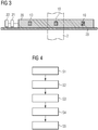
- FIG. 3 shows a schematic representation of a cross section through a current measuring device 1 according to one embodiment.
- the magnetic field sensors 10-i are arranged in the interior of the compensation coil 20.
- Compensation coil 20 and also the individual magnetic field sensors 10-i can be arranged on a suitable support 23.
- the control device 21 and the evaluation device 22 may be arranged on this carrier 23.
- the individual turns of the compensation coil 20 run as in FIG. 3 illustrated, so that the magnetic field due to an electric current through the current conductor 2 and the magnetic field due to the compensation current through the compensation coil 20 can compensate each other.
- FIG. 4 shows a schematic representation of a flowchart on which a method for determining an electric current in a current conductor according to an embodiment is based.
- a plurality of magnetic field sensors 10-i are provided, which are arranged around the current conductor 2.
- a compensation coil 20 is provided, which encloses the plurality of magnetic field sensors 10-i.
- step S3 the outputs provided by the magnetic field sensors can be detected.
- These output variables of the magnetic field sensors 10-i correspond to the magnetic fields detected by the respective magnetic field sensors 10-i.
- the output quantities U i can be a voltage that corresponds to the magnetic field detected by the magnetic field sensors.
- step S4 an electrical compensation current is then set in the compensation coil 20.
- the set compensation current through the compensation coil 20 is in this case based in particular on the output variables of the magnetic field sensors set.
- the compensation current is set by the compensation coil 20 such that the sum, in particular the weighted sum, of the output variables U i of the magnetic field sensors 10-i becomes minimal, preferably zero.
- the magnitude of the electric current through the current conductor 2 can be calculated based on the set compensation current through the compensation coil 20.
- the set compensation current can be multiplied by the compensation coil 20 with a known number n of turns of the compensation coil 20.
- the present invention relates to a current measuring device for the galvanically decoupled measurement of high currents through a conductor.
- a current measuring device for the galvanically decoupled measurement of high currents through a conductor.
- a plurality of magnetic field sensors is arranged around the current conductor.
- the current measuring device comprises a compensation coil, which encloses the magnetic field sensors, and in which a compensation current can be set.
- the compensation current through the compensation coil By adjusting the compensation current through the compensation coil, the magnetic field due to the electrical current to be measured by the current conductor and the magnetic field due to the electric compensation current through the compensation coil can compensate as much as possible. This allows a very precise and trouble-free measurement of high electrical currents over a wide dynamic range.
Landscapes
- Physics & Mathematics (AREA)
- General Physics & Mathematics (AREA)
- Engineering & Computer Science (AREA)
- Power Engineering (AREA)
- Condensed Matter Physics & Semiconductors (AREA)
- Measuring Instrument Details And Bridges, And Automatic Balancing Devices (AREA)
Description
- Die vorliegende Erfindung betrifft eine Strommessvorrichtung sowie ein Verfahren zur Bestimmung eines elektrischen Stroms in einem Stromleiter.
- Zahlreiche energietechnische Anwendungen erfordern die Messung von hohen elektrischen Strömen. Hierzu kann beispielsweise ein durch den elektrischen Strom hervorgerufenes Magnetfeld um einen elektrischen Leiter herum erfasst und ausgewertet werden. Aus einem solchen erfassten Magnetfeld kann eine Aussage über den elektrischen Strom getroffen werden, der durch den Leiter fließt. Hierzu kann beispielsweise auch ein elektrischer Leiter durch einen ringförmigen sogenannten Flusskonzentrator geführt werden. Ein solcher Flusskonzentrator besteht beispielsweise aus einem ferromagnetischen Material, wodurch sich die magnetischen Feldlinien um den stromführenden Leiter in diesem Flusskonzentrator konzentrieren. Das magnetische Feld in diesem Flusskonzentrator kann durch einen Magnetfeldsensor, wie zum Beispiel einen Hall-Sensor, in einem Spalt des Flusskonzentrators erfasst werden. Solche Flusskonzentratoren aus ferro- bzw. ferrimagnetischen Materialien bedingen jedoch ein relativ großes Gewicht des Sensors. Darüber hinaus kann es aufgrund der magnetischen Hysterese auch zu Messfehlern kommen.
- Stromsensoren nach dem Kompensationsprinzip sind aus
US3323056 ,US2010/259246 ,US5241263 ,DE102011110648 , und 'Analysis and Test of a Zero-Flux Current Sensor to Be Used in ITER', Yong et al, JOURNAL OF FUSION ENERGY, 2014, Vol. 34, No. 3, S. 463-468, XP035499053, bekannt. - Es besteht daher ein Bedarf nach einer Strommessvorrichtung, sowie einem Verfahren zur Messung eines elektrischen Stroms in einem Stromleiter, das eine präzise Strommessung in dem Stromleiter ermöglicht. Darüber hinaus besteht ein Bedarf nach einer Strommessung in einem Stromleiter mit einem möglichst großen Strommessbereich. Ferner besteht ein Bedarf nach einer Strommessung in einem elektrischen Leiter mit einer möglichst geringen Empfindlichkeit gegenüber Störfeldern.
- Hierzu schafft die vorliegende Erfindung gemäß einem Aspekt eine Strommessvorrichtung ohne Magnetfeldkonzentrator zur Bestimmung eines elektrischen Stroms in einem Stromleiter. Die Strommessvorrichtung umfasst eine Mehrzahl von Magnetfeldsensoren, die um den Stromleiter herum angeordnet sind. Die Mehrzahl von Magnetfeldsensoren sind dabei dazu ausgelegt, ein Magnetfeld zu erfassen und ein zu dem erfassten Magnetfeld korrespondierendes Ausgangssignal bereitzustellen. Ferner umfasst die Strommessvorrichtung eine Kompensationsspule, die um den Stromleiter herum angeordnet ist. Dabei ist die Mehrzahl von Magnetfeldsensoren im Inneren der Kompensationsspule angeordnet. Schließlich umfasst die Strommessvorrichtung weiterhin eine Regeleinrichtung, die dazu ausgelegt ist, einen elektrischen Kompensationsstrom in der Kompensationsspule einzustellen. Dabei wird kein Magnetfeldkonzentrator oder Flusskreis aus einem ferro- oder ferrimagnetischen Material eingesetzt.
- Gemäß einem weiteren Aspekt schafft die vorliegende Erfindung ein Verfahren zur Bestimmung eines elektrischen Stroms in einem Stromleiter ohne Magnetfeldkonzentrator. Das Verfahren umfasst die Schritte des Bereitstellens einer Mehrzahl von Magnetfeldsensoren um den Stromleiter und des Bereitstellens einer Kompensationsspule, die die Mehrzahl von Magnetfeldsensoren umschließt. Das Verfahren umfasst ferner die Schritte des Erfassens der von den Magnetfeldsensoren bereitgestellten Ausgangsgrößen, des Einstellens eines elektrischen Kompensationsstroms in der Kompensationsspule basierend auf den erfassten Ausgangsgrößen der Magnetfeldsensoren; und des Bestimmens der Größe eines elektrischen Stroms durch den Stromleiter basierend auf dem eingestellten Kompensationsstrom durch die Kompensationsspule. Dabei wird kein Magnetfeldkonzentrator oder Flusskreis aus einem ferro- oder ferrimagnetischen Material eingesetzt.
- Der vorliegenden Erfindung liegt die Idee zugrunde, das Magnetfeld eines von einem elektrischen Strom durchflossenen Stromleiters mittels einer Mehrzahl von Magnetfeldsensoren um den Stromleiter herum zu erfassen. Dabei wird gleichzeitig in einer Kompensationsspule ein elektrischer Strom eingestellt, um das von dem Stromleiter hervorgerufene erfasste Magnetfeld zu kompensieren. Durch diese Kompensation ist eine sehr genaue Bestimmung des elektrischen Stroms durch den Stromleiter möglich.
- Aufgrund des Kompensationsprinzips muss unabhängig von dem elektrischen Strom durch den Stromleiter durch die Magnetfeldsensoren jeweils nur ein relativ geringes Magnetfeld erfasst werden. Daher ist die Strommessung über einen sehr großen Messbereich hinweg möglich.
- Im Gegensatz zu konventionellen Strommesswandlern mit einem Magnetfeldkonzentrator ist bei dem erfindungsgemäßen Messprinzip kein Flusskreis aus einem ferro- oder ferrimagnetischen Material erforderlich. Somit sind auch keine Messfehler aufgrund der magnetischen Hysterese in dem Flusskonzentrator zu erwarten. Darüber hinaus sinkt auch das Gewicht der Strommessvorrichtung im Vergleich zu konventionellen Strommessvorrichtungen mit Flusskonzentratoren.
- Aufgrund der Verwendung von mehreren Magnetfeldsensoren um den Stromleiter herum gleichen sich auch gegebenenfalls statistische Offset-Fehler besser aus, wodurch die Genauigkeit der Strommessvorrichtung zusätzlich gesteigert werden kann.
- Da sich im Inneren der Kompensationsspule bis auf die Magnetfeldsensoren in der Regel nur dia- oder paramagnetisches Material befindet, weist die Kompensationsspule auch eine sehr geringe Induktivität auf. Dies führt auch zu einer sehr großen Grenzfrequenz einer Kompensationsregelung für das Einstellen des Stroms durch die Kompensationsspule. Für die Treiber des Stroms durch die Kompensationsspule ist somit ein relativ einfacher Aufbau möglich.
- Schließlich weist der erfindungsgemäße Aufbau der Strommessvorrichtung eine sehr geringe Empfindlichkeit gegenüber Fremd- und Störfeldern auf.
- In einer Ausführungsform der Strommessvorrichtung ist die Mehrzahl von Magnetfeldsensoren in einer Ebene angeordnet, wobei diese Ebene senkrecht zur Stromflussrichtung durch den Stromleiter verläuft.
- Gemäß einer weiteren Ausführungsform ist jedem Magnetfeldsensor der Mehrzahl von Magnetfeldsensoren ein Flächensegment der Ebene zugeordnet. Dabei wird das jeweilige von dem Magnetfeldsensor bereitgestellte Ausgangssignal mit einem Gewichtungsfaktor gewichtete, der zu der Fläche des korrespondierenden Flächensegments korrespondiert. Auf diese Weise kann auch bei nicht gleichförmig um den Stromleiter verteilten Magnetfeldsensoren eine korrekte Erfassung des durch den Stromfluss hervorgerufenen Magnetfelds um den Stromleiter erfolgen.
- Gemäß einer weiteren Ausführungsform weisen alle Magnetfeldsensoren der Mehrzahl von Magnetfeldsensoren den gleichen Abstand zu einer Mittelachse des Stromleiters auf.
- Gemäß einer weiteren Ausführungsform sind die Magnetfeldsensoren äquidistant um den Stromleiter herum angeordnet.
- Gemäß einer weiteren Ausführungsform stellt die Regeleinrichtung den elektrischen Kompensationsstrom in der Kompensationsspule basierend auf den von der Mehrzahl von Magnetfeldsensoren bereitgestellten Ausgangsignalen ein.
- Gemäß einer weiteren Ausführungsform stellt die Regeleinrichtung den Kompensationsstrom in der Kompensationsspule so ein, dass die Summe der von der Mehrzahl von Magnetfeldsensoren bereitgestellten Ausgangssignale Null wird. Werden die Ausgangssignale von den einzelnen Magnetfeldsensoren dabei unterschiedlich gewichtet, so stellt die Regeleinrichtung den Kompensationsstrom in der Kompensationsspule so ein, dass die gewichtete Summe der Ausgangssignale Null wird. Auf diese Weise ist das von den Magnetfeldsensoren zu erfassende Magnetfeld minimal, so dass eine besonders präzise Messung möglich wird.
- Gemäß einer weiteren Ausführungsform weist die Kompensationsspule eine Torus-förmige Außengeometrie auf.
- Gemäß einer weiteren Ausführungsform umfasst die Mehrzahl von Magnetfeldsensoren magneto-resistive (MR) Magnetfeldsensoren. Solche Magnetfeldsensoren, die nach dem magneto-resistiven Messprinzip arbeiten, ermöglichen eine sehr genaue und präzise Messung von Magnetfeldern bei kleiner, leichter und kompakter Bauweise.
- Gemäß einer weiteren Ausführungsform umfasst die Strommessvorrichtung eine Auswerteeinrichtung, die dazu ausgelegt ist, den elektrischen Strom durch den Stromleiter basierend auf dem elektrischen Strom zu ermitteln, der durch die Kompensationsspule fließt.
- Gemäß einer weiteren Ausführungsform wird der elektrische Strom, insbesondere der elektrische Strom, der durch die Auswerteeinrichtung bestimmt wird, aus dem Produkt des elektrischen Stroms durch die Kompensationsspule und einer Anzahl der Windungen der Kompensationsspule berechnet. Auf diese Weise kann der Strom durch den Stromleiter sehr einfach berechnet werden.
- Gemäß einer weiteren Ausführungsform des Verfahrens zum Messen eines elektrischen Stroms in einem Stromleiter minimiert der Schritt zum Einstellen des elektrischen Kompensationsstroms durch die Kompensationsspule die Ausgangsgrößen der Magnetfeldsensoren. Insbesondere wird in dem Schritt zum Einstellen des elektrischen Kompensationsstroms der Strom so eingestellt, dass die Summe, insbesondere eine gegebenenfalls gewichtete Summe, der Ausgangsgrößen der Magnetfeldsensoren minimal wird.
- Gemäß einer weiteren Ausführungsform werden in dem Schritt zum Einstellen des elektrischen Kompensationsstroms in der Kompensationsspule die Ausgangsgrößen der Mehrzahl von Magnetfeldsensoren mit einem Gewichtungsfaktor multipliziert. Dieser Gewichtungsfaktor kann sich dabei insbesondere aus einem Flächensegment ergeben, der dem jeweiligen Magnetfeldsensor zugeordnet ist.
- Gemäß einer weiteren Ausführungsform wird in dem Schritt zum Bestimmen der Größe des elektrischen Stroms durch den Stromleiter der elektrische Strom aus einem Produkt des Kompensationsstroms durch die Kompensationsspule und eine Anzahl der Windungen der Kompensationsspule berechnet.
- Weitere Ausführungsformen und Vorteile der vorliegenden Erfindung ergeben sich aus der nachfolgenden Beschreibung unter Bezug auf die beigefügten Zeichnungen. Dabei zeigen:
- Figur 1:
- eine schematische Darstellung einer Strommessvorrichtung mit einer Mehrzahl von Magnetfeldsensoren um einen Stromleiter;
- Figur 2:
- eine schematische Darstellung einer Strommessvorrichtung gemäß einer Ausführungsform;
- Figur 3:
- eine schematische Darstellung eines Querschnitts durch eine Strommessvorrichtung gemäß einer Ausführungsform; und
- Figur 4:
- eine schematische Darstellung eines Ablaufdiagramms, wie es einem Verfahren zur Messung eines elektrischen Stroms durch einen Stromleiter zugrundeliegt.
-
Figur 1 zeigt eine schematische Darstellung eines Hochstromsensors. Dabei sind in dieser Darstellung sechs Magnetfeldsensoren 10-i um einen Stromleiter 2 herum angeordnet. Die Magnetfeldsensoren 10-i können dabei auf einem hier nicht dargestellten Trägermaterial angeordnet werden. Wird der Stromleiter 2 von einem elektrischen Strom durchflossen, so wird hierdurch ein magnetisches Feld um den Stromleiter 2 herum hervorgerufen. Dieses Magnetfeld kann von den Magnetfeldsensoren 10-i erfasst werden. Dabei wird durch die einzelnen Magnetfeldsensoren 10-i lokal (punktweise) jeweils die Tangentialkomponente des Magnetfelds gemessen. Anschließend kann durch Summation dieser Tangentialkomponenten gemäß der folgenden Formel auf den Strom IL in dem elektrischen Leiter geschlossen werden:
- Dabei ist Ui die Sensorausgangsspannung des jeweiligen Magnetfeldsensors 10-i, ai die Empfindlichkeit des jeweiligen Magnetfeldsensors 10-i, Δsi ein Streckenabschnitt im i-ten Intervall auf einer Kurve um den Stromleiter 2, auf dem die Magnetfeldsensoren 10-i liegen.
- Für einen möglichst einfachen und kostengünstigen Stromsensor sollte dabei das Magnetfeld um den Stromleiter 2 mit möglichst wenigen Stützstellen, das heißt möglichst wenigen Magnetfeldsensoren 10-i angenähert werden. Damit dieses Ziel erreicht werden kann, bietet sich eine Geometrie für die Randkurve, auf der die Messung erfolgt, an, die die räumliche Anordnung des Messstroms und der Störströme gut berücksichtigt. Damit kommen als Randkurven insbesondere Kreise, Ellipsen, gleichseitige Vielecke, wie zum Beispiel Pentagone, Hexagone etc. in Frage. Wichtig für die Feststellung der Kurvenform ist dabei insbesondere, dass unter allen erdenklichen Betriebszuständen möglichst alle Sensoren in ihrer sensitiven Richtung immer eine ähnliche magnetische Feldstärke sehen und keine punktuelle Übersteuerung von Einzelkomponenten das Ergebnis verfälscht.
- Bei einer einfachen Zylindergeometrie eines geraden langgestreckten Leiters 2 mit kreisförmigem Querschnitt ist dabei eine kreisförmige Anordnung der Magnetfeldsensoren 10-i mit dem stromführenden Leiter 2 im Mittelpunkt eine für die praktische Umsetzung vorteilhafte Variante, wie diese in
Figur 1 dargestellt ist. Bei der Diskretisierung der Randkurve bietet es sich an, die Magnetfeldsensoren 10-i möglichst äquidistant und mit gleichem Abstand zum Mittelpunkt des elektrischen Leiters 2 anzuordnen. Bereiche der Randkurve mit hoher Krümmung bzw. einem hohen Störeinfluss können dabei bei einer Diskretisierung der Randkurve höher aufgelöst werden, das heißt in diesem Bereich kann eine größere Anzahl von Magnetfeldsensoren 10-i angeordnet werden. - Insbesondere ist anzumerken, dass die hier gewählte Anzahl von sechs Magnetfeldsensoren 10-i um den Stromleiter 2 herum nur beliebiges Beispiel darstellt. Je nach Anwendungsgebiet können auch mehr oder weniger Magnetfeldsensoren 10-i für einen Stromsensor gewählt werden.
-
Figur 2 zeigt eine schematische Darstellung einer Strommessvorrichtung 1 mit dem zuvor beschriebenen Messprinzip gemäß einer Ausführungsform. Die Strommessvorrichtung 1 umfasst dabei eine Mehrzahl von Magnetfeldsensoren 10-i, eine Kompensationsspule 20, sowie eine Regeleinrichtung 21. Beispielsweise kann es sich bei den Magnetfeldsensoren um magneto-resistive Magnetfeldsensoren handeln. - Für die Anordnung der Magnetfeldsensoren 10-i um den Stromleiter 2 gelten auch hier die Ausführungen, wie sie oben im Zusammenhang mit
Figur 1 bereits erläutert wurden. Die Mehrzahl von Magnetfeldsensoren 10-i sind also entlang eines Kurvenverlaufs um den Stromleiter 2 herum angeordnet. In einer Ausführungsform können die Magnetfeldsensoren 10-i alle gleich weit von der Mittelachse des Stromleiters 2 beabstandet sein. Auch ist es möglich, dass alle Magnetfeldsensoren 10-i äquidistant beabstandet sind. Je nach Anwendungsfall, insbesondere von eventuell auftretenden Störeinflüssen oder einem starken Krümmungsradius, etc. kann jedoch auch eine andere Anordnung der Magnetfeldsensoren 10-i vorteilhaft sein. Die Magnetfeldsensoren 10-i sind dabei vorzugsweise auf einer (virtuellen) Ebene angeordnet, die senkrecht zu der Stromflussrichtung durch den Stromleiter 2 verläuft. Insbesondere bei einer nicht-äquidistanten bzw. ungleichförmigen Anordnung der Magnetfeldsensoren 10-i um den Stromleiter 2 herum kann dabei jedem Magnetfeldsensor 10-i ein Gewichtungsfaktor ai zugeordnet werden. Dieser Gewichtungsfaktor ai kann dabei zu einem Flächensegment korrespondieren, das dem jeweiligen Magnetfeldsensor 10-i in der (virtuellen) Ebene entspricht. - Jeder der Magnetfeldsensoren 10-i liefert dabei ein Ausgangssignal, beispielsweise eine Ausgangsspannung Ui, die einem von dem jeweiligen Magnetfeldsensor 10-i erfassten Magnetfeld entspricht. Alle diese Ausgangssignale (Ausgangsspannungen) Ui können der Regeleinrichtung 21 zugeführt werden.
- Abweichend von dem Aufbau gemäß
Figur 1 weist die Strommessvorrichtung 1 weiterhin eine Kompensationsspule 20 auf. Diese Kompensationsspule 20 ist ebenfalls um den Stromleiter 2 herum angeordnet. Die Magnetfeldsensoren 10-i der Strommessvorrichtung 1 sind dabei im Inneren der Kompensationsspule 20 angeordnet. Die Kompensationsspule 20 weist dabei eine vorgegebene Anzahl n von Windungen auf. - Bei einer möglichen Ausführungsform handelt es sich bei der Kompensationsspule 20 um eine ringförmige Spule. Diese ringförmige Spule kann die Form eines Torus aufweisen. Aber auch andere Spulengeometrien zur Kompensation des Magnetfelds, das durch den elektrischen Strom durch den Stromleiter 20 hervorgerufen wird, sind möglich.
- Die Kompensationsspule 20 ist mit der Regeleinrichtung 21 gekoppelt. Somit kann die Regeleinrichtung 21 einen elektrischen Strom in die Kompensationsspule 20 einspeisen. Durch den Kompensationsstrom in der Kompensationsspule 20 wird innerhalb der Kompensationsspule 20, also in dem Raum, in dem sich auch die Magnetfeldsensoren 10-i befinden, ein Magnetfeld hervorgerufen. Dieses Magnetfeld innerhalb der Kompensationsspule 20, das durch den Kompensationsstrom hervorgerufen wird, wirkt dabei dem Magnetfeld entgegen, das aufgrund des elektrischen Stroms durch den Stromleiter 2 verursacht wird. Auf diese Weise können sich das Magnetfeld aufgrund des elektrischen Stroms durch den Stromleiter 2 und das Magnetfeld aufgrund des Kompensationsstromes in der Kompensationsspule 20 im günstigsten Fall gegenseitig vollständig kompensieren. Hierzu kann die Regeleinrichtung 21 die Ausgangssignale Ui der Magnetfeldsensoren 10-i auswerten, und den Kompensationsstrom durch die Kompensationsspule 20 so einstellen, dass die Ausgangssignale Ui der Magnetfeldsensoren 10-i minimal werden. Hierzu betrachtet die Regeleinrichtung 21 vorzugsweise die Summe aller Ausgangssignale Ui der einzelnen Magnetfeldsensoren 10-i. Werden die einzelnen Ausgangssignale Ui der Magnetfeldsensoren 10-i dabei unterschiedlich gewichtet, so kann die Regeleinrichtung 21 auch die entsprechend gewichtete Summe der Ausgangssignale Ui für das Regeln des Kompensationsstromes durch die Kompensationsspule 20 berücksichtigen.
- Vorzugsweise regelt die Regeleinrichtung 21 den Kompensationsstrom durch die Kompensationsspule 20 so ein, dass die (gewichtete) Summe der Ausgangssignale Ui der Magnetfeldsensoren 10-i minimal, insbesondere möglichst Null wird. Hierzu ist es durchaus möglich, dass einzelne Magnetfeldsensoren 10-i jeweils ein von Null verschiedenes Ausgangssignal Ui ausgeben und dennoch die (gewichtete) Summe aller Ausgangssignale nach Einregeln des Kompensationsstromes durch die Kompensationsspule 20 zu Null wird.
- Da sich das Magnetfeld aufgrund des elektrischen Stroms durch den Stromleiter 2 und das Magnetfeld aufgrund des Kompensationsstroms durch die Kompensationsspule 20 gegenseitig abschwächen und im günstigsten Falle vollständig kompensieren, müssen die Magnetfeldsensoren 10-i nur ein relativ geringes Magnetfeld erfassen. Ein steigender Strom durch den Stromleiter 2 kann durch Erhöhen des Kompensationsstroms durch die Kompensationsspule 2 ausgeglichen werden. Auf diese Weise ist es möglich, mit der beschriebenen Strommessvorrichtung 1 elektrische Ströme durch den Stromleiter 2 über einen großen Messbereich hinweg sehr präzise zu erfassen. Insbesondere ist eine Messung von elektrischen Strömen zwischen 40 A und 100 A sehr gut möglich. Aber auch geringere oder höhere Ströme können mit der Strommessvorrichtung 1 bei entsprechender Kompensation des Magnetfelds durch die Kompensationsspule 2 sehr gut erfasst und gemessen werden.
- Die Regeleinrichtung 21 erfasst dabei, wie zuvor bereits beschrieben, die (gewichtete) Summe aller Ausgangssignale Ui der Magnetfeldsensoren 10-i und regelt daraufhin den Kompensationsstrom durch die Kompensationsspule 20 so ein, dass die (gewichtete) Summe der Ausgangssignale Ui der Magnetfeldsensoren 10-i minimal, bestenfalls Null wird. In diesem Fall kann der elektrische Strom durch den Stromleiter 2 sehr einfach aus dem Produkt der Windungszahl n der Kompensationsspule 20 und dem eingestellten Kompensationsstrom Ik berechnet werden. Hierzu kann die Strommessvorrichtung 1 ferner eine Auswerteeinrichtung 22 umfassen, die basierend auf dem elektrischen Kompensationsstrom durch die Kompensationsspule 20 den elektrischen Strom durch den Stromleiter 2 bestimmt. Insbesondere kann die Auswerteeinrichtung 22 bei einer bekannten Anzahl n von Windungen der Kompensationsspule 20 durch Messung des Kompensationsstroms durch die Kompensationsspule 20 den Strom durch den elektrischen Leiter 2 aus dem Produkt des Kompensationsstroms durch die Kompensationsspule 20 und der Windungsanzahl n der Kompensationsspule berechnen. Anschließend kann die Auswerteeinrichtung 22 ein analoges oder digitales Ausgangssignal bereitstellen, das zu dem ermittelten elektrischen Strom durch den Stromleiter 2 korrespondiert.
-
Figur 3 zeigt eine schematische Darstellung eines Querschnitts durch eine Strommessvorrichtung 1 gemäß einer Ausführungsform. Wie dabei zu erkennen ist, sind die Magnetfeldsensoren 10-i im Inneren der Kompensationsspule 20 angeordnet. Kompensationsspule 20 und auch die einzelnen Magnetfeldsensoren 10-i können dabei auf einem geeigneten Träger 23 angeordnet sein. Auch die Regeleinrichtung 21 und die Auswerteeinrichtung 22 können auf diesem Träger 23 angeordnet sein. Die einzelnen Windungen der Kompensationsspule 20 verlaufen dabei, wie inFigur 3 dargestellt, so, dass sich das Magnetfeld aufgrund eines elektrischen Stroms durch den Stromleiter 2 und das Magnetfeld aufgrund des Kompensationsstroms durch die Kompensationsspule 20 gegenseitig kompensieren können. -
Figur 4 zeigt eine schematische Darstellung eines Ablaufdiagramms, wie es einem Verfahren zur Bestimmung eines elektrischen Stroms in einem Stromleiter gemäß einer Ausführungsform zugrunde liegt. Zunächst wird in einem Schritt S1 eine Mehrzahl von Magnetfeldsensoren 10-i bereitgestellt, die um den Stromleiter 2 angeordnet sind. Weiterhin wird in Schritt S2 eine Kompensationsspule 20 bereitgestellt, die die Mehrzahl von Magnetfeldsensoren 10-i umschließt. - Daraufhin können in Schritt S3 die von den Magnetfeldsensoren bereitgestellten Ausgangsgrößen erfasst werden. Diese Ausgangsgrößen der Magnetfeldsensoren 10-i korrespondieren dabei zu dem von den jeweiligen Magnetfeldsensoren 10-i erfassten Magnetfeldern. Insbesondere kann es sich bei den Ausgangsgrößen Ui um eine Spannung handeln, die zu dem von den Magnetfeldsensoren erfassten Magnetfeld korrespondiert.
- In Schritt S4 wird daraufhin in der Kompensationsspule 20 ein elektrischer Kompensationsstrom eingestellt. Der eingestellte Kompensationsstrom durch die Kompensationsspule 20 wird dabei insbesondere basierend auf den Ausgangsgrößen der Magnetfeldsensoren eingestellt. Insbesondere wird der Kompensationsstrom durch die Kompensationsspule 20 so eingestellt, dass die Summe, insbesondere die gewichtete Summe, der Ausgangsgrößen Ui der Magnetfeldsensoren 10-i minimal, vorzugsweise Null wird. Daraufhin kann in Schritt S5 die Größe des elektrischen Stroms durch den Stromleiter 2 basierend auf dem eingestellten Kompensationsstrom durch die Kompensationsspule 20 berechnet werden. Hierzu kann beispielsweise der eingestellte Kompensationsstrom durch die Kompensationsspule 20 mit einer bekannten Anzahl n von Windungen der Kompensationsspule 20 multipliziert werden.
- Zusammenfassend betrifft die vorliegende Erfindung eine Strommessvorrichtung zur galvanisch entkoppelten Messung von hohen Strömen durch einen Stromleiter. Hierzu wird um den Stromleiter eine Mehrzahl von Magnetfeldsensoren angeordnet. Ferner umfasst die Strommessvorrichtung eine Kompensationsspule, die die Magnetfeldsensoren umschließt, und in der ein Kompensationsstrom eingestellt werden kann. Durch Einregeln des Kompensationsstroms durch die Kompensationsspule können sich das Magnetfeld aufgrund des zu messenden elektrischen Stroms durch den Stromleiter und des Magnetfelds aufgrund des elektrischen Kompensationsstroms durch die Kompensationsspule weitestgehend kompensieren. Dies ermöglicht eine sehr präzise und störungsfreie Messung von hohen elektrischen Strömen über einen großen Dynamikbereich hinweg.
Claims (15)
- Strommessvorrichtung (1) ohne Magnetfeldkonzentrator zur Bestimmung eines elektrischen Stroms in einem Stromleiter (2), mit:einer Mehrzahl von Magnetfeldsensoren (10-i), die um den Stromleiter (2) angeordnet sind, und die dazu ausgelegt sind ein zu einem erfassten Magnetfeld korrespondierendes Ausgangsignal bereitzustellen;einer Kompensationsspule (20), die um den Stromleiter (2) angeordnet ist, wobei die Mehrzahl von Magnetfeldsensoren (10-i) im Inneren der Kompensationsspule (20) angeordnet sind; undeiner Regeleinrichtung (21), die dazu ausgelegt ist, einen elektrischen Kompensationsstrom in der Kompensationsspule (20) einzustellen,wobei kein Magnetfeldkonzentrator oder Flusskreis aus einem ferro- oder ferrimagnetischen Material eingesetzt wird.
- Strommessvorrichtung (1) nach Anspruch 1, wobei die Mehrzahl von Magnetfeldsensoren (10-i) in einer Ebene angeordnet ist, die senkrecht zur Stromflussrichtung durch den Stromleiter (2) verläuft.
- Strommessvorrichtung (1) nach Anspruch 2, wobei jedem Magnetfeldsensor (10-i) der Mehrzahl von Magnetfeldsensoren (10-i) ein Flächensegment der Ebene zugeordnet ist, und das von dem jeweiligen Magnetfeldsensor (10-i) bereitgestellte Ausgangssignal mit einem zu der Fläche des korrespondierenden Flächensegments Gewichtungsfaktor gewichtet wird.
- Strommessvorrichtung (1) nach einem der Ansprüche 1 bis 3, wobei alle Magnetfeldsensoren (10-i) der Mehrzahl von Magnetfeldsensoren (10-i) den gleichen Abstand zu einer Mittelachse des Stromleiters (2) aufweisen.
- Strommessvorrichtung (1) nach einem der Ansprüche 1 bis 4, wobei die Magnetfeldsensoren (10-i) äquidistant um den Stromleiter (2) angeordnet sind.
- Strommessvorrichtung (1) nach einem der Ansprüche 1 bis 5, wobei die Regeleinrichtung (21) den elektrischen Kompensationsstrom in der Kompensationsspule (20) basierend auf den von der Mehrzahl von Magnetfeldsensoren (10-i) bereitgestellten Ausgangsignalen einstellt.
- Strommessvorrichtung (1) nach einem der Ansprüche 1 bis 6, wobei die Regeleinrichtung (21) den Kompensationsstrom in der Kompensationsspule (20) so einstellt, dass die Summe der von der Mehrzahl von Magnetfeldsensoren (10-i) bereitgestellten Ausgangssignale Null wird.
- Strommessvorrichtung (1) nach einem der Ansprüche 1 bis 7, wobei die Kompensationsspule (20) eine Torus-förmige Außengeometrie aufweist.
- Strommessvorrichtung (1) nach einem der Ansprüche 1 bis 8, wobei die Mehrzahl von Magnetfeldsensoren (10-i) magneto-resistive Magnetfeldsensoren umfassen.
- Strommessvorrichtung (1) nach einem der Ansprüche 1 bis 9, ferner umfassend eine Auswerteeinrichtung (22), die dazu ausgelegt ist, den elektrischen Strom durch den Stromleiter (2) basierend auf dem elektrischen Strom zu ermitteln, der durch die Kompensationsspule (20) fließt.
- Strommessvorrichtung (1) nach Anspruch 10, wobei der elektrische Strom durch den Stromleiter sich aus dem Produkt des elektrischen Stroms durch die Kompensationsspule und der (einer) Anzahl der Windungen der Kompensationsspule ergibt.
- Verfahren zum Bestimmung eines elektrischen Stroms in einem Stromleiter (2) ohne Magnetfeldkonzentrator, mit den Schritten:Bereitstellen (S1) einer Mehrzahl von Magnetfeldsensoren (10-i) um den Stromleiter (2);Bereitstellen (S2) einer Kompensationsspule (20), die die Mehrzahl von Magnetfeldsensoren (10-i) umschließt;Erfassen (S3) der von den Magnetfeldsensoren (10-i) bereitgestellten Ausgangsgrößen;Einstellen (S4) eines elektrischen Kompensationsstroms in der Kompensationsspule (20) basierend auf den erfassten Ausgangsgrößen der Magnetfeldsensoren (10-i);Bestimmen (S5) der Größe eines elektrischen Stroms durch den Stromleiter (2) basierend auf dem eingestellten Kompensationsstrom durch die Kompensationsspule (20),wobei kein Magnetfeldkonzentrator oder Flusskreis aus einem ferro- oder ferrimagnetischen Material eingesetzt wird.
- Verfahren nach Anspruch 12, wobei der Schritt (S4) zum Einstellen des elektrischen Kompensationsstroms durch die Kompensationsspule (20) die Ausgangsgrößen der Magnetfeldsensoren (10-i) minimiert.
- Verfahren nach Anspruch 12 oder 13, wobei der Schritt zum Einstellen (S4) des elektrischen Kompensationsstroms die die Ausgangsgrößen der Mehrzahl von Magnetfeldsensoren (10-i) mit einem Gewichtungsfaktor multipliziert.
- Verfahren nach einem der Ansprüche 12 bis 14, wobei der Schritt (S5) zum Bestimmen der Größe des elektrischen Stroms durch den Stromleiter (2) den elektrischen Strom aus einem Produkt des Kompensationsstroms durch die Kompensationsspule (20) und einer Anzahl der Windungen der Kompensationsspule (20) berechnet.
Applications Claiming Priority (2)
| Application Number | Priority Date | Filing Date | Title |
|---|---|---|---|
| DE102015205794.1A DE102015205794A1 (de) | 2015-03-31 | 2015-03-31 | Strommessvorrichtung und Verfahren zur Bestimmung eines elektrischen Stroms |
| PCT/EP2016/056914 WO2016156392A1 (de) | 2015-03-31 | 2016-03-30 | Strommessvorrichtung und verfahren zur bestimmung eines elektrischen stroms |
Publications (2)
| Publication Number | Publication Date |
|---|---|
| EP3259603A1 EP3259603A1 (de) | 2017-12-27 |
| EP3259603B1 true EP3259603B1 (de) | 2019-06-19 |
Family
ID=55650408
Family Applications (1)
| Application Number | Title | Priority Date | Filing Date |
|---|---|---|---|
| EP16713866.8A Active EP3259603B1 (de) | 2015-03-31 | 2016-03-30 | Strommessvorrichtung und verfahren zur bestimmung eines elektrischen stroms |
Country Status (6)
| Country | Link |
|---|---|
| US (1) | US10393775B2 (de) |
| EP (1) | EP3259603B1 (de) |
| CN (1) | CN107567589B (de) |
| DE (1) | DE102015205794A1 (de) |
| DK (1) | DK3259603T3 (de) |
| WO (1) | WO2016156392A1 (de) |
Families Citing this family (13)
| Publication number | Priority date | Publication date | Assignee | Title |
|---|---|---|---|---|
| DE102015205794A1 (de) | 2015-03-31 | 2016-10-06 | Siemens Aktiengesellschaft | Strommessvorrichtung und Verfahren zur Bestimmung eines elektrischen Stroms |
| EP3534538A1 (de) * | 2018-02-28 | 2019-09-04 | LEM Intellectual Property SA | Elektronisches leistungsschalterantriebsmodul |
| EP3543715B1 (de) * | 2018-03-22 | 2023-01-25 | ABB Schweiz AG | Vorrichtung zur messung von elektrischem strom |
| US10712369B2 (en) * | 2018-03-23 | 2020-07-14 | Analog Devices Global Unlimted Company | Current measurement using magnetic sensors and contour intervals |
| EP3561524A1 (de) | 2018-04-25 | 2019-10-30 | Siemens Aktiengesellschaft | Strommessvorrichtung mit flexibler leiterplatte |
| DE102018111011A1 (de) | 2018-05-08 | 2019-11-14 | Infineon Technologies Ag | Magnetfeldsensorvorrichtung |
| EP3671226A1 (de) | 2018-12-18 | 2020-06-24 | Siemens Aktiengesellschaft | Strommessvorrichtung zur messung eines elektrischen stroms in einem leiter |
| CN110146737A (zh) * | 2019-05-28 | 2019-08-20 | 杭州电子科技大学 | 一种基于磁分流结构的大量程电流传感器 |
| CN115461971A (zh) * | 2020-05-15 | 2022-12-09 | 雅马哈发动机株式会社 | 输送装置及输送方法 |
| CN112382479B (zh) * | 2020-10-21 | 2022-09-23 | 惠州市明大精密电子有限公司 | 一种工字电感及其制作方法 |
| CN112213679B (zh) * | 2020-10-22 | 2022-11-08 | 国网福建省电力有限公司 | 基于位置信息的磁敏电流互感器估值方法 |
| CN113358916A (zh) * | 2021-07-27 | 2021-09-07 | 国仪量子(合肥)技术有限公司 | 电流检测系统及方法 |
| JP2024008304A (ja) * | 2022-07-07 | 2024-01-19 | 横河電機株式会社 | 電流センサ |
Citations (1)
| Publication number | Priority date | Publication date | Assignee | Title |
|---|---|---|---|---|
| DE102011110648A1 (de) * | 2011-08-18 | 2013-02-21 | Universität Stuttgart | Strommessgerät |
Family Cites Families (10)
| Publication number | Priority date | Publication date | Assignee | Title |
|---|---|---|---|---|
| BE650176A (de) * | 1963-07-05 | |||
| DE3705450A1 (de) * | 1987-02-20 | 1988-09-01 | Vacuumschmelze Gmbh | Stromwandler zur messung von rechteckstroemen nach dem kompensationsprinzip |
| JPH04252934A (ja) * | 1991-01-29 | 1992-09-08 | Sanki Eng Kk | 多向流式遠心連続多段抽出装置 |
| US7164263B2 (en) * | 2004-01-16 | 2007-01-16 | Fieldmetrics, Inc. | Current sensor |
| DE102006034579A1 (de) * | 2006-07-26 | 2008-01-31 | Siemens Ag | Stromerfassungsvorrichtung und Verfahren zur Stromerfassung |
| KR100877450B1 (ko) * | 2007-10-10 | 2009-01-07 | 김장수 | 관통구 개폐구조를 갖는 폐회로 전류변성기 |
| US8593133B2 (en) | 2010-12-29 | 2013-11-26 | General Electric Company | Current measuring systems and methods of assembling the same |
| DE102013100246A1 (de) * | 2013-01-11 | 2014-07-17 | Refusol Gmbh | Stromsensor- und Entstörfilteranordnung, insbesondere für transformatorlose Photovoltaik-Wechselrichter |
| DE102015205794A1 (de) | 2015-03-31 | 2016-10-06 | Siemens Aktiengesellschaft | Strommessvorrichtung und Verfahren zur Bestimmung eines elektrischen Stroms |
| TWI561830B (en) * | 2015-07-21 | 2016-12-11 | Ind Tech Res Inst | Non-contact type three-phase three-wire power cable measurement device and measurement method thereof |
-
2015
- 2015-03-31 DE DE102015205794.1A patent/DE102015205794A1/de not_active Withdrawn
-
2016
- 2016-03-30 WO PCT/EP2016/056914 patent/WO2016156392A1/de active Application Filing
- 2016-03-30 EP EP16713866.8A patent/EP3259603B1/de active Active
- 2016-03-30 US US15/563,735 patent/US10393775B2/en active Active
- 2016-03-30 CN CN201680025650.9A patent/CN107567589B/zh active Active
- 2016-03-30 DK DK16713866.8T patent/DK3259603T3/da active
Patent Citations (1)
| Publication number | Priority date | Publication date | Assignee | Title |
|---|---|---|---|---|
| DE102011110648A1 (de) * | 2011-08-18 | 2013-02-21 | Universität Stuttgart | Strommessgerät |
Also Published As
| Publication number | Publication date |
|---|---|
| DK3259603T3 (da) | 2019-09-09 |
| CN107567589B (zh) | 2020-09-11 |
| DE102015205794A1 (de) | 2016-10-06 |
| US20180095112A1 (en) | 2018-04-05 |
| WO2016156392A1 (de) | 2016-10-06 |
| CN107567589A (zh) | 2018-01-09 |
| EP3259603A1 (de) | 2017-12-27 |
| US10393775B2 (en) | 2019-08-27 |
Similar Documents
| Publication | Publication Date | Title |
|---|---|---|
| EP3259603B1 (de) | Strommessvorrichtung und verfahren zur bestimmung eines elektrischen stroms | |
| EP1839984B1 (de) | Kraftmessvorrichtung für Fahrzeugfahrwerke | |
| EP1726967B1 (de) | Verfahren und Vorrichtung zur Messung eines in einem elektrischen Leiter fliessenden Stroms | |
| DE102013005939A1 (de) | Messwiderstand und entsprechendes Messverfahren | |
| EP3589961B1 (de) | Verfahren zur strommessung und strommessvorrichtung | |
| EP2490037B1 (de) | Kalibrierbarer Magnetfeldsensor und Verfahren zur Herstellung desselben | |
| EP3631394B1 (de) | Vorrichtung, anordnung und verfahren zum charakterisieren der torsion, der rotation und/oder der positionierung einer welle | |
| DE4434417A1 (de) | Meßanordnung zur Messung eines elektrischen Stromes | |
| EP2615472B1 (de) | Einrichtung und Verfahren zur Überwachung eines Stromes eines Leitungsabschnitts | |
| DE102019102567B3 (de) | Sensorvorrichtung zur Messung von Gleich- und Wechselströmen | |
| EP2174147B1 (de) | Anordnung zur messung eines in einem elektrischen leiter fliessenden stroms | |
| EP2153237B1 (de) | Anordnung zur messung eines in einem elektrischen leiter fliessenden stroms | |
| DE102017203535A1 (de) | Stromsensor mit optimierter Stromdichteverteilung, Verfahren zum Bestimmen eines Laststroms | |
| EP2697659B1 (de) | Vorrichtung zur berührungslosen bestimmung eines elektrischen potentials eines objekts, stromzange sowie verfahren | |
| DE102015210426A1 (de) | Anordnung und Verfahren zum Erfassen eines Stroms mittels eines induktiven Stromsensors | |
| DE69934016T2 (de) | Durchführungselement für Mittel- und Hochspannungsanwendungen | |
| EP3069150A1 (de) | Vorrichtung, anordnung und verfahren zur messung einer stromstärke in einem stromdurchflossenen primärleiter | |
| EP2998749A1 (de) | Strommessvorrichtung und verfahren zum erfassen eines stroms | |
| DE2658628C3 (de) | Elektromagnetisch kompensierende Kraftmeß- oder Wägevorrichtung | |
| EP3074726B1 (de) | Induktiver messtaster und verfahren zum betreiben eines induktiven messtasters | |
| WO2020030360A1 (de) | Strommesswandlereinrichtung mit strommesswandler und verfahren zum kalibrieren eines strommesswandlers | |
| DE102013016739A1 (de) | SQUID-basierte Sensoranordnung zur absoluten Messung des magnetischen Flusses | |
| WO2019001615A1 (de) | Anordnung und verfahren zum messen eines biegemomentes an einem maschinenelement | |
| EP2872903B1 (de) | Messgerät, anwendung des messgeräts und verfahren zum messen einer wechselspannung | |
| EP3992599A1 (de) | Magnetoelastischer drehmomentsensor |
Legal Events
| Date | Code | Title | Description |
|---|---|---|---|
| STAA | Information on the status of an ep patent application or granted ep patent |
Free format text: STATUS: THE INTERNATIONAL PUBLICATION HAS BEEN MADE |
|
| PUAI | Public reference made under article 153(3) epc to a published international application that has entered the european phase |
Free format text: ORIGINAL CODE: 0009012 |
|
| STAA | Information on the status of an ep patent application or granted ep patent |
Free format text: STATUS: REQUEST FOR EXAMINATION WAS MADE |
|
| 17P | Request for examination filed |
Effective date: 20170921 |
|
| AK | Designated contracting states |
Kind code of ref document: A1 Designated state(s): AL AT BE BG CH CY CZ DE DK EE ES FI FR GB GR HR HU IE IS IT LI LT LU LV MC MK MT NL NO PL PT RO RS SE SI SK SM TR |
|
| AX | Request for extension of the european patent |
Extension state: BA ME |
|
| DAV | Request for validation of the european patent (deleted) | ||
| DAX | Request for extension of the european patent (deleted) | ||
| RIC1 | Information provided on ipc code assigned before grant |
Ipc: G01R 15/20 20060101ALI20181129BHEP Ipc: G01R 15/18 20060101AFI20181129BHEP Ipc: G01R 33/07 20060101ALI20181129BHEP Ipc: H01F 27/42 20060101ALI20181129BHEP |
|
| GRAP | Despatch of communication of intention to grant a patent |
Free format text: ORIGINAL CODE: EPIDOSNIGR1 |
|
| STAA | Information on the status of an ep patent application or granted ep patent |
Free format text: STATUS: GRANT OF PATENT IS INTENDED |
|
| INTG | Intention to grant announced |
Effective date: 20190130 |
|
| GRAS | Grant fee paid |
Free format text: ORIGINAL CODE: EPIDOSNIGR3 |
|
| GRAA | (expected) grant |
Free format text: ORIGINAL CODE: 0009210 |
|
| STAA | Information on the status of an ep patent application or granted ep patent |
Free format text: STATUS: THE PATENT HAS BEEN GRANTED |
|
| AK | Designated contracting states |
Kind code of ref document: B1 Designated state(s): AL AT BE BG CH CY CZ DE DK EE ES FI FR GB GR HR HU IE IS IT LI LT LU LV MC MK MT NL NO PL PT RO RS SE SI SK SM TR |
|
| REG | Reference to a national code |
Ref country code: GB Ref legal event code: FG4D Free format text: NOT ENGLISH |
|
| REG | Reference to a national code |
Ref country code: CH Ref legal event code: EP |
|
| REG | Reference to a national code |
Ref country code: IE Ref legal event code: FG4D Free format text: LANGUAGE OF EP DOCUMENT: GERMAN |
|
| REG | Reference to a national code |
Ref country code: DE Ref legal event code: R096 Ref document number: 502016005151 Country of ref document: DE |
|
| REG | Reference to a national code |
Ref country code: AT Ref legal event code: REF Ref document number: 1146199 Country of ref document: AT Kind code of ref document: T Effective date: 20190715 |
|
| REG | Reference to a national code |
Ref country code: DK Ref legal event code: T3 Effective date: 20190904 |
|
| REG | Reference to a national code |
Ref country code: CH Ref legal event code: NV Representative=s name: SIEMENS SCHWEIZ AG, CH |
|
| REG | Reference to a national code |
Ref country code: SE Ref legal event code: TRGR |
|
| REG | Reference to a national code |
Ref country code: NL Ref legal event code: MP Effective date: 20190619 |
|
| PG25 | Lapsed in a contracting state [announced via postgrant information from national office to epo] |
Ref country code: NO Free format text: LAPSE BECAUSE OF FAILURE TO SUBMIT A TRANSLATION OF THE DESCRIPTION OR TO PAY THE FEE WITHIN THE PRESCRIBED TIME-LIMIT Effective date: 20190919 Ref country code: AL Free format text: LAPSE BECAUSE OF FAILURE TO SUBMIT A TRANSLATION OF THE DESCRIPTION OR TO PAY THE FEE WITHIN THE PRESCRIBED TIME-LIMIT Effective date: 20190619 Ref country code: LT Free format text: LAPSE BECAUSE OF FAILURE TO SUBMIT A TRANSLATION OF THE DESCRIPTION OR TO PAY THE FEE WITHIN THE PRESCRIBED TIME-LIMIT Effective date: 20190619 Ref country code: HR Free format text: LAPSE BECAUSE OF FAILURE TO SUBMIT A TRANSLATION OF THE DESCRIPTION OR TO PAY THE FEE WITHIN THE PRESCRIBED TIME-LIMIT Effective date: 20190619 |
|
| REG | Reference to a national code |
Ref country code: LT Ref legal event code: MG4D |
|
| PG25 | Lapsed in a contracting state [announced via postgrant information from national office to epo] |
Ref country code: LV Free format text: LAPSE BECAUSE OF FAILURE TO SUBMIT A TRANSLATION OF THE DESCRIPTION OR TO PAY THE FEE WITHIN THE PRESCRIBED TIME-LIMIT Effective date: 20190619 Ref country code: RS Free format text: LAPSE BECAUSE OF FAILURE TO SUBMIT A TRANSLATION OF THE DESCRIPTION OR TO PAY THE FEE WITHIN THE PRESCRIBED TIME-LIMIT Effective date: 20190619 Ref country code: GR Free format text: LAPSE BECAUSE OF FAILURE TO SUBMIT A TRANSLATION OF THE DESCRIPTION OR TO PAY THE FEE WITHIN THE PRESCRIBED TIME-LIMIT Effective date: 20190920 Ref country code: BG Free format text: LAPSE BECAUSE OF FAILURE TO SUBMIT A TRANSLATION OF THE DESCRIPTION OR TO PAY THE FEE WITHIN THE PRESCRIBED TIME-LIMIT Effective date: 20190919 |
|
| PG25 | Lapsed in a contracting state [announced via postgrant information from national office to epo] |
Ref country code: CZ Free format text: LAPSE BECAUSE OF FAILURE TO SUBMIT A TRANSLATION OF THE DESCRIPTION OR TO PAY THE FEE WITHIN THE PRESCRIBED TIME-LIMIT Effective date: 20190619 Ref country code: RO Free format text: LAPSE BECAUSE OF FAILURE TO SUBMIT A TRANSLATION OF THE DESCRIPTION OR TO PAY THE FEE WITHIN THE PRESCRIBED TIME-LIMIT Effective date: 20190619 Ref country code: EE Free format text: LAPSE BECAUSE OF FAILURE TO SUBMIT A TRANSLATION OF THE DESCRIPTION OR TO PAY THE FEE WITHIN THE PRESCRIBED TIME-LIMIT Effective date: 20190619 Ref country code: PT Free format text: LAPSE BECAUSE OF FAILURE TO SUBMIT A TRANSLATION OF THE DESCRIPTION OR TO PAY THE FEE WITHIN THE PRESCRIBED TIME-LIMIT Effective date: 20191021 Ref country code: SK Free format text: LAPSE BECAUSE OF FAILURE TO SUBMIT A TRANSLATION OF THE DESCRIPTION OR TO PAY THE FEE WITHIN THE PRESCRIBED TIME-LIMIT Effective date: 20190619 Ref country code: NL Free format text: LAPSE BECAUSE OF FAILURE TO SUBMIT A TRANSLATION OF THE DESCRIPTION OR TO PAY THE FEE WITHIN THE PRESCRIBED TIME-LIMIT Effective date: 20190619 |
|
| PG25 | Lapsed in a contracting state [announced via postgrant information from national office to epo] |
Ref country code: SM Free format text: LAPSE BECAUSE OF FAILURE TO SUBMIT A TRANSLATION OF THE DESCRIPTION OR TO PAY THE FEE WITHIN THE PRESCRIBED TIME-LIMIT Effective date: 20190619 Ref country code: IS Free format text: LAPSE BECAUSE OF FAILURE TO SUBMIT A TRANSLATION OF THE DESCRIPTION OR TO PAY THE FEE WITHIN THE PRESCRIBED TIME-LIMIT Effective date: 20191019 Ref country code: ES Free format text: LAPSE BECAUSE OF FAILURE TO SUBMIT A TRANSLATION OF THE DESCRIPTION OR TO PAY THE FEE WITHIN THE PRESCRIBED TIME-LIMIT Effective date: 20190619 |
|
| PG25 | Lapsed in a contracting state [announced via postgrant information from national office to epo] |
Ref country code: TR Free format text: LAPSE BECAUSE OF FAILURE TO SUBMIT A TRANSLATION OF THE DESCRIPTION OR TO PAY THE FEE WITHIN THE PRESCRIBED TIME-LIMIT Effective date: 20190619 |
|
| PG25 | Lapsed in a contracting state [announced via postgrant information from national office to epo] |
Ref country code: PL Free format text: LAPSE BECAUSE OF FAILURE TO SUBMIT A TRANSLATION OF THE DESCRIPTION OR TO PAY THE FEE WITHIN THE PRESCRIBED TIME-LIMIT Effective date: 20190619 |
|
| PG25 | Lapsed in a contracting state [announced via postgrant information from national office to epo] |
Ref country code: IS Free format text: LAPSE BECAUSE OF FAILURE TO SUBMIT A TRANSLATION OF THE DESCRIPTION OR TO PAY THE FEE WITHIN THE PRESCRIBED TIME-LIMIT Effective date: 20200224 |
|
| REG | Reference to a national code |
Ref country code: DE Ref legal event code: R097 Ref document number: 502016005151 Country of ref document: DE |
|
| PLBE | No opposition filed within time limit |
Free format text: ORIGINAL CODE: 0009261 |
|
| STAA | Information on the status of an ep patent application or granted ep patent |
Free format text: STATUS: NO OPPOSITION FILED WITHIN TIME LIMIT |
|
| PG2D | Information on lapse in contracting state deleted |
Ref country code: IS |
|
| 26N | No opposition filed |
Effective date: 20200603 |
|
| PG25 | Lapsed in a contracting state [announced via postgrant information from national office to epo] |
Ref country code: SI Free format text: LAPSE BECAUSE OF FAILURE TO SUBMIT A TRANSLATION OF THE DESCRIPTION OR TO PAY THE FEE WITHIN THE PRESCRIBED TIME-LIMIT Effective date: 20190619 |
|
| PG25 | Lapsed in a contracting state [announced via postgrant information from national office to epo] |
Ref country code: MC Free format text: LAPSE BECAUSE OF FAILURE TO SUBMIT A TRANSLATION OF THE DESCRIPTION OR TO PAY THE FEE WITHIN THE PRESCRIBED TIME-LIMIT Effective date: 20190619 |
|
| REG | Reference to a national code |
Ref country code: BE Ref legal event code: MM Effective date: 20200331 |
|
| PG25 | Lapsed in a contracting state [announced via postgrant information from national office to epo] |
Ref country code: LU Free format text: LAPSE BECAUSE OF NON-PAYMENT OF DUE FEES Effective date: 20200330 |
|
| PG25 | Lapsed in a contracting state [announced via postgrant information from national office to epo] |
Ref country code: IE Free format text: LAPSE BECAUSE OF NON-PAYMENT OF DUE FEES Effective date: 20200330 |
|
| PG25 | Lapsed in a contracting state [announced via postgrant information from national office to epo] |
Ref country code: BE Free format text: LAPSE BECAUSE OF NON-PAYMENT OF DUE FEES Effective date: 20200331 |
|
| GBPC | Gb: european patent ceased through non-payment of renewal fee |
Effective date: 20200330 |
|
| PG25 | Lapsed in a contracting state [announced via postgrant information from national office to epo] |
Ref country code: GB Free format text: LAPSE BECAUSE OF NON-PAYMENT OF DUE FEES Effective date: 20200330 |
|
| REG | Reference to a national code |
Ref country code: AT Ref legal event code: MM01 Ref document number: 1146199 Country of ref document: AT Kind code of ref document: T Effective date: 20210330 |
|
| PG25 | Lapsed in a contracting state [announced via postgrant information from national office to epo] |
Ref country code: MT Free format text: LAPSE BECAUSE OF FAILURE TO SUBMIT A TRANSLATION OF THE DESCRIPTION OR TO PAY THE FEE WITHIN THE PRESCRIBED TIME-LIMIT Effective date: 20190619 Ref country code: CY Free format text: LAPSE BECAUSE OF FAILURE TO SUBMIT A TRANSLATION OF THE DESCRIPTION OR TO PAY THE FEE WITHIN THE PRESCRIBED TIME-LIMIT Effective date: 20190619 |
|
| PG25 | Lapsed in a contracting state [announced via postgrant information from national office to epo] |
Ref country code: MK Free format text: LAPSE BECAUSE OF FAILURE TO SUBMIT A TRANSLATION OF THE DESCRIPTION OR TO PAY THE FEE WITHIN THE PRESCRIBED TIME-LIMIT Effective date: 20190619 |
|
| PG25 | Lapsed in a contracting state [announced via postgrant information from national office to epo] |
Ref country code: AT Free format text: LAPSE BECAUSE OF NON-PAYMENT OF DUE FEES Effective date: 20210330 |
|
| PGFP | Annual fee paid to national office [announced via postgrant information from national office to epo] |
Ref country code: FR Payment date: 20230317 Year of fee payment: 8 Ref country code: DK Payment date: 20230323 Year of fee payment: 8 |
|
| PGFP | Annual fee paid to national office [announced via postgrant information from national office to epo] |
Ref country code: SE Payment date: 20230307 Year of fee payment: 8 Ref country code: IT Payment date: 20230321 Year of fee payment: 8 |
|
| PGFP | Annual fee paid to national office [announced via postgrant information from national office to epo] |
Ref country code: DE Payment date: 20230519 Year of fee payment: 8 Ref country code: CH Payment date: 20230612 Year of fee payment: 8 |
|
| PGFP | Annual fee paid to national office [announced via postgrant information from national office to epo] |
Ref country code: FI Payment date: 20240320 Year of fee payment: 9 |