EP2174147B1 - Anordnung zur messung eines in einem elektrischen leiter fliessenden stroms - Google Patents
Anordnung zur messung eines in einem elektrischen leiter fliessenden stroms Download PDFInfo
- Publication number
- EP2174147B1 EP2174147B1 EP08786721A EP08786721A EP2174147B1 EP 2174147 B1 EP2174147 B1 EP 2174147B1 EP 08786721 A EP08786721 A EP 08786721A EP 08786721 A EP08786721 A EP 08786721A EP 2174147 B1 EP2174147 B1 EP 2174147B1
- Authority
- EP
- European Patent Office
- Prior art keywords
- control core
- magnetic
- field
- air gap
- arrangement according
- Prior art date
- Legal status (The legal status is an assumption and is not a legal conclusion. Google has not performed a legal analysis and makes no representation as to the accuracy of the status listed.)
- Not-in-force
Links
- 239000004020 conductor Substances 0.000 title claims abstract description 30
- 230000005291 magnetic effect Effects 0.000 claims abstract description 91
- 238000004804 winding Methods 0.000 claims abstract description 16
- 238000000034 method Methods 0.000 claims abstract description 7
- 230000008878 coupling Effects 0.000 claims abstract description 4
- 238000010168 coupling process Methods 0.000 claims abstract description 4
- 238000005859 coupling reaction Methods 0.000 claims abstract description 4
- 238000005259 measurement Methods 0.000 claims description 17
- 229920006395 saturated elastomer Polymers 0.000 claims description 14
- 230000035699 permeability Effects 0.000 claims description 10
- 229910000859 α-Fe Inorganic materials 0.000 claims description 6
- 239000000696 magnetic material Substances 0.000 claims description 4
- 230000035945 sensitivity Effects 0.000 claims description 4
- 230000002452 interceptive effect Effects 0.000 abstract 1
- 238000013139 quantization Methods 0.000 description 4
- 239000000463 material Substances 0.000 description 3
- 230000004907 flux Effects 0.000 description 2
- 238000009738 saturating Methods 0.000 description 2
- 230000008719 thickening Effects 0.000 description 2
- 238000012935 Averaging Methods 0.000 description 1
- 238000010276 construction Methods 0.000 description 1
- 238000011161 development Methods 0.000 description 1
- 230000018109 developmental process Effects 0.000 description 1
- 230000000694 effects Effects 0.000 description 1
- 230000005294 ferromagnetic effect Effects 0.000 description 1
- 239000003302 ferromagnetic material Substances 0.000 description 1
- 229910001092 metal group alloy Inorganic materials 0.000 description 1
- 229910000889 permalloy Inorganic materials 0.000 description 1
Images

Classifications
-
- G—PHYSICS
- G01—MEASURING; TESTING
- G01R—MEASURING ELECTRIC VARIABLES; MEASURING MAGNETIC VARIABLES
- G01R15/00—Details of measuring arrangements of the types provided for in groups G01R17/00 - G01R29/00, G01R33/00 - G01R33/26 or G01R35/00
- G01R15/14—Adaptations providing voltage or current isolation, e.g. for high-voltage or high-current networks
- G01R15/20—Adaptations providing voltage or current isolation, e.g. for high-voltage or high-current networks using galvano-magnetic devices, e.g. Hall-effect devices, i.e. measuring a magnetic field via the interaction between a current and a magnetic field, e.g. magneto resistive or Hall effect devices
- G01R15/207—Constructional details independent of the type of device used
Definitions
- An object to be solved is to provide an arrangement and a method for measuring a current flowing in an electrical conductor current, which allows a correct measurement regardless of external magnetic influences.
- the arrangement has an air gap provided with a magnetic circuit for coupling with an electrical conductor.
- a control core which is provided for controlling the air gap.
- the control core has a control winding to its magnetic saturation.
- a magnetic field-sensitive component for measuring the magnetic field generated by the electrical conductor is arranged in the air gap of the magnetic circuit.
- the magnetic field-sensitive component is arranged on one side of the control core.
- a second magnetic field-sensitive component may be arranged on the side of the control core opposite the first magnetic field-sensitive component.
- In the vicinity of the first magnetic field-sensitive component are several additional elements. These elements are suitable independently from the control core for guiding magnetic fields in the vicinity of the magnetic field-sensitive component.
- a first element is disposed within the control core, a second outside of the control core.
- the control core is preferably arranged in the air gap of the magnetic circuit, so that gaps arise above and below between the control core and the magnetic circuit.
- the air gap is arranged asymmetrically, so that preferably different sized gaps arise above and below between the control core and the magnetic circuit.
- the elements located in the vicinity of the control core are preferably magnetizable.
- the additional elements have a permeability greater than one.
- additional elements are particularly soft magnetic materials having a permeability greater than or equal to the permeability of the control core. Suitable for this purpose are preferably materials which are also used for the control core.
- the additional elements are preferably arranged in the vicinity of a first magnetic field-sensitive component, so that possible magnetic interference fields can be effectively bundled in the vicinity of the magnetic field-sensitive component and passed through the magnetic field-sensitive component.
- the elements are formed as an integral part of a one-piece control core.
- a bulge of the control core and a thickening of the control core in the vicinity of the magnetic field-sensitive device is possible, so that between one of the additional elements and the magnetic field-sensitive device as small as possible air gap comes about.
- the areas of thickening or bulging of the control core still have a residual permeability even when the control cores are saturated.
- the additional elements consist of several individual parts, which can each be joined together to form an additional element.
- the additional elements preferably have a residual permeability when the control core is completely saturated by the control windings, so that disturbing magnetic fields can continue to be bundled by the additional elements even when the control core is saturated and guided by the magnetic field-sensitive component.
- the additional elements consist of ferromagnetic material, for example a ferrite, a nanocrystalline metal alloy or permalloy.
- ferromagnetic material for example a ferrite, a nanocrystalline metal alloy or permalloy.
- other materials that have ferromagnetic properties are also suitable.
- the magnetic circuit has an additional winding. Due to the additional winding, the magnetic circuit can be magnetized by a short current pulse. After the current pulse, the magnetic circuit has a defined remanence, which can be used to set the zero point.
- the magnetic circuit is able to fully encompass the electrical conductor in its cross section.
- control core is formed as a ferrite core.
- the ferrite core is particularly preferably designed as a rectangular frame which has a control winding for saturating the ferrite core on at least one side of the frame.
- control windings are arranged on two opposite sides of the frame.
- the magnetic field-sensitive component is preferably a Hall sensor.
- a Hall sensor flows through a current and is placed in a perpendicular magnetic field, it provides an output voltage that is proportional to the product of magnetic field strength and current.
- Magnetic fields in the vicinity of the magnetic field-sensitive device which are not caused by the electrical conductor or the control winding, can degrade the measurements to a considerable extent.
- a first measurement is carried out with saturated control core, another with unsaturated control core.
- the externally mounted additional magnetizable elements influence external magnetic interference fields in such a way that contributions from external magnetic interference fields in the equations for calculating the current intensity can be identical and thus eliminated.
- the first additional element inside the control core is needed to increase the sensitivity for external magnetic fields in the case of the saturation of the control core, so that the contributions of external magnetic fields in the equations for calculating the current equal.
- the additional air gap below the control core supports the effect of the externally mounted additional element of magnetizable material.
- another magnetic field-sensitive component between the control core and the magnetic circuit can be arranged.
- the current strength of the current flowing through the electrical conductor can be calculated by known equations, taking into account certain factors that result from the sensitivity of the Hall sensor with saturated or unsaturated control core.
- the newly added elements of preferably soft magnetic material disturbing influences can be eliminated by external magnetic fields in the equations both saturated control core and unsaturated control core, since these contributions can be matched by the additional elements to each other.
- the linear equation system can be solved in a simple manner and the current strength of the electrical conductor can be determined.
- the additional elements mounted both inside the control core and outside the control core equalize the entry angles for external magnetic interference fields in the saturated and unsaturated control core.
- the contributions of the external cancel Strain magnetic fields, the current can be determined by simple subtraction of the two equations.
- analog size measurement range is divided into a finite number of contiguous sub-ranges (intervals) and each is assigned a value of a finite symbolic system (e.g., an integer).
- the resolution is defined as the number of subranges of the analogue size, in binary symbolic systems also their power of two (resolution in bits), but at equally large intervals, the size of the intervals themselves.
- the quantization steps represent the value for the measurement signal in discrete form.
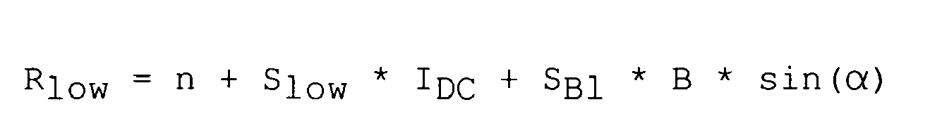
- R low indicates the number of quantization steps at saturation of the control core.
- R high represents the number of unsaturated control core.
- the variable n indicates the zero point of the magnetic-field-sensitive component in quantization steps, in which current 0A is present in the electrical conductor and the flux density is applied to the magnetic-field-sensitive component 0.
- the variables S low and S high indicate the sensitivity of the magnetic-field-sensitive component in the case of a saturated or unsaturated control core.
- the variable B denotes the magnetic The flux density of an external magnetic field and the variable ⁇ indicates the angle from which the external magnetic field impinges on the magnetic field-sensitive component.
- the variable I DC indicates the current flowing through the conductor to be determined in the measurement.
- the additionally soft-magnetic elements additionally arranged in the vicinity of the magnetic-field-sensitive component now make it possible to match the variables S Bl and S Bh .
- the linear equation system for determining the current intensity I DC can be solved in a simple manner.
- I DC R low - R high / S low - S high
- FIG. 1 a possible variant of the exemplary arrangement for measuring a current flowing in an electrical conductor 1 is shown, in which a magnetic circuit 2, which may consist of ferrite, surrounds an electrical conductor.
- the magnetic circuit 2 has on one side an air gap 3, in which a magnetic field-sensitive component 4 is located.
- a control core 5 To control the air gap 3 is located in the air gap 3, a control core 5.
- the control core 5 is arranged centrally in the air gap 3, so that between the U-shaped magnetic circuit 2 and the control core 5 on both sides of the control core 5 each have a gap 8a, 8b is.
- the magnetic field-sensitive device 4 is arranged in the first gap 8a.
- the thickness of the magnetic field-sensitive component 4 and the height of the gap 8a are approximately equal, so that the magnetic field-sensitive component 4 rests both on the magnetic circuit 2 and on the control core 5.
- the control core 5 has control windings 6, which can bring the control core 5 in the magnetic saturation.
- the control core 5 has in the vicinity of the magnetic field-sensitive component 4 additional magnetizable elements 7a, 7b.
- a first additional element 7a is preferably arranged within the control core 5.
- the additional element is preferably rod-shaped.
- Another additional magnetizable element 7b is preferably at the edge of the upper leg of the control core 5 is arranged.
- the outer additional element 7b is thus arranged on the outside of the control core 5, wherein in a preferred embodiment it may be formed as a part of the control core 5.
- another magnetic field-sensitive device 4 can be introduced to increase the measurement accuracy by a double measurement.
- FIG. 2 a section of the exemplary arrangement for measuring a current flowing in an electrical conductor 1 is shown.
- the section shows the area around the magnetic field-sensitive component 4.
- the magnetic field-sensitive component 4 is located in the gap 8a between the control core 5 and the magnetic circuit 2.
- the control core 5 has control windings 6, which serve to saturate the control core 5.
- additional magnetizable elements 7a, 7b which preferably consist of soft magnetic material.
- a first additional element 7a is located within the control core 5 between the control windings 6.
- the additional element 7a is rod-shaped.
- Another additional element 7b is attached to the outside of the control core 5.
- the additional element 7b is preferably formed as part of the control core 5.
- the additional magnetizable elements have a residual permeability even with complete saturation of the control core 5.
Landscapes
- Physics & Mathematics (AREA)
- General Physics & Mathematics (AREA)
- Measuring Instrument Details And Bridges, And Automatic Balancing Devices (AREA)
- Transformers For Measuring Instruments (AREA)
- Measuring Magnetic Variables (AREA)
Description
- Aus der Druckschrift
DE 10 2005 024 075 B4 ist eine Vorrichtung zur Messung eines in einem elektrischen Leiter fließenden Stroms bekannt. - Eine zu lösende Aufgabe besteht darin, eine Anordnung und ein Verfahren zur Messung eines in einem elektrischen Leiter fließenden Stroms anzugeben, welche unabhängig von äußeren magnetischen Einflüssen eine korrekte Messung ermöglicht.
- Diese Aufgabe wird durch eine Anordnung zur Messung eines in einem elektrischen Leiter fließenden Stroms gemäß Anspruch 1 gelöst.
- Die Anordnung weist einen mit einem Luftspalt versehenen Magnetkreis zur Kopplung mit einem elektrischen Leiter auf. Im Luftspalt des Magnetkreises befindet sich ein Steuerkern, der zur Steuerung des Luftspalts vorgesehen ist. Der Steuerkern weist eine Steuerwicklung zu seiner magnetischen Sättigung auf. In dem Luftspalt des Magnetkreises ist ein magnetfeldsensitives Bauelement zur Messung des vom elektrischen Leiter erzeugten Magnetfeldes angeordnet. Das magnetfeldsensitive Bauelement ist einseitig des Steuerkerns angeordnet. In einer Ausführungsform kann ein zweites magnetfeldsensitives Bauelement auf der dem ersten magnetfeldsensitiven Bauelement gegenüberliegenden Seite des Steuerkerns angeordnet sein. In der Nähe des ersten magnetfeldsensitiven Bauelements befinden sich mehrere zusätzliche Elemente. Diese Elemente eignen sich unabhängig von dem Steuerkern zur Führung von Magnetfeldern in der Umgebung des magnetfeldsensitiven Bauelements.
- In einer bevorzugten Ausführungsform ist ein erstes Element innerhalb des Steuerkerns angeordnet, ein zweites außerhalb des Steuerkerns.
- Der Steuerkern ist bevorzugt in dem Luftspalt des Magnetkreises angeordnet, so dass Spalte ober- und unterhalb zwischen dem Steuerkern und dem Magnetkreis entstehen.
- In einer weiteren Ausführungsform ist der Luftspalt asymmetrisch angeordnet, so dass vorzugsweise unterschiedlich große Spalte ober- und unterhalb zwischen dem Steuerkern und dem Magnetkreis entstehen.
- Die in der Nähe des Steuerkerns befindlichen Elemente sind bevorzugt magnetisierbar.
- Bevorzugt weisen die zusätzlichen Elemente eine Permeabilitätszahl auf, die größer als 1 ist.
- Für die zusätzlichen Elemente eignen sich besonders weichmagnetische Materialien, die eine Permeabilitätszahl aufweisen, die größer oder gleich der Permeabilitätszahl des Steuerkerns ist. Dafür geeignet sind vorzugsweise Materialien, die auch für den Steuerkern Verwendung finden.
- Die zusätzlichen Elemente sind bevorzugt in der Nähe eines ersten magnetfeldsensitiven Bauelements angeordnet, sodass mögliche magnetische Störfelder effektiv in der Nähe des magnetfeldsensitiven Bauelements gebündelt und durch das magnetfeldsensitive Bauelement hindurchgeführt werden können. In einer Ausführungsform ist es auch möglich, dass die Elemente als ein integraler Bestandteil eines einteiligen Steuerkerns ausgebildet sind. Hierbei ist eine Auswölbung des Steuerkerns und eine Verdickung des Steuerkerns in der näheren Umgebung des magnetfeldsensitiven Bauelements möglich, sodass zwischen einem der zusätzlichen Elemente und dem magnetfeldsensitiven Bauelement ein möglichst kleiner Luftspalt zustande kommt.
- Die Bereiche der Verdickung oder Auswölbung des Steuerkerns weisen auch bei Sättigung der Steuerkerne noch eine Restpermeabilität auf.
- In einer weiteren Ausführung bestehen die zusätzlichen Elemente aus mehreren Einzelteilen, die jeweils zu einem zusätzlichen Element zusammengefügt werden können.
- Bevorzugt weisen die zusätzlichen Elemente bei vollständiger Sättigung des Steuerkerns durch die Steuerwicklungen eine Restpermeabilität auf, sodass störende Magnetfelder auch bei Sättigung des Steuerkerns weiterhin von den zusätzlichen Elementen gebündelt und durch das magnetfeldsensitive Bauelement geführt werden können.
- In einer bevorzugten Ausführungsform bestehen die zusätzlichen Elemente aus ferromagnetischem Material, beispielsweise einem Ferrit, einer nanokristallinen Metalllegierung oder aus Permalloy. Es eignen sich jedoch auch andere Materialien, die ferromagnetische Eigenschaften aufweisen.
- In einer Ausführungsform weist der Magnetkreis eine zusätzliche Wicklung auf. Durch die zusätzliche Wicklung kann der Magnetkreis durch einen kurzen Stromimpuls magnetisiert werden. Nach dem Stromimpuls weist der Magnetkreis eine definierte Remanenz auf, die zur Einstellung des Nullpunktes herangezogen werden kann.
- Um eine zuverlässige Messung des in dem elektrischen Leiter fließenden Stroms zu ermöglichen, ist der Magnetkreis in der Lage, den elektrischen Leiter in seinem Querschnitt vollständig zu umgreifen.
- In einer bevorzugten Ausführungsform ist der Steuerkern als Ferritkern ausgebildet. Dabei ist der Ferritkern besonders bevorzugt als rechteckiger Rahmen ausgebildet, der auf mindestens einer Seite des Rahmens eine Steuerwicklung zur Sättigung des Ferritkerns aufweist. In einer besonders effizienten Variante sind Steuerwicklungen auf zwei gegenüberliegenden Seiten des Rahmens angeordnet. Durch die Ausbildung des Steuerkerns in dieser Form kann eine effiziente Sättigung des Steuerkerns erreicht werden.
- Dadurch, dass in dem Magnetkreis nur ein Steuerkern angeordnet ist, kann dieser im Vergleich zu einem Aufbau mit zwei Steuerkernen mehr als die doppelte Anzahl Windungen auf den Steuerkern aufweisen, sodass bei gleichem Drahtdurchmesser der Steuerwicklungen die doppelte Anzahl an Amperewindungen verfügbar sind. Dies ermöglicht die Messung sehr großer Ströme, ohne dass die Steuerkerne vom Primärstrom aus der Sättigung getrieben werden. Bei sehr großen Strömen, die im Bereich von ca. 1000 liegen, würde der Primärstrom dem Steuerstrom in einem der Schenkel des Steuerkerns entgegenwirken und ihn so aus der Sättigung treiben.
- Das magnetfeldsensitive Bauelement ist bevorzugt ein Hall-Sensor.
- Wird ein Hall-Sensor von einem Strom durchflossen und ist in einem senkrecht dazu verlaufendes Magnetfeld gebracht, liefert er eine Ausgangsspannung, die proportional zum Produkt aus magnetischer Feldstärke und Strom ist.
- Zur Bestimmung des in dem elektrischen Leiter fließenden Stroms werden verschiedene Messungen mit Hilfe des Hall-Sensors durchgeführt.
- Die oben genannte Aufgabe wird ebenfalls durch eine Verfahren zur Messung eines in einem elektrischen Leiter fließenden Stroms gemäß Anspruch 13 gelöst.
- Magnetfelder in der Umgebung des magnetfeldsensitiven Bauelements, die nicht durch den elektrischen Leiter oder die Steuerwicklung hervorgerufen werden, können die Messungen in erheblichem Ausmaß verschlechtern.
- Eine erste Messung wird bei gesättigtem Steuerkern, eine weitere bei ungesättigtem Steuerkern durchgeführt. Durch die außen angebrachten zusätzlichen magnetisierbaren Elemente werden externe magnetische Störfelder derart beeinflusst, dass sich Beiträge externer magnetischer Störfelder in den Gleichungen zur Berechnung der Stromstärke gleichen und somit eliminiert werden können.
- Das erste zusätzliche Element im Inneren des Steuerkerns wird benötigt, um die Empfindlichkeit für externe Magnetfelder im Fall der Sättigung des Steuerkerns zu erhöhen, sodass sich die Beiträge externer magnetischer Störfelder in den Gleichungen zur Berechnung des Stromstärke gleichen. Vorzugsweise befindet sich zwischen dem Steuerkern und dem Magnetkreis jeweils ober- und unterhalb ein Luftspalt. Der zusätzliche Luftspalt unterhalb des Steuerkerns unterstützt die Wirkung des außen angebrachten zusätzlichen Elementes aus magnetisierbarem Material. In dem Luftspalt unterhalb des Steuerkerns kann ein weiteres magnetfeldsensitives Bauelement zwischen dem Steuerkern und dem Magnetkreis angeordnet sein. Durch paralleles Auslesen und Mittelung der Messwerte oder der Messergebnisse kann die Messgenauigkeit erhöht werden.
- Aus den zwei Messungen bei gesättigtem und ungesättigtem Steuerkern kann unter Berücksichtigung von bestimmten Faktoren, die sich durch die Sensitivität des Hall-Sensors bei gesättigtem beziehungsweise ungesättigtem Steuerkern ergeben, über bekannte Gleichungen die Stromstärke des durch den elektrischen Leiter fließenden Stroms berechnet werden.
- Durch die neu hinzugefügten Elemente aus bevorzugt weichmagnetischem Material können störende Einflüsse durch externe Magnetfelder in den Gleichungen sowohl bei gesättigtem Steuerkern als auch bei ungesättigtem Steuerkern eliminiert werden, da diese Beiträge durch die zusätzlichen Elemente aneinander angeglichen werden können. Dadurch kann das lineare Gleichungssystem auf einfache Art und Weise gelöst werden und die Stromstärke des elektrischen Leiters ermittelt werden.
- Durch die sowohl innerhalb des Steuerkerns als auch außerhalb des Steuerkerns angebrachten zusätzlichen Elemente werden die Eintrittswinkel für externe magnetische Störfelder bei gesättigtem und ungesättigtem Steuerkern angeglichen. In diesem Fall heben sich die Beiträge der externen Störmagnetfelder auf, die Stromstärke kann durch einfache Subtraktion der beiden Gleichungen ermittelt werden.
- In der Messung werden physikalische Größen oft in analoge elektrische Größen umgewandelt. Bei der Quantisierung wird der Messbereich der analogen Größe in eine endliche Zahl aneinander angrenzender Teilbereiche (Intervalle) aufgeteilt und jedem davon ein Wert eines endlichen symbolischen Systems zugeordnet (z.B. eine ganze Zahl). Als Auflösung wird die Anzahl der verwendeten Teilbereiche der analogen Größe, bei binären symbolischen Systemen auch ihre Zweierpotenz (Auflösung in Bit) bezeichnet, jedoch bei gleich großen Intervallen auch die Größe der Intervalle selbst.
- Die Quantisierungsschritte geben den Wert für das Messsignal in diskreter Form wieder.
- Dabei werden folgende zwei Gleichungen aufgestellt:
- I.
- II.
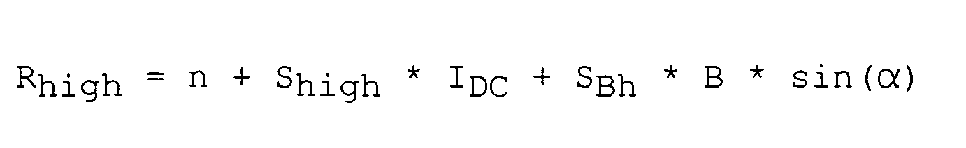
- In den oben angeführten Gleichungen gibt Rlow die Anzahl der Quantisierungsschritte bei Sättigung des Steuerkerns an. Rhigh gibt die Anzahl bei ungesättigtem Steuerkern wieder. Die Variable n gibt den Nullpunkt des magnetfeldsensitiven Bauelements in Quantisierungsschritten an, bei dem im elektrischen Leiter 0A Strom und am magnetfeldsensitiven Bauelement 0 Tesla Flussdichte anliegen. Die Variablen Slow und Shigh geben die Sensitivität des magnetfeldsensitiven Bauelements bei gesättigtem beziehungsweise bei ungesättigtem Steuerkern an. Die Variable B bezeichnet die magnetische Flussdichte eines externen Magnetfeldes und die Variable α gibt den Winkel an, aus dem das externe Magnetfeld auf das magnetfeldsensitive Bauelement trifft. Die Variable IDC gibt die Stromstärke des Strom durchflossenen Leiters an, die in der Messung ermittelt werden soll.
- Die zusätzlich in der Nähe des magnetfeldsensitiven Bauelements angeordneten bevorzugt weichmagnetischen Elemente ermöglichen es nun, die Variablen SBl und SBh anzugleichen. Dadurch lässt sich das lineare Gleichungssystem zur Bestimmung der Stromstärke IDC auf einfache Art und Weise lösen.
- Da SBl und SBh identisch sind und die Eintrittswinkel der externen Störmagnetfelder bei gesättigtem und ungesättigtem Steuerkern durch den oben beschriebenen Aufbau identisch sind, kann durch Subtraktion der Gleichung (I.) von der Gleichung (II.), oder umgekehrt, IDC ermittelt werden.

- Die Anordnung wird im Folgenden anhand von Ausführungsbeispielen und den dazugehörigen Figuren näher erläutert.
- Die nachfolgend beschriebenen Zeichnungen sind nicht als maßstabsgetreu aufzufassen. Vielmehr können zur besseren Darstellung einzelne Dimensionen vergrößert, verkleinert oder auch verzerrt dargestellt sein.
- Elemente, die einander gleichen oder die die gleiche Funktion übernehmen, sind mit gleichen Bezugszeichen bezeichnet.
- Figur 1
- zeigt eine beispielhafte Anordnung zur Messung eines in einem elektrischen Leiter fließenden Stroms.
- Figur 2
- zeigt einen Ausschnitt einer beispielhaften Anordnung zur Messung eines in einem elektrischen Leiter fließenden Stroms.
- In
Figur 1 ist eine mögliche Variante der beispielhaften Anordnung zur Messung eines in einem elektrischen Leiter 1 fließenden Stroms gezeigt, bei der ein Magnetkreis 2, der aus Ferrit bestehen kann, einen elektrischen Leiter umgreift. Der Magnetkreis 2 weist auf einer Seite einen Luftspalt 3 auf, in dem sich ein magnetfeldsensitives Bauelement 4 befindet. Zur Steuerung des Luftspalts 3 befindet sich in dem Luftspalt 3 ein Steuerkern 5. Der Steuerkern 5 ist mittig in dem Luftspalt 3 angeordnet, so dass zwischen dem U-förmigen Magnetkreis 2 und dem Steuerkern 5 beidseitig des Steuerkerns 5 jeweils ein Spalt 8a, 8b vorhanden ist. In dem ersten Spalt 8a ist das magnetfeldsensitive Bauelement 4 angeordnet. Die Dicke des magnetfeldsensitiven Bauelements 4 und die Höhe des Spalts 8a sind annähernd gleich groß, so dass das magnetfeldsensitive Bauelement 4 sowohl an dem Magnetkreis 2 als auch an dem Steuerkern 5 anliegt. Der Steuerkern 5 weist Steuerwicklungen 6 auf, die den Steuerkern 5 in die magnetische Sättigung bringen können. Der Steuerkern 5 weist in der Nähe des magnetfeldsensitiven Bauelements 4 zusätzliche magnetisierbare Elemente 7a, 7b auf. Ein erstes zusätzliches Element 7a ist bevorzugt innerhalb des Steuerkerns 5 angeordnet. Das zusätzliche Element ist bevorzugt stabförmig ausgebildet. Ein weiteres zusätzliches magnetisierbares Element 7b ist vorzugsweise am Rand des oberen Schenkels des Steuerkerns 5 angeordnet. Das äußere zusätzliche Element 7b ist somit außen am Steuerkern 5 angeordnet, wobei es in einer bevorzugten Ausführungsform als ein Teil des Steuerkerns 5 gebildet sein kann. In den unteren Spalt 8b kann ein weiteres magnetfeldsensitives Bauelement 4 eingebracht werden, um durch eine doppelte Messung die Messgenauigkeit zu erhöhen. - In
Figur 2 ist ein Ausschnitt der beispielhaften Anordnung zur Messung eines in einem elektrischen Leiter 1 fließenden Stroms gezeigt. Der Ausschnitt zeigt den Bereich um das magnetfeldsensitive Bauelement 4. Das magnetfeldsensitive Bauelement 4 befindet sich in dem Spalt 8a zwischen dem Steuerkern 5 und dem Magnetkreis 2. Der Steuerkern 5 weist Steuerwicklungen 6 auf, die zur Sättigung des Steuerkerns 5 dienen. In der Nähe des magnetfeldsensitive Bauelement 4 befinden sich zusätzliche magnetisierbare Elemente 7a, 7b, die bevorzugt aus weichmagnetischem Material bestehen. Ein erstes zusätzliches Element 7a befindet sich innerhalb des Steuerkerns 5 zwischen den Steuerwicklungen 6. In einer bevorzugten Ausführungsform ist das zusätzliche Element 7a stabförmig ausgebildet. Ein weiteres zusätzliches Element 7b ist außen am Steuerkern 5 angebracht. Das zusätzliche Element 7b ist bevorzugt als Teil des Steuerkerns 5 ausgebildet. Die zusätzlichen magnetisierbaren Elemente weisen auch bei vollständiger Sättigung des Steuerkerns 5 eine Restpermeabilität auf. Durch die beiden zusätzlichen magnetisierbaren Elemente 7a, 7b können die Beiträge der störenden äußeren Magnetfelder in den Gleichungen des durch den elektrischen Leiter fließenden Stroms angeglichen werden, so dass die Beiträge in den Gleichungen herausgekürzt werden können. - Obwohl in den Ausführungsbeispielen nur eine beschränkte Anzahl möglicher Weiterbildungen der Erfindung beschrieben werden konnte, ist die Erfindung nicht auf diese beschränkt. Es ist prinzipiell möglich, eine andere Anzahl der Steuerwicklungen oder eine andere Form des Magnetkreises für die Anordnung zu verwenden. Die Erfindung ist nicht auf die Anzahl der schematisch dargestellten Elemente beschränkt.
- Die Beschreibung der hier angegebenen Gegenstände und Verfahren ist nicht auf die einzelnen speziellen Ausführungsformen beschränkt. Vielmehr können die Merkmale der einzelnen Ausführungsformen - soweit technisch sinnvoll - beliebig miteinander kombiniert werden.
-
- 1
- elektrischer Leiter
- 2
- Magnetkreis
- 3
- Luftspalt
- 4
- magnetfeldsensitives Bauelement
- 5
- Steuerkern
- 6
- Steuerwicklung
- 7a, 7b
- zusätzliche Elemente
- 8a, 8b
- Spalt
Claims (15)
- Anordnung zur Messung eines in einem elektrischen Leiter (1) fließenden Stroms, aufweisend- einen Magnetkreis (2) mit Luftspalt (3) zur Kopplung mit dem elektrischen Leiter (1),- ein oder mehrere im Luftspalt (3) des Magnetkreises (2) angeordnete magnetfeldsensitive Bauelemente (4) zur Messung des vom elektrischen Leiter (1) erzeugten Magnetfelds,- einen Steuerkern (5) zur Steuerung des Luftspalts (3) , der in dem Luftspalt (3) angeordnet ist,- wobei der Steuerkern (5) eine Steuerwicklung (6) zur magnetischen Sättigung des Steuerkerns (5) aufweist,wobei ein magnetfeldsensitives Bauelement (4) auf einer ersten Seite des Steuerkerns (5) angeordnet ist und sich in der Nähe des magnetfeldsensitiven Bauelements (4) mehrere zusätzliche Elemente (7a, 7b) befinden, die unabhängig von dem Steuerkern (5) zur Führung von Magnetfeldern in der Umgebung des magnetfeldsensitiven Bauelements (4) geeignet sind, wobei ein erstes zusätzliches Element (7a) innerhalb des Steuerkerns (5) und ein zweites zusätzliches Element (7b) außerhalb des Steuerkerns (5) angeordnet ist.
- Anordnung nach Anspruch 1, bei der die zusätzlichen Elemente (7a, 7b) magnetisierbar sind.
- Anordnung nach einem der vorhergehenden Ansprüche, bei der die zusätzlichen Elemente (7a, 7b) eine Permeabilitätszahl von vorzugsweise > 1 aufweisen.
- Anordnung nach einem der vorhergehenden Ansprüche, bei der die zusätzlichen Elemente (7a, 7b) aus einem weichmagnetischen Material bestehen.
- Anordnung nach einem der vorhergehenden Ansprüche, bei der die zusätzlichen Elemente (7a, 7b) eine Permeabilitätszahl aufweisen, die größer oder gleich der Permeabilitätszahl des Steuerkerns (5) ist.
- Anordnung nach einem der vorhergehenden Ansprüche, bei der die zusätzlichen Elemente (7a, 7b) eine beliebige Form aufweisen oder jeweils aus mehreren Einzelelementen bestehen.
- Anordnung nach einem der vorhergehenden Ansprüche, bei dem die zusätzlichen Elemente (7a, 7b) einen Teil des Steuerkerns (5) darstellen.
- Anordnung nach einem der vorhergehenden Ansprüche, bei der die zusätzlichen Elemente (7a, 7b) eine Restpermeabilität aufweisen, wenn der Steuerkern (5) gesättigt ist.
- Anordnung nach einem der vorhergehenden Ansprüche, bei der der Magnetkreis (2) eine zusätzliche wicklung aufweist.
- Anordnung nach einem der vorhergehenden Ansprüche, bei der der Steuerkern (5) als Ferritkern ausgebildet ist.
- Anordnung nach einem der vorhergehenden Ansprüche, bei der der Magnetkreis (2) und Steuerkern (5) voneinander beabstandet sind, so dass die Anordnung zwischen dem Magnetkreis (2) und dem Steuerkern (5) beidseitig jeweils einen Spalt (8a, 8b) aufweist.
- Anordnung nach einem der vorhergehenden Ansprüche, bei der das magnetfeldsensitive Bauelement (4) ein Hall-Sensor ist.
- Verfahren zur Messung eines in einem elektrischen Leiter (1) fließenden Stroms mit den Schritten:- Koppeln eines Magnetkreises (2) mit dem elektrischen Leiter (1), wobei der Magnetkreis (2) einen Luftspalt (3) und einen in dem Luftspalt (3) angeordneten Steuerkern (5) zur Steuerung des Luftspalts (3) aufweist,- Messung eines ersten Magnetfelds bei gesättigtem Steuerkern (5) durch ein oder mehrere im Luftspalt (3) angeordnete magnetfeldsensitive Bauelemente (4);- Messung eines zweiten Magnetfelds bei ungesättigtem Steuerkern (5) durch das oder die magnetfeldsensitiven Bauelemente (4);- Eliminieren von störenden Einflüssen externer Magnetfelder durch Beeinflussen der störenden externen Magnetfelder durch ein erstes, innerhalb des Steuerkerns (5) angeordnetes zusätzliches Element (7a) und ein zweites, außerhalb des Steuerkerns (5) angeordnetes zusätzliches Element (7b), die unabhängig von dem Steuerkern (5) zur Führung von Magnetfeldern in der Umgebung eines magnetfeldsensitiven Bauelements (4) geeignet sind, so dass sich Beiträge zur Berechnung einer Stromstärke bei der ersten Messung und bei der zweiten Messung gleichen.
- Verfahren nach Anspruch 13, wobei der Schritt des Eliminierens von störenden Einflüssen umfasst:- Erhöhen einer Empfindlichkeit zur Messung des externen Magnetfeldes bei gesättigtem Steuerkern (2) durch das erste, im Inneren des Steuerkerns (5) angeordnete zusätzliche Element (7a).
- Verfahren nach Anspruch 13 oder 14, wobei der Schritt des Eliminierens von störenden Einflüssen umfasst:- Angleichen der Eintrittswinkel der externen Magnetfelder bei gesättigtem und bei ungesättigtem Steuerkern (2) durch sowohl das erste, im Inneren des Steuerkerns (5) angeordnetes zusätzliches Element (7a) als auch das zweite, außerhalb des Steuerkerns angeordnete zusätzliche Element (7b).
Applications Claiming Priority (2)
| Application Number | Priority Date | Filing Date | Title |
|---|---|---|---|
| DE102007036674A DE102007036674A1 (de) | 2007-08-03 | 2007-08-03 | Anordnung zur Messung eines in einem elektrischen Leiter fließenden Stroms |
| PCT/EP2008/060100 WO2009019200A1 (de) | 2007-08-03 | 2008-07-31 | Anordnung zur messung eines in einem elektrischen leiter fliessenden stroms |
Publications (2)
| Publication Number | Publication Date |
|---|---|
| EP2174147A1 EP2174147A1 (de) | 2010-04-14 |
| EP2174147B1 true EP2174147B1 (de) | 2012-03-07 |
Family
ID=40011395
Family Applications (1)
| Application Number | Title | Priority Date | Filing Date |
|---|---|---|---|
| EP08786721A Not-in-force EP2174147B1 (de) | 2007-08-03 | 2008-07-31 | Anordnung zur messung eines in einem elektrischen leiter fliessenden stroms |
Country Status (7)
| Country | Link |
|---|---|
| US (1) | US7911198B2 (de) |
| EP (1) | EP2174147B1 (de) |
| JP (1) | JP2010536011A (de) |
| CN (1) | CN101772707B (de) |
| AT (1) | ATE548662T1 (de) |
| DE (1) | DE102007036674A1 (de) |
| WO (1) | WO2009019200A1 (de) |
Families Citing this family (7)
| Publication number | Priority date | Publication date | Assignee | Title |
|---|---|---|---|---|
| DE102007036573A1 (de) * | 2007-08-03 | 2009-02-19 | Epcos Ag | Anordnung und Verfahren zur Messung eines in einem elektrischen Leiter fließenden Stroms |
| US10363453B2 (en) | 2011-02-07 | 2019-07-30 | New Balance Athletics, Inc. | Systems and methods for monitoring athletic and physiological performance |
| EP2515125B1 (de) * | 2011-04-21 | 2017-02-01 | Abb Ag | Stromsensor mit Magnetkern |
| EP2853904A1 (de) * | 2013-09-30 | 2015-04-01 | LEM Intellectual Property SA | Aufklemmbarer Stromwandler oder Stromtransformator |
| EP3309559A1 (de) * | 2016-10-11 | 2018-04-18 | LEM Intellectual Property SA | Stromwandler |
| EP4094085A1 (de) * | 2020-01-21 | 2022-11-30 | Abb Schweiz Ag | Verfahren und system für einen verbesserten stromsensor |
| CN115854849B (zh) * | 2023-02-03 | 2023-09-22 | 江阴天润信息技术有限公司 | 一种电磁非接触式钢丝在线计米测速方法及其装置 |
Family Cites Families (11)
| Publication number | Priority date | Publication date | Assignee | Title |
|---|---|---|---|---|
| US4059798A (en) * | 1976-03-08 | 1977-11-22 | F. W. Bell, Inc. | Method and apparatus for measuring the current flowing in a workpiece |
| DE3040316C2 (de) * | 1980-10-25 | 1983-11-10 | Grundig E.M.V. Elektro-Mechanische Versuchsanstalt Max Grundig & Co KG, 8510 Fürth | Verfahren und Vorrichtung zur kontaktlosen Messung von Gleich- und Wechselströmen, insbesondere von Strom-Augenblickswerten |
| DE4113496A1 (de) * | 1991-04-25 | 1992-10-29 | Vacuumschmelze Gmbh | Magnetkern fuer einen stromsensor nach dem kompensationsprinzip |
| JP3007553B2 (ja) * | 1995-03-24 | 2000-02-07 | 日本レム株式会社 | 電流センサ |
| DE69920890T2 (de) * | 1999-01-21 | 2005-02-03 | Tdk Corp. | Stromsensor |
| EP1617228B1 (de) * | 2004-07-16 | 2008-10-22 | Liaisons Electroniques-Mecaniques Lem S.A. | Stromsensor |
| DE102006016745B4 (de) | 2005-04-08 | 2014-07-03 | Epcos Ag | Stromsensor mit hoher Dynamik und Verfahren zu seinem Betrieb |
| DE102005024075B4 (de) | 2005-05-25 | 2007-04-12 | Lisa Dräxlmaier GmbH | Verfahren und Vorrichtung zur Messung eines in einem elektrischen Leiter fließenden Stroms |
| DE102005040316B4 (de) * | 2005-08-25 | 2007-09-27 | Lisa Dräxlmaier GmbH | Vorrichtung und Verfahren zur Messung eines in einem elektrischen Leiter fließenden Stromes |
| DE102006032762B8 (de) * | 2006-07-14 | 2009-10-08 | Lisa Dräxlmaier GmbH | Verfahren zur Messung eines in einem elektrischen Leiter fließenden Stromes und Verwendung des Verfahrens sowie einer Vorrichtung zur Überwachung von Strömen im Bordnetz eines Kraftfahrzeugs |
| DE102007025505A1 (de) | 2007-06-01 | 2008-12-04 | Epcos Ag | Anordnung zur Messung eines in einem elektrischen Leiter fließenden Stroms |
-
2007
- 2007-08-03 DE DE102007036674A patent/DE102007036674A1/de not_active Ceased
-
2008
- 2008-07-31 AT AT08786721T patent/ATE548662T1/de active
- 2008-07-31 CN CN2008801017981A patent/CN101772707B/zh not_active Expired - Fee Related
- 2008-07-31 EP EP08786721A patent/EP2174147B1/de not_active Not-in-force
- 2008-07-31 WO PCT/EP2008/060100 patent/WO2009019200A1/de not_active Ceased
- 2008-07-31 JP JP2010518684A patent/JP2010536011A/ja not_active Withdrawn
-
2010
- 2010-02-02 US US12/698,718 patent/US7911198B2/en not_active Expired - Fee Related
Also Published As
| Publication number | Publication date |
|---|---|
| JP2010536011A (ja) | 2010-11-25 |
| US7911198B2 (en) | 2011-03-22 |
| CN101772707A (zh) | 2010-07-07 |
| CN101772707B (zh) | 2012-07-04 |
| EP2174147A1 (de) | 2010-04-14 |
| WO2009019200A1 (de) | 2009-02-12 |
| ATE548662T1 (de) | 2012-03-15 |
| WO2009019200A8 (de) | 2010-03-04 |
| DE102007036674A1 (de) | 2009-02-05 |
| US20100181991A1 (en) | 2010-07-22 |
Similar Documents
| Publication | Publication Date | Title |
|---|---|---|
| EP2153237B1 (de) | Anordnung zur messung eines in einem elektrischen leiter fliessenden stroms | |
| DE102007046054B4 (de) | Verbesserter hochgenauer Rogowski-Stromwandler | |
| EP2174147B1 (de) | Anordnung zur messung eines in einem elektrischen leiter fliessenden stroms | |
| EP3259603B1 (de) | Strommessvorrichtung und verfahren zur bestimmung eines elektrischen stroms | |
| DE102009034233B4 (de) | Magneterfassungssystem, Verfahren zum Erzeugen eines Magnetsensors und Magneterfassungsverfahren | |
| EP2666023B1 (de) | Strommessvorrichtung | |
| DE102008039568A1 (de) | Stromerfassungsvorrichtung | |
| DE102010039820A1 (de) | Leistungsschalter mit Rogowski-Stromwandlern zum Messen des Stroms in den Leitern des Leistungsschalters | |
| DE19542899B4 (de) | Wechselstromsensor auf der Basis einer Parallelplattengeometrie und mit einem Shunt zur Selbstspeisung | |
| DE60029573T2 (de) | Verbesserte stromfühleranordnung für niederspannungs-leistungsschalter | |
| EP3341746B1 (de) | Verfahren und anordnung zur bestimmung der querempfindlichkeit von magnetfeldsensoren | |
| DE60026952T2 (de) | Stromsensor | |
| EP1726967B1 (de) | Verfahren und Vorrichtung zur Messung eines in einem elektrischen Leiter fliessenden Stroms | |
| EP2174146B1 (de) | Anordnung und verfahren zur messung eines in einem elektrischen leiter fliessenden stroms | |
| EP2998749A1 (de) | Strommessvorrichtung und verfahren zum erfassen eines stroms | |
| CH696859A5 (de) | Stromsensor mit mehreren Magnetfeldsensoren. | |
| EP3069150A1 (de) | Vorrichtung, anordnung und verfahren zur messung einer stromstärke in einem stromdurchflossenen primärleiter | |
| EP4133287B1 (de) | Umfangsgleichverteilte magnetfeldsensoranordnung zur messung eines magnetischen feldes eines leiters eines elektrischen stroms | |
| DE202013010178U1 (de) | Stromerfassungsvorrichtung | |
| EP2992337B1 (de) | Verfahren und vorrichtung zur überwachung und strommessung an einer magnetisch vorgespannten drossel | |
| EP3992599B1 (de) | Magnetoelastischer drehmomentsensor | |
| EP2116855B1 (de) | Strommesseinrichtung | |
| DE102012216554B4 (de) | Gleichstrommessung | |
| DE102023108272A1 (de) | Verfahren und Mess-Anordnung zur Messung der Stromstärke eines durch einen Leiter fließenden elektrischen Stroms | |
| EP2315044B1 (de) | Differenzmagnetometersonde |
Legal Events
| Date | Code | Title | Description |
|---|---|---|---|
| PUAI | Public reference made under article 153(3) epc to a published international application that has entered the european phase |
Free format text: ORIGINAL CODE: 0009012 |
|
| 17P | Request for examination filed |
Effective date: 20100225 |
|
| AK | Designated contracting states |
Kind code of ref document: A1 Designated state(s): AT BE BG CH CY CZ DE DK EE ES FI FR GB GR HR HU IE IS IT LI LT LU LV MC MT NL NO PL PT RO SE SI SK TR |
|
| AX | Request for extension of the european patent |
Extension state: AL BA MK RS |
|
| DAX | Request for extension of the european patent (deleted) | ||
| 17Q | First examination report despatched |
Effective date: 20101022 |
|
| GRAP | Despatch of communication of intention to grant a patent |
Free format text: ORIGINAL CODE: EPIDOSNIGR1 |
|
| GRAS | Grant fee paid |
Free format text: ORIGINAL CODE: EPIDOSNIGR3 |
|
| GRAA | (expected) grant |
Free format text: ORIGINAL CODE: 0009210 |
|
| AK | Designated contracting states |
Kind code of ref document: B1 Designated state(s): AT BE BG CH CY CZ DE DK EE ES FI FR GB GR HR HU IE IS IT LI LT LU LV MC MT NL NO PL PT RO SE SI SK TR |
|
| REG | Reference to a national code |
Ref country code: GB Ref legal event code: FG4D Free format text: NOT ENGLISH |
|
| REG | Reference to a national code |
Ref country code: AT Ref legal event code: REF Ref document number: 548662 Country of ref document: AT Kind code of ref document: T Effective date: 20120315 Ref country code: CH Ref legal event code: EP |
|
| REG | Reference to a national code |
Ref country code: IE Ref legal event code: FG4D Free format text: LANGUAGE OF EP DOCUMENT: GERMAN |
|
| REG | Reference to a national code |
Ref country code: DE Ref legal event code: R096 Ref document number: 502008006628 Country of ref document: DE Effective date: 20120503 |
|
| REG | Reference to a national code |
Ref country code: NL Ref legal event code: VDEP Effective date: 20120307 |
|
| PG25 | Lapsed in a contracting state [announced via postgrant information from national office to epo] |
Ref country code: NO Free format text: LAPSE BECAUSE OF FAILURE TO SUBMIT A TRANSLATION OF THE DESCRIPTION OR TO PAY THE FEE WITHIN THE PRESCRIBED TIME-LIMIT Effective date: 20120607 Ref country code: LT Free format text: LAPSE BECAUSE OF FAILURE TO SUBMIT A TRANSLATION OF THE DESCRIPTION OR TO PAY THE FEE WITHIN THE PRESCRIBED TIME-LIMIT Effective date: 20120307 Ref country code: HR Free format text: LAPSE BECAUSE OF FAILURE TO SUBMIT A TRANSLATION OF THE DESCRIPTION OR TO PAY THE FEE WITHIN THE PRESCRIBED TIME-LIMIT Effective date: 20120307 Ref country code: NL Free format text: LAPSE BECAUSE OF FAILURE TO SUBMIT A TRANSLATION OF THE DESCRIPTION OR TO PAY THE FEE WITHIN THE PRESCRIBED TIME-LIMIT Effective date: 20120307 |
|
| LTIE | Lt: invalidation of european patent or patent extension |
Effective date: 20120307 |
|
| PG25 | Lapsed in a contracting state [announced via postgrant information from national office to epo] |
Ref country code: LV Free format text: LAPSE BECAUSE OF FAILURE TO SUBMIT A TRANSLATION OF THE DESCRIPTION OR TO PAY THE FEE WITHIN THE PRESCRIBED TIME-LIMIT Effective date: 20120307 Ref country code: GR Free format text: LAPSE BECAUSE OF FAILURE TO SUBMIT A TRANSLATION OF THE DESCRIPTION OR TO PAY THE FEE WITHIN THE PRESCRIBED TIME-LIMIT Effective date: 20120608 Ref country code: FI Free format text: LAPSE BECAUSE OF FAILURE TO SUBMIT A TRANSLATION OF THE DESCRIPTION OR TO PAY THE FEE WITHIN THE PRESCRIBED TIME-LIMIT Effective date: 20120307 |
|
| PG25 | Lapsed in a contracting state [announced via postgrant information from national office to epo] |
Ref country code: CY Free format text: LAPSE BECAUSE OF FAILURE TO SUBMIT A TRANSLATION OF THE DESCRIPTION OR TO PAY THE FEE WITHIN THE PRESCRIBED TIME-LIMIT Effective date: 20120307 |
|
| PG25 | Lapsed in a contracting state [announced via postgrant information from national office to epo] |
Ref country code: SE Free format text: LAPSE BECAUSE OF FAILURE TO SUBMIT A TRANSLATION OF THE DESCRIPTION OR TO PAY THE FEE WITHIN THE PRESCRIBED TIME-LIMIT Effective date: 20120307 Ref country code: IS Free format text: LAPSE BECAUSE OF FAILURE TO SUBMIT A TRANSLATION OF THE DESCRIPTION OR TO PAY THE FEE WITHIN THE PRESCRIBED TIME-LIMIT Effective date: 20120707 Ref country code: EE Free format text: LAPSE BECAUSE OF FAILURE TO SUBMIT A TRANSLATION OF THE DESCRIPTION OR TO PAY THE FEE WITHIN THE PRESCRIBED TIME-LIMIT Effective date: 20120307 Ref country code: PL Free format text: LAPSE BECAUSE OF FAILURE TO SUBMIT A TRANSLATION OF THE DESCRIPTION OR TO PAY THE FEE WITHIN THE PRESCRIBED TIME-LIMIT Effective date: 20120307 Ref country code: SI Free format text: LAPSE BECAUSE OF FAILURE TO SUBMIT A TRANSLATION OF THE DESCRIPTION OR TO PAY THE FEE WITHIN THE PRESCRIBED TIME-LIMIT Effective date: 20120307 Ref country code: RO Free format text: LAPSE BECAUSE OF FAILURE TO SUBMIT A TRANSLATION OF THE DESCRIPTION OR TO PAY THE FEE WITHIN THE PRESCRIBED TIME-LIMIT Effective date: 20120307 Ref country code: CZ Free format text: LAPSE BECAUSE OF FAILURE TO SUBMIT A TRANSLATION OF THE DESCRIPTION OR TO PAY THE FEE WITHIN THE PRESCRIBED TIME-LIMIT Effective date: 20120307 |
|
| PG25 | Lapsed in a contracting state [announced via postgrant information from national office to epo] |
Ref country code: SK Free format text: LAPSE BECAUSE OF FAILURE TO SUBMIT A TRANSLATION OF THE DESCRIPTION OR TO PAY THE FEE WITHIN THE PRESCRIBED TIME-LIMIT Effective date: 20120307 Ref country code: PT Free format text: LAPSE BECAUSE OF FAILURE TO SUBMIT A TRANSLATION OF THE DESCRIPTION OR TO PAY THE FEE WITHIN THE PRESCRIBED TIME-LIMIT Effective date: 20120709 |
|
| PLBE | No opposition filed within time limit |
Free format text: ORIGINAL CODE: 0009261 |
|
| STAA | Information on the status of an ep patent application or granted ep patent |
Free format text: STATUS: NO OPPOSITION FILED WITHIN TIME LIMIT |
|
| BERE | Be: lapsed |
Owner name: EPCOS A.G. Effective date: 20120731 |
|
| PG25 | Lapsed in a contracting state [announced via postgrant information from national office to epo] |
Ref country code: DK Free format text: LAPSE BECAUSE OF FAILURE TO SUBMIT A TRANSLATION OF THE DESCRIPTION OR TO PAY THE FEE WITHIN THE PRESCRIBED TIME-LIMIT Effective date: 20120307 |
|
| 26N | No opposition filed |
Effective date: 20121210 |
|
| PG25 | Lapsed in a contracting state [announced via postgrant information from national office to epo] |
Ref country code: MC Free format text: LAPSE BECAUSE OF NON-PAYMENT OF DUE FEES Effective date: 20120731 |
|
| REG | Reference to a national code |
Ref country code: CH Ref legal event code: PL |
|
| GBPC | Gb: european patent ceased through non-payment of renewal fee |
Effective date: 20120731 |
|
| REG | Reference to a national code |
Ref country code: DE Ref legal event code: R097 Ref document number: 502008006628 Country of ref document: DE Effective date: 20121210 |
|
| PG25 | Lapsed in a contracting state [announced via postgrant information from national office to epo] |
Ref country code: CH Free format text: LAPSE BECAUSE OF NON-PAYMENT OF DUE FEES Effective date: 20120731 Ref country code: ES Free format text: LAPSE BECAUSE OF FAILURE TO SUBMIT A TRANSLATION OF THE DESCRIPTION OR TO PAY THE FEE WITHIN THE PRESCRIBED TIME-LIMIT Effective date: 20120618 Ref country code: LI Free format text: LAPSE BECAUSE OF NON-PAYMENT OF DUE FEES Effective date: 20120731 Ref country code: GB Free format text: LAPSE BECAUSE OF NON-PAYMENT OF DUE FEES Effective date: 20120731 |
|
| REG | Reference to a national code |
Ref country code: IE Ref legal event code: MM4A |
|
| PG25 | Lapsed in a contracting state [announced via postgrant information from national office to epo] |
Ref country code: BE Free format text: LAPSE BECAUSE OF NON-PAYMENT OF DUE FEES Effective date: 20120731 |
|
| PG25 | Lapsed in a contracting state [announced via postgrant information from national office to epo] |
Ref country code: MT Free format text: LAPSE BECAUSE OF FAILURE TO SUBMIT A TRANSLATION OF THE DESCRIPTION OR TO PAY THE FEE WITHIN THE PRESCRIBED TIME-LIMIT Effective date: 20120307 Ref country code: BG Free format text: LAPSE BECAUSE OF FAILURE TO SUBMIT A TRANSLATION OF THE DESCRIPTION OR TO PAY THE FEE WITHIN THE PRESCRIBED TIME-LIMIT Effective date: 20120607 Ref country code: IE Free format text: LAPSE BECAUSE OF NON-PAYMENT OF DUE FEES Effective date: 20120731 |
|
| PG25 | Lapsed in a contracting state [announced via postgrant information from national office to epo] |
Ref country code: TR Free format text: LAPSE BECAUSE OF FAILURE TO SUBMIT A TRANSLATION OF THE DESCRIPTION OR TO PAY THE FEE WITHIN THE PRESCRIBED TIME-LIMIT Effective date: 20120307 |
|
| PG25 | Lapsed in a contracting state [announced via postgrant information from national office to epo] |
Ref country code: LU Free format text: LAPSE BECAUSE OF NON-PAYMENT OF DUE FEES Effective date: 20120731 |
|
| PG25 | Lapsed in a contracting state [announced via postgrant information from national office to epo] |
Ref country code: HU Free format text: LAPSE BECAUSE OF FAILURE TO SUBMIT A TRANSLATION OF THE DESCRIPTION OR TO PAY THE FEE WITHIN THE PRESCRIBED TIME-LIMIT Effective date: 20080731 |
|
| REG | Reference to a national code |
Ref country code: AT Ref legal event code: MM01 Ref document number: 548662 Country of ref document: AT Kind code of ref document: T Effective date: 20130731 |
|
| PG25 | Lapsed in a contracting state [announced via postgrant information from national office to epo] |
Ref country code: AT Free format text: LAPSE BECAUSE OF NON-PAYMENT OF DUE FEES Effective date: 20130731 |
|
| REG | Reference to a national code |
Ref country code: FR Ref legal event code: PLFP Year of fee payment: 9 |
|
| REG | Reference to a national code |
Ref country code: FR Ref legal event code: PLFP Year of fee payment: 10 |
|
| REG | Reference to a national code |
Ref country code: FR Ref legal event code: PLFP Year of fee payment: 11 |
|
| PGFP | Annual fee paid to national office [announced via postgrant information from national office to epo] |
Ref country code: IT Payment date: 20180720 Year of fee payment: 11 Ref country code: FR Payment date: 20180723 Year of fee payment: 11 Ref country code: DE Payment date: 20180726 Year of fee payment: 11 |
|
| REG | Reference to a national code |
Ref country code: DE Ref legal event code: R082 Ref document number: 502008006628 Country of ref document: DE Representative=s name: EPPING HERMANN FISCHER PATENTANWALTSGESELLSCHA, DE Ref country code: DE Ref legal event code: R081 Ref document number: 502008006628 Country of ref document: DE Owner name: TDK ELECTRONICS AG, DE Free format text: FORMER OWNER: EPCOS AG, 81669 MUENCHEN, DE |
|
| REG | Reference to a national code |
Ref country code: DE Ref legal event code: R119 Ref document number: 502008006628 Country of ref document: DE |
|
| PG25 | Lapsed in a contracting state [announced via postgrant information from national office to epo] |
Ref country code: DE Free format text: LAPSE BECAUSE OF NON-PAYMENT OF DUE FEES Effective date: 20200201 |
|
| PG25 | Lapsed in a contracting state [announced via postgrant information from national office to epo] |
Ref country code: FR Free format text: LAPSE BECAUSE OF NON-PAYMENT OF DUE FEES Effective date: 20190731 |
|
| PG25 | Lapsed in a contracting state [announced via postgrant information from national office to epo] |
Ref country code: IT Free format text: LAPSE BECAUSE OF NON-PAYMENT OF DUE FEES Effective date: 20190731 |