EP3259400B1 - Câble multitorons de structure 1xn pour armature de protection de pneumatique - Google Patents
Câble multitorons de structure 1xn pour armature de protection de pneumatique Download PDFInfo
- Publication number
- EP3259400B1 EP3259400B1 EP16705143.2A EP16705143A EP3259400B1 EP 3259400 B1 EP3259400 B1 EP 3259400B1 EP 16705143 A EP16705143 A EP 16705143A EP 3259400 B1 EP3259400 B1 EP 3259400B1
- Authority
- EP
- European Patent Office
- Prior art keywords
- strand
- strands
- internal
- wound
- external
- Prior art date
- Legal status (The legal status is an assumption and is not a legal conclusion. Google has not performed a legal analysis and makes no representation as to the accuracy of the status listed.)
- Active
Links
Images


Classifications
-
- D—TEXTILES; PAPER
- D07—ROPES; CABLES OTHER THAN ELECTRIC
- D07B—ROPES OR CABLES IN GENERAL
- D07B1/00—Constructional features of ropes or cables
- D07B1/06—Ropes or cables built-up from metal wires, e.g. of section wires around a hemp core
- D07B1/0606—Reinforcing cords for rubber or plastic articles
- D07B1/0613—Reinforcing cords for rubber or plastic articles the reinforcing cords being characterised by the rope configuration
-
- B—PERFORMING OPERATIONS; TRANSPORTING
- B60—VEHICLES IN GENERAL
- B60C—VEHICLE TYRES; TYRE INFLATION; TYRE CHANGING; CONNECTING VALVES TO INFLATABLE ELASTIC BODIES IN GENERAL; DEVICES OR ARRANGEMENTS RELATED TO TYRES
- B60C9/00—Reinforcements or ply arrangement of pneumatic tyres
- B60C9/18—Structure or arrangement of belts or breakers, crown-reinforcing or cushioning layers
- B60C9/20—Structure or arrangement of belts or breakers, crown-reinforcing or cushioning layers built-up from rubberised plies each having all cords arranged substantially parallel
- B60C9/2003—Structure or arrangement of belts or breakers, crown-reinforcing or cushioning layers built-up from rubberised plies each having all cords arranged substantially parallel characterised by the materials of the belt cords
- B60C9/2006—Structure or arrangement of belts or breakers, crown-reinforcing or cushioning layers built-up from rubberised plies each having all cords arranged substantially parallel characterised by the materials of the belt cords consisting of steel cord plies only
-
- D—TEXTILES; PAPER
- D07—ROPES; CABLES OTHER THAN ELECTRIC
- D07B—ROPES OR CABLES IN GENERAL
- D07B1/00—Constructional features of ropes or cables
- D07B1/06—Ropes or cables built-up from metal wires, e.g. of section wires around a hemp core
- D07B1/0606—Reinforcing cords for rubber or plastic articles
- D07B1/062—Reinforcing cords for rubber or plastic articles the reinforcing cords being characterised by the strand configuration
- D07B1/0626—Reinforcing cords for rubber or plastic articles the reinforcing cords being characterised by the strand configuration the reinforcing cords consisting of three core wires or filaments and at least one layer of outer wires or filaments, i.e. a 3+N configuration
-
- D—TEXTILES; PAPER
- D07—ROPES; CABLES OTHER THAN ELECTRIC
- D07B—ROPES OR CABLES IN GENERAL
- D07B1/00—Constructional features of ropes or cables
- D07B1/06—Ropes or cables built-up from metal wires, e.g. of section wires around a hemp core
- D07B1/0606—Reinforcing cords for rubber or plastic articles
- D07B1/062—Reinforcing cords for rubber or plastic articles the reinforcing cords being characterised by the strand configuration
- D07B1/0633—Reinforcing cords for rubber or plastic articles the reinforcing cords being characterised by the strand configuration having a multiple-layer configuration
-
- D—TEXTILES; PAPER
- D07—ROPES; CABLES OTHER THAN ELECTRIC
- D07B—ROPES OR CABLES IN GENERAL
- D07B5/00—Making ropes or cables from special materials or of particular form
- D07B5/12—Making ropes or cables from special materials or of particular form of low twist or low tension by processes comprising setting or straightening treatments
-
- B—PERFORMING OPERATIONS; TRANSPORTING
- B60—VEHICLES IN GENERAL
- B60C—VEHICLE TYRES; TYRE INFLATION; TYRE CHANGING; CONNECTING VALVES TO INFLATABLE ELASTIC BODIES IN GENERAL; DEVICES OR ARRANGEMENTS RELATED TO TYRES
- B60C9/00—Reinforcements or ply arrangement of pneumatic tyres
- B60C9/18—Structure or arrangement of belts or breakers, crown-reinforcing or cushioning layers
- B60C9/20—Structure or arrangement of belts or breakers, crown-reinforcing or cushioning layers built-up from rubberised plies each having all cords arranged substantially parallel
- B60C2009/2074—Physical properties or dimension of the belt cord
- B60C2009/2077—Diameters of the cords; Linear density thereof
-
- B—PERFORMING OPERATIONS; TRANSPORTING
- B60—VEHICLES IN GENERAL
- B60C—VEHICLE TYRES; TYRE INFLATION; TYRE CHANGING; CONNECTING VALVES TO INFLATABLE ELASTIC BODIES IN GENERAL; DEVICES OR ARRANGEMENTS RELATED TO TYRES
- B60C2200/00—Tyres specially adapted for particular applications
- B60C2200/06—Tyres specially adapted for particular applications for heavy duty vehicles
- B60C2200/065—Tyres specially adapted for particular applications for heavy duty vehicles for construction vehicles
-
- D—TEXTILES; PAPER
- D07—ROPES; CABLES OTHER THAN ELECTRIC
- D07B—ROPES OR CABLES IN GENERAL
- D07B2201/00—Ropes or cables
- D07B2201/10—Rope or cable structures
- D07B2201/1028—Rope or cable structures characterised by the number of strands
- D07B2201/1032—Rope or cable structures characterised by the number of strands three to eight strands respectively forming a single layer
-
- D—TEXTILES; PAPER
- D07—ROPES; CABLES OTHER THAN ELECTRIC
- D07B—ROPES OR CABLES IN GENERAL
- D07B2201/00—Ropes or cables
- D07B2201/10—Rope or cable structures
- D07B2201/104—Rope or cable structures twisted
- D07B2201/1052—Rope or cable structures twisted using lang lay, i.e. the wires or filaments being inclined relative to the rope axis
-
- D—TEXTILES; PAPER
- D07—ROPES; CABLES OTHER THAN ELECTRIC
- D07B—ROPES OR CABLES IN GENERAL
- D07B2201/00—Ropes or cables
- D07B2201/10—Rope or cable structures
- D07B2201/104—Rope or cable structures twisted
- D07B2201/1064—Rope or cable structures twisted characterised by lay direction of the strand compared to the lay direction of the wires in the strand
- D07B2201/1068—Rope or cable structures twisted characterised by lay direction of the strand compared to the lay direction of the wires in the strand having the same lay direction
-
- D—TEXTILES; PAPER
- D07—ROPES; CABLES OTHER THAN ELECTRIC
- D07B—ROPES OR CABLES IN GENERAL
- D07B2201/00—Ropes or cables
- D07B2201/20—Rope or cable components
- D07B2201/2015—Strands
- D07B2201/2024—Strands twisted
- D07B2201/2029—Open winding
-
- D—TEXTILES; PAPER
- D07—ROPES; CABLES OTHER THAN ELECTRIC
- D07B—ROPES OR CABLES IN GENERAL
- D07B2201/00—Ropes or cables
- D07B2201/20—Rope or cable components
- D07B2201/2015—Strands
- D07B2201/2024—Strands twisted
- D07B2201/2029—Open winding
- D07B2201/2031—Different twist pitch
- D07B2201/2032—Different twist pitch compared with the core
-
- D—TEXTILES; PAPER
- D07—ROPES; CABLES OTHER THAN ELECTRIC
- D07B—ROPES OR CABLES IN GENERAL
- D07B2201/00—Ropes or cables
- D07B2201/20—Rope or cable components
- D07B2201/2047—Cores
- D07B2201/2052—Cores characterised by their structure
- D07B2201/2059—Cores characterised by their structure comprising wires
- D07B2201/2061—Cores characterised by their structure comprising wires resulting in a twisted structure
-
- D—TEXTILES; PAPER
- D07—ROPES; CABLES OTHER THAN ELECTRIC
- D07B—ROPES OR CABLES IN GENERAL
- D07B2207/00—Rope or cable making machines
- D07B2207/40—Machine components
- D07B2207/4072—Means for mechanically reducing serpentining or mechanically killing of rope
-
- D—TEXTILES; PAPER
- D07—ROPES; CABLES OTHER THAN ELECTRIC
- D07B—ROPES OR CABLES IN GENERAL
- D07B2401/00—Aspects related to the problem to be solved or advantage
- D07B2401/20—Aspects related to the problem to be solved or advantage related to ropes or cables
- D07B2401/2005—Elongation or elasticity
- D07B2401/201—Elongation or elasticity regarding structural elongation
-
- D—TEXTILES; PAPER
- D07—ROPES; CABLES OTHER THAN ELECTRIC
- D07B—ROPES OR CABLES IN GENERAL
- D07B2401/00—Aspects related to the problem to be solved or advantage
- D07B2401/20—Aspects related to the problem to be solved or advantage related to ropes or cables
- D07B2401/2015—Killing or avoiding twist
-
- D—TEXTILES; PAPER
- D07—ROPES; CABLES OTHER THAN ELECTRIC
- D07B—ROPES OR CABLES IN GENERAL
- D07B2401/00—Aspects related to the problem to be solved or advantage
- D07B2401/20—Aspects related to the problem to be solved or advantage related to ropes or cables
- D07B2401/208—Enabling filler penetration
-
- D—TEXTILES; PAPER
- D07—ROPES; CABLES OTHER THAN ELECTRIC
- D07B—ROPES OR CABLES IN GENERAL
- D07B2501/00—Application field
- D07B2501/20—Application field related to ropes or cables
- D07B2501/2046—Tyre cords
Definitions
- the invention relates to a method of manufacturing a multi-strand cable, a multi-strand cable capable of being obtained by this method and a tire comprising this cable.
- a tire for civil engineering vehicle with radial carcass reinforcement comprising a tread, two inextensible beads, two sidewalls connecting the beads to the tread and a crown reinforcement, disposed circumferentially between the carcass reinforcement and the tread.
- This crown reinforcement comprises several rubber plies, possibly reinforced by reinforcing elements such as metal cables.
- the crown reinforcement comprises a working reinforcement, a protective reinforcement and possibly other reinforcements, for example a hooping reinforcement.
- the protective reinforcement comprises one or more protective plies comprising several protective reinforcement elements forming an angle of between 15 ° to 30 ° with the circumferential direction of the tire.
- each protective reinforcement element is a cable comprising several unitary metal wires.
- the cable is of the multistrand type and has a 1xN structure.
- the cable manufacturing process comprises a first individual assembly step of each of the N strands and a second collective assembly step of the N strands during which the N strands are wound in a helix to form the cable. Then, during a subsequent calendering step, several cables are simultaneously coated on either side with two strips of rubber, thus making it possible to form a protective sheet.
- the cable has a variable diameter, the latter being higher at the places where the internal son outlets are located.
- Such a variation in diameter is particularly problematic during the passage of the cable through the cable manufacturing tools, in particular during the calendering step.
- One solution to avoid such variations in diameter is to insulate the portion of the cable having the exit of internal wires, cut it and then butt the two ends resulting from the cutting of the cable.
- the outputs of external wires appearing at a frequency of the order of the assembly pitch of the collective assembly step (every 15 mm in the case of the WO2011 / 134900 ), such a solution is industrially unthinkable.
- the object of the invention is to allow the manufacture of a cable devoid of or almost devoid of internal threads extending radially between the external threads.
- the cable has no or almost no radial outlet for internal wires between the external wires.
- the inventors at the origin of the invention have demonstrated that during the collective assembly step of the N strands during which the N strands are wound in a helix to form the cable, the internal wires were , within each strand, placed in radial compression by the P external wires. This compression, generated by a shortening of the pitch of the external wires greater than the shortening of the pitch of the internal wires during the collective assembly step of the N strands, had, in the state of the art, the effect of causing radially the inner threads between the outer threads.
- the inventors behind the invention have discovered that by lengthening the P outer yarns so as to have a structural elongation associated with these P outer yarns that is relatively high, that is to say greater than or equal to 0.05 %, the P external wires were sufficiently separated to avoid compressing the M internal wires during the collective assembly step of the N strands. Indeed, the spacing of the P external wires makes it possible to give a sufficient length to the external wires making it possible, during the collective assembly step of the N strands, to ensure that, even if the shortening of the pitches is different between the internal and external layers, the internal threads are not put in compression by the external threads.
- the structural elongations Asm and Asp associated respectively with the M internal wires and P external wires are determined and defined as follows.
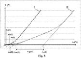
- a force-elongation curve of a strand is produced in accordance with the ISO 6892-1 standard of October 2009.
- the curve obtained comprises three successive parts in this order, moving towards increasing elongations.
- the first part corresponds to bringing the M internal wires together.
- the second part corresponds to bringing the P external son together.
- the third part corresponds to the elastic elongation of the M internal threads and P external threads.
- the tangent to the first part intersects the abscissa axis at a point Asi corresponding to the structural elongation associated with the spacing of the M internal wires.
- the structural elongation of each strand associated with the P external wires is greater than or equal to 0.07%, preferably greater than or equal to 0.09%. In an advantageous embodiment, the structural elongation of each strand associated with the P external wires is greater than or equal to 0.15%, or even greater than or equal to 0.20%, preferably greater than or equal to 0.25%. The higher the structural elongation associated with the P external wires, the greater the spacing of the P external wires at the end of the individual assembly step of each strand, the less the M internal wires are put into compression.
- the structural elongation of each strand is greater than or equal to 0.10%, preferably greater than or equal to 0.15% and more preferably greater than or equal to 0.20%.
- the structural elongation of each strand is greater than or equal to 0.25%, preferably greater than or equal to 0.30% and more preferably greater than or equal to 0.35%.
- the M internal wires and the P external wires are lengthened so that each P external wire has an elongation length greater than an elongation length of each M internal thread.
- the elongation length is the difference between the length of each yarn after and before the step of elongating the yarn.
- the M internal wires and the P external wires are lengthened by imposing an additional twist on each strand after the helical winding of the P external wires around the internal layer.
- each strand has a final torsion equal to the sum of the initial torsion imposed by the assembly of the internal and external layers and of the additional torsion.
- the additional torsion is imposed on each strand by means of a member mounted to rotate about an axis of rotation substantially parallel to the direction of travel of each strand in the member.
- the mounted rotating member comprises at least one pulley around at least a part of which each strand is made to scroll.
- the mounted rotating member comprises at least two pulleys, each following strand, in the member, a path defining at least one loop around at least one of the pulleys.
- the pitch of the assembly is reduced in order to plastically deform the wires of each of the N strands.
- This plastic deformation is retained during the next untwisting step, which gives the cable ventilation which promotes penetrability of the cable by the rubber.
- the substantially zero residual torque corresponds to the fact that the cable is torsionally balanced so that it can be used in the subsequent steps using the cable.
- the torque is expressed in revolutions per meter and corresponds to the number of revolutions that a cable of predetermined length can perform around its main axis when it is left free to move.
- the M internal wires and the P external wires are wound respectively at intermediate pitches p1 'and p2' and during step collective assembly of the N strands, the N strands are wound at a pitch p3 so that the M internal wires and the P external wires respectively have a final pitch p1 and p2 verifying p2 / p2 ' ⁇ p1 / p1', preferably 1.3.p2 / p2 ' ⁇ p1 / p1'.
- the method according to the invention is particularly advantageous in this method of embodiment in which the pitch of the P external threads is shortened more than the pitch of the M internal threads during the collective assembly step and during which the M internal threads are liable to be put strongly in compression if one does not put in implements the method according to the invention.
- Another object of the invention is a multi-strand cable of 1xN structure obtained by a method as defined above in which each strand comprises at most 10 radial outlets for internal wires per meter of strand.
- each strand comprises at most 10 radial outlets of internal wires per meter of strand, preferably at most 5 radial outlets of internal wires per meter of strand and more preferably 2 radial outlets of wires internal per meter of strand.
- a radial outlet of an internal wire corresponds to an internal wire extending radially at least in part radially outside the theoretical circle in which the internal wires should be inscribed.
- a radial exit can take place when an inner wire is partially or totally interposed in the outer layer.
- a radial exit can also take place when an internal thread extends at least partly outside the theoretical circle in which the external threads are inscribed.
- the outer layer of each strand is non-compact.
- a non-compact layer is such that there are spaces between the threads of the layer.
- the outer layer of each strand is unsaturated.
- an unsaturated layer of threads is such that there is sufficient space in this layer to add at least one (X + 1) th thread of the same diameter as the X threads of the layer, several threads then being able to be at least one (X + 1) th thread. contact with each other. Conversely, this layer is said to be saturated if it did not exist enough space in this layer to add at least one (X + 1) th wire of the same diameter as the N wires of the layer.
- the cable according to the invention is particularly advantageous because it does not have radial outlets for internal wires whereas, the external layer being unsaturated, the latter would be facilitated, unlike a cable in which the external layer of each strand would be saturated.
- the unsaturated outer layer thus makes it possible to obtain both excellent penetrability of the rubber in each strand without the latter having no or almost no radial exit of the internal wires.
- the M internal wires being wound helically at the pitch p1, p1 ranges from 3 to 11 mm, preferably from 5 to 9 mm.
- the P external wires being wound helically at the pitch p2, p2 ranges from 6 to 14 mm, preferably from 8 to 12 mm.
- the N strands being wound in a helix at the pitch p3, p3 ranges from 10 to 30 mm, preferably from 15 to 25 mm.
- pitches p1, p2 and p3 can be adapted by a person skilled in the art in order to obtain the desired characteristics for the cable.
- the diameter of the internal and / or external wires ranges from 0.12 mm to 0.50 mm, preferably from 0.25 mm to 0.45 mm and more preferably from 0.30 to 0.40 mm.
- each strand consists of the inner layer and the outer layer.
- each strand is of the two-layer type.
- a further subject of the invention is a tire for a civil engineering vehicle comprising a multi-strand cable as described above.
- the protective reinforcement is interposed radially between the tread and the working reinforcement.
- the protective reinforcement comprising at least one protective ply comprising the or more protective reinforcing elements, the protective reinforcing element (s) form an angle at least equal to 10 °, preferably ranging from 10 ° to 35 ° and more preferably from 15 ° to 30 ° with the circumferential direction of the tire.
- the working reinforcement comprising at least one working ply comprising reinforcing elements, called working elements, the working reinforcing elements form an angle at most equal to 60 °, preferably ranging from 15 ° at 40 ° with the circumferential direction of the tire.
- the crown reinforcement comprises a hooping reinforcement comprising at least one hooping ply.
- each hooping ply comprising reinforcing elements called hooping elements
- the hooping reinforcing elements form an angle at most equal to 10 °, preferably ranging from 5 ° to 10 ° with the circumferential direction of the hoop. pneumatic.
- the hooping frame is arranged radially inside the working frame.
- the tire comprising a carcass reinforcement comprising at least one carcass ply comprising reinforcing elements, called carcass elements, the carcass reinforcing elements form an angle greater than or equal to 65 °, preferably at 80 ° relative to the circumferential direction of the tire.
- the tire has a dimension of W R U type with U ⁇ 35, preferably U ⁇ 49 and more preferably U ⁇ 57. This designation of the tire size complies with the ETRTO (“European Tire and Rim Technical Organization”) nomenclature.
- the wire is a metallic monofilament comprising a core consisting mainly (that is to say for more than 50% of its mass) or entirely (for 100% of its mass) of a metallic material, for example carbon steel, optionally coated with a metallic layer comprising zinc, copper, tin and the alloys of these metals, for example a metallic layer of brass.
- a metallic material for example carbon steel
- the M internal wires and the P external wires are metallic.
- Each wire is preferably steel, more preferably pearlitic (or ferrito-pearlitic) carbon steel, or even stainless steel (by definition, steel comprising at least 11% chromium and at least 50% iron).
- NT normal Tensile
- HT high Tensile
- Rm tensile strength of which is preferably greater than 2000 MPa, more preferably greater than 2500 MPa and less than 3000 MPa (measurement carried out in tension according to the ISO 6892-1 standard of 2009.
- UHT very high resistance
- MT mega high
- any interval of values designated by the expression “between a and b” represents the range of values going from more than a to less than b (that is to say limits a and b excluded) while any interval of values designated by the expression “from a to b” signifies the range of values going from the limit “a” to the limit “b”, that is to say including the strict limits “a” and "B”.
- the tire 10 has a dimension of the WRU type, for example 40.00 R 57 or else 59/80 R 63.
- the tire 10 has a crown 12 reinforced by a crown reinforcement 14, two sidewalls 16 and two beads 18, each of these beads 18 being reinforced with a bead wire 20.
- the crown 12 is surmounted by a tread 22.
- L ' crown reinforcement 14 is arranged radially inside the tread 22.
- a carcass reinforcement 24, arranged radially inside the crown reinforcement 14, is anchored in each bead 18, here wound around each bead wire 20 and comprises an upturn 26 disposed towards the outside of the tire 10 which is shown here mounted on a rim 28.
- the carcass reinforcement 24 comprises at least one carcass ply 30 comprising reinforcing elements, called carcass elements (not shown).
- the carcass reinforcement elements form an angle greater than or equal to 65 °, preferably 80 ° relative to the circumferential direction Z of the tire 10. Examples of such carcass reinforcement elements are described in the documents. EP0602733 or even EP0383716 .
- the tire 10 also comprises a sealing ply 32 made of an elastomer, for example butyl, (commonly called “inner rubber”) which defines the radially internal face 34 of the tire 10 and which is intended to protect the carcass ply. 30 of the diffusion of air coming from the space inside the tire 10.
- a sealing ply 32 made of an elastomer, for example butyl, (commonly called “inner rubber”) which defines the radially internal face 34 of the tire 10 and which is intended to protect the carcass ply. 30 of the diffusion of air coming from the space inside the tire 10.
- the crown reinforcement 14 comprises, radially from the outside towards the inside of the tire 10, a protective reinforcement 36 arranged radially inside the tread 22, a working reinforcement 38 arranged radially on the inside. of the protective frame 36 and a hooping frame 39 arranged radially inside the working frame 38.
- the protective frame 36 is interposed radially between the tread 22 and the working frame 38.
- the protective frame 36 comprises first and second protective plies 42, 44, the first protective ply 42 being arranged radially inside the second protective ply 44.
- the first and second plies protection 42, 44 include so-called protection reinforcing elements (not shown).
- the protective reinforcement elements are arranged side by side parallel to each other in a main direction substantially perpendicular to the general direction in which these reinforcement elements extend.
- the protective reinforcement elements are crossed from one protective ply 42, 44 to the other.
- Each protective reinforcing element, here the general direction in which these reinforcing elements extend makes an angle at least equal to 10 °, preferably ranging from 10 ° to 35 ° and more preferably from 15 ° to 30 ° with the circumferential direction Z of the tire 10.
- the angle is equal to 24 °.
- each protective reinforcement element comprises a multistrand cable 46 of 1xN structure.
- the cable 46 comprises a single layer 48 of N strands 50 wound in a helix at a pitch p3.
- the N strands 50 are wound in a Z or S direction.
- Each strand 50 comprises an internal layer 52 of M internal wires 54 wound in a helix at a pitch p1 and an external layer 56 of P external wires 58 wound in a helix around the internal layer 52 at a pitch p2.
- each strand 50 consists of the inner layer 52 and the outer layer 56.
- Each strand 50 is thus devoid of wrapping wire.
- Each internal 54 and external 58 wire has a diameter ranging from 0.12 mm to 0.50 mm, preferably from 0.25 mm to 0.45 mm and more preferably from 0.30 to 0.40 mm and here equal to 0.35 mm.
- Each internal 54 and external 58 wire is metallic, here in HT (“High Tensile”) grade steel having a breaking strength equal to 2765 MPa. Other grades of steel can of course be used.
- the diameter of the inner threads 54 may be different from the diameter of the outer threads 58.
- the outer layer 56 of each strand 50 is non-compact and unsaturated.
- the winding pitch p1 of the M internal wires 54 ranges from 3 to 11 mm, preferably 5 to 9 mm and is here equal to 6.7 mm.
- the pitch p2 of winding of the P external son 58 ranges from 6 to 14 mm, preferably from 8 to 12 mm and is here equal to 10 mm.
- the winding pitch p3 of the N strands 50 ranges from 10 to 30 mm, preferably from 15 to 25 mm and is here equal to 20 mm.
- the internal wires 54, the external wires 58 and the N strands are wound in the same direction, Z or S.
- the working frame 38 comprises first and second working plies 60, 62, the first working ply 60 being arranged radially inside the second working ply 62.
- the first and second working plies 60, 62 include so-called working reinforcement elements (not shown).
- the working reinforcing elements are arranged side by side parallel to each other in a main direction substantially perpendicular to the general direction in which these reinforcing elements extend.
- the working reinforcement elements are crossed from one working ply 60, 62 to the other.
- Each working reinforcing element, here the general direction in which these reinforcing elements extend makes an angle at most equal to 60 °, preferably ranging from 15 ° to 40 ° with the circumferential direction Z of the tire 10.
- the angle of the reinforcing elements of the first working ply is equal to 19 ° and the angle of the reinforcing elements of the second working ply is equal to 33 °.
- the hooping frame 39 also called the limiter block, the function of which is to partially take up the mechanical inflation stresses, comprises first and second hooping plies 64, 66, the first hooping ply 64 being arranged radially to the inside of the second hooping ply 66.
- Each hooping ply 64, 66 comprises metal hooping reinforcing elements (not shown), for example metal cables as described in FR 2 419 181 or FR 2 419 182 and forming an angle at most equal to 10 °, preferably ranging from 5 ° to 10 ° with the circumferential direction Z of the tire 10. Here the angle is equal to 8 °.
- the hooping reinforcement elements are crossed from one hooping ply 64, 66 to the other.
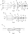
- the installation 68 comprises an installation 70 for manufacturing each strand 50 shown in the figure 5 and an installation 72 for assembling the strands 50 represented on the figure 6 .
- the method according to the invention uses twisting and not cabling.
- the installation 70 for manufacturing each strand 50 comprises, from upstream to downstream in the direction of travel of the strand 50, means 74 for feeding the M internal wires 54, means 76 for assembling the M internal wires by twisting. 54, means 77 for rotating the M assembled internal wires, means 78 for feeding the P external wires 58, means 80 for assembling the P external wires 58 by twisting around the internal layer 52, means 81 for rotating each strand 50, means 82 for extending the M internal wires and the P external wires, means 83 for pulling the strand 50 and means 84 for storing the strand 50.
- the installation 72 for assembling the strands 50 comprises, from upstream to downstream, in the direction of travel of the cable 46, means 86 for supplying the N strands 50, means 88 for assembling by twisting the N strands 50 together, means 89 for rotating the cable 46, means 93 for ventilating and balancing the cable, means 90 for pulling the cable 46 and means 91 for storing the cable 46.
- the supply means 74 of the M internal threads 54 comprise spools 92 for unwinding each internal thread 54.
- the assembly means 76 of the M internal threads comprise a distributor 94 as well as an assembly grain 96 defining a point assembly P1.
- the rotating means 77 comprise two flywheels 97 arranged downstream of the assembly point P1. We therefore speak of rotating feed.
- the means 78 for feeding the P outer yarns 58 comprise spools 98 for unwinding each outer yarn 58.
- the assembly means 80 of the P outer yarns comprise a distributor 100 as well as an assembly grain 102 defining a point of P2 assembly.
- the rotating means 81 comprise two flywheels 103 arranged downstream from the assembly point P2. We are talking therefore rotating reception.
- the extension means 82 of the M internal wires and of the P external wires comprise a member 104 mounted to rotate about an axis of rotation X substantially parallel to the direction D of travel of each strand 50 in the member 104.
- L ' member 104 rotatably mounted comprises at least one pulley 106 around at least a portion of which each strand 50 is scrolled.
- the member 104 mounted rotatably comprises several pulleys, here two pulleys 106.
- each strand 50 follows a path defining at least one loop around at least one of the pulleys 106.
- each strand follows a path defining a lying "8" and is wound around each pulley 106.
- l organ 104 is a two-pulley twister.
- the traction means 83 of each strand 50 comprise one or more capstans 108 and the means 84 for storing each strand 50 comprise a reel 110 for winding each strand 50.
- Each strand 50 is here assembled by twisting.
- the supply means 86 of the N strands 50 comprise coils 112 for unwinding each strand 50.
- the means 88 for assembling the N strands 50 together comprise a distributor 114 as well as an assembly grain 116 defining a point of 'P3 assembly.
- the means 89 for rotating the cable 46 comprise two flywheels 118 arranged downstream from the assembly point P3.
- the aeration and balancing means 93 comprise an upstream twist 124 and a downstream twist 126.
- the cable traction means 90 46 comprise one or more capstans 120 and the cable storage means 91 46 comprise a reel 122 of. cable winding 46.
- the process comprises two assembly steps by twisting.
- the first step is an individual assembly step by twisting each of the N strands 50 implemented by means of the installation 70.
- the second step is a collective assembly step by twisting the N strands 50 implemented by means installation 72.
- the M internal threads 54 are helically wound up at an intermediate pitch p1 ′ to form the internal layer 52.
- p1 ′ 10 mm.
- each P outer yarn 58 has an elongation length greater than an elongation length of each M yarn. internal 54.
- the M internal wires 54 and the P external wires 58 are lengthened by plastic deformation by means of the means 82.
- the M internal wires 54 and the P external wires 58 are lengthened by plastic deformation by imposing a twist additional to each strand 50 after the helical winding of the P external wires 58 around the internal layer 52. Then, each strand 50 thus obtained is stored on the storage means 84.
- the additional torsion is imposed by adjusting the value of the speed of rotation of the rotating member 104 about the axis X. Those skilled in the art will know how to find the value of this speed of rotation as a function of the lengths of elongation desired.
- a tensile tension T1 is applied to the internal layer 52.
- a tension T2 is also applied. in tension to the outer layer 56.
- the tensile stress T1 applied to the inner layer 52 is greater than the tensile stress T2 applied to the outer layer 56.
- N strands 50 are wound in a helix, at pitch p3, to form the cable at pitch p3 as illustrated in figure 6 .
- the N strands 50 are first wound in a helix at pitch p3.
- the upstream twister 124 the N strands 50 are over-twisted so as to obtain a transient pitch p3 ′ ⁇ p3.
- the N strands 50 are untwisted at the pitch p3 so as to obtain a substantially zero residual torque by means of the downstream twister 126.
- the N strands are wound at the pitch p3 so that the M internal wires 54 and the P external wires 58 respectively have a final pitch p1 and p2 verifying p2 / p2 ' ⁇ p1 / p1 ', preferably 1.3.p2 / p2' ⁇ p1 / p1 '.
- p1 6.7 mm
- p2 10 mm.
- a cable of the state of the art C0 and three cables 46, 47 and 49 according to the invention have been compared below.
- the characteristics of these cables C0, 46 and 47 are collated in Table 1 below.
- the cable C0 was manufactured according to a process in accordance with the state of the art, that is to say without a step of lengthening the M internal wires and the P external wires.
- the method of the state of the art is associated with the reference "1".
- Cables 46, 47 and 49 were manufactured according to the invention by implementing a method according to the invention.
- Each cable 46 and 49 is obtained by implementing the method according to the invention described above which is associated with the reference "2" in which during the individual assembly step of each of the N strands, a tensile stress at the inner layer greater than the tensile stress applied to the outer layer.
- the cable 47 is obtained by implementing a method according to the invention, which is associated with the reference "3", in which during the individual assembly step of each of the N strands, the same tension is applied. to the inner layer and to the outer layer.
- the breaking force measurement noted Fm (maximum load in N) is carried out in tension according to the ISO 6892-1 standard of October 2009 on cables directly resulting from the manufacturing process.
- the number of internal wire outlets per meter of strand Ns was measured by disassembling the cable tested and counting, for each strand, the number of internal wire outlets. Thus, for N strands, we obtain a total number of internal wire outlets per meter of cable. By dividing this total number by N, we obtain the number Ns of internal wire outlets per meter of strand.
- the number of internal wire buckling observed per meter of strand Nf was also measured in a similar fashion.
- a buckling corresponds to an abnormally large curvature of a wire without however constituting a radial exit.
- the cables 46, 47 and 49 do not have a variable diameter. All the problems associated with this variation in the diameter of the cable are thus avoided, which makes its manufacture less tedious and reduces its cost.
- each curve has three parts.
- the first part corresponds to bringing the M internal wires together.
- the second part corresponds to bringing the P external son together.
- the third part corresponds to the elastic elongation of the M internal threads and P external threads.
- the tangent to the first part intersects the abscissa axis at a point Asi corresponding to the structural elongation associated with the spacing of the M internal wires.
- the tangent to the second part intersects the abscissa axis at a point Ase, the Ase-Asi difference corresponding to the structural elongation Asm associated with the spacing of the M internal wires.
- the tangent to the third part intersects the x-axis at a point As, the difference As-Ase corresponding to the structural elongation Asp associated with the spacing of the P external wires.
- the spacing of P external wires from the strand of curve II makes it possible to obtain a strand exhibiting much more structural elongation associated with the P external wires than the strand of curve I.
- the structural elongation Asp associated with the P external wires of the strand of curve II is greater than or equal to 0.05%, or even greater than or equal to 0.07%, preferably greater than or equal to 0.09%.
- the structural elongation Asp associated with the P external wires of the strand of curve II is greater than or equal to 0.15%, or even greater than or equal to 0.20%, preferably greater than or equal to 0.25 %.
- Asp 0.31%.
- the structural elongation As of the strand of curve II is much greater than the structural elongation of the strand of curve I. Indeed, the elongation As of the strand of curve II is greater than or equal to 0, 10%, preferably greater than or equal to 0.15% and more preferably greater than or equal to 0.20%. In this case, the elongation As of the strand of curve II is greater than or equal to 0.25%, of preferably greater than or equal to 0.30% and more preferably greater than or equal to 0.35%.
- As 0.43%.
- the cables 46, 47 and 49 allow a minimum gain of 5% in breaking force compared to the cable C0.
- a posteriori the inventors at the origin of the invention discovered that, on the one hand, in the C0 cable, the internal wires coming out between the external wires rubbed between the latter, which caused a drop in the breaking force. cable.
- the inventors emit, a posteriori, the hypothesis according to which, the M internal wires not having any excess length in the cable according to the invention, the latter contribute, when the cable is tensioned. , at the same time as the P external wires to the mechanical resistance of the cable.
- the M internal wires having an excess length do not participate, during a tensioning of the cable, at the same time as the P external wires at the mechanical strength of the cable, which reduces the breaking force of the cable of the state of the art compared to the cable of the invention.
- each strand may also include an intermediate layer, interposed between the internal layer and the external layer, the wires of the intermediate layer being wound helically around the internal layer and the wires of the external layer being wound in a helix around the inner layer.
- the middle layer the cable consists of the inner layer, the middle layer and the outer layer.
Landscapes
- Engineering & Computer Science (AREA)
- Mechanical Engineering (AREA)
- Ropes Or Cables (AREA)
- Tires In General (AREA)
Applications Claiming Priority (2)
| Application Number | Priority Date | Filing Date | Title |
|---|---|---|---|
| FR1551378A FR3032978B1 (fr) | 2015-02-19 | 2015-02-19 | Cable multitorons de structure 1xn pour armature de protection de pneumatique |
| PCT/EP2016/053347 WO2016131862A1 (fr) | 2015-02-19 | 2016-02-17 | Câble multitorons de structure 1xn pour armature de protection de pneumatique |
Publications (2)
| Publication Number | Publication Date |
|---|---|
| EP3259400A1 EP3259400A1 (fr) | 2017-12-27 |
| EP3259400B1 true EP3259400B1 (fr) | 2021-07-07 |
Family
ID=52779966
Family Applications (1)
| Application Number | Title | Priority Date | Filing Date |
|---|---|---|---|
| EP16705143.2A Active EP3259400B1 (fr) | 2015-02-19 | 2016-02-17 | Câble multitorons de structure 1xn pour armature de protection de pneumatique |
Country Status (7)
| Country | Link |
|---|---|
| US (1) | US10704195B2 (enExample) |
| EP (1) | EP3259400B1 (enExample) |
| JP (1) | JP6762309B2 (enExample) |
| KR (1) | KR20170118081A (enExample) |
| CN (1) | CN107580642B (enExample) |
| FR (1) | FR3032978B1 (enExample) |
| WO (1) | WO2016131862A1 (enExample) |
Families Citing this family (16)
| Publication number | Priority date | Publication date | Assignee | Title |
|---|---|---|---|---|
| FR3058926A1 (fr) * | 2016-11-21 | 2018-05-25 | Compagnie Generale Des Etablissements Michelin | Armature de frettage d'un pneumatique pour vehicule lourd de type genie civil |
| FR3060617A1 (fr) | 2016-12-20 | 2018-06-22 | Compagnie Generale Des Etablissements Michelin | Cable multi-torons a deux couches a penetrabilite amelioree |
| FR3060616A1 (fr) | 2016-12-20 | 2018-06-22 | Compagnie Generale Des Etablissements Michelin | Cable multi-torons a deux couches a penetrabilite amelioree |
| WO2019243690A1 (fr) * | 2018-06-20 | 2019-12-26 | Compagnie Generale Des Etablissements Michelin | Câble multi-torons à deux couches à pénétrabilité améliorée |
| CN109295583A (zh) * | 2018-12-03 | 2019-02-01 | 江苏兴达钢帘线股份有限公司 | 一种工程胎带束层用的高伸长率钢丝帘线 |
| FR3092343A1 (fr) * | 2019-02-05 | 2020-08-07 | Compagnie Generale Des Etablissements Michelin | Câble multitorons de structure 1xN à haute énergie à rupture |
| EP4058627B1 (fr) * | 2019-11-15 | 2025-12-31 | Compagnie Generale Des Etablissements Michelin | Câble multi-torons à deux couches avec couche interne gainée à pénétrabilité améliorée |
| JP7737379B2 (ja) | 2020-01-07 | 2025-09-10 | コンパニー ゼネラール デ エタブリッスマン ミシュラン | 改良された破断時エネルギー及び改良された全伸びを有する単層マルチストランドコード |
| FR3106530B1 (fr) * | 2020-01-29 | 2022-01-07 | Michelin & Cie | architecture optimisée de pneumatique de type poids-lourd, agricole ou génie civil |
| FR3136790B1 (fr) * | 2022-06-20 | 2024-05-10 | Michelin & Cie | Câble multi-torons à deux couches de multi-torons |
| FR3136787B1 (fr) | 2022-06-20 | 2024-05-10 | Michelin & Cie | Câble multi-torons à une couche de multi-torons |
| FR3136789B1 (fr) | 2022-06-20 | 2024-05-10 | Michelin & Cie | Câble multi-torons à deux couches de multi-torons |
| FR3136791B1 (fr) | 2022-06-20 | 2024-05-10 | Michelin & Cie | Câble multi-torons à deux couches de multi-torons |
| FR3136788B1 (fr) * | 2022-06-20 | 2024-05-10 | Michelin & Cie | Câble multi-torons à deux couches de multi-torons |
| FR3156457A1 (fr) | 2023-12-12 | 2025-06-13 | Compagnie Generale Des Etablissements Michelin | Câble extrait à une couche à répartition optimisée des fils |
| FR3167582A1 (fr) | 2024-10-17 | 2026-04-24 | Compagnie Generale Des Etablissements Michelin | Pneumatique pour véhicule de type génie civil comprenant des première et deuxième nappes de protection comprenant des éléments de renfort différents |
Family Cites Families (30)
| Publication number | Priority date | Publication date | Assignee | Title |
|---|---|---|---|---|
| FR2419181A1 (fr) | 1978-03-10 | 1979-10-05 | Michelin & Cie | Perfectionnements aux pneumatiques a carcasse radiale |
| FR2419182A1 (fr) | 1978-03-10 | 1979-10-05 | Michelin & Cie | Pneumatique a carcasse radiale, notamment pour engins de genie civil |
| JPS5841638A (ja) * | 1981-09-02 | 1983-03-10 | Kanai Hiroyuki | 二度撚撚線機 |
| US4947636A (en) | 1989-02-13 | 1990-08-14 | The Goodyear Tire & Rubber Company | Metal wire cord for elastomer reinforcement |
| CA2109904C (en) | 1992-12-18 | 2004-09-14 | Pol Bruyneel | Multi-strand steel cord |
| JPH06200491A (ja) * | 1992-12-28 | 1994-07-19 | Bridgestone Metarufua Kk | スチールコードの矯正方法及びその装置 |
| DE69421090T2 (de) * | 1993-12-15 | 2000-01-20 | N.V. Bekaert S.A., Zwevegem | Offene stahlkordkonstruktion |
| JP3529875B2 (ja) * | 1994-02-24 | 2004-05-24 | 株式会社ブリヂストン | ゴム物品補強用スチールコードおよび空気入りラジアルタイヤ |
| ZA9810315B (en) * | 1997-11-27 | 1999-05-18 | Bekaert Sa Nv | Steel cord with spatially waved elements |
| ATE393853T1 (de) * | 2003-07-17 | 2008-05-15 | Bekaert Sa Nv | Offenes lagiges stahlseil mit hoher bruchkraft |
| KR101184642B1 (ko) * | 2003-11-03 | 2012-09-20 | 엔브이 베카에르트 에스에이 | 낮은 구조적 신장도를 가지는 파인 스틸 코드 |
| FR2897076B1 (fr) * | 2006-02-09 | 2008-04-18 | Michelin Soc Tech | Cable composite elastique pour pneumatique. |
| US20100300596A1 (en) * | 2007-11-27 | 2010-12-02 | Bridgestone Corporation | Pneumatic radial tire |
| FR2943951B1 (fr) * | 2009-04-07 | 2012-12-14 | Michelin Soc Tech | Pneumatique pour vehicules lourds comportant une couche d'elements de renforcement circonferentiels. |
| FR2947575B1 (fr) * | 2009-07-03 | 2011-08-19 | Michelin Soc Tech | Cable multitorons dont les torons elementaires sont des cables a deux couches gommes in situ. |
| FR2959517B1 (fr) * | 2010-04-28 | 2012-09-21 | Michelin Soc Tech | Cable metallique multitorons elastique a haute permeabilite. |
| EP2433814B1 (en) | 2010-09-22 | 2014-05-14 | The Goodyear Tire & Rubber Company | Tires with high strengh reinforcement |
| JP5718085B2 (ja) * | 2011-02-17 | 2015-05-13 | 株式会社ブリヂストン | 空気入りタイヤ |
| WO2013107570A1 (en) * | 2012-01-18 | 2013-07-25 | Nv Bekaert Sa | Steel cord with full elastomer penetration |
| CN104040070B (zh) * | 2012-01-18 | 2016-09-21 | 贝卡尔特公司 | 全弹性体渗透的钢帘线 |
| FR2990963B1 (fr) | 2012-05-25 | 2014-12-05 | Michelin & Cie | Cable metallique multi-torons a deux couches. |
| FR2990962B1 (fr) | 2012-05-25 | 2014-06-27 | Michelin & Cie | Procede de fabrication d'un cable metallique multi-torons a deux couches. |
| FR2991630B1 (fr) | 2012-06-07 | 2014-06-27 | Michelin & Cie | Tringle hybride elastique pour pneumatique. |
| FR2991631B1 (fr) | 2012-06-07 | 2015-04-24 | Michelin & Cie | Tringle pliable pour pneumatique. |
| FR2991632B1 (fr) | 2012-06-07 | 2014-06-27 | Michelin & Cie | Tringle hybride allegee pour pneumatique. |
| FR2995822B1 (fr) * | 2012-09-26 | 2014-09-12 | Michelin & Cie | Sommet de pneumatique pour vehicule lourd de type genie civil |
| FR2999614B1 (fr) | 2012-12-14 | 2015-08-21 | Michelin & Cie | Cable metallique a couches a haute penetrabilite |
| FR3020016B1 (fr) | 2014-04-22 | 2016-04-01 | Michelin & Cie | Pneumatique pour vehicule industriel lourd |
| FR3020017B1 (fr) | 2014-04-22 | 2017-06-09 | Michelin & Cie | Pneumatique pour vehicule de genie civil |
| FR3028873B1 (fr) * | 2014-11-25 | 2016-12-23 | Michelin & Cie | Installation de fractionnement |
-
2015
- 2015-02-19 FR FR1551378A patent/FR3032978B1/fr not_active Expired - Fee Related
-
2016
- 2016-02-17 CN CN201680011171.1A patent/CN107580642B/zh active Active
- 2016-02-17 EP EP16705143.2A patent/EP3259400B1/fr active Active
- 2016-02-17 US US15/546,468 patent/US10704195B2/en active Active
- 2016-02-17 JP JP2017543980A patent/JP6762309B2/ja active Active
- 2016-02-17 WO PCT/EP2016/053347 patent/WO2016131862A1/fr not_active Ceased
- 2016-02-17 KR KR1020177022762A patent/KR20170118081A/ko not_active Withdrawn
Non-Patent Citations (1)
| Title |
|---|
| None * |
Also Published As
| Publication number | Publication date |
|---|---|
| JP2018506659A (ja) | 2018-03-08 |
| WO2016131862A1 (fr) | 2016-08-25 |
| CN107580642B (zh) | 2020-10-09 |
| FR3032978A1 (fr) | 2016-08-26 |
| EP3259400A1 (fr) | 2017-12-27 |
| JP6762309B2 (ja) | 2020-09-30 |
| US10704195B2 (en) | 2020-07-07 |
| US20180010294A1 (en) | 2018-01-11 |
| KR20170118081A (ko) | 2017-10-24 |
| CN107580642A (zh) | 2018-01-12 |
| FR3032978B1 (fr) | 2017-10-27 |
Similar Documents
| Publication | Publication Date | Title |
|---|---|---|
| EP3259400B1 (fr) | Câble multitorons de structure 1xn pour armature de protection de pneumatique | |
| EP3224406B1 (fr) | Procede de fractionnement | |
| EP3224407B1 (fr) | Installation de fractionnement | |
| EP3921466B1 (fr) | Câble multitorons de structure 1xn à haute énergie à rupture | |
| EP4061996B1 (fr) | Câble multi-torons à deux couches à énergie de rupture surfacique améliorée | |
| EP3303686B1 (fr) | Procédé d'assemblage comprenant une étape de préformation | |
| EP3303687B1 (fr) | Installation de fabrication d'un assemblage | |
| EP4172406A1 (fr) | Câble multi-torons à deux couches à endurance sous flexion améliorée | |
| EP3732064B1 (fr) | Armature de frettage d'un pneumatique pour vehicule lourd de type genie civil | |
| EP4045299B1 (fr) | Pneumatique presentant une uniformite amelioree et son procede de fabrication | |
| EP3700849B1 (fr) | Procédé de fabrication d'un composite élastomèrique | |
| FR2935294A1 (fr) | Pneumatique pour vehicules lourds dont l'armature de sommet comporte une bande complexe | |
| EP4172407B1 (fr) | Câble multi-torons à deux couches à endurance sous flexion améliorée | |
| WO2021260304A1 (fr) | Câble multi-torons à deux couches à endurance sous flexion améliorée | |
| EP4058628B1 (fr) | Câble multi-torons à deux couches avec couche interne gainée à rendement amélioré | |
| EP4058629B1 (fr) | Câbles métalliques à deux couches avec couche interne gainée à rendement amélioré | |
| WO2025185955A1 (fr) | Câble compact à résistance mécanique élevée comprenant des fils fins | |
| EP4448303A1 (fr) | Câble multi-torons à deux couches à endurance sous flexion améliorée | |
| EP4334523A1 (fr) | Câble multi-torons à deux couches à énergie de rupture surfacique améliorée | |
| FR3122674A1 (fr) | Câble multi-torons à deux couches à énergie de rupture surfacique améliorée | |
| FR3090704A1 (fr) | Procédé de fabrication d’un câble multi-torons à deux couches | |
| FR3090703A1 (fr) | Procédé de fabrication d’un câble multi-torons à deux couches |
Legal Events
| Date | Code | Title | Description |
|---|---|---|---|
| STAA | Information on the status of an ep patent application or granted ep patent |
Free format text: STATUS: THE INTERNATIONAL PUBLICATION HAS BEEN MADE |
|
| PUAI | Public reference made under article 153(3) epc to a published international application that has entered the european phase |
Free format text: ORIGINAL CODE: 0009012 |
|
| STAA | Information on the status of an ep patent application or granted ep patent |
Free format text: STATUS: REQUEST FOR EXAMINATION WAS MADE |
|
| 17P | Request for examination filed |
Effective date: 20170919 |
|
| AK | Designated contracting states |
Kind code of ref document: A1 Designated state(s): AL AT BE BG CH CY CZ DE DK EE ES FI FR GB GR HR HU IE IS IT LI LT LU LV MC MK MT NL NO PL PT RO RS SE SI SK SM TR |
|
| AX | Request for extension of the european patent |
Extension state: BA ME |
|
| DAV | Request for validation of the european patent (deleted) | ||
| DAX | Request for extension of the european patent (deleted) | ||
| RAP1 | Party data changed (applicant data changed or rights of an application transferred) |
Owner name: COMPAGNIE GENERALE DES ETABLISSEMENTS MICHELIN |
|
| STAA | Information on the status of an ep patent application or granted ep patent |
Free format text: STATUS: EXAMINATION IS IN PROGRESS |
|
| 17Q | First examination report despatched |
Effective date: 20190618 |
|
| GRAP | Despatch of communication of intention to grant a patent |
Free format text: ORIGINAL CODE: EPIDOSNIGR1 |
|
| STAA | Information on the status of an ep patent application or granted ep patent |
Free format text: STATUS: GRANT OF PATENT IS INTENDED |
|
| INTG | Intention to grant announced |
Effective date: 20210325 |
|
| GRAS | Grant fee paid |
Free format text: ORIGINAL CODE: EPIDOSNIGR3 |
|
| GRAA | (expected) grant |
Free format text: ORIGINAL CODE: 0009210 |
|
| STAA | Information on the status of an ep patent application or granted ep patent |
Free format text: STATUS: THE PATENT HAS BEEN GRANTED |
|
| AK | Designated contracting states |
Kind code of ref document: B1 Designated state(s): AL AT BE BG CH CY CZ DE DK EE ES FI FR GB GR HR HU IE IS IT LI LT LU LV MC MK MT NL NO PL PT RO RS SE SI SK SM TR |
|
| REG | Reference to a national code |
Ref country code: GB Ref legal event code: FG4D Free format text: NOT ENGLISH |
|
| REG | Reference to a national code |
Ref country code: AT Ref legal event code: REF Ref document number: 1408716 Country of ref document: AT Kind code of ref document: T Effective date: 20210715 |
|
| REG | Reference to a national code |
Ref country code: DE Ref legal event code: R096 Ref document number: 602016060270 Country of ref document: DE |
|
| REG | Reference to a national code |
Ref country code: IE Ref legal event code: FG4D Free format text: LANGUAGE OF EP DOCUMENT: FRENCH |
|
| REG | Reference to a national code |
Ref country code: LT Ref legal event code: MG9D |
|
| REG | Reference to a national code |
Ref country code: NL Ref legal event code: MP Effective date: 20210707 |
|
| REG | Reference to a national code |
Ref country code: AT Ref legal event code: MK05 Ref document number: 1408716 Country of ref document: AT Kind code of ref document: T Effective date: 20210707 |
|
| PG25 | Lapsed in a contracting state [announced via postgrant information from national office to epo] |
Ref country code: SE Free format text: LAPSE BECAUSE OF FAILURE TO SUBMIT A TRANSLATION OF THE DESCRIPTION OR TO PAY THE FEE WITHIN THE PRESCRIBED TIME-LIMIT Effective date: 20210707 Ref country code: RS Free format text: LAPSE BECAUSE OF FAILURE TO SUBMIT A TRANSLATION OF THE DESCRIPTION OR TO PAY THE FEE WITHIN THE PRESCRIBED TIME-LIMIT Effective date: 20210707 Ref country code: LT Free format text: LAPSE BECAUSE OF FAILURE TO SUBMIT A TRANSLATION OF THE DESCRIPTION OR TO PAY THE FEE WITHIN THE PRESCRIBED TIME-LIMIT Effective date: 20210707 Ref country code: AT Free format text: LAPSE BECAUSE OF FAILURE TO SUBMIT A TRANSLATION OF THE DESCRIPTION OR TO PAY THE FEE WITHIN THE PRESCRIBED TIME-LIMIT Effective date: 20210707 Ref country code: BG Free format text: LAPSE BECAUSE OF FAILURE TO SUBMIT A TRANSLATION OF THE DESCRIPTION OR TO PAY THE FEE WITHIN THE PRESCRIBED TIME-LIMIT Effective date: 20211007 Ref country code: NL Free format text: LAPSE BECAUSE OF FAILURE TO SUBMIT A TRANSLATION OF THE DESCRIPTION OR TO PAY THE FEE WITHIN THE PRESCRIBED TIME-LIMIT Effective date: 20210707 Ref country code: PT Free format text: LAPSE BECAUSE OF FAILURE TO SUBMIT A TRANSLATION OF THE DESCRIPTION OR TO PAY THE FEE WITHIN THE PRESCRIBED TIME-LIMIT Effective date: 20211108 Ref country code: NO Free format text: LAPSE BECAUSE OF FAILURE TO SUBMIT A TRANSLATION OF THE DESCRIPTION OR TO PAY THE FEE WITHIN THE PRESCRIBED TIME-LIMIT Effective date: 20211007 Ref country code: ES Free format text: LAPSE BECAUSE OF FAILURE TO SUBMIT A TRANSLATION OF THE DESCRIPTION OR TO PAY THE FEE WITHIN THE PRESCRIBED TIME-LIMIT Effective date: 20210707 Ref country code: FI Free format text: LAPSE BECAUSE OF FAILURE TO SUBMIT A TRANSLATION OF THE DESCRIPTION OR TO PAY THE FEE WITHIN THE PRESCRIBED TIME-LIMIT Effective date: 20210707 Ref country code: HR Free format text: LAPSE BECAUSE OF FAILURE TO SUBMIT A TRANSLATION OF THE DESCRIPTION OR TO PAY THE FEE WITHIN THE PRESCRIBED TIME-LIMIT Effective date: 20210707 |
|
| PG25 | Lapsed in a contracting state [announced via postgrant information from national office to epo] |
Ref country code: PL Free format text: LAPSE BECAUSE OF FAILURE TO SUBMIT A TRANSLATION OF THE DESCRIPTION OR TO PAY THE FEE WITHIN THE PRESCRIBED TIME-LIMIT Effective date: 20210707 Ref country code: LV Free format text: LAPSE BECAUSE OF FAILURE TO SUBMIT A TRANSLATION OF THE DESCRIPTION OR TO PAY THE FEE WITHIN THE PRESCRIBED TIME-LIMIT Effective date: 20210707 Ref country code: GR Free format text: LAPSE BECAUSE OF FAILURE TO SUBMIT A TRANSLATION OF THE DESCRIPTION OR TO PAY THE FEE WITHIN THE PRESCRIBED TIME-LIMIT Effective date: 20211008 |
|
| REG | Reference to a national code |
Ref country code: DE Ref legal event code: R097 Ref document number: 602016060270 Country of ref document: DE |
|
| PG25 | Lapsed in a contracting state [announced via postgrant information from national office to epo] |
Ref country code: DK Free format text: LAPSE BECAUSE OF FAILURE TO SUBMIT A TRANSLATION OF THE DESCRIPTION OR TO PAY THE FEE WITHIN THE PRESCRIBED TIME-LIMIT Effective date: 20210707 |
|
| PLBE | No opposition filed within time limit |
Free format text: ORIGINAL CODE: 0009261 |
|
| STAA | Information on the status of an ep patent application or granted ep patent |
Free format text: STATUS: NO OPPOSITION FILED WITHIN TIME LIMIT |
|
| PG25 | Lapsed in a contracting state [announced via postgrant information from national office to epo] |
Ref country code: SM Free format text: LAPSE BECAUSE OF FAILURE TO SUBMIT A TRANSLATION OF THE DESCRIPTION OR TO PAY THE FEE WITHIN THE PRESCRIBED TIME-LIMIT Effective date: 20210707 Ref country code: SK Free format text: LAPSE BECAUSE OF FAILURE TO SUBMIT A TRANSLATION OF THE DESCRIPTION OR TO PAY THE FEE WITHIN THE PRESCRIBED TIME-LIMIT Effective date: 20210707 Ref country code: RO Free format text: LAPSE BECAUSE OF FAILURE TO SUBMIT A TRANSLATION OF THE DESCRIPTION OR TO PAY THE FEE WITHIN THE PRESCRIBED TIME-LIMIT Effective date: 20210707 Ref country code: EE Free format text: LAPSE BECAUSE OF FAILURE TO SUBMIT A TRANSLATION OF THE DESCRIPTION OR TO PAY THE FEE WITHIN THE PRESCRIBED TIME-LIMIT Effective date: 20210707 Ref country code: CZ Free format text: LAPSE BECAUSE OF FAILURE TO SUBMIT A TRANSLATION OF THE DESCRIPTION OR TO PAY THE FEE WITHIN THE PRESCRIBED TIME-LIMIT Effective date: 20210707 Ref country code: AL Free format text: LAPSE BECAUSE OF FAILURE TO SUBMIT A TRANSLATION OF THE DESCRIPTION OR TO PAY THE FEE WITHIN THE PRESCRIBED TIME-LIMIT Effective date: 20210707 |
|
| 26N | No opposition filed |
Effective date: 20220408 |
|
| PG25 | Lapsed in a contracting state [announced via postgrant information from national office to epo] |
Ref country code: IT Free format text: LAPSE BECAUSE OF FAILURE TO SUBMIT A TRANSLATION OF THE DESCRIPTION OR TO PAY THE FEE WITHIN THE PRESCRIBED TIME-LIMIT Effective date: 20210707 |
|
| PG25 | Lapsed in a contracting state [announced via postgrant information from national office to epo] |
Ref country code: MC Free format text: LAPSE BECAUSE OF FAILURE TO SUBMIT A TRANSLATION OF THE DESCRIPTION OR TO PAY THE FEE WITHIN THE PRESCRIBED TIME-LIMIT Effective date: 20210707 |
|
| REG | Reference to a national code |
Ref country code: CH Ref legal event code: PL |
|
| REG | Reference to a national code |
Ref country code: BE Ref legal event code: MM Effective date: 20220228 |
|
| GBPC | Gb: european patent ceased through non-payment of renewal fee |
Effective date: 20220217 |
|
| PG25 | Lapsed in a contracting state [announced via postgrant information from national office to epo] |
Ref country code: LU Free format text: LAPSE BECAUSE OF NON-PAYMENT OF DUE FEES Effective date: 20220217 |
|
| PG25 | Lapsed in a contracting state [announced via postgrant information from national office to epo] |
Ref country code: LI Free format text: LAPSE BECAUSE OF NON-PAYMENT OF DUE FEES Effective date: 20220228 Ref country code: IE Free format text: LAPSE BECAUSE OF NON-PAYMENT OF DUE FEES Effective date: 20220217 Ref country code: GB Free format text: LAPSE BECAUSE OF NON-PAYMENT OF DUE FEES Effective date: 20220217 Ref country code: CH Free format text: LAPSE BECAUSE OF NON-PAYMENT OF DUE FEES Effective date: 20220228 |
|
| PG25 | Lapsed in a contracting state [announced via postgrant information from national office to epo] |
Ref country code: BE Free format text: LAPSE BECAUSE OF NON-PAYMENT OF DUE FEES Effective date: 20220228 |
|
| PG25 | Lapsed in a contracting state [announced via postgrant information from national office to epo] |
Ref country code: HU Free format text: LAPSE BECAUSE OF FAILURE TO SUBMIT A TRANSLATION OF THE DESCRIPTION OR TO PAY THE FEE WITHIN THE PRESCRIBED TIME-LIMIT; INVALID AB INITIO Effective date: 20160217 |
|
| PG25 | Lapsed in a contracting state [announced via postgrant information from national office to epo] |
Ref country code: MK Free format text: LAPSE BECAUSE OF FAILURE TO SUBMIT A TRANSLATION OF THE DESCRIPTION OR TO PAY THE FEE WITHIN THE PRESCRIBED TIME-LIMIT Effective date: 20210707 Ref country code: CY Free format text: LAPSE BECAUSE OF FAILURE TO SUBMIT A TRANSLATION OF THE DESCRIPTION OR TO PAY THE FEE WITHIN THE PRESCRIBED TIME-LIMIT Effective date: 20210707 |
|
| PG25 | Lapsed in a contracting state [announced via postgrant information from national office to epo] |
Ref country code: MT Free format text: LAPSE BECAUSE OF FAILURE TO SUBMIT A TRANSLATION OF THE DESCRIPTION OR TO PAY THE FEE WITHIN THE PRESCRIBED TIME-LIMIT Effective date: 20210707 |
|
| PG25 | Lapsed in a contracting state [announced via postgrant information from national office to epo] |
Ref country code: TR Free format text: LAPSE BECAUSE OF FAILURE TO SUBMIT A TRANSLATION OF THE DESCRIPTION OR TO PAY THE FEE WITHIN THE PRESCRIBED TIME-LIMIT Effective date: 20210707 |
|
| PGFP | Annual fee paid to national office [announced via postgrant information from national office to epo] |
Ref country code: DE Payment date: 20260218 Year of fee payment: 11 |
|
| PGFP | Annual fee paid to national office [announced via postgrant information from national office to epo] |
Ref country code: FR Payment date: 20260218 Year of fee payment: 11 |