EP3258757A1 - Unterflurverteiler für elektrische und/oder elektronische einrichtungen - Google Patents
Unterflurverteiler für elektrische und/oder elektronische einrichtungen Download PDFInfo
- Publication number
- EP3258757A1 EP3258757A1 EP17000992.2A EP17000992A EP3258757A1 EP 3258757 A1 EP3258757 A1 EP 3258757A1 EP 17000992 A EP17000992 A EP 17000992A EP 3258757 A1 EP3258757 A1 EP 3258757A1
- Authority
- EP
- European Patent Office
- Prior art keywords
- chamber
- cold air
- shaft
- hood
- electrical
- Prior art date
- Legal status (The legal status is an assumption and is not a legal conclusion. Google has not performed a legal analysis and makes no representation as to the accuracy of the status listed.)
- Granted
Links
Images


Classifications
-
- H—ELECTRICITY
- H05—ELECTRIC TECHNIQUES NOT OTHERWISE PROVIDED FOR
- H05K—PRINTED CIRCUITS; CASINGS OR CONSTRUCTIONAL DETAILS OF ELECTRIC APPARATUS; MANUFACTURE OF ASSEMBLAGES OF ELECTRICAL COMPONENTS
- H05K7/00—Constructional details common to different types of electric apparatus
- H05K7/20—Modifications to facilitate cooling, ventilating, or heating
- H05K7/20009—Modifications to facilitate cooling, ventilating, or heating using a gaseous coolant in electronic enclosures
- H05K7/20136—Forced ventilation, e.g. by fans
-
- H—ELECTRICITY
- H02—GENERATION; CONVERSION OR DISTRIBUTION OF ELECTRIC POWER
- H02B—BOARDS, SUBSTATIONS OR SWITCHING ARRANGEMENTS FOR THE SUPPLY OR DISTRIBUTION OF ELECTRIC POWER
- H02B1/00—Frameworks, boards, panels, desks, casings; Details of substations or switching arrangements
- H02B1/26—Casings; Parts thereof or accessories therefor
- H02B1/28—Casings; Parts thereof or accessories therefor dustproof, splashproof, drip-proof, waterproof or flameproof
-
- H—ELECTRICITY
- H02—GENERATION; CONVERSION OR DISTRIBUTION OF ELECTRIC POWER
- H02B—BOARDS, SUBSTATIONS OR SWITCHING ARRANGEMENTS FOR THE SUPPLY OR DISTRIBUTION OF ELECTRIC POWER
- H02B1/00—Frameworks, boards, panels, desks, casings; Details of substations or switching arrangements
- H02B1/56—Cooling; Ventilation
-
- H—ELECTRICITY
- H02—GENERATION; CONVERSION OR DISTRIBUTION OF ELECTRIC POWER
- H02G—INSTALLATION OF ELECTRIC CABLES OR LINES, OR OF COMBINED OPTICAL AND ELECTRIC CABLES OR LINES
- H02G3/00—Installations of electric cables or lines or protective tubing therefor in or on buildings, equivalent structures or vehicles
- H02G3/02—Details
- H02G3/03—Cooling
-
- H—ELECTRICITY
- H02—GENERATION; CONVERSION OR DISTRIBUTION OF ELECTRIC POWER
- H02G—INSTALLATION OF ELECTRIC CABLES OR LINES, OR OF COMBINED OPTICAL AND ELECTRIC CABLES OR LINES
- H02G3/00—Installations of electric cables or lines or protective tubing therefor in or on buildings, equivalent structures or vehicles
- H02G3/02—Details
- H02G3/08—Distribution boxes; Connection or junction boxes
- H02G3/18—Distribution boxes; Connection or junction boxes providing line outlets
- H02G3/185—Floor outlets and access cups
-
- H—ELECTRICITY
- H02—GENERATION; CONVERSION OR DISTRIBUTION OF ELECTRIC POWER
- H02G—INSTALLATION OF ELECTRIC CABLES OR LINES, OR OF COMBINED OPTICAL AND ELECTRIC CABLES OR LINES
- H02G3/00—Installations of electric cables or lines or protective tubing therefor in or on buildings, equivalent structures or vehicles
- H02G3/28—Installations of cables, lines, or separate protective tubing therefor in conduits or ducts pre-established in walls, ceilings or floors
- H02G3/283—Installations of cables, lines, or separate protective tubing therefor in conduits or ducts pre-established in walls, ceilings or floors in floors
-
- H—ELECTRICITY
- H02—GENERATION; CONVERSION OR DISTRIBUTION OF ELECTRIC POWER
- H02G—INSTALLATION OF ELECTRIC CABLES OR LINES, OR OF COMBINED OPTICAL AND ELECTRIC CABLES OR LINES
- H02G9/00—Installations of electric cables or lines in or on the ground or water
- H02G9/10—Installations of electric cables or lines in or on the ground or water in cable chambers, e.g. in manhole or in handhole
-
- H—ELECTRICITY
- H05—ELECTRIC TECHNIQUES NOT OTHERWISE PROVIDED FOR
- H05K—PRINTED CIRCUITS; CASINGS OR CONSTRUCTIONAL DETAILS OF ELECTRIC APPARATUS; MANUFACTURE OF ASSEMBLAGES OF ELECTRICAL COMPONENTS
- H05K5/00—Casings, cabinets or drawers for electric apparatus
-
- H—ELECTRICITY
- H05—ELECTRIC TECHNIQUES NOT OTHERWISE PROVIDED FOR
- H05K—PRINTED CIRCUITS; CASINGS OR CONSTRUCTIONAL DETAILS OF ELECTRIC APPARATUS; MANUFACTURE OF ASSEMBLAGES OF ELECTRICAL COMPONENTS
- H05K7/00—Constructional details common to different types of electric apparatus
- H05K7/20—Modifications to facilitate cooling, ventilating, or heating
- H05K7/20009—Modifications to facilitate cooling, ventilating, or heating using a gaseous coolant in electronic enclosures
- H05K7/20136—Forced ventilation, e.g. by fans
- H05K7/20145—Means for directing air flow, e.g. ducts, deflectors, plenum or guides
Definitions
- the invention relates to an underfloor distributor for electrical and / or electronic devices, in particular telecommunications, with an underfloor in the ground installable shaft having at least a lid and an airtight hood, which consists of a horizontal position in the shaft in which the bottom of the Hood is open, is arranged pivotally in a vertical position upwards, and in which the electrical and / or electronic devices are arranged.
- the hood can be folded up into the preferably vertical position, so that the electrical and / or electronic devices arranged therein are accessible to a fitter for installation, operating and maintenance work.
- In the horizontal starting position protects the airtight hood in the manner of a diving bell, the components arranged therein at a water penetration into the shaft from contact with the water, which can penetrate only in a very low height in the hood below.
- the present invention has for its object to effectively dissipate these harmful heat and thereby maintain the protection against the ingress of water. This object is achieved by the features of claim 1.
- the invention provides that in the hood, a housing is fixed, in which the electrical and / or electronic devices are cooled.
- the housing is attached to the hood so that the housing is pivoted with the hood when the hood is flipped up.
- the housing includes a cold air chamber and at least one further separate chamber in fluid communication with the cold air chamber.
- the cold air chamber is preferably at least one fan, preferably a plurality of fans arranged, suck the cold supply air, which comes from the vicinity of the shaft, in the cold air chamber.
- the fan (s) press the cold air into the at least one separate chamber in which electrical and / or electronic devices are located, the cold air flowing under pressure through the at least one separate chamber cooling the electrical and / or electronic devices.
- the thus heated air exits the separate chamber and in the further course down from the hood and leaves the shaft through openings in the at least one cover of the shaft.
- the at least one separate further chamber is preferably attached laterally to the cold air chamber, which is provided with great advantage that on both sides of the cold air chamber each have a separate further chamber is attached, both with the cold air chamber through openings, in particular Slots in the side walls of the cold air chamber, in fluid communication with this.
- the cold air chamber in the bottom region has a preferably circular opening into which a pipe opens, through which the cold air is supplied by the at least one fan, preferably two or three juxtaposed fans is sucked, which are arranged in the cold air chamber.
- the fans push the cold air upwards, whereby they pass through the two-sided slots arranged in the upper area into the side chambers and flow through them downwards.
- the air cools the superimposed electrical and / or electronic components, which are preferably provided with cooling fins, wherein the thereby heated air flows out of the bottom open side chambers.
- the heated air flows out of the open hood at the bottom due to the pressure generated by the fans and leaves the shaft via the outlet openings distributed over the cover.
- the housing provided for cooling the electrical and / or electronic components is pivotable together with the hood, wherein in the folded-up state, the components are accessible to an installer through the open bottom of the lateral chambers.
- a smooth entry or exit of the tube in or out of the opening of the cold air chamber is preferably achieved in that the opening of the bottom portion of the cold air chamber is formed in the horizontal state of the hood in an inclined to the horizontal bottom wall of the cold air chamber , And that the holder fixed the end of the cold air pipe according inclined. As a result, the end of the cold air pipe can exit smoothly from the opening and re-enter the opening without the need for a fitter's hand.
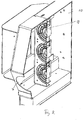
- the shaft can have one or more lids. At least one opening for entry of cold air into the shaft is formed at an edge area of the or one of the lids, wherein the area under this at least one opening is shielded by sheets from the remaining shaft interior, for example, so that the heated air can not enter the area , In this shielded cold air area projects for another proposal, the end of the cold air pipe
- the outlet openings for the heated air are preferably distributed over the lid surface.
- the underfloor distributor according to the invention cools the electrical / electronic components very effectively in the cooling housing provided for this purpose with low energy consumption, with which cold air is sucked into the housing and is pressed extremely effectively through narrow air ducts in the lateral chambers past the electrical / electronic components, wherein the heated air escapes from the shaft without further aids.
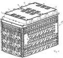
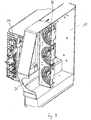
- FIG. 1 shows a plastic shaft 1, which is closed by two covers 2.
- the Indian FIG. 1 left lid contains an area, for example, three Openings 3 for entry of cold air.
- the two covers still contain three areas, for example, with a total of nine openings 4 for warm air.
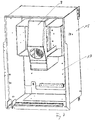
- the central vertical section of the FIG. 2 discloses a tube 5 leading from the left upper end region to the bottom 6 of the well to which a subsequent horizontal section of the tube 5 is attached, whereupon the tube 5 extends upwards and into an opening 7 in the bottom region, generally designated 8 designated cooling housing opens.
- the cooling housing 8 Through the pipe 5 cold air from the environment of the shaft 1 is introduced into the cooling housing 8 in the manner described in more detail below.
- three fans 9 are arranged side by side, which fill substantially the entire cross section of a cold air chamber 10 of the cooling housing 8.
- the angled upper end portion 11 of the tube 5 is arranged in a shielded by sheets 12 from the remaining interior of the shaft 1 region 13, is sucked into the cold ambient air through the openings 3 in the lid.
- FIG. 3 shows that the lower end portion of the tube 5 is fixed by a holder 14 in an oblique position.
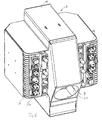
- the cooling housing 8 is fixed to the rear wall of the airtight hood 15, which in the installed position in the shaft 1 according to the FIGS. 2 to 4 arranged horizontally as the upper wall and open at the bottom.
- the hood 15 prevents water entering the well 1, that water enters the hood 15 to electrical / electronic components 16 which are mounted in the cooling housing 8.
- the cooling housing 8 is thus pivotable together with the hood 15.
- the FIGS. 5 to 9 show representations of the cooling housing 8 in an upwardly pivoted state.
- the cooling housing 8 has a central cold air chamber 10, which in the installed position has the above-mentioned opening 7, in which the lower end of the tube engages smoothly.
- a further chamber 17 a is fixed in each case, in which a kit of electrical / electronic components 16 with Cooling ribs on top of each other (in the representations of FIGS. 5 to 9 ) are arranged.
- the further chambers 17a are in the folded state of the hood 15 open to the front, so that the electrical / electronic component for a mechanic are easily accessible. In the starting position in the shaft, the open side of the lateral chambers 17a is below.
- the cold air chamber 10 communicates with the side chambers 17a through slots 19 in the side walls in fluid communication.
- Baffles 20 in the lateral chambers 17a contribute to the fact that the cold air flows from the cold air chamber 10 smoothly through the arrangement of the electrical / electronic components 16 and this effectively cools.
- the cold air in the cold-air chamber 10 thus first flows upward, flows through lateral slots in the side chambers 17a and down there, where then the heated air at the bottom from the side chambers 17a and then from the hood 15 and the openings 4 in the lids 2 exits into the environment.
Landscapes
- Engineering & Computer Science (AREA)
- Microelectronics & Electronic Packaging (AREA)
- Architecture (AREA)
- Civil Engineering (AREA)
- Structural Engineering (AREA)
- Physics & Mathematics (AREA)
- Thermal Sciences (AREA)
- Power Engineering (AREA)
- Cooling Or The Like Of Electrical Apparatus (AREA)
Abstract
Description
- Die Erfindung betrifft einen Unterflurverteiler für elektrische und/oder elektronische Einrichtungen, insbesondere der Telekommunikation, mit einem Unterflur in den Boden einbaubaren Schacht, der wenigstens einen Deckel und eine luftdichte Haube aufweist, die aus einer horizontalen Lage in dem Schacht, bei der die Unterseite der Haube offen ist, in eine vertikale Lage nach oben schwenkbar angeordnet ist, und in der die elektrischen und/oder elektronischen Einrichtungen angeordnet sind. Die Haube ist in die bevorzugt vertikal Lage hochklappbar, damit die darin angeordneten elektrischen und/oder elektronischen Einrichtungen für einen Monteur zu Installations-, Bedienungs- und Wartungsarbeiten zugänglich sind. In der horizontalen Ausgangslage schützt die luftdichte Haube nach Art einer Tauchglocke die darin angeordneten Komponenten bei einem Wassereinbruch in den Schacht vor der Berührung mit dem Wasser, das nur in einer sehr geringen Höhe in die Haube unten eindringen kann.
- Bei einem Betrieb der elektrischen/elektronischen Komponenten entsteht beispielsweise durch eine hohle Belegung von Teilnehmem bei Telekommunikationseinrichtungen eine große Verlustleistung, die zu so hohen Temperaturen unter der luftdichten Haube führen kann, das einzelne oder alle elektrischen und/oder elektronischen Komponenten ausfallen und sogar dauerhaft beschädigt werden können.
- Der vorliegenden Erfindung liegt die Aufgabe zugrunde, diese schädliche Wärme wirkungsvoll abzuführen und dabei den Schutz vor eindringendem Wasser beizubehalten. Diese Aufgabe wird erfindungsgemäß durch die Merkmale des Patentanspruchs 1 gelöst.
- Vorteilhafte Ausgestaltungen der Erfindung sind in den Unteransprüchen gekennzeichnet.
- Die Erfindung sieht vor, dass in der Haube ein Gehäuse befestigt ist, in dem die elektrischen und/oder elektronischen Einrichtungen gekühlt werden. Das Gehäuse ist so an der Haube befestigt, dass das Gehäuse mit der Haube verschwenkt wird, wenn die Haube nach oben geklappt wird.
- Das Gehäuse enthält eine Kaltluft-Kammer und wenigstens eine weitere getrennte Kammer, die mit der Kaltluft-Kammer in Strömungsverbindung steht. In der Kaltluft-Kammer ist bevorzugt wenigstens ein Lüfter, bevorzugt mehrere Lüfter angeordnet, die kalte Zuluft, die aus der Umgebung des Schachtes stammt, in die Kaltluftkammer ansaugen. Der bzw. die Lüfter drücken die Kaltluft in die wenigstens eine getrennte Kammer, in der elektrische und/oder elektronische Einrichtungen angeordnet sind, wobei die unter Druck die wenigstens eine getrennte Kammer durchströmende Kaltluft die elektrischen und/oder elektronischen Einrichtungen kühlt. Die so erwärmte Luft tritt aus der getrennten Kammer und im weiteren Verlauf unten aus der Haube aus und verlässt den Schacht durch Öffnungen in dem wenigstens einen Deckel des Schachtes.
- Die wenigstens eine getrennte weitere Kammer ist bevorzugt seitlich an der Kaltluft-Kammer befestigt, wobei mit großem Vorteil vorgesehen ist, dass an beiden Seiten der Kaltluft-Kammer jeweils eine getrennte weitere Kammer befestigt ist, die beide mit der Kaltluft-Kammer durch Öffnungen, insbesondere Schlitze in den Seitenwänden der Kaltluft-Kammer, mit dieser in Strömungsverbindung stehen.
- In der horizontalen Einbaulage der Haube hat die Kaltluft-Kammer im Bodenbereich eine vorzugsweise kreisrunde Öffnung, in die ein Rohr einmündet, durch das die Kaltluft zugeführt wird, die von dem wenigstens einen Lüfter, bevorzugt von zwei oder drei nebeneinander angeordneten Lüftern angesaugt wird, die in der Kaltluft-Kammer angeordnet sind. Die Lüfter drücken die Kaltluft nach oben, wobei sie durch im oberen Bereich angeordnete, beidseitige Schlitze oben in die seitlichen Kammern eintreten und diese nach unten durchströmen. Dabei kühlt die Luft die übereinander angeordneten elektrischen und/oder elektronischen Komponenten, die vorzugsweise mit Kühlrippen versehen sind, wobei die dabei erwärmte Luft aus den unten offenen seitlichen Kammern ausströmt. Die erwärmte Luft strömt infolge des von den Lüftern erzeugten Drucks unten aus der offenen Haube aus und verlässt den Schacht über die über den Deckel verteilten Austrittsöffnungen.
- Wie oben erwähnt, ist das zur Kühlung der elektrische und/oder elektronischen Komponenten vorgesehene Gehäuse gemeinsam mit der Haube verschwenkbar, wobei im hoch geklappten Zustand die Komponenten durch den offenen Boden der seitlichen Kammern für einen Monteur zugänglich sind. Beim Hochklappen der Haube und damit des Gehäuses wird dessen Verbindung mit dem am Boden des Schachtes fixierten Schlauch getrennt. Hierzu ist mit großem Vorteil vorgesehen, dass das Ende des Kaltluft-Rohres von einer Halterung in dem Schacht in der Position fixiert ist, in der es in die Öffnung des Bodenbereichs der Kaltluft-Kammer eingreift. Ein glattes Eintreten bzw. Austreten des Rohres in bzw. aus der Öffnung der Kaltluft-Kammer wird bevorzugt dadurch erreicht, dass die Öffnung des Bodenbereichs der Kaltluft-Kammer im horizontalen Zustand der Haube in einer geneigt zur horizontalen verlaufenden Bodenwand der Kaltluft-Kammer ausgebildet ist, und dass die Halterung das Ende des Kaltluft-Rohres entsprechend geneigt fixiert. Hierdurch kann das Ende des Kaltluft-Rohres glatt aus der Öffnung austreten und wieder in die Öffnung eintreten, ohne dass hierzu e:n Handgriff eines Monteurs erforderlich ist.
- Der Schacht kann einen oder mehr Deckel haben. An einem Randbereich des oder eines der Deckel ist wenigstens eine Öffnung zum Eintritt von Kaltluft in den Schacht ausgebildet, wobei der Bereich unter dieser wenigstens einen Öffnung beispielsweise durch Bleche von dem übrigen Schachtinneren abgeschirmt ist, so dass die erwärmte Luft nicht in den Bereich eintreten kann. In diesen abgeschirmten Kaltluft-Bereich ragt nach einem weiteren Vorschlag das Ende des Kaltluft-Rohres hinein, Die Austrittsöffnungen für die erwärmte Luft sind bevorzugt über die Deckelfläche verteil.
- Der erfindungsgemäße Unterflurverteiler kühlt die elektrischen/elektronischen Bauteile sehr wirkungsvoll in dem hierzu vorgesehenen Kühl-Gehäuse mit geringem Energieaufwand, mit dem Kaltluft in das Gehäuse eingesaugt und höchst wirkungsvoll durch schmale Luftkanäle in den seitlichen Kammern an den elektrischen/elektronischen Bauteilen vorbei gedrückt wird, wobei die erwärmte Luft ohne weitere Hilfsmittel aus dem Schacht austritt.
- Weitere Einzelheiten des erfindungsgemäßen Unterflurverteilers ergeben sich aus der nachfolgenden Beschreibung einer bevorzugten Ausführungsform sowie anhand der Zeichnungen. Dabei zeigen:
- Figur 1
- eine perspektivische Darstellung des Schachts des Unterflurverteilers;
- Figur 2
- einen mittigen Längsschnitt durch den Unterflurverteiler;
- Figur 3
- einen hierzu senkrechten Querschnitt durch den Unterflurverteiler;
- Figur 4
- den linken Randbereich des Unterflurvertellers gemäß
Figur 1 in einer Schnittdarstellung; - Figur 5
- eine perspektivische Darstellung des Kühlgehäuses des Unterflurverteilers;
- Figur 6
- das Kühlgehäuse der
Figur 5 in dem in die luftdichte Haube eingebauten Zustand, wobei die Haube hoch geklappt ist; - Figur 7
- eine Darstellung ähnlich
Figur 6 , jedoch ohne elektrische/elektronische Bauteile in dem Kühlgehäuse; - Figur 8
- einen mittigen Längsschnitt durch das Kühlgehäuse ohne elektrische/elektronische Bauteile;
- Figur 9
- eine ahnliche Darstellung wie
Figur 8 jedoch mit elektrischen/elektronischen Bauteilen; - Figur 10
- einen Schnitt durch das Kühlgehäuse mit schematischer Darstellung der Luftströme.
-
Figur 1 zeigt einen Kunststoffschacht 1, der durch zwei Deckel 2 verschlossen ist. Der in derFigur 1 linke Deckel enthält einen Bereich beispielsweise mit drei Öffnungen 3 zum Eintritt von Kaltluft. Außerdem enthalten die beiden Deckel noch drei Bereiche, beispielweise mit insgesamt neun Öffnungen 4 für warme Abluft. - Der mittige Vertikalschnitt der
Figur 2 offenbart ein Rohr 5, das von dem linken oberen Endbereich zum Boden 6 des Schachtes führt, an dem ein anschließender horizontaler Abschnitt des Rohres 5 befestigt ist, woraufhin das Rohr 5 nach oben verläuft und in eine Öffnung 7 im Bodenbereich eines insgesamt mit dem Bezugszeichen 8 bezeichneten Kühlgehäuses einmündet. Durch das Rohr 5 wird kalte Luft aus der Umgebung des Schachtes 1 in das Kühlgehäuse 8 auf die weiter unten näher beschriebene Weise eingeführt. In dem Kühlgehäuse 8 sind drei Lüfter 9 nebeneinander angeordnet, die im wesentlichen den gesamten Querschnitt einer Kaltluft-Kammer 10 des Kühlgehäuses 8 ausfüllen. - Wie
Figur 4 zeigt, ist der abgewinkelte obere Endabschnitt 11 des Rohres 5 in einem durch Bleche 12 von dem übrigen Innenraum des Schachtes 1 abgeschirmten Bereich 13 angeordnet, in den kalte Umgebungsluft durch die Öffnungen 3 in dem Deckel eingesaugt wird. -
Figur 3 zeigt, dass der untere Endabschnitt des Rohres 5 von einer Halterung 14 in schräger Lage fixiert ist. - Wie insbesondere die
Figuren 6 und7 zeigen, ist das Kühlgehäuse 8 an der Rückwand der luftdichten Haube 15 befestigt, die in der Einbaulage in dem Schacht 1 gemäß denFiguren 2 bis 4 als obere Wand horizontal angeordnet und unten offen ist. Die Haube 15 verhindert bei einem Wassereinbruch in den Schacht 1, dass Wasser in die Haube 15 bis zu elektrischen/elektronischen Bauteilen 16 eindringt, die in dem Kühlgehäuse 8 befestigt sind. Das Kühlgehäuse 8 ist somit gemeinsam mit der Haube 15 schwenkbar. DieFiguren 5 bis 9 zeigen Darstellungen des Kühlgehäuses 8 in einem nach oben verschwenkten Zustand. - Das Kühlgehäuse 8 hat eine mittige Kaltluft-Kammer 10, die in der Einbaulage die bereits oben erwähnte Öffnung 7 aufweist, in die das untere Ende des Rohres glatt eingreift. An beiden Seiten der Kaltluft-Kammer 10 ist jeweils eine weitere Kammer 17a befestigt, in der ein Bausatz von elektrischen/elektronischen Bauteilen 16 mit Kühlrippen übereinander (in den Darstellungen der
Figuren 5 bis 9 ) angeordnet sind. Die weiteren Kammern 17a sind im hochgeklappten Zustand der Haube 15 zur Vorderseite hin offen, so dass die elektrischen/elektronischen Bauteil für einen Monteur bequem erreichbar sind. In der Ausgangslage in dem Schacht liegt die offene Seite der seitlichen Kammern 17a unten. - Die Kaltluft-Kammer 10 steht mit den seitlichen Kammern 17a durch Schlitze 19 in den Seitenwänden in Strömungsverbindung. Leitbleche 20 in den seitlichen Kammern 17a tragen dazu bei, dass die Kaltluft aus der Kaltluft-Kammer 10 glatt durch die Anordnung der elektrischen/elektronischen Bauteile 16 strömt und diese wirkungsvoll kühlt. In der Einbaulase in dem geschlossenen Schacht strömt somit die kalte Luft in der Kaltluft-Kammer 10 zunächst nach oben, strömt durch seitliche Schlitze in die Seitenkammern 17a und dort nach unten, wo dann die erwärmte Luft unten aus den Seitenkammern 17a und dann aus der Haube 15 sowie den Öffnungen 4 in den Deckeln 2 in die Umgebung austritt.
- Es wird betont, dass die Erfindung nicht auf die beschriebenen und dargestellten Ausführungsformen beschränkt ist, Vielmehr sind alle offenbarten Merkmale auf jede sinnvolle Weise einzeln miteinander kombinierbar.
Claims (10)
- Unterflunrerteiler für elektrische und/oder elektronische Einrichtungen insbesondere der Telekommunikation, mit einem unterflur in den Boden einbaubaren Schacht, der wenigstens einen Deckel und eine luftdichte Haube aufweist, die aus einer horizontalen Lage in dem Schacht, bei der die Unterseite der Haube offen ist, in eine vertikale Lage nach oben schwenkbar angeordnet ist, und in der die elektrischen und/oder elektronischen Einrichtungen angeordnet sind,
dadurch gekennzeichnet,
dass in der Haube (15) ein Gehäuse (8) befestigt ist, das eine Kaltluft-Kammer (10) und wenigstens eine weitere getrennte Kammer (17a) aufweist,
dass kalte Zuluft aus der Umgebung des Schachtes (1) in die Kaltluft-Kammer (10) strömt,
dass die Kaltluft-Kammer (10) mit der wenigstens einen getrennten weiteren Kammer (17a) In Strömungsverbindung steht,
dass in der wenigstens einen getrennten Kammer die elektrischen und/oder elektronischen Einrichtungen angeordnet sind,
dass die wenigstens eine weitere Kammer (17a) von der unter Druck stehenden Kaltluft durchströmt wird, die dabei die elektrischen und/oder elektronischen Einrichtungen (16) kühlt, und
dass die so erwärmte Luft aus der wenigstens einen weiteren getrennten Kammer (17a) und dann unten aus der Haube (15) austritt und den Schacht (1) durch Öffnungen (4) in dem wenigstens einen Deckel (2) verlässt. - Unterflurverteiler nach Anspruch 1,
dadurch gekennzeichnet,
dass die wenigstens eine getrennte weitere Kammer (17a) seitlich an der Kaltluft-Kammer (10) befestigt ist. - Unterflurverteiler nach Anspruch 1,
dadurch gekennzeichnet,
dass an beiden Seiten der Kaltluft-Kammer (10) jeweils eine getrennte weitere Kammer (17a) befestigt ist. - Unterflurverteiler nach einem der Ansprüche 1 bis 3,
dadurch gekennzeichnet,
dass die Kaltluft-Kammer (10) im Bodenbereich eine Öffnung (7) hat, in die ein Rohr (5) einmündet, durch das die Kaltluft zugeführt wird, die von wenigstens einem Lüfter (9) angesaugt wird, der in der Kaltluft-Kammer (10) angeordnet ist. - Unterflurverteiler nach einem der Ansprüche 1 bis 4,
dadurch gekennzeichnet,
dass die Kaltluft-Kammer (10) durch Öffnungen (19) in einer Seitenwand/Seitenwänden mit der/den weiteren Kammer(n) (17a) in Strömungsverbindung steht, so dass die Kaltluft in die weitere/weiteren Kammer(n) (17a) gedrückt wird. - Unterflurverteiler einem der Ansprüche 1 bis 5,
dadurch gekennzeichnet,
dass die Kaltluft im oberen Bereich der weiteren Kammer(n) (17a) eintritt und durch deren offenen Boden austritt. - Unterflurverteiler nach einem der Ansprüche 1 bis 6,
dadurch gekennzeichnet,
dass das Ende des Kaltluft-Rohres (5) von einer Halterung (14) in dem Schacht (1) in der Position fixiert ist, in der es in die Öffnung (7) des Bodenbereiches der Kaltluft-Kammer (10) eingreift. - Unterflurverteiler nach einem der Ansprüche 1 bis 7,
dadurch gekennzeichnet,
dass die Öffnung (7) des Bodenbereichs der Kaltluft-Kammer (10) in einer geneigt verlaufenden Bodenwand (21) ausgebildet ist und dass die Halterung (14) das Ende des Kaltluft-Rohres (5) entsprechend geneigt fixiert, derart, dass beim Verschwenken der Haube (15) das Ende des Kaltluft-Rohres (5) glatt aus der Öffnung (7) austreten und wieder in die Öffnung (7) eintreten kann. - Unterflurverteiler nach einem der Ansprüche 1 bis 8,
dadurch gekennzeichnet,
dass in dem wenigstens einen Deckel (2) drei Bereiche, beispielsweise mit insgesamt neun Öffnungen (4) zum Austritt der erwärmten Luft ausgebildet sind. - Unterflurverteiler nach einem der Ansprüche 1 bis 9,
dadurch gekennzeichnet,
dass in dem wenigstens einen Deckel (2) an einem Randbereich wenigstens eine Öffnung (3) zum Eintritt von Kaltluft in den Schacht (1) ausgebildet ist, dass der Bereich (13) unter dieser wenigstens einen Öffnung (3) durch Bleche (12) von dem übrigen Schacht (1) abgeschirmt ist und
dass das obere Ende (11) des Kaltluft-Rohres (5) in diesen Bereich hinein ragt.
Applications Claiming Priority (1)
| Application Number | Priority Date | Filing Date | Title |
|---|---|---|---|
| DE102016007235.0A DE102016007235B4 (de) | 2016-06-15 | 2016-06-15 | Unterflurverteiler für elektrische und/oder elektronische Einrichtungen |
Publications (2)
| Publication Number | Publication Date |
|---|---|
| EP3258757A1 true EP3258757A1 (de) | 2017-12-20 |
| EP3258757B1 EP3258757B1 (de) | 2019-01-23 |
Family
ID=59215434
Family Applications (1)
| Application Number | Title | Priority Date | Filing Date |
|---|---|---|---|
| EP17000992.2A Active EP3258757B1 (de) | 2016-06-15 | 2017-06-12 | Unterflurverteiler für elektrische und/oder elektronische einrichtungen |
Country Status (3)
| Country | Link |
|---|---|
| EP (1) | EP3258757B1 (de) |
| DE (1) | DE102016007235B4 (de) |
| DK (1) | DK3258757T3 (de) |
Cited By (1)
| Publication number | Priority date | Publication date | Assignee | Title |
|---|---|---|---|---|
| EP4020730A1 (de) * | 2020-12-21 | 2022-06-29 | Langmatz GmbH | Schacht mit einer bodenplatte und bodenplatte für einen kunststoffschacht |
Families Citing this family (3)
| Publication number | Priority date | Publication date | Assignee | Title |
|---|---|---|---|---|
| DE102017010082B4 (de) * | 2017-10-30 | 2019-05-09 | Langmatz Gmbh | Wandelement aus geschäumtem Kunststoff mit Sollbruchfläche |
| DE102018001140A1 (de) * | 2018-02-13 | 2019-08-14 | Langmatz Gmbh | Lüftersystem |
| WO2021253462A1 (zh) * | 2020-06-20 | 2021-12-23 | 南京唐壹信息科技有限公司 | 一种智能电网用高效散热配电柜 |
Citations (4)
| Publication number | Priority date | Publication date | Assignee | Title |
|---|---|---|---|---|
| DE202007004293U1 (de) * | 2007-03-08 | 2007-06-28 | Almatec Ag | Unterflurverteiler |
| WO2008106818A1 (de) * | 2007-03-08 | 2008-09-12 | Almatec Ag | Unterflurverteiler |
| WO2009133416A1 (en) * | 2008-04-29 | 2009-11-05 | JET-VILL, Korlátolt, Felelösségü, Társaság | Station for locating electrical equipment, with increased protection against penetration by water |
| DE102014017720A1 (de) * | 2014-12-02 | 2016-06-02 | Langmatz Gmbh | Unterflur-Anordnung von elektrischen und/oder elektronischen Einrichtungen insbesondere der Telekommunikation |
Family Cites Families (4)
| Publication number | Priority date | Publication date | Assignee | Title |
|---|---|---|---|---|
| DE9303275U1 (de) * | 1993-03-06 | 1993-06-24 | Gabler GmbH, 8170 Bad Tölz | Vorrichtung zur Abführung der Verlustwärme aus gerätebestückten Gehäusen |
| CH688361A5 (fr) * | 1993-04-14 | 1997-08-15 | Bsa Ingenieurs Conseils | Station de transformation électrique. |
| US20090072685A1 (en) * | 2007-09-19 | 2009-03-19 | Alcatel Lucent. | Flush to grade underground cabinet |
| DE102015006881B4 (de) * | 2015-06-03 | 2021-03-18 | Langmatz Gmbh | Unterflurverteiler für elektrische und/oder elektronische Einrichtungen |
-
2016
- 2016-06-15 DE DE102016007235.0A patent/DE102016007235B4/de active Active
-
2017
- 2017-06-12 EP EP17000992.2A patent/EP3258757B1/de active Active
- 2017-06-12 DK DK17000992.2T patent/DK3258757T3/da active
Patent Citations (4)
| Publication number | Priority date | Publication date | Assignee | Title |
|---|---|---|---|---|
| DE202007004293U1 (de) * | 2007-03-08 | 2007-06-28 | Almatec Ag | Unterflurverteiler |
| WO2008106818A1 (de) * | 2007-03-08 | 2008-09-12 | Almatec Ag | Unterflurverteiler |
| WO2009133416A1 (en) * | 2008-04-29 | 2009-11-05 | JET-VILL, Korlátolt, Felelösségü, Társaság | Station for locating electrical equipment, with increased protection against penetration by water |
| DE102014017720A1 (de) * | 2014-12-02 | 2016-06-02 | Langmatz Gmbh | Unterflur-Anordnung von elektrischen und/oder elektronischen Einrichtungen insbesondere der Telekommunikation |
Cited By (1)
| Publication number | Priority date | Publication date | Assignee | Title |
|---|---|---|---|---|
| EP4020730A1 (de) * | 2020-12-21 | 2022-06-29 | Langmatz GmbH | Schacht mit einer bodenplatte und bodenplatte für einen kunststoffschacht |
Also Published As
| Publication number | Publication date |
|---|---|
| DE102016007235B4 (de) | 2018-10-04 |
| DE102016007235A1 (de) | 2017-12-21 |
| EP3258757B1 (de) | 2019-01-23 |
| DK3258757T3 (da) | 2019-05-06 |
Similar Documents
| Publication | Publication Date | Title |
|---|---|---|
| EP3258757B1 (de) | Unterflurverteiler für elektrische und/oder elektronische einrichtungen | |
| DE102020206182A1 (de) | Klimaanlageneinheit | |
| DE102009054011B4 (de) | Kühlanordnung für in einem Schaltschrank angeordnete elektrische Geräte | |
| DE102014002410A1 (de) | Kompaktaggregat | |
| EP3717307A1 (de) | Ladevorrichtung zum drahtlosen laden eines mobilen endgerätes | |
| DE102016112122B4 (de) | LED-Aushärtungseinrichtung für UV-Druckfarben | |
| DE102008050778B9 (de) | Kühlanordnung für ein Gehäuse mit Luft-Luft-Wärmetauscherkassetten sowie ein Gehäuse mit einer solchen Kühlanordnung | |
| EP3583668B1 (de) | Entwärmungsanordnung für einen schaltschrank | |
| EP0942639A2 (de) | Belüftbarer Elektronikschrank | |
| DE102009057129A1 (de) | Belüftungsvorrichtung für Komponenten eines Elektronik- oder Computerschranks | |
| EP4298717A1 (de) | Gehäuse für eine elektrische maschine mit einem sich selbst entlüftenden kühlmantel | |
| EP3101747B1 (de) | Unterflurverteiler für elektrische und/oder elektronische einrichtungen | |
| DE102018214555B4 (de) | Modulares Motorpumpenaggregat | |
| DE102008050376A1 (de) | Wärmetauscher für ein Klimatisierungsgerät | |
| DE19709145C1 (de) | Zweiteilige Wärmetauschereinrichtung | |
| EP3620721B1 (de) | Vorrichtung zur muldenabsaugung von auf einem kochfeld erzeugter abluft | |
| EP1705977B1 (de) | Gehäuse zur Aufnahme von elektronischen Steckbaugruppen | |
| DE102011050323B3 (de) | Kühlvorrichtung zur Klimatisierung einer Datenverarbeitungsanlage | |
| EP4016783B1 (de) | Ladegerät mit ladeelektronikeinheit und kühlluftführungsstruktur | |
| DE102009039507B4 (de) | Gehäuse für ein elektronisches Gerät, elektronisches Gerät sowie Anordnung eines Einschubrahmens mit darin eingeschobenen elektronischen Einschubgeräten | |
| EP2957157B1 (de) | Kombinierter kabel- und luftkanal für die schaltschrankklimatisierung sowie ein entsprechender schaltschrank | |
| DE102012200285A1 (de) | Dunstabzugshaube | |
| DE202005004448U1 (de) | Gehäuse zur Aufnahme von elektronischen Steckbaugruppen | |
| EP2412216B1 (de) | Gehäuse | |
| DE202019005871U1 (de) | Pumpeinrichtung, Hauswasserwerk/-automat und Gartenpumpe |
Legal Events
| Date | Code | Title | Description |
|---|---|---|---|
| PUAI | Public reference made under article 153(3) epc to a published international application that has entered the european phase |
Free format text: ORIGINAL CODE: 0009012 |
|
| STAA | Information on the status of an ep patent application or granted ep patent |
Free format text: STATUS: THE APPLICATION HAS BEEN PUBLISHED |
|
| AK | Designated contracting states |
Kind code of ref document: A1 Designated state(s): AL AT BE BG CH CY CZ DE DK EE ES FI FR GB GR HR HU IE IS IT LI LT LU LV MC MK MT NL NO PL PT RO RS SE SI SK SM TR |
|
| AX | Request for extension of the european patent |
Extension state: BA ME |
|
| STAA | Information on the status of an ep patent application or granted ep patent |
Free format text: STATUS: REQUEST FOR EXAMINATION WAS MADE |
|
| 17P | Request for examination filed |
Effective date: 20180207 |
|
| RBV | Designated contracting states (corrected) |
Designated state(s): AL AT BE BG CH CY CZ DE DK EE ES FI FR GB GR HR HU IE IS IT LI LT LU LV MC MK MT NL NO PL PT RO RS SE SI SK SM TR |
|
| GRAP | Despatch of communication of intention to grant a patent |
Free format text: ORIGINAL CODE: EPIDOSNIGR1 |
|
| STAA | Information on the status of an ep patent application or granted ep patent |
Free format text: STATUS: GRANT OF PATENT IS INTENDED |
|
| RIC1 | Information provided on ipc code assigned before grant |
Ipc: H02B 1/28 20060101ALI20180730BHEP Ipc: H02G 3/38 20060101ALI20180730BHEP Ipc: H02B 1/56 20060101ALI20180730BHEP Ipc: H02G 3/03 20060101ALI20180730BHEP Ipc: H05K 5/00 20060101ALI20180730BHEP Ipc: H02G 3/18 20060101ALI20180730BHEP Ipc: H05K 7/20 20060101AFI20180730BHEP Ipc: H02G 9/10 20060101ALI20180730BHEP |
|
| INTG | Intention to grant announced |
Effective date: 20180903 |
|
| GRAS | Grant fee paid |
Free format text: ORIGINAL CODE: EPIDOSNIGR3 |
|
| GRAA | (expected) grant |
Free format text: ORIGINAL CODE: 0009210 |
|
| STAA | Information on the status of an ep patent application or granted ep patent |
Free format text: STATUS: THE PATENT HAS BEEN GRANTED |
|
| AK | Designated contracting states |
Kind code of ref document: B1 Designated state(s): AL AT BE BG CH CY CZ DE DK EE ES FI FR GB GR HR HU IE IS IT LI LT LU LV MC MK MT NL NO PL PT RO RS SE SI SK SM TR |
|
| REG | Reference to a national code |
Ref country code: GB Ref legal event code: FG4D Free format text: NOT ENGLISH |
|
| REG | Reference to a national code |
Ref country code: CH Ref legal event code: EP |
|
| REG | Reference to a national code |
Ref country code: CH Ref legal event code: NV Representative=s name: KIRKER AND CIE S.A., CH Ref country code: AT Ref legal event code: REF Ref document number: 1092481 Country of ref document: AT Kind code of ref document: T Effective date: 20190215 |
|
| REG | Reference to a national code |
Ref country code: IE Ref legal event code: FG4D Free format text: LANGUAGE OF EP DOCUMENT: GERMAN |
|
| REG | Reference to a national code |
Ref country code: DE Ref legal event code: R096 Ref document number: 502017000658 Country of ref document: DE |
|
| REG | Reference to a national code |
Ref country code: DK Ref legal event code: T3 Effective date: 20190429 |
|
| REG | Reference to a national code |
Ref country code: NL Ref legal event code: MP Effective date: 20190123 |
|
| PG25 | Lapsed in a contracting state [announced via postgrant information from national office to epo] |
Ref country code: NL Free format text: LAPSE BECAUSE OF FAILURE TO SUBMIT A TRANSLATION OF THE DESCRIPTION OR TO PAY THE FEE WITHIN THE PRESCRIBED TIME-LIMIT Effective date: 20190123 |
|
| PG25 | Lapsed in a contracting state [announced via postgrant information from national office to epo] |
Ref country code: PT Free format text: LAPSE BECAUSE OF FAILURE TO SUBMIT A TRANSLATION OF THE DESCRIPTION OR TO PAY THE FEE WITHIN THE PRESCRIBED TIME-LIMIT Effective date: 20190523 Ref country code: ES Free format text: LAPSE BECAUSE OF FAILURE TO SUBMIT A TRANSLATION OF THE DESCRIPTION OR TO PAY THE FEE WITHIN THE PRESCRIBED TIME-LIMIT Effective date: 20190123 Ref country code: FI Free format text: LAPSE BECAUSE OF FAILURE TO SUBMIT A TRANSLATION OF THE DESCRIPTION OR TO PAY THE FEE WITHIN THE PRESCRIBED TIME-LIMIT Effective date: 20190123 Ref country code: LT Free format text: LAPSE BECAUSE OF FAILURE TO SUBMIT A TRANSLATION OF THE DESCRIPTION OR TO PAY THE FEE WITHIN THE PRESCRIBED TIME-LIMIT Effective date: 20190123 Ref country code: PL Free format text: LAPSE BECAUSE OF FAILURE TO SUBMIT A TRANSLATION OF THE DESCRIPTION OR TO PAY THE FEE WITHIN THE PRESCRIBED TIME-LIMIT Effective date: 20190123 Ref country code: SE Free format text: LAPSE BECAUSE OF FAILURE TO SUBMIT A TRANSLATION OF THE DESCRIPTION OR TO PAY THE FEE WITHIN THE PRESCRIBED TIME-LIMIT Effective date: 20190123 Ref country code: NO Free format text: LAPSE BECAUSE OF FAILURE TO SUBMIT A TRANSLATION OF THE DESCRIPTION OR TO PAY THE FEE WITHIN THE PRESCRIBED TIME-LIMIT Effective date: 20190423 |
|
| PG25 | Lapsed in a contracting state [announced via postgrant information from national office to epo] |
Ref country code: BG Free format text: LAPSE BECAUSE OF FAILURE TO SUBMIT A TRANSLATION OF THE DESCRIPTION OR TO PAY THE FEE WITHIN THE PRESCRIBED TIME-LIMIT Effective date: 20190423 Ref country code: GR Free format text: LAPSE BECAUSE OF FAILURE TO SUBMIT A TRANSLATION OF THE DESCRIPTION OR TO PAY THE FEE WITHIN THE PRESCRIBED TIME-LIMIT Effective date: 20190424 Ref country code: RS Free format text: LAPSE BECAUSE OF FAILURE TO SUBMIT A TRANSLATION OF THE DESCRIPTION OR TO PAY THE FEE WITHIN THE PRESCRIBED TIME-LIMIT Effective date: 20190123 Ref country code: HR Free format text: LAPSE BECAUSE OF FAILURE TO SUBMIT A TRANSLATION OF THE DESCRIPTION OR TO PAY THE FEE WITHIN THE PRESCRIBED TIME-LIMIT Effective date: 20190123 Ref country code: IS Free format text: LAPSE BECAUSE OF FAILURE TO SUBMIT A TRANSLATION OF THE DESCRIPTION OR TO PAY THE FEE WITHIN THE PRESCRIBED TIME-LIMIT Effective date: 20190523 Ref country code: LV Free format text: LAPSE BECAUSE OF FAILURE TO SUBMIT A TRANSLATION OF THE DESCRIPTION OR TO PAY THE FEE WITHIN THE PRESCRIBED TIME-LIMIT Effective date: 20190123 |
|
| REG | Reference to a national code |
Ref country code: DE Ref legal event code: R097 Ref document number: 502017000658 Country of ref document: DE |
|
| PG25 | Lapsed in a contracting state [announced via postgrant information from national office to epo] |
Ref country code: RO Free format text: LAPSE BECAUSE OF FAILURE TO SUBMIT A TRANSLATION OF THE DESCRIPTION OR TO PAY THE FEE WITHIN THE PRESCRIBED TIME-LIMIT Effective date: 20190123 Ref country code: CZ Free format text: LAPSE BECAUSE OF FAILURE TO SUBMIT A TRANSLATION OF THE DESCRIPTION OR TO PAY THE FEE WITHIN THE PRESCRIBED TIME-LIMIT Effective date: 20190123 Ref country code: SK Free format text: LAPSE BECAUSE OF FAILURE TO SUBMIT A TRANSLATION OF THE DESCRIPTION OR TO PAY THE FEE WITHIN THE PRESCRIBED TIME-LIMIT Effective date: 20190123 Ref country code: AL Free format text: LAPSE BECAUSE OF FAILURE TO SUBMIT A TRANSLATION OF THE DESCRIPTION OR TO PAY THE FEE WITHIN THE PRESCRIBED TIME-LIMIT Effective date: 20190123 Ref country code: EE Free format text: LAPSE BECAUSE OF FAILURE TO SUBMIT A TRANSLATION OF THE DESCRIPTION OR TO PAY THE FEE WITHIN THE PRESCRIBED TIME-LIMIT Effective date: 20190123 |
|
| PG25 | Lapsed in a contracting state [announced via postgrant information from national office to epo] |
Ref country code: SM Free format text: LAPSE BECAUSE OF FAILURE TO SUBMIT A TRANSLATION OF THE DESCRIPTION OR TO PAY THE FEE WITHIN THE PRESCRIBED TIME-LIMIT Effective date: 20190123 |
|
| PLBE | No opposition filed within time limit |
Free format text: ORIGINAL CODE: 0009261 |
|
| STAA | Information on the status of an ep patent application or granted ep patent |
Free format text: STATUS: NO OPPOSITION FILED WITHIN TIME LIMIT |
|
| 26N | No opposition filed |
Effective date: 20191024 |
|
| PG25 | Lapsed in a contracting state [announced via postgrant information from national office to epo] |
Ref country code: MC Free format text: LAPSE BECAUSE OF FAILURE TO SUBMIT A TRANSLATION OF THE DESCRIPTION OR TO PAY THE FEE WITHIN THE PRESCRIBED TIME-LIMIT Effective date: 20190123 |
|
| PG25 | Lapsed in a contracting state [announced via postgrant information from national office to epo] |
Ref country code: SI Free format text: LAPSE BECAUSE OF FAILURE TO SUBMIT A TRANSLATION OF THE DESCRIPTION OR TO PAY THE FEE WITHIN THE PRESCRIBED TIME-LIMIT Effective date: 20190123 |
|
| REG | Reference to a national code |
Ref country code: BE Ref legal event code: MM Effective date: 20190630 |
|
| PG25 | Lapsed in a contracting state [announced via postgrant information from national office to epo] |
Ref country code: TR Free format text: LAPSE BECAUSE OF FAILURE TO SUBMIT A TRANSLATION OF THE DESCRIPTION OR TO PAY THE FEE WITHIN THE PRESCRIBED TIME-LIMIT Effective date: 20190123 |
|
| PG25 | Lapsed in a contracting state [announced via postgrant information from national office to epo] |
Ref country code: IE Free format text: LAPSE BECAUSE OF NON-PAYMENT OF DUE FEES Effective date: 20190612 |
|
| PG25 | Lapsed in a contracting state [announced via postgrant information from national office to epo] |
Ref country code: BE Free format text: LAPSE BECAUSE OF NON-PAYMENT OF DUE FEES Effective date: 20190630 Ref country code: LU Free format text: LAPSE BECAUSE OF NON-PAYMENT OF DUE FEES Effective date: 20190612 |
|
| PG25 | Lapsed in a contracting state [announced via postgrant information from national office to epo] |
Ref country code: CY Free format text: LAPSE BECAUSE OF FAILURE TO SUBMIT A TRANSLATION OF THE DESCRIPTION OR TO PAY THE FEE WITHIN THE PRESCRIBED TIME-LIMIT Effective date: 20190123 |
|
| PG25 | Lapsed in a contracting state [announced via postgrant information from national office to epo] |
Ref country code: MT Free format text: LAPSE BECAUSE OF FAILURE TO SUBMIT A TRANSLATION OF THE DESCRIPTION OR TO PAY THE FEE WITHIN THE PRESCRIBED TIME-LIMIT Effective date: 20190123 Ref country code: HU Free format text: LAPSE BECAUSE OF FAILURE TO SUBMIT A TRANSLATION OF THE DESCRIPTION OR TO PAY THE FEE WITHIN THE PRESCRIBED TIME-LIMIT; INVALID AB INITIO Effective date: 20170612 |
|
| PG25 | Lapsed in a contracting state [announced via postgrant information from national office to epo] |
Ref country code: MK Free format text: LAPSE BECAUSE OF FAILURE TO SUBMIT A TRANSLATION OF THE DESCRIPTION OR TO PAY THE FEE WITHIN THE PRESCRIBED TIME-LIMIT Effective date: 20190123 |
|
| PGFP | Annual fee paid to national office [announced via postgrant information from national office to epo] |
Ref country code: GB Payment date: 20220613 Year of fee payment: 6 Ref country code: DK Payment date: 20220617 Year of fee payment: 6 |
|
| PGFP | Annual fee paid to national office [announced via postgrant information from national office to epo] |
Ref country code: AT Payment date: 20220629 Year of fee payment: 6 |
|
| PGFP | Annual fee paid to national office [announced via postgrant information from national office to epo] |
Ref country code: FR Payment date: 20220614 Year of fee payment: 6 |
|
| PGFP | Annual fee paid to national office [announced via postgrant information from national office to epo] |
Ref country code: IT Payment date: 20220630 Year of fee payment: 6 |
|
| PGFP | Annual fee paid to national office [announced via postgrant information from national office to epo] |
Ref country code: CH Payment date: 20220630 Year of fee payment: 6 |
|
| P01 | Opt-out of the competence of the unified patent court (upc) registered |
Effective date: 20230505 |
|
| REG | Reference to a national code |
Ref country code: DK Ref legal event code: EBP Effective date: 20230630 |
|
| REG | Reference to a national code |
Ref country code: CH Ref legal event code: PL |
|
| REG | Reference to a national code |
Ref country code: AT Ref legal event code: MM01 Ref document number: 1092481 Country of ref document: AT Kind code of ref document: T Effective date: 20230612 |
|
| GBPC | Gb: european patent ceased through non-payment of renewal fee |
Effective date: 20230612 |
|
| PG25 | Lapsed in a contracting state [announced via postgrant information from national office to epo] |
Ref country code: AT Free format text: LAPSE BECAUSE OF NON-PAYMENT OF DUE FEES Effective date: 20230612 |
|
| PG25 | Lapsed in a contracting state [announced via postgrant information from national office to epo] |
Ref country code: AT Free format text: LAPSE BECAUSE OF NON-PAYMENT OF DUE FEES Effective date: 20230612 Ref country code: GB Free format text: LAPSE BECAUSE OF NON-PAYMENT OF DUE FEES Effective date: 20230612 Ref country code: CH Free format text: LAPSE BECAUSE OF NON-PAYMENT OF DUE FEES Effective date: 20230630 |
|
| PG25 | Lapsed in a contracting state [announced via postgrant information from national office to epo] |
Ref country code: FR Free format text: LAPSE BECAUSE OF NON-PAYMENT OF DUE FEES Effective date: 20230630 |
|
| PG25 | Lapsed in a contracting state [announced via postgrant information from national office to epo] |
Ref country code: DK Free format text: LAPSE BECAUSE OF NON-PAYMENT OF DUE FEES Effective date: 20230630 |
|
| PG25 | Lapsed in a contracting state [announced via postgrant information from national office to epo] |
Ref country code: IT Free format text: LAPSE BECAUSE OF NON-PAYMENT OF DUE FEES Effective date: 20230612 Ref country code: DK Free format text: LAPSE BECAUSE OF NON-PAYMENT OF DUE FEES Effective date: 20230630 |
|
| PGFP | Annual fee paid to national office [announced via postgrant information from national office to epo] |
Ref country code: DE Payment date: 20250626 Year of fee payment: 9 |