EP3258753B1 - Unterstützungsvorrichtung für schienenelement - Google Patents
Unterstützungsvorrichtung für schienenelement Download PDFInfo
- Publication number
- EP3258753B1 EP3258753B1 EP16195412.8A EP16195412A EP3258753B1 EP 3258753 B1 EP3258753 B1 EP 3258753B1 EP 16195412 A EP16195412 A EP 16195412A EP 3258753 B1 EP3258753 B1 EP 3258753B1
- Authority
- EP
- European Patent Office
- Prior art keywords
- supporting
- supporting part
- supporting frame
- frame
- side wall
- Prior art date
- Legal status (The legal status is an assumption and is not a legal conclusion. Google has not performed a legal analysis and makes no representation as to the accuracy of the status listed.)
- Active
Links
Images





Classifications
-
- F—MECHANICAL ENGINEERING; LIGHTING; HEATING; WEAPONS; BLASTING
- F16—ENGINEERING ELEMENTS AND UNITS; GENERAL MEASURES FOR PRODUCING AND MAINTAINING EFFECTIVE FUNCTIONING OF MACHINES OR INSTALLATIONS; THERMAL INSULATION IN GENERAL
- F16C—SHAFTS; FLEXIBLE SHAFTS; ELEMENTS OR CRANKSHAFT MECHANISMS; ROTARY BODIES OTHER THAN GEARING ELEMENTS; BEARINGS
- F16C29/00—Bearings for parts moving only linearly
- F16C29/004—Fixing of a carriage or rail, e.g. rigid mounting to a support structure or a movable part
-
- H—ELECTRICITY
- H05—ELECTRIC TECHNIQUES NOT OTHERWISE PROVIDED FOR
- H05K—PRINTED CIRCUITS; CASINGS OR CONSTRUCTIONAL DETAILS OF ELECTRIC APPARATUS; MANUFACTURE OF ASSEMBLAGES OF ELECTRICAL COMPONENTS
- H05K7/00—Constructional details common to different types of electric apparatus
- H05K7/14—Mounting supporting structure in casing or on frame or rack
- H05K7/1485—Servers; Data center rooms, e.g. 19-inch computer racks
- H05K7/1488—Cabinets therefor, e.g. chassis or racks or mechanical interfaces between blades and support structures
- H05K7/1489—Cabinets therefor, e.g. chassis or racks or mechanical interfaces between blades and support structures characterized by the mounting of blades therein, e.g. brackets, rails, trays
-
- A—HUMAN NECESSITIES
- A47—FURNITURE; DOMESTIC ARTICLES OR APPLIANCES; COFFEE MILLS; SPICE MILLS; SUCTION CLEANERS IN GENERAL
- A47B—TABLES; DESKS; OFFICE FURNITURE; CABINETS; DRAWERS; GENERAL DETAILS OF FURNITURE
- A47B88/00—Drawers for tables, cabinets or like furniture; Guides for drawers
- A47B88/40—Sliding drawers; Slides or guides therefor
-
- A—HUMAN NECESSITIES
- A47—FURNITURE; DOMESTIC ARTICLES OR APPLIANCES; COFFEE MILLS; SPICE MILLS; SUCTION CLEANERS IN GENERAL
- A47B—TABLES; DESKS; OFFICE FURNITURE; CABINETS; DRAWERS; GENERAL DETAILS OF FURNITURE
- A47B88/00—Drawers for tables, cabinets or like furniture; Guides for drawers
- A47B88/40—Sliding drawers; Slides or guides therefor
- A47B88/423—Fastening devices for slides or guides
- A47B88/43—Fastening devices for slides or guides at cabinet side
-
- F—MECHANICAL ENGINEERING; LIGHTING; HEATING; WEAPONS; BLASTING
- F16—ENGINEERING ELEMENTS AND UNITS; GENERAL MEASURES FOR PRODUCING AND MAINTAINING EFFECTIVE FUNCTIONING OF MACHINES OR INSTALLATIONS; THERMAL INSULATION IN GENERAL
- F16C—SHAFTS; FLEXIBLE SHAFTS; ELEMENTS OR CRANKSHAFT MECHANISMS; ROTARY BODIES OTHER THAN GEARING ELEMENTS; BEARINGS
- F16C2314/00—Personal or domestic articles, e.g. household appliances such as washing machines, dryers
- F16C2314/70—Furniture
- F16C2314/72—Drawers
Definitions
- the present invention is related to a slide rail assembly for a rail member.
- US patent numbers US 8,028,965 B2 of Chen et al. discloses an adjustable bracket for a slide assembly. The case is provided for reference.
- Documents US 9 328 769 B1 , US 2009/283652 A1 , JP 3 200963 and US 2011/091141 A1 additionally disclose slide rail assemblies with adjustable brackets.
- Document EP 1 540 253 A1 discloses a slide rail assembly with closed section rails.
- the present invention aims at providing a slide rail assembly for a rail member.
- the claimed slide rail assembly for a rail member comprises a first supporting frame having a first supporting means comprising a first supporting part and a second supporting part, a supporting passage being defined by the first supporting part and the second supporting part; and a second supporting frame having a second supporting means comprising a third supporting part and a fourth supporting part, the first supporting means and the second supporting means being configured to support each other.
- a rail member is configured to be connected to one of the first supporting frame and the second supporting frame, the first supporting part of the first supporting frame is configured to support the third supporting part of the second supporting frame, and the second supporting part of the first supporting frame is configured to support the fourth supporting part of the second supporting frame.
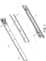
- FIG. 1 to FIG. 3 are diagrams showing a slide rail assembly 30 configured to be mounted to a rack 32.
- the rack 32 comprises a first post 34a and a second post 34b.
- the slide rail assembly 30 is mounted to the first post 34a of the rack 32 through a first bracket 36 and mounted to the second post 34b through a second bracket 38.
- the slide rail assembly 30 comprises a rail member 40 and a supporting device.
- the supporting device comprises a first supporting frame 42 and a second supporting frame 44.
- the first supporting frame 42 is connected (such as fixedly connected) to the rail member 40.
- FIG. 4 is a cross-sectional view of the slide rail assembly 30.
- the first supporting frame 42 has a first supporting means comprising a first supporting part 46 and a second supporting part 48.
- a supporting passage 50 is defined by the first supporting part 46 and the second supporting part 48.
- a first gap G1 is defined between a first supporting position P1 on the first supporting part 46 and a second supporting position P2 on the second supporting part 48
- a second gap G2 is defined between a third supporting position P3 on the first supporting part 46 and a fourth supporting position P4 on the second supporting part 48.
- the second gap G2 is different from the first gap G1.
- the second supporting frame 44 has a second supporting means comprising a third supporting part 52 and a fourth supporting part 54.
- the first supporting part 46 of the first supporting frame 42 is configured to support the third supporting part 52 of the second supporting frame 44
- the second supporting part 48 of the first supporting frame 42 is configured to support the fourth supporting part 54 of the second supporting frame 48.
- the rail member 40 has a first side 56a and a second side 56b.
- the first side 56a of the rail member 40 is formed with a slide rail passage 58.
- the first supporting frame 42 is connected to the second side 56b of the rail member 40.
- the slide rail assembly 30 further comprises a first rail 60 slidable within the slide rail passage 58 of the rail member 40, and a second rail 62 slidably connected to the first rail 60.
- the first supporting frame 42 further comprises a first side wall 64 extendedly connected to the first supporting part 46 and the second supporting part 48.
- the second supporting frame 44 further comprises a second side wall 66 extendedly connected to the third supporting part 52 and the fourth supporting part 54.
- the first side wall 64 of the first supporting frame 42 is configured to support the second side wall 66 of the second supporting frame 44.
- the first supporting part 46 of the first supporting frame 42 has a first portion 68 and a second portion 70.
- the first portion 68 is extended from a first end of the first side wall 64 to form a first angle ⁇ 1 therebetween.
- the second portion 70 is extended from the first portion 68 to form a second angle ⁇ 2 therebetween.
- the second supporting part 48 of the first supporting frame 42 has a third portion 72 and a fourth portion 74.
- the third portion 72 is extended from a second end of the first side wall 64 to form a third angle ⁇ 3 therebetween.
- the fourth portion 74 is extended from the third portion 72 to form a fourth angle ⁇ 4 therebetween.
- the third supporting part 52 of the second supporting frame 44 has a fifth portion 76 and a sixth portion 78.
- the fifth portion 76 is extended from a first end of the second side wall 66 to form a fifth angle ⁇ 5 therebetween.
- the sixth portion 78 is extended from the fifth portion 76 to form a sixth angle ⁇ 6 therebetween.
- the fourth supporting part 54 of the second supporting frame 44 has a seventh portion 80 and an eighth portion 82.
- the seventh portion 80 is extended from a second end of the second side wall 66 to form a seventh angle ⁇ 7 therebetween.
- the eighth portion 82 is extended from the seventh portion 80 to form an eighth angle ⁇ 8 therebetween.
- each of portions of the supporting part 46, 48, 52, 54 is bent a predetermined angle without being folded to lean against an adjacent portion of the same supporting part.
- the third angle ⁇ 3 is substantially equal to the first angle ⁇ 1
- the fourth angle ⁇ 4 is substantially equal to the second angle ⁇ 2
- the seventh angle ⁇ 7 is substantially equal to the fifth angle ⁇ 5
- the eighth angle ⁇ 8 is substantially equal to the sixth angle ⁇ 6.
- Each of the angles ⁇ 1 ⁇ 8 is approximately 90 degrees.
- at least one of the angles ⁇ 1 ⁇ 8 can be arranged as a non-vertical angle, such as an obtuse angle or an acute angle, which is illustrated in the following embodiments.
- FIG. 5 is a diagram showing supporting arrangement between a first supporting frame 200 and a second supporting frame 202 .
- Arrangement of the first supporting frame 200 is identical to arrangement of the first supporting frame 42.
- the first supporting frame 200 has a first supporting means comprising a first supporting part 206, a second supporting part 208 and a first side wall 204 extendedly connected to the first supporting part 206 and the second supporting part 208.
- the second supporting frame 202 has a second supporting means comprising a third supporting part 212, a fourth supporting part 214 and a second side wall 210 extendedly connected to the third supporting part 212 and the fourth supporting part 214.
- the first supporting part 206 of the first supporting frame 200 is configured to support the third supporting part 212 and an upper wall portion of the second side wall 210 of the second supporting frame 202.
- the second supporting part 208 of the first supporting frame 200 is configured to support the fourth supporting part 214 and a lower wall portion of the second side wall 210 of the second supporting frame 202.
- the first side wall 204 of the first supporting frame 200 is configured to support the third supporting part 212 and the fourth supporting part 214 of the second supporting frame 202.
- FIG. 6 is a diagram showing supporting arrangement between a first supporting frame 300 and a second supporting frame 302 .
- the first supporting frame 300 has a first supporting means comprising a first supporting part 306, a second supporting part 310, a first upper wall 304 extendedly connected to the first supporting part 306 and a first lower wall 308 extendedly connected to the second supporting part 310.
- the second supporting frame 302 has a second supporting means comprising a third supporting part 314, a fourth supporting part 316 and a second side wall 312 extendedly connected to the third supporting part 314 and the fourth supporting part 316.
- the first upper wall 304 and the first lower wall 308 of the first supporting frame 300 are configured to support the second side wall 312 of the second supporting frame 302.
- FIG. 7 is a diagram showing supporting arrangement between a first supporting frame 400 and a second supporting frame 402 .
- the first supporting frame 400 has a first supporting means comprising a first supporting part 406, a second supporting part 408 and a first side wall 404 extendedly connected to the first supporting part 406 and the second supporting part 408.
- the second supporting frame 402 has a second supporting means comprising a third supporting part 412, a fourth supporting part 414 and a second side wall 410 extendedly connected to the third supporting part 412 and the fourth supporting part 414.
- the first side wall 404 of the first supporting frame 400 is configured to support the third supporting part 412 and the fourth supporting part 414 of the second supporting frame 402.
- the first supporting part 406 of the first supporting frame 400 is configured to support an upper wall portion of the second side wall 410 of the second supporting frame 402.
- the second supporting part 408 of the first supporting frame 400 is configured to support a lower wall portion of the second side wall 410 of the second supporting frame 402.
- FIG. 8 is a diagram showing supporting arrangement between a first supporting frame 500 and a second supporting frame 502 .
- the first supporting frame 500 has a first supporting means comprising a first supporting part 506, a second supporting part 508 and a first side wall 504 extendedly connected to the first supporting part 506, and the second supporting part 508.
- the second supporting frame 502 has a second supporting means comprising a third supporting part 512, a fourth supporting part 514, and a second side wall 510 extendedly connected to the third supporting part 512 and the fourth supporting part 514.
- the first side wall 504 has a first bending section 516 and a second bending section 518.
- the first bending section 516 of the first supporting frame 500 is configured to support the third supporting part 512 of the second supporting frame 502.
- the second bending section 518 of the first supporting frame 500 is configured to support the fourth supporting part 514 of the second supporting frame 502.
- the first supporting part 506 of the first supporting frame 500 is configured to support the third supporting part 512 and the second side wall 510 of the second supporting frame 502.
- the second supporting part 508 of the first supporting frame 500 is configured to support the fourth supporting part 514 and the second side wall 510 of the second supporting frame 502.
- FIG. 9 is a diagram showing supporting arrangement between a first supporting frame 600 and a second supporting frame 602 .
- the first supporting frame 600 has a first supporting means comprising a first supporting part 606 and a second supporting part 608.
- the second supporting frame 602 has a second supporting means comprising a third supporting part 612, a fourth supporting part 614 and a second side wall 610 extendedly connected to the third supporting part 612 and the fourth supporting part 614.
- the first supporting part 606 of the first supporting frame 600 is configured to support the third supporting part 612 and the second side wall 610 of the second supporting frame 602.
- the second supporting part 608 of the first supporting frame 600 is configured to support the fourth supporting part 614 and the second side wall 610 of the second supporting frame 602.
- the first supporting means further comprises a fifth supporting part 616 and a sixth supporting part 618.
- the fifth supporting part 616 is extended from the first supporting part 606 of the first supporting frame 600 and is located outside a supporting passage 620 of the first supporting frame 600 for supporting the third supporting part 612 of the second supporting frame 602.
- the sixth supporting part 618 is extended from the second supporting part 608 of the first supporting frame 600 and is located outside the supporting passage 620 of the first supporting frame 600 for supporting the fourth supporting part 614 of the second supporting frame 602.
- FIG. 10 is a diagram showing supporting arrangement between a first supporting frame 700 and a second supporting frame 702 .
- the first supporting frame 700 has a first supporting means comprising a first supporting part 706 and a second supporting part 708.
- the second supporting frame 702 has a second supporting means comprising a third supporting part 712, a fourth supporting part 714 and a second side wall 710 extendedly connected to the third supporting part 712 and the fourth supporting part 714.
- the first supporting part 706 of the first supporting frame 700 is configured to support the third supporting part 712 and the second side wall 710 of the second supporting frame 702.
- the second supporting part 708 of the first supporting frame 700 is configured to support the fourth supporting part 714 and the second side wall 710 of the second supporting frame 702.
- the first supporting means further comprises a fifth supporting part 716, a sixth supporting part 718 and a first side wall 704 extendedly connected to the fifth supporting part 716 and the sixth supporting part 718.
- the fifth supporting part 716 is extended from the first supporting part 706 of the first supporting frame 700 and located outside a supporting passage 720 of the first supporting frame 700 for supporting the third supporting part 712 of the second supporting frame 702.
- the sixth supporting part 718 is extended from the second supporting part 708 of the first supporting frame 700 and located outside the supporting passage 720 of the first supporting frame 700 for supporting the fourth supporting part 714 of the second supporting frame 702.
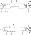
- FIG. 11 is a diagram showing supporting arrangement between a first supporting frame 800 and a second supporting frame 802 .
- the first supporting frame 800 has a first supporting means comprising a first supporting part 806, a second supporting part 808 and a first side wall 804 extendedly connected to the first supporting part 806 and the second supporting part 808.
- the second supporting frame 802 has a second supporting means comprising a third supporting part 812, a fourth supporting part 814 and a second side wall 810 extendedly connected to the third supporting part 812 and the fourth supporting part 814.
- the first side wall 804 has a first bending section 816 and a second bending section 818.
- the first bending section 816 of the first supporting frame 800 is configured to support the third supporting part 812 of the second supporting frame 802.
- the second bending section 818 of the first supporting frame 800 is configured to support the fourth supporting part 814 of the second supporting frame 802.
- the first supporting part 806 of the first supporting frame 800 is configured to support the third supporting part 812 and the second side wall 810 of the second supporting frame 802.
- the second supporting part 808 of the first supporting frame 800 is configured to support the fourth supporting part 814 and the second side wall 810 of the second supporting frame 802.
- FIG. 12 is a diagram showing supporting arrangement between a first supporting frame 900 and a second supporting frame 902.
- the first supporting frame 900 has a first supporting means comprising a first supporting part 906, a second supporting part 908 and a first side wall 904 extendedly connected to the first supporting part 906 and the second supporting part 908.
- the second supporting frame 902 has a second supporting means comprising a third supporting part 912, a fourth supporting part 914 and a second side wall 910 extendedly connected to the third supporting part 912 and the fourth supporting part 914.
- the first supporting part 906 of the first supporting frame 900 is configured to support the third supporting part 912 and an upper wall portion of the second side wall 910 of the second supporting frame 902.
- the second supporting part 908 of the first supporting frame 900 is configured to support the fourth supporting part 914 and a lower wall portion of the second side wall 910 of the second supporting frame 902.
- Each of the third supporting part 912 and the fourth supporting part 914 of the second supporting frame 902 has an end formed with a bending section 916, 918 extended away from the first side wall 904 of the first supporting frame 900.
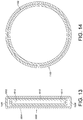
- FIG. 13 is a diagram showing supporting arrangement between a first supporting frame 1000 and a second supporting frame 1002 according to the present invention.
- the first supporting frame 1000 has a first supporting means comprising a first supporting part 1006, a second supporting part 1008 and a first side wall 1004 extendedly connected to two ends of the first supporting part 1006 and two ends of the second supporting part 1008 in order to form a first closed supporting structure (such as a rectangular closed supporting structure).
- the second supporting frame 1002 has a second supporting means comprising a third supporting part 1012, a fourth supporting part 1014 and a second side wall 1010 extendedly connected to two ends of the third supporting part 1012 and two ends of the fourth supporting part 1014 in order to form a second closed supporting structure.
- the first closed supporting structure and the second closed supporting structure are configured to support each other.
- FIG. 14 is a diagram showing supporting arrangement between a first supporting frame 1100 and a second supporting frame 1102 not according to the invention. Arrangement of the present embodiment is similar to that of the embodiment shown in FIG. 13 .
- the first supporting frame 1100 forms a first closed supporting structure (such as a circular closed supporting structure) .
- the second supporting frame 1102 forms a second closed supporting structure.
- the first closed supporting structure and the second closed supporting structure supports each other.
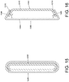
- FIG. 15 is a diagram showing supporting arrangement between a first supporting frame 1200 and a second supporting frame 1202 according to the present invention. Arrangement of the present embodiment is similar to that of the embodiment shown in FIG. 13 .
- the first supporting frame 1200 forms a first closed supporting structure (such as a closed supporting structure having curved contours at two corresponding ends).
- the second supporting frame 1202 forms a second closed supporting structure. The first closed supporting structure and the second closed supporting structure support each other.
- FIG. 16 is a diagram showing supporting arrangement between a first supporting frame 1300 and a second supporting frame 1302 .
- the first supporting frame 1300 has a first supporting means comprising a first supporting part 1306, a second supporting part 1308 and a first side wall 1304 extendedly connected to the first supporting part 1306 and the second supporting part 1308.
- the second supporting frame 1302 has a second supporting means comprising a third supporting part 1312, a fourth supporting part 1314 and a second side wall 1310 extendedly connected to the third supporting part 1312 and the fourth supporting part 1314.
- the first supporting part 1306 of the first supporting frame 1300 is configured to support the third supporting part 1312 of the second supporting frame 1302.
- the second supporting part 1308 of the first supporting frame 1300 is configured to support the fourth supporting part 1314 of the second supporting frame 1302.
- the first supporting part 1306 is extended from a first end of the first side wall 1304 to form a first angle ⁇ 1 therebetween.
- the second supporting part 1308 is extended from a second end of the first side wall 1304 to form a second angle ⁇ 2 therebetween.
- the first angle ⁇ 1 is substantially equal to the second angle ⁇ 2 and arranged as an acute angle.
- the first side wall 1304 of the first supporting frame 1300 and the second side wall 1310 of the second supporting frame 1302 do not directly contact and support each other.
- FIG. 17 is a diagram showing supporting arrangement between a first supporting frame 1400 and a second supporting frame 1402.
- the first supporting frame 1400 has a first supporting means comprising a first supporting part 1406, a second supporting part 1408 and a first side wall 1404 extendedly connected to the first supporting part 1406 and the second supporting part 1408.
- the second supporting frame 1402 has a second supporting means comprising a third supporting part 1412, a fourth supporting part 1414 and a second side wall 1410 extendedly connected to the third supporting part 1412 and the fourth supporting part 1414.
- the first supporting part 1406 of the first supporting frame 1400 is configured to support the third supporting part 1412 of the second supporting frame 1402.
- the second supporting part 1408 of the first supporting frame 1400 is configured to support the fourth supporting part 1414 of the second supporting frame 1402.
- the first side wall 1404 of the first supporting frame 1400 is configured to support the second side wall 1410 of the second supporting frame 1402.
- FIG. 18 is a diagram showing supporting arrangement between a first supporting frame 1500 and a second supporting frame 1502 .
- the first supporting frame 1500 has a first supporting means comprising a first supporting part 1506, a second supporting part 1508 and a first side wall 1504 extendedly connected to the first supporting part 1506 and the second supporting part 1508.
- the second supporting frame 1502 has a second supporting means comprising a third supporting part 1512, a fourth supporting part 1514 and a second side wall 1510 extendedly connected to the third supporting part 1512 and the fourth supporting part 1514.
- the first supporting part 1506 of the first supporting frame 1500 is configured to support the third supporting part 1512 of the second supporting frame 1502.
- the second supporting part 1508 of the first supporting frame 1500 is configured to support the fourth supporting part 1514 of the second supporting frame 1502.
- first side wall 1504 of the first supporting frame 1500 is configured to support the second side wall 1510 of the second supporting frame 1502.
- the first supporting part 1506 of the first supporting frame 1500 has a first portion 1516 and a second portion 1518.
- the first portion 1516 is extended from a first end of the first side wall 1504 to form a first angle ⁇ 1 therebetween.
- the second portion 1518 is extended from the first portion 1516 to form a second angle ⁇ 2 therebetween.
- the second supporting part 1508 of the first supporting frame 1500 has a third portion 1520 and a fourth portion 1522.
- the third portion 1520 is extended from a second end of the first side wall 1504 to form a third angle ⁇ 3 therebetween.
- the fourth portion 1522 is extended from the third portion 1520 to form a fourth angle ⁇ 4 therebetween.
- the third supporting part 1512 of the second supporting frame 1502 has a fifth portion 1524 and a sixth portion 1526.
- the fifth portion 1524 is extended from a first end of the second side wall 1510 to form a fifth angle ⁇ 5 therebetween.
- the sixth portion 1526 is extended from the fifth portion 1524 to form a sixth angle ⁇ 6 therebetween.
- the fourth supporting part 1514 of the second supporting frame 1502 has a seventh portion 1528 and an eighth portion 1530.
- the seventh portion 1528 is extended from a second end of the second side wall 1510 to form a seventh angle ⁇ 7 therebetween.
- the eighth portion 1530 is extended from the seventh portion 1528 to form an eighth angle ⁇ 8 therebetween.
- the third angle ⁇ 3 is substantially equal to the first angle ⁇ 1
- the seventh angle ⁇ 7 is substantially equal to the fifth angle ⁇ 5.
- Each of the first, the third, the fifth, and the seventh angles ⁇ 1, ⁇ 3, ⁇ 5, ⁇ 7 is arranged as an acute angle.
- the fourth angle ⁇ 4 is substantially equal to the second angle ⁇ 2.
- the eighth angle ⁇ 8 is substantially equal to the sixth angle ⁇ 6.
- Each of the second, the fourth, the sixth, and the eighth angles ⁇ 2, ⁇ 4, ⁇ 6, ⁇ 8 is approximately 90 degrees.
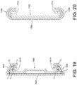
- FIG. 19 is a diagram showing supporting arrangement between a first supporting frame 1600 and a second supporting frame 1602 .
- Arrangement of the present embodiment is similar to that of the fifteenth embodiment shown in FIG. 18 .
- Bending angles of a first supporting part 1606 and a second supporting part 1608 of the first supporting frame 1600 and bending angles of a third supporting part 1612 and a fourth supporting part 1614 of the second supporting frame 1602 of the present embodiment are different from those of the fifteenth embodiment.
- each of the second, the fourth, the sixth, and the eighth angles ⁇ 2, ⁇ 4, ⁇ 6, ⁇ 8 is arranged as an obtuse angle.
- FIG. 20 is a diagram showing supporting arrangement between a first supporting frame 1700 and a second supporting frame 1702 .
- Arrangement of the present embodiment is similar to that of the fifteenth embodiment shown in FIG. 18 .
- a main difference between the two embodiments is that a first supporting part 1706 and a second supporting part 1708 of the first supporting frame 1700 have curved supporting contours respectively corresponding to and contacting with curved supporting contours of a third supporting part 1712 and a fourth supporting part 1714 of the second supporting frame 1702.
- FIG. 21 is a diagram showing supporting arrangement between a first supporting frame 1800 and a second supporting frame 1802 Arrangement of the present embodiment is similar to that of the seventeenth embodiment shown in FIG. 20 .
- a main difference between the two embodiments is that a first supporting part 1806 and a second supporting part 1808 of the first supporting frame 1800 have another curved supporting contours respectively corresponding to and contacting with another curved supporting contours of a third supporting part 1812 and a fourth supporting part 1814 of the second supporting frame 1802, such that shapes of the first supporting frame 1800 and the second supporting frame 1802 of the present embodiment are different from those of fig. 20 .
- FIG. 22 is a diagram showing supporting arrangement between a first supporting frame 1900 and a second supporting frame 1902 .
- the first supporting frame 1900 has a first supporting means comprising a first supporting part 1906 and a second supporting part 1908.
- the first supporting part 1906 has a first turning section 1916 and a second turning section 1918.
- the first turning section 1916 is extended from a first end of a first side wall 1904 to form a first angle ⁇ 1 therebetween.
- the second turning section 1918 is extended from the first turning section 1916 to form a second angle ⁇ 2 therebetween.
- the first angle ⁇ 1 is arranged as an acute angle and the second angle ⁇ 2 is arranged as an obtuse angle.
- the second supporting frame 1902 has a second supporting means comprising a third supporting part 1912 and a fourth supporting part 1914.
- the third supporting part 1912 has a third turning section 1920 and a fourth turning section 1922.
- the third turning section 1920 is extended from a first end of a second side wall 1910 to form a third angle ⁇ 3 therebetween.
- the fourth turning section 1922 is extended from the third turning section 1920 to form a fourth angle ⁇ 4 therebetween.
- the third angle ⁇ 3 is arranged as an acute angle and the fourth angle ⁇ 4 is arranged as an obtuse angle.
- Supporting arrangement of the other sides (the second supporting part 1908 and the fourth supporting part 1914) of the first supporting frame 1900 and the second supporting frame 1902 is symmetric to the above arrangement. Therefore, no further illustration is provided.
- FIG. 23 is a diagram showing supporting arrangement between a first supporting frame 2000 and a second supporting frame 2002 .
- the first supporting frame 2000 has a first supporting means comprising a first supporting part 2006 and a second supporting part 2008.
- the second supporting frame 2002 has a second supporting means comprising a third supporting part 2012 and a fourth supporting part 2014.
- the first supporting means of the first supporting frame 2000 have a roll-shaped supporting contour corresponding to and contacting with a roll-shaped supporting contour of the second supporting means of the second supporting frame 2002.
- FIG. 24 is a diagram showing supporting arrangement between a first supporting frame 2100 and a second supporting frame 2102
- a first supporting part 2106 and a second supporting part 2108 of the first supporting frame 2100 have roll-shaped supporting contours respectively corresponding to and contacting with roll-shaped supporting contours of a third supporting part 2112 and a fourth supporting part 2114 of the second supporting frame 2108.
- a main difference is that a first side wall 2104 of the first supporting frame 2100 and a second side wall 2110 of the second supporting frame 2102 have portions not configured to support each other.
- FIG. 25 is a diagram showing supporting arrangement between a first supporting frame 2200 and a second supporting frame 2202 according to a twenty second embodiment of the present invention.
- the first supporting frame 2200 has a first supporting means comprising a first supporting part 2206, a second supporting part 2208 and a first side wall 2204 extendedly connected to the first supporting part 2206 and the second supporting part 2208.
- the second supporting frame 2202 has a second supporting means comprising a third supporting part 2212, a fourth supporting part 2214 and a second side wall 2210 extendedly connected to the third supporting part 2212 and the fourth supporting part 2214.
- the first supporting part 2206 of the first supporting frame 2200 is configured to support the third supporting part 2212 of the second supporting frame 2202.
- the second supporting part 2208 of the first supporting frame 2200 is configured to support the fourth supporting part 2214 of the second supporting frame 2202.
- the third supporting part 2212 and the fourth supporting part 2214 of the second supporting frame 2202 are located outside a supporting passage 2216 of the first supporting frame 2200.
- the third supporting part 2212 of the second supporting frame 2202 and the first supporting part 2206 of the first supporting frame 2200 are configured to support each other; and the fourth supporting part 2214 of the second supporting frame 2202 and the second supporting part 2208 of the first supporting frame 2200 are configured to support each other.
- FIG. 26 is a diagram showing supporting arrangement between a first supporting frame 2300 and a second supporting frame 2302 .
- the first supporting frame 2300 has a first supporting means comprising a first supporting part 2306, a second supporting part 2308 and a first side wall 2304 extendedly connected to the first supporting part 2306 and the second supporting part 2308.
- the second supporting frame 2302 has a second supporting means comprising a third supporting part 2312, a fourth supporting part 2314 and a second side wall 2310 extendedly connected to the third supporting part 2312 and the fourth supporting part 2314.
- the first supporting part 2306 of the first supporting frame 2300 is configured to support the third supporting part 2312 of the second supporting frame 2302.
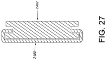
- FIG. 27 is a diagram showing supporting arrangement between a first supporting frame 2400 and a second supporting frame 2402. Arrangement of the present embodiment is similar to that of Fig. 23 . A main difference between the two embodiments is that mounting positions of the two frames are different.
Landscapes
- Engineering & Computer Science (AREA)
- General Engineering & Computer Science (AREA)
- Computer Hardware Design (AREA)
- Microelectronics & Electronic Packaging (AREA)
- Mechanical Engineering (AREA)
- Drawers Of Furniture (AREA)
- Tables And Desks Characterized By Structural Shape (AREA)
- Bearings For Parts Moving Linearly (AREA)
Claims (2)
- Gleitschienenaufbau (30), welcher ausgestaltet ist, an einem Gestell (32) befestigt zu werden, worin das Gestell (32) eine erste Säule (34a) und eine zweite Säule (34b) umfasst, worin der Gleitschienenaufbau (30) ausgestaltet ist, an der ersten Säule (34a) des Gestells (32) durch ein erste Halterung (36) befestigt zu werden und an der zweiten Säule (34b) durch eine zweite Halterung (38) befestigt zu werden, worin der Gleitschienenaufbau (30) ein Schienenelement (40) und eine Stützeinrichtung umfasst,
worin die Stützeinrichtung für das Schienenelement (40) ausgestaltet ist, und umfasst:einen ersten Halterahmen (1000, 1200) mit einem ersten Stützmittel, das ein erstes Stützteil (1006) und ein zweites Stützteil (1008) umfasst, worin ein Stützpassage durch das erste Stützteil (1006) und das zweite Stützteil (1008) definiert wird; undeinen zweiten Halterahmen (1002, 1202) mit einem zweiten Stützmittel, das ein drittes Stützteil (1012) und ein viertes Stützteil 1014) umfasst, worin sich das erste Stützmittel und das zweite Stützmittel gegenseitig stützen;worin das Schienenelement (40) mit dem ersten Halterahmen (1000, 1200) fest verbunden ist, das erste Stützteil (1006) des ersten Halterahmens (1000, 1200) das dritte Stützteil (1012) des zweiten Halterahmens (1002, 1202) stützt, und das zweite Stützteil (1008) des ersten Halterahmens (1000, 1200) das vierte Stützteil (1014) des zweiten Halterahmens (1002, 1202) stützt;dadurch gekennzeichnet, dass der erste Halterahmen (1000, 1200) weiter eine erste Seitenwand (1004) umfasst, die mit zwei Enden des ersten Stützteils (1006) und zwei Enden des zweiten Stützteils (1008) erstreckend verbunden ist, um eine erste geschlossene Stützstruktur auszubilden, der zweite Halterahmen (1002, 1202) weiter eine zweite Seitenwand (1010) umfasst, die mit zwei Enden des dritten Stützteils (1012) und zwei Enden des vierten Stützteils (1014) ersteckend verbunden ist, um eine zweite geschlossene Stützstruktur auszubilden, und sich die erste geschlossene Stützstruktur und die zweite geschlossene Stützstruktur gegenseitig stützen;worin das Schienenelement (40) aufweist, eine erste Seite (56a) und eine zweite Seite (56b), worin die erste Seite (56a) des Schienenelementes (40) mit einer Gleitschienenpassage (58) ausgebildet ist, der erste Halterahmen (1000, 1200) mit der zweiten Seite (56b) des Schienenelementes (40) verbunden ist, und die Gleitschienenpassage (58) des Schienenelementes (40) eine erste Schiene (60) aufnimmt, damit die erste Schiene (60) in der Gleitschienenpassage (58) des Schienenelementes (40) gleiten kann, und eine zweite Schiene (62) mit der ersten Schiene (60) gleitend verbunden ist. - Gleitschienenaufbau (30) nach Anspruch 1, dadurch gekennzeichnet, dass die erste Seitenwand (1004) des ersten Halterahmens (1000, 1200) ausgestaltet ist, die zweite Seitenwand (1010) des zweiten Halterahmens (1002, 1202) zu stützen.
Priority Applications (1)
| Application Number | Priority Date | Filing Date | Title |
|---|---|---|---|
| EP21150529.2A EP3824761B1 (de) | 2016-06-16 | 2016-10-25 | Unterstützungsvorrichtung für schienenelement |
Applications Claiming Priority (1)
| Application Number | Priority Date | Filing Date | Title |
|---|---|---|---|
| TW105119025A TWI594712B (zh) | 2016-06-16 | 2016-06-16 | 軌件的支撐裝置 |
Related Child Applications (1)
| Application Number | Title | Priority Date | Filing Date |
|---|---|---|---|
| EP21150529.2A Division EP3824761B1 (de) | 2016-06-16 | 2016-10-25 | Unterstützungsvorrichtung für schienenelement |
Publications (2)
| Publication Number | Publication Date |
|---|---|
| EP3258753A1 EP3258753A1 (de) | 2017-12-20 |
| EP3258753B1 true EP3258753B1 (de) | 2021-01-27 |
Family
ID=57288140
Family Applications (2)
| Application Number | Title | Priority Date | Filing Date |
|---|---|---|---|
| EP21150529.2A Active EP3824761B1 (de) | 2016-06-16 | 2016-10-25 | Unterstützungsvorrichtung für schienenelement |
| EP16195412.8A Active EP3258753B1 (de) | 2016-06-16 | 2016-10-25 | Unterstützungsvorrichtung für schienenelement |
Family Applications Before (1)
| Application Number | Title | Priority Date | Filing Date |
|---|---|---|---|
| EP21150529.2A Active EP3824761B1 (de) | 2016-06-16 | 2016-10-25 | Unterstützungsvorrichtung für schienenelement |
Country Status (4)
| Country | Link |
|---|---|
| US (5) | US20170363144A1 (de) |
| EP (2) | EP3824761B1 (de) |
| JP (1) | JP6368752B2 (de) |
| TW (1) | TWI594712B (de) |
Families Citing this family (11)
| Publication number | Priority date | Publication date | Assignee | Title |
|---|---|---|---|---|
| JP6724338B2 (ja) | 2015-10-30 | 2020-07-15 | ブラザー工業株式会社 | 通信機器 |
| TWI600393B (zh) * | 2016-11-22 | 2017-10-01 | 川湖科技股份有限公司 | 軌件的支撐裝置 |
| USD871812S1 (en) * | 2017-03-31 | 2020-01-07 | King Slide Works Co., Ltd. | Drawer side panel |
| US10356931B1 (en) * | 2017-05-26 | 2019-07-16 | King Slide Works Co., Ltd. | Rack mounting system |
| US11547012B2 (en) * | 2019-04-24 | 2023-01-03 | Hewlett Packard Enterprise Development Lp | Rail kit strengthening bracket |
| TWI704891B (zh) * | 2019-07-29 | 2020-09-21 | 川湖科技股份有限公司 | 滑軌機構 |
| TWI715287B (zh) * | 2019-11-13 | 2021-01-01 | 新加坡商鴻運科股份有限公司 | 滑軌組件 |
| US11864652B1 (en) * | 2022-06-29 | 2024-01-09 | Martas Precision Slide Co., Ltd. | Geometric reinforcing structure for slide rail |
| TWI818879B (zh) * | 2023-03-27 | 2023-10-11 | 川湖科技股份有限公司 | 滑軌總成及其滑軌 |
| USD1071699S1 (en) * | 2023-07-14 | 2025-04-22 | Accuride International Gmbh | Slide rail |
| US20250344911A1 (en) * | 2024-05-10 | 2025-11-13 | Raul B. Cabada | Adjustable Tissue Dispenser and Method for Using the Same |
Citations (1)
| Publication number | Priority date | Publication date | Assignee | Title |
|---|---|---|---|---|
| EP1540253A1 (de) * | 2002-09-09 | 2005-06-15 | BSH Bosch und Siemens Hausgeräte GmbH | Schienen- und teleskopauszug |
Family Cites Families (39)
| Publication number | Priority date | Publication date | Assignee | Title |
|---|---|---|---|---|
| DE159675C (de) * | ||||
| GB105990A (en) | 1916-05-09 | 1917-05-09 | Alfred Leslie Hookham | Improvements in Filing Cabinets and like Articles of Furniture. |
| US1231291A (en) | 1916-09-21 | 1917-06-26 | Otho M Otte | Flour-bin for kitchen-cabinets. |
| US1301495A (en) | 1919-03-15 | 1919-04-22 | Steelwhite Company | Suspension for drawers and similar receptacles. |
| AT159675B (de) | 1938-05-14 | 1940-10-25 | Mannesmann Stahlblechbau Ag | Metallschrank mit ausziehbaren Kästen. |
| US2277703A (en) | 1941-05-02 | 1942-03-31 | Kennedy Mfg Company | Drawer slide |
| US2698214A (en) * | 1951-02-16 | 1954-12-28 | Clarence M Skamser | Adjustable drawer slide |
| US3033638A (en) * | 1959-05-13 | 1962-05-08 | John K Tomlinson | Slide suspension |
| US3059986A (en) | 1961-06-19 | 1962-10-23 | Space Tone Electronics Corp | Full extension drawer slide assembly |
| US3289044A (en) * | 1965-04-21 | 1966-11-29 | American Radiator & Standard | Slidable terminal contactor |
| US4047767A (en) | 1976-03-15 | 1977-09-13 | Foust Robert K | Slide assembly |
| US4440461A (en) * | 1981-04-06 | 1984-04-03 | Sinclair & Powell Proprietary Limited | Slide arrangement |
| JPS62262847A (ja) * | 1986-05-09 | 1987-11-14 | Canon Inc | 移動式原稿載置台を伴う原稿読取り装置 |
| JPH01188870A (ja) * | 1988-01-25 | 1989-07-28 | Canon Inc | スライドレール |
| AT390552B (de) | 1988-09-15 | 1990-05-25 | Blum Gmbh Julius | Fuehrungsschienengarnitur fuer schubladen |
| US4944605A (en) | 1989-10-02 | 1990-07-31 | Shen Ming T | Drawer slides sets |
| US5634701A (en) | 1994-08-31 | 1997-06-03 | Fireking International, Inc. | Multi-drawer cabinet having a drawer lock-out mechanism |
| US5624171A (en) | 1995-07-24 | 1997-04-29 | Durham Manufacturing Company | Two-track drawer slide having function of three-track slide |
| JP3152281B2 (ja) * | 1996-06-27 | 2001-04-03 | 富士ゼロックス株式会社 | ネットワーク環境におけるプリント・システム |
| US6681942B2 (en) | 1999-10-27 | 2004-01-27 | Hewlett-Packard Development Company | Rack mount assembly |
| JP4874506B2 (ja) * | 2000-11-16 | 2012-02-15 | アキュライド インターナショナル,インコーポレイテッド | 摩擦引出しスライド |
| DE10206075A1 (de) | 2002-02-13 | 2003-11-13 | Westfalia Profiltechnik Gmbh & | Verstell- bzw. Schienensystem von Fahrzeugsitzen, Schubladen, Auszügen für Werkstattwagen oder dergleichen |
| US6834923B2 (en) | 2003-02-10 | 2004-12-28 | Jonathan Manufacturing Corporation | Miniature solid bearing slide assembly |
| JP4416597B2 (ja) * | 2004-07-30 | 2010-02-17 | グローブライド株式会社 | 伸縮装置 |
| US20060152115A1 (en) * | 2005-01-07 | 2006-07-13 | William Dubon | Adjustable reinforcing bracket for telescoping slide rail assembly |
| DE102005021591A1 (de) | 2005-05-10 | 2006-11-16 | BSH Bosch und Siemens Hausgeräte GmbH | Haushaltsgerät mit Teleskopauszug |
| US20080036347A1 (en) * | 2006-08-09 | 2008-02-14 | Super Micro Computer, Inc. | Rail device for extracting computer equipment |
| TWI339109B (en) * | 2006-12-15 | 2011-03-21 | Hon Hai Prec Ind Co Ltd | Slide assembly |
| TWI361651B (en) * | 2008-05-16 | 2012-04-01 | King Slide Works Co Ltd | Bracket for a slide assembly |
| TW201018369A (en) * | 2008-10-16 | 2010-05-01 | Ablecom Technology Inc | Ultra-thin fast assembling/ disassembling slide track |
| JP5146345B2 (ja) * | 2009-02-09 | 2013-02-20 | 富士通モバイルコミュニケーションズ株式会社 | 電子機器 |
| JP2011106660A (ja) * | 2009-11-16 | 2011-06-02 | Hiroshi Araihara | スライドレール |
| CN102100452B (zh) * | 2009-12-16 | 2014-04-23 | 鸿富锦精密工业(深圳)有限公司 | 无滚珠滑轨 |
| CN102210517A (zh) | 2010-04-06 | 2011-10-12 | 鸿富锦精密工业(深圳)有限公司 | 滑轨安装机构及利用该安装机构的滑轨组合 |
| JP5136598B2 (ja) * | 2010-06-10 | 2013-02-06 | コニカミノルタビジネステクノロジーズ株式会社 | スライドレールおよびそれを有する画像形成装置 |
| US9313914B2 (en) | 2013-03-13 | 2016-04-12 | Jonathan Manufacturing Corporation | Slide assembly |
| US9125489B2 (en) | 2013-06-11 | 2015-09-08 | King Slide Works Co., Ltd. | Fixing device for a slide assembly |
| US9328769B1 (en) * | 2015-01-27 | 2016-05-03 | King Slide Works Co., Ltd. | Slide rail assembly and bracket device thereof |
| TWI607722B (zh) | 2015-05-15 | 2017-12-11 | 川湖科技股份有限公司 | 滑軌總成 |
-
2016
- 2016-06-16 TW TW105119025A patent/TWI594712B/zh active
- 2016-09-14 US US15/264,617 patent/US20170363144A1/en not_active Abandoned
- 2016-10-05 JP JP2016197046A patent/JP6368752B2/ja active Active
- 2016-10-25 EP EP21150529.2A patent/EP3824761B1/de active Active
- 2016-10-25 EP EP16195412.8A patent/EP3258753B1/de active Active
-
2018
- 2018-09-13 US US16/130,982 patent/US10578154B2/en active Active
- 2018-09-13 US US16/131,006 patent/US10590987B2/en active Active
- 2018-09-14 US US16/131,038 patent/US10578155B2/en active Active
-
2019
- 2019-10-22 US US16/660,769 patent/US10641328B2/en active Active
Patent Citations (1)
| Publication number | Priority date | Publication date | Assignee | Title |
|---|---|---|---|---|
| EP1540253A1 (de) * | 2002-09-09 | 2005-06-15 | BSH Bosch und Siemens Hausgeräte GmbH | Schienen- und teleskopauszug |
Also Published As
| Publication number | Publication date |
|---|---|
| TWI594712B (zh) | 2017-08-11 |
| EP3824761B1 (de) | 2024-07-24 |
| US20170363144A1 (en) | 2017-12-21 |
| US20200049195A1 (en) | 2020-02-13 |
| US20190010981A1 (en) | 2019-01-10 |
| US10590987B2 (en) | 2020-03-17 |
| US10578155B2 (en) | 2020-03-03 |
| US10641328B2 (en) | 2020-05-05 |
| EP3258753A1 (de) | 2017-12-20 |
| US20190010979A1 (en) | 2019-01-10 |
| EP3824761A1 (de) | 2021-05-26 |
| JP2017223349A (ja) | 2017-12-21 |
| US10578154B2 (en) | 2020-03-03 |
| TW201800036A (zh) | 2018-01-01 |
| US20190010980A1 (en) | 2019-01-10 |
| JP6368752B2 (ja) | 2018-08-01 |
Similar Documents
| Publication | Publication Date | Title |
|---|---|---|
| EP3258753B1 (de) | Unterstützungsvorrichtung für schienenelement | |
| EP3154320B1 (de) | Gleitschienenanordnung und haltevorrichtung dafür | |
| US11116316B2 (en) | Supporting device for rail member | |
| EP3157314B1 (de) | Gleitschienenanordnung für regalsystem | |
| US9073580B2 (en) | Transverse strut | |
| KR20160112208A (ko) | 플렉시블 서포트 | |
| US8601647B2 (en) | Clip | |
| JPWO2008038472A1 (ja) | スライドレールユニット | |
| KR101703234B1 (ko) | 플렉시블 서포트 | |
| JP5316464B2 (ja) | 設置機構 | |
| JP6715535B2 (ja) | 連結構造 | |
| US10729032B1 (en) | Slide rail assembly | |
| JP7321525B2 (ja) | スライドレールユニット | |
| JP6138578B2 (ja) | 棒状アンテナ取付金具 | |
| CN103781592B (zh) | 伸缩波纹管 | |
| US9066440B2 (en) | Side bracket | |
| JP5696099B2 (ja) | 棒状アンテナ取付金具、その金具を使用した径の異なる棒状アンテナの取付方法 | |
| EP3876325B1 (de) | Vorrichtung zum falten von beuteln für sekundärbatterie | |
| CN107529310B (zh) | 轨件的支撑装置 | |
| KR20180044566A (ko) | 겹판스프링의 구조 | |
| CN113775901A (zh) | 悬吊式固定座及其支架单元 | |
| JP3157505U (ja) | ガイドレール | |
| US20150107386A1 (en) | Flexure | |
| JP2012001297A (ja) | ガイド装置 | |
| JP2014511008A (ja) | スクリーニング端子用支持スタンド |
Legal Events
| Date | Code | Title | Description |
|---|---|---|---|
| PUAI | Public reference made under article 153(3) epc to a published international application that has entered the european phase |
Free format text: ORIGINAL CODE: 0009012 |
|
| STAA | Information on the status of an ep patent application or granted ep patent |
Free format text: STATUS: THE APPLICATION HAS BEEN PUBLISHED |
|
| AK | Designated contracting states |
Kind code of ref document: A1 Designated state(s): AL AT BE BG CH CY CZ DE DK EE ES FI FR GB GR HR HU IE IS IT LI LT LU LV MC MK MT NL NO PL PT RO RS SE SI SK SM TR |
|
| AX | Request for extension of the european patent |
Extension state: BA ME |
|
| STAA | Information on the status of an ep patent application or granted ep patent |
Free format text: STATUS: REQUEST FOR EXAMINATION WAS MADE |
|
| 17P | Request for examination filed |
Effective date: 20180612 |
|
| RBV | Designated contracting states (corrected) |
Designated state(s): AL AT BE BG CH CY CZ DE DK EE ES FI FR GB GR HR HU IE IS IT LI LT LU LV MC MK MT NL NO PL PT RO RS SE SI SK SM TR |
|
| STAA | Information on the status of an ep patent application or granted ep patent |
Free format text: STATUS: EXAMINATION IS IN PROGRESS |
|
| 17Q | First examination report despatched |
Effective date: 20181018 |
|
| REG | Reference to a national code |
Ref country code: DE Ref legal event code: R079 Ref document number: 602016051991 Country of ref document: DE Free format text: PREVIOUS MAIN CLASS: H05K0007140000 Ipc: A47B0088400000 |
|
| RIC1 | Information provided on ipc code assigned before grant |
Ipc: A47B 88/40 20170101AFI20191004BHEP Ipc: H05K 7/14 20060101ALI20191004BHEP |
|
| GRAP | Despatch of communication of intention to grant a patent |
Free format text: ORIGINAL CODE: EPIDOSNIGR1 |
|
| STAA | Information on the status of an ep patent application or granted ep patent |
Free format text: STATUS: GRANT OF PATENT IS INTENDED |
|
| INTG | Intention to grant announced |
Effective date: 20200907 |
|
| GRAS | Grant fee paid |
Free format text: ORIGINAL CODE: EPIDOSNIGR3 |
|
| GRAA | (expected) grant |
Free format text: ORIGINAL CODE: 0009210 |
|
| STAA | Information on the status of an ep patent application or granted ep patent |
Free format text: STATUS: THE PATENT HAS BEEN GRANTED |
|
| AK | Designated contracting states |
Kind code of ref document: B1 Designated state(s): AL AT BE BG CH CY CZ DE DK EE ES FI FR GB GR HR HU IE IS IT LI LT LU LV MC MK MT NL NO PL PT RO RS SE SI SK SM TR |
|
| REG | Reference to a national code |
Ref country code: GB Ref legal event code: FG4D |
|
| REG | Reference to a national code |
Ref country code: CH Ref legal event code: EP |
|
| REG | Reference to a national code |
Ref country code: AT Ref legal event code: REF Ref document number: 1357574 Country of ref document: AT Kind code of ref document: T Effective date: 20210215 |
|
| REG | Reference to a national code |
Ref country code: IE Ref legal event code: FG4D |
|
| REG | Reference to a national code |
Ref country code: DE Ref legal event code: R096 Ref document number: 602016051991 Country of ref document: DE |
|
| REG | Reference to a national code |
Ref country code: NL Ref legal event code: MP Effective date: 20210127 |
|
| REG | Reference to a national code |
Ref country code: LT Ref legal event code: MG9D |
|
| REG | Reference to a national code |
Ref country code: AT Ref legal event code: MK05 Ref document number: 1357574 Country of ref document: AT Kind code of ref document: T Effective date: 20210127 |
|
| PG25 | Lapsed in a contracting state [announced via postgrant information from national office to epo] |
Ref country code: BG Free format text: LAPSE BECAUSE OF FAILURE TO SUBMIT A TRANSLATION OF THE DESCRIPTION OR TO PAY THE FEE WITHIN THE PRESCRIBED TIME-LIMIT Effective date: 20210427 Ref country code: LT Free format text: LAPSE BECAUSE OF FAILURE TO SUBMIT A TRANSLATION OF THE DESCRIPTION OR TO PAY THE FEE WITHIN THE PRESCRIBED TIME-LIMIT Effective date: 20210127 Ref country code: GR Free format text: LAPSE BECAUSE OF FAILURE TO SUBMIT A TRANSLATION OF THE DESCRIPTION OR TO PAY THE FEE WITHIN THE PRESCRIBED TIME-LIMIT Effective date: 20210428 Ref country code: HR Free format text: LAPSE BECAUSE OF FAILURE TO SUBMIT A TRANSLATION OF THE DESCRIPTION OR TO PAY THE FEE WITHIN THE PRESCRIBED TIME-LIMIT Effective date: 20210127 Ref country code: FI Free format text: LAPSE BECAUSE OF FAILURE TO SUBMIT A TRANSLATION OF THE DESCRIPTION OR TO PAY THE FEE WITHIN THE PRESCRIBED TIME-LIMIT Effective date: 20210127 Ref country code: NO Free format text: LAPSE BECAUSE OF FAILURE TO SUBMIT A TRANSLATION OF THE DESCRIPTION OR TO PAY THE FEE WITHIN THE PRESCRIBED TIME-LIMIT Effective date: 20210427 Ref country code: PT Free format text: LAPSE BECAUSE OF FAILURE TO SUBMIT A TRANSLATION OF THE DESCRIPTION OR TO PAY THE FEE WITHIN THE PRESCRIBED TIME-LIMIT Effective date: 20210527 |
|
| PG25 | Lapsed in a contracting state [announced via postgrant information from national office to epo] |
Ref country code: SE Free format text: LAPSE BECAUSE OF FAILURE TO SUBMIT A TRANSLATION OF THE DESCRIPTION OR TO PAY THE FEE WITHIN THE PRESCRIBED TIME-LIMIT Effective date: 20210127 Ref country code: LV Free format text: LAPSE BECAUSE OF FAILURE TO SUBMIT A TRANSLATION OF THE DESCRIPTION OR TO PAY THE FEE WITHIN THE PRESCRIBED TIME-LIMIT Effective date: 20210127 Ref country code: PL Free format text: LAPSE BECAUSE OF FAILURE TO SUBMIT A TRANSLATION OF THE DESCRIPTION OR TO PAY THE FEE WITHIN THE PRESCRIBED TIME-LIMIT Effective date: 20210127 Ref country code: RS Free format text: LAPSE BECAUSE OF FAILURE TO SUBMIT A TRANSLATION OF THE DESCRIPTION OR TO PAY THE FEE WITHIN THE PRESCRIBED TIME-LIMIT Effective date: 20210127 Ref country code: AT Free format text: LAPSE BECAUSE OF FAILURE TO SUBMIT A TRANSLATION OF THE DESCRIPTION OR TO PAY THE FEE WITHIN THE PRESCRIBED TIME-LIMIT Effective date: 20210127 |
|
| PG25 | Lapsed in a contracting state [announced via postgrant information from national office to epo] |
Ref country code: IS Free format text: LAPSE BECAUSE OF FAILURE TO SUBMIT A TRANSLATION OF THE DESCRIPTION OR TO PAY THE FEE WITHIN THE PRESCRIBED TIME-LIMIT Effective date: 20210527 |
|
| REG | Reference to a national code |
Ref country code: DE Ref legal event code: R097 Ref document number: 602016051991 Country of ref document: DE |
|
| PG25 | Lapsed in a contracting state [announced via postgrant information from national office to epo] |
Ref country code: CZ Free format text: LAPSE BECAUSE OF FAILURE TO SUBMIT A TRANSLATION OF THE DESCRIPTION OR TO PAY THE FEE WITHIN THE PRESCRIBED TIME-LIMIT Effective date: 20210127 Ref country code: EE Free format text: LAPSE BECAUSE OF FAILURE TO SUBMIT A TRANSLATION OF THE DESCRIPTION OR TO PAY THE FEE WITHIN THE PRESCRIBED TIME-LIMIT Effective date: 20210127 Ref country code: SM Free format text: LAPSE BECAUSE OF FAILURE TO SUBMIT A TRANSLATION OF THE DESCRIPTION OR TO PAY THE FEE WITHIN THE PRESCRIBED TIME-LIMIT Effective date: 20210127 |
|
| PG25 | Lapsed in a contracting state [announced via postgrant information from national office to epo] |
Ref country code: SK Free format text: LAPSE BECAUSE OF FAILURE TO SUBMIT A TRANSLATION OF THE DESCRIPTION OR TO PAY THE FEE WITHIN THE PRESCRIBED TIME-LIMIT Effective date: 20210127 Ref country code: RO Free format text: LAPSE BECAUSE OF FAILURE TO SUBMIT A TRANSLATION OF THE DESCRIPTION OR TO PAY THE FEE WITHIN THE PRESCRIBED TIME-LIMIT Effective date: 20210127 Ref country code: DK Free format text: LAPSE BECAUSE OF FAILURE TO SUBMIT A TRANSLATION OF THE DESCRIPTION OR TO PAY THE FEE WITHIN THE PRESCRIBED TIME-LIMIT Effective date: 20210127 |
|
| PLBE | No opposition filed within time limit |
Free format text: ORIGINAL CODE: 0009261 |
|
| STAA | Information on the status of an ep patent application or granted ep patent |
Free format text: STATUS: NO OPPOSITION FILED WITHIN TIME LIMIT |
|
| 26N | No opposition filed |
Effective date: 20211028 |
|
| PG25 | Lapsed in a contracting state [announced via postgrant information from national office to epo] |
Ref country code: AL Free format text: LAPSE BECAUSE OF FAILURE TO SUBMIT A TRANSLATION OF THE DESCRIPTION OR TO PAY THE FEE WITHIN THE PRESCRIBED TIME-LIMIT Effective date: 20210127 Ref country code: ES Free format text: LAPSE BECAUSE OF FAILURE TO SUBMIT A TRANSLATION OF THE DESCRIPTION OR TO PAY THE FEE WITHIN THE PRESCRIBED TIME-LIMIT Effective date: 20210127 |
|
| PG25 | Lapsed in a contracting state [announced via postgrant information from national office to epo] |
Ref country code: SI Free format text: LAPSE BECAUSE OF FAILURE TO SUBMIT A TRANSLATION OF THE DESCRIPTION OR TO PAY THE FEE WITHIN THE PRESCRIBED TIME-LIMIT Effective date: 20210127 |
|
| PG25 | Lapsed in a contracting state [announced via postgrant information from national office to epo] |
Ref country code: IT Free format text: LAPSE BECAUSE OF FAILURE TO SUBMIT A TRANSLATION OF THE DESCRIPTION OR TO PAY THE FEE WITHIN THE PRESCRIBED TIME-LIMIT Effective date: 20210127 |
|
| REG | Reference to a national code |
Ref country code: CH Ref legal event code: PL |
|
| PG25 | Lapsed in a contracting state [announced via postgrant information from national office to epo] |
Ref country code: IS Free format text: LAPSE BECAUSE OF FAILURE TO SUBMIT A TRANSLATION OF THE DESCRIPTION OR TO PAY THE FEE WITHIN THE PRESCRIBED TIME-LIMIT Effective date: 20210527 |
|
| REG | Reference to a national code |
Ref country code: BE Ref legal event code: MM Effective date: 20211031 |
|
| PG25 | Lapsed in a contracting state [announced via postgrant information from national office to epo] |
Ref country code: MC Free format text: LAPSE BECAUSE OF FAILURE TO SUBMIT A TRANSLATION OF THE DESCRIPTION OR TO PAY THE FEE WITHIN THE PRESCRIBED TIME-LIMIT Effective date: 20210127 |
|
| PG25 | Lapsed in a contracting state [announced via postgrant information from national office to epo] |
Ref country code: LU Free format text: LAPSE BECAUSE OF NON-PAYMENT OF DUE FEES Effective date: 20211025 Ref country code: BE Free format text: LAPSE BECAUSE OF NON-PAYMENT OF DUE FEES Effective date: 20211031 |
|
| PG25 | Lapsed in a contracting state [announced via postgrant information from national office to epo] |
Ref country code: LI Free format text: LAPSE BECAUSE OF NON-PAYMENT OF DUE FEES Effective date: 20211031 Ref country code: CH Free format text: LAPSE BECAUSE OF NON-PAYMENT OF DUE FEES Effective date: 20211031 |
|
| PG25 | Lapsed in a contracting state [announced via postgrant information from national office to epo] |
Ref country code: FR Free format text: LAPSE BECAUSE OF NON-PAYMENT OF DUE FEES Effective date: 20211031 |
|
| PG25 | Lapsed in a contracting state [announced via postgrant information from national office to epo] |
Ref country code: HU Free format text: LAPSE BECAUSE OF FAILURE TO SUBMIT A TRANSLATION OF THE DESCRIPTION OR TO PAY THE FEE WITHIN THE PRESCRIBED TIME-LIMIT; INVALID AB INITIO Effective date: 20161025 |
|
| PG25 | Lapsed in a contracting state [announced via postgrant information from national office to epo] |
Ref country code: NL Free format text: LAPSE BECAUSE OF NON-PAYMENT OF DUE FEES Effective date: 20210127 Ref country code: CY Free format text: LAPSE BECAUSE OF FAILURE TO SUBMIT A TRANSLATION OF THE DESCRIPTION OR TO PAY THE FEE WITHIN THE PRESCRIBED TIME-LIMIT Effective date: 20210127 |
|
| PG25 | Lapsed in a contracting state [announced via postgrant information from national office to epo] |
Ref country code: MK Free format text: LAPSE BECAUSE OF FAILURE TO SUBMIT A TRANSLATION OF THE DESCRIPTION OR TO PAY THE FEE WITHIN THE PRESCRIBED TIME-LIMIT Effective date: 20210127 |
|
| REG | Reference to a national code |
Ref country code: DE Ref legal event code: R082 Ref document number: 602016051991 Country of ref document: DE Representative=s name: STRAUS, ALEXANDER, DIPL.-CHEM.UNIV. DR.PHIL., DE |
|
| PG25 | Lapsed in a contracting state [announced via postgrant information from national office to epo] |
Ref country code: MT Free format text: LAPSE BECAUSE OF FAILURE TO SUBMIT A TRANSLATION OF THE DESCRIPTION OR TO PAY THE FEE WITHIN THE PRESCRIBED TIME-LIMIT Effective date: 20210127 |
|
| PGFP | Annual fee paid to national office [announced via postgrant information from national office to epo] |
Ref country code: GB Payment date: 20250805 Year of fee payment: 10 |
|
| PGFP | Annual fee paid to national office [announced via postgrant information from national office to epo] |
Ref country code: IE Payment date: 20250701 Year of fee payment: 10 |
|
| PG25 | Lapsed in a contracting state [announced via postgrant information from national office to epo] |
Ref country code: TR Free format text: LAPSE BECAUSE OF FAILURE TO SUBMIT A TRANSLATION OF THE DESCRIPTION OR TO PAY THE FEE WITHIN THE PRESCRIBED TIME-LIMIT Effective date: 20210127 |
|
| PGFP | Annual fee paid to national office [announced via postgrant information from national office to epo] |
Ref country code: DE Payment date: 20250611 Year of fee payment: 10 |