EP3258562A1 - Verfahren zum aufbau einer übertragungsstrecke für elektrische energie - Google Patents
Verfahren zum aufbau einer übertragungsstrecke für elektrische energie Download PDFInfo
- Publication number
- EP3258562A1 EP3258562A1 EP16305709.4A EP16305709A EP3258562A1 EP 3258562 A1 EP3258562 A1 EP 3258562A1 EP 16305709 A EP16305709 A EP 16305709A EP 3258562 A1 EP3258562 A1 EP 3258562A1
- Authority
- EP
- European Patent Office
- Prior art keywords
- cryostat
- tubular body
- superconducting cable
- cable
- inner tube
- Prior art date
- Legal status (The legal status is an assumption and is not a legal conclusion. Google has not performed a legal analysis and makes no representation as to the accuracy of the status listed.)
- Granted
Links
Images
Classifications
-
- H—ELECTRICITY
- H02—GENERATION; CONVERSION OR DISTRIBUTION OF ELECTRIC POWER
- H02G—INSTALLATION OF ELECTRIC CABLES OR LINES, OR OF COMBINED OPTICAL AND ELECTRIC CABLES OR LINES
- H02G15/00—Cable fittings
- H02G15/34—Cable fittings for cryogenic cables
-
- H—ELECTRICITY
- H01—ELECTRIC ELEMENTS
- H01B—CABLES; CONDUCTORS; INSULATORS; SELECTION OF MATERIALS FOR THEIR CONDUCTIVE, INSULATING OR DIELECTRIC PROPERTIES
- H01B12/00—Superconductive or hyperconductive conductors, cables, or transmission lines
- H01B12/02—Superconductive or hyperconductive conductors, cables, or transmission lines characterised by their form
-
- H—ELECTRICITY
- H01—ELECTRIC ELEMENTS
- H01B—CABLES; CONDUCTORS; INSULATORS; SELECTION OF MATERIALS FOR THEIR CONDUCTIVE, INSULATING OR DIELECTRIC PROPERTIES
- H01B12/00—Superconductive or hyperconductive conductors, cables, or transmission lines
- H01B12/16—Superconductive or hyperconductive conductors, cables, or transmission lines characterised by cooling
-
- Y—GENERAL TAGGING OF NEW TECHNOLOGICAL DEVELOPMENTS; GENERAL TAGGING OF CROSS-SECTIONAL TECHNOLOGIES SPANNING OVER SEVERAL SECTIONS OF THE IPC; TECHNICAL SUBJECTS COVERED BY FORMER USPC CROSS-REFERENCE ART COLLECTIONS [XRACs] AND DIGESTS
- Y02—TECHNOLOGIES OR APPLICATIONS FOR MITIGATION OR ADAPTATION AGAINST CLIMATE CHANGE
- Y02E—REDUCTION OF GREENHOUSE GAS [GHG] EMISSIONS, RELATED TO ENERGY GENERATION, TRANSMISSION OR DISTRIBUTION
- Y02E40/00—Technologies for an efficient electrical power generation, transmission or distribution
- Y02E40/60—Superconducting electric elements or equipment; Power systems integrating superconducting elements or equipment
Definitions
- the invention relates to a method of constructing a transmission path for electrical energy, in which at least one superconducting cable and a surrounding cryostat are used, which consists of two concentrically arranged tubes made of metal, an outer tube and an inner tube, between which a vacuum insulation is provided, in which the cryostat in the assembled state with its ends as well as the superconducting cable located in the same is attached to fixed parts of the transmission line and in which a coolant is passed through the cryostat for transferring the cable in the superconducting state ( EP 1 617 537 B1 ).
- cryostat Fixed parts of the transmission path can be end terminations or connecting sleeves, by which two lengths of the transmission path consisting of cryostat and cable are connected to one another.
- a cryostat consists of two tubes, which are separated by a spacer. They are thus arranged concentrically to each other.
- the word "concentric” also applies to a structure of the cryostat, in which the two tubes - due to manufacturing inaccuracies - not exactly parallel to each other.
- a superconducting cable has at least one electrical conductor made of a material that changes to the superconducting state at sufficiently low temperatures.
- Suitable superconductive materials are, for example, rare earth oxide (ReBCO) oxidic materials, in particular YBCO (yttrium-barium-copper-oxide), or BSCCO (bismuth-strontium-calcium-copper-oxide).
- ReBCO rare earth oxide
- YBCO yttrium-barium-copper-oxide
- BSCCO bismuth-strontium-calcium-copper-oxide
- Sufficiently low temperatures to bring such material into the superconductive state are, for example, between 67K and 110K.
- magnesium diboride which must be cooled to even lower temperatures when in the superconductive state should go over. Suitable coolants for all these materials are, for example, nitrogen, helium, neon and hydrogen or mixtures of these substances.
- a superconducting cable is mounted in a cryostat so as to be in the form of a wave or coil at room temperature.
- the excess length of the cable thus achieved with respect to the cryostat is stabilized by a cross-type network which is connected pointwise to the cable.
- EP 1 617 537 B1 there is a method of constructing a device having a superconducting cable buried in a cryostat connected to an end termination.
- the end termination is equipped with an electrical conductor, which is equipped with a tubular, radially resilient slats having component made of electrically conductive material, in which the conductor of the superconducting cable is introduced in the assembled state.
- the conductor of the superconducting cable can slide in its longitudinal direction in the tubular component.
- the invention has for its object to simplify the above-described method for establishing a transmission path for electrical energy.
- the tubular body can be prefabricated in curved form, in which it is bent by an angle of at least 180 °, advantageously in a workshop. It can then be transported as a one-piece component to a mounting location and connected there to the cryostat of a transmission path for electrical energy surrounding the superconducting cable. Due to its curved shape, the pipe body takes up relatively little space at the installation site. This is particularly advantageous if the cryostat and the cable to be connected to a connection sleeve, which is used to connect to a continuing cryostat with enclosed cable, because there is usually little space available in a pit.
- the cable at least in the vicinity of the wall of the inner tube of the tubular body, which is bent according to the larger bending radius, can move within the tubular body upon cooling and the contraction associated therewith. It is in the starting position at room temperature with the largest bending radius "outside" in the tubular body and it is moved with appropriate shortening of its length in the tubular body to "inside", ie in the direction of the wall of the inner tube with the smaller bending radius. In this case, the shortening of the superconducting cable is compensated in its axial direction within the cryostat.
- the superconducting cable is arranged in its mounting in the tubular body so that it directly on the wall of the inner tube, which is bent with the larger bending radius, is applied.
- the assembly is simplified and it is then the maximum space for the movement of the cable in the tubular body available.
- the angle through which the tubular body is bent depends on the length of the transmission path. For example, the angle of 180 ° applies to a 150 m long transmission path. For example, with a 300 m transmission distance, the angle can be 360 °. An angle of 540 ° is advantageous for a 450 m long transmission route.
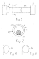
- Fig. 1 are shown as fixed parts of a transmission path for electrical energy two end terminations 1 and 2 schematically. Such end terminations are known, so that their structure is not discussed in more detail.
- a cryostat KR and a superconducting cable SK (FIG. Fig. 2 ) permanently connected.
- At least one of the end terminations 1 or 2 could also be a connecting sleeve.
- an indicated by a box 3 ring body RK present the structure and operation of the basis of Fig. 3 to 6 is explained.
- the cryostat KR is in accordance Fig. 2 of two coaxial and spaced apart tubes of metal, an outer tube 4 and an inner tube 5 between which a spacer and a vacuum insulation 6 are arranged.
- the tubes 4 and 5 are advantageously made of stainless steel. They can be corrugated transversely to their longitudinal direction and thus be easily bendable.
- the cryostat KR encloses, in addition to the cable SK, a cavity HR, through which a coolant can be passed.
- the structure of the superconducting cable SK is arbitrary. Also, two or more superconducting cables may be housed in the cryostat KR.
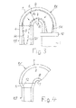
- Fig. 3 is shown schematically a bent by 180 ° annular body RK, which at one end with the cryostat KR and at the other end with the again only schematically indicated end termination 1 is connected.
- the annular body RK like the cryostat KR, consists of two tubes of metal arranged concentrically with one another, an outer tube 7 and an inner tube 8. Between the two tubes 7 and 8, a vacuum insulation 9 is provided.
- the tubes 7 and 8 are advantageously made of stainless steel. They can be corrugated transversely to their longitudinal direction.
- the tubes 7 and 8 can be designed with advantage but also as smooth tubes.
- the outer tube 7 of the annular body RK is firmly and tightly connected to the outer tube 4 of the cryostat KR. They are welded together, for example.
- the tubes 7 and 8 of the annular body RK are firmly and tightly connected at the other end, for example via a flange 10 with the end termination 1.
- the cable SK is mounted in the tubular body. It then projects so far out of the same at the end of the tubular body RK provided with the flange 10 that it can be connected to the end termination 1.
- the cable SK in the tubular body RK is advantageously arranged so that it rests against the inner tube 8, on the wall thereof, which is bent with the larger bending radius Ra. It is then accordingly Fig. 3 in the space enclosed by the tubular body RK as much as possible Outside. In this position, the cable SK is also connected to the end termination 1.
- the cable SK should be located in any case in the immediate vicinity of the mentioned wall of the inner tube 8 of the tubular body RK.
- the space enclosed by the tube body RK can advantageously be increased if the tubes 7 and 8, from which the tube body RK is bent, have a larger diameter than the corresponding tubes 4 and 5 of the cryostat KR. Is in Fig. 4 indicated, in which only the transition from the cryostat KR to the tubular body RK is shown. Between the pipes to be joined together in the illustrated embodiment, each about conically shaped transition pieces 11 and 12 are arranged. The transition pieces 11 and 12 may also have a different geometric shape. They are firmly connected in the end position with the tubes 4 and 5 of the cryostat KR and the tubes 7 and 8 of the tubular body RK, preferably welded.
- the method according to the invention is described above for a 150 m long cryostat KR, for which a 180 ° bent tubular body RK is sufficient.
- a longer cryostat with a correspondingly longer cable SK and the length of the tubular body RK must be extended so that a larger space for moving the cable SK is available.
- the tubular body RK can be extended, for example, by a pipe body bent by 90 ° or else by a tubular body which amounts to an even multiple of 90 °.
- a tubular body RK suitable for a 300 m long cryostat KR is bent by 360 °.
- a further elongated tubular body RK is also schematically shown in FIG Fig. 6 shown. It is bent by 540 ° and can be used with advantage for a 450 m cryostat KR.
- the tubular body RK can be assembled in all the described embodiments of prefabricated parts, which are each bent by 90 °. These parts are welded together. This can already be done in a manufacturing plant, but with advantage at the installation site.
Landscapes
- Superconductors And Manufacturing Methods Therefor (AREA)
- Containers, Films, And Cooling For Superconductive Devices (AREA)
- Thermal Insulation (AREA)
- Gas Or Oil Filled Cable Accessories (AREA)
Abstract
Description
- Die Erfindung bezieht sich auf ein Verfahren zum Aufbau einer Übertragungsstrecke für elektrische Energie, bei welchem mindestens ein supraleitfähiges Kabel und ein dasselbe umgebender Kryostat eingesetzt werden, der aus zwei konzentrisch zueinander angeordneten Rohren aus Metall besteht, einem äußeren Rohr und einem inneren Rohr, zwischen denen eine Vakuumisolierung angebracht ist, bei welchem der Kryostat im Montagezustand mit seinen Enden ebenso wie das in demselben befindliche supraleitfähige Kabel an feststehenden Teilen der Übertragungsstrecke angebracht wird und bei welchem durch den Kryostat zur Überführung des Kabels in den supraleitfähigen Zustand ein Kühlmittel geleitet wird (
EP 1 617 537 B1 ). - Feststehende Teile der Übertragungsstrecke können Endenabschlüsse oder Verbindungsmuffen sein, durch welche zwei aus Kryostat und Kabel bestehende Längen der Übertragungsstrecke miteinander verbunden werden. Ein solcher Kryostat besteht aus zwei Rohren, die durch eine Abstandshalterung voneinander getrennt sind. Sie sind dadurch konzentrisch zueinander angeordnet. Das Wort "konzentrisch" gilt dabei auch für einen Aufbau des Kryostats, in dem die beiden Rohre - bedingt durch Fertigungsungenauigkeiten - nicht exakt parallel zueinander verlaufen.
- Ein supraleitfähiges Kabel hat mindestens einen elektrischen Leiter aus einem Material, das bei ausreichend tiefen Temperaturen in den supraleitfähigen Zustand übergeht. Geeignete supraleitfähige Materialien sind beispielsweise oxidische Materialien auf Basis seltener Erden (ReBCO), insbesondere YBCO (Yttrium-Barium-Kupfer-Oxid), oder BSCCO (Wismut-Strontium-Kalzium-Kupfer-Oxid). Ausreichend niedrige Temperaturen, um ein derartiges Material in den supraleitfähigen Zustand zu bringen, liegen beispielsweise zwischen 67 K und 110 K. Es gibt aber auch supraleitfähige Materialien, wie beispielsweise Magnesiumdiborid, die auf noch tiefere Temperaturen abgekühlt werden müssen, wenn sie in den supraleitfähigen Zustand übergehen sollen. Geeignete Kühlmittel für all diese Materialien sind beispielsweise Stickstoff, Helium, Neon und Wasserstoff oder Gemische dieser Stoffe. Beim Betrieb einer Anordnung mit mindestens einem supraleitfähigen Kabel wird dasselbe also innerhalb des Kryostats erheblich - von Raumtemperatur auf Betriebstemperatur - abgekühlt, wodurch es infolge thermischer Kontraktion kürzer wird. Um die Funktionsfähigkeit der Übertragungsstrecke zu gewährleisten, müssen Vorkehrungen getroffen werden, durch welche die Verkürzung des Kabels ausgeglichen werden kann.
- Bei dem Verfahren nach der
EP 1 720 176 B1 wird ein supraleitfähiges Kabel in einem Kryostat so angebracht, dass es bei Raumtemperatur in Form einer Welle oder Wendel verläuft. Die dadurch gegenüber dem Kryostat erzielte Überlänge des Kabels wird durch ein kreuzartiges Netzwerk stabilisiert, das punktweise mit dem Kabel verbunden wird. - Aus der eingangs erwähnten
EP 1 617 537 B1 geht ein Verfahren zum Aufbau einer Anordnung mit einem in einem Kryostat verlegten supraleitfähigen Kabel hervor, das mit einem Endenabschluß verbunden ist. Der Endenabschluß wird mit einem elektrischen Leiter ausgerüstet, der mit einem rohrförmigen, radial federnde Lamellen aufweisenden Bauteil aus elektrisch leitendem Werkstoff bestückt wird, in welchem der Leiter des supraleitfähigen Kabels im Montagezustand eingebracht wird. Im Falle von thermisch bedingten Längenänderungen kann der Leiter des supraleitfähigen Kabels in seiner Längsrichtung in dem rohrförmigen Bauteil gleiten. - Der Erfindung liegt die Aufgabe zugrunde, das eingangs geschilderte Verfahren zum Aufbau einer Übertragungsstrecke für elektrische Energie zu vereinfachen.
- Diese Aufgabe wird gemäß der Erfindung dadurch gelöst,
- dass zumindest an einem Ende des Kryostats ein Rohrkörper lückenlos mit demselben verbunden wird, der um einen Winkel von mindestens 180° gebogen ist und der ebenfalls aus zwei konzentrisch zueinander angeordneten Rohren aus Metall besteht, einem äußeren Rohr und einem inneren Rohr, zwischen denen eine Vakuumisolierung angebracht ist,
- dass das aus dem Kryostat herausragende supraleitfähige Kabel bei Raumtemperatur derart in dem Rohrkörper angeordnet wird, dass es zumindest in unmittelbarer Nähe der den größeren Biegeradius aufweisenden Wandung des inneren Rohres verläuft, und
- dass der Rohrkörper mit seinem freien Ende sowie das von demselben umschlossene supraleitfähige Kabel an ein feststehendes Teil der Übertragungsstrecke angeschlossen werden.
- Der Rohrkörper kann in gebogener Form, in welcher er um einen Winkel von mindestens 180° gebogen ist, mit Vorteil in einer Werkstatt vorgefertigt werden. Er kann dann als einteiliges Bauteil zu einem Montageort transportiert und dort mit dem das supraleitfähige Kabel umgebenden Kryostat einer Übertragungsstrecke für elektrische Energie verbunden werden. Durch seine gebogene Form nimmt der Rohrkörper am Montageort relativ wenig Raum ein. Das ist insbesondere dann von Vorteil, wenn der Kryostat und das Kabel an eine Verbindungsmuffe angeschlossen werden sollen, die zum Verbinden mit einem weiterführenden Kryostat mit umschlossenem Kabel dient, weil dort in einer Baugrube in der Regel nur wenig Platz zur Verfügung steht. Das zumindest in der Nähe der Wandung des inneren Rohres des Rohrkörpers, die entsprechend dem größeren Biegeradius gebogen ist, verlegte Kabel kann sich bei Abkühlung und der damit verbundenen Kontraktion innerhalb des Rohrkörpers bewegen. Es liegt in der Ausgangsstellung bei Raumtemperatur mit größtem Biegeradius "außen" im Rohrkörper und es wird mit entsprechender Verkürzung seiner Länge im Rohrkörper nach "innen" bewegt, das heißt in Richtung der Wandung des inneren Rohres mit dem kleineren Biegeradius. Dabei wird auch die Verkürzung des supraleitfähigen Kabels in seiner Achsrichtung innerhalb des Kryostats ausgeglichen.
- Mit Vorteil wird das supraleitfähige Kabel bei seiner Montage im Rohrkörper so angeordnet, dass es an der Wandung des inneren Rohres desselben, die mit dem größeren Biegeradius gebogen ist, direkt anliegt. Die Montage wird dadurch vereinfacht und es steht dann der maximale Raum für die Bewegung des Kabels im Rohrkörper zur Verfügung.
- Der Winkel, um den der Rohrkörper gebogen ist, hängt von der Länge der Übertragungsstrecke ab. So gilt der Winkel von 180° beispielsweise für eine 150 m lange Übertragungsstrecke. Bei einer 300 m langen Übertragungsstrecke kann der Winkel beispielsweise bei 360° liegen. Ein Winkel von 540° ist mit Vorteil bei einer 450 m langen Übertragungsstrecke sinnvoll.
- Das Verfahren nach der Erfindung wird anhand der Zeichnungen als Ausführungsbeispiel erläutert.
- Es zeigen:
-
Fig. 1 in schematischer Darstellung eine für den Einsatz des Verfahrens nach der Erfindung geeignete Anordnung. -
Fig. 2 einen Schnitt durchFig. 1 längs der Linie II - II in vergrößerter Darstellung. -
Fig. 3 einen in der Anordnung nachFig. 1 einsetzbaren Rohrkörper. -
Fig. 4 eine gegenüberFig. 3 abgewandelte Ausführungsform eines Abschnitts des Rohrkörpers. -
Fig. 5 und 6 schematisch weitere Ausführungsformen des Rohrkörpers. - In
Fig. 1 sind als feststehende Teile einer Übertragungsstrecke für elektrische Energie zwei Endenabschlüsse 1 und 2 schematisch dargestellt. Derartige Endenabschlüsse sind bekannt, so daß auf ihren Aufbau nicht genauer eingegangen wird. An die beiden Endenabschlüsse 1 und 2 sind ein Kryostat KR und ein in demselben befindliches supraleitfähiges Kabel SK (Fig. 2 ) fest angeschlossen. Zumindest einer der Endenabschlüsse 1 oder 2 könnte auch eine Verbindungsmuffe sein. Zwischen dem Endenabschluß 1 und dem Kryostat KR ist in dem inFig. 1 dargestellten Ausführungsbeispiel ein durch ein Kästchen 3 angedeuteter Ringkörper RK vorhanden, dessen Aufbau und Funktionsweise anhand derFig. 3 bis 6 erläutert wird. - Der Kryostat KR besteht gemäß
Fig. 2 aus zwei koaxial und mit Abstand zueinander angeordneten Rohren aus Metall, einem äußeren Rohr 4 und einem inneren Rohr 5 zwischen denen eine Abstandshalterung und eine Vakuumisolierung 6 angeordnet sind. Die Rohre 4 und 5 bestehen mit Vorteil aus Edelstahl. Sie können quer zu ihrer Längsrichtung gewellt und damit gut biegbar sein. Der Kryostat KR umschließt neben dem Kabel SK einen Hohlraum HR, durch welchen ein Kühlmittel geleitet werden kann. Der Aufbau des supraleitfähigen Kabels SK ist beliebig. Es können auch zwei oder mehr supraleitfähige Kabel in dem Kryostat KR untergebracht sein. - In
Fig. 3 ist schematisch ein um 180° gebogener Ringkörper RK dargestellt, der an einem Ende mit dem Kryostat KR und am anderen Ende mit dem wieder nur schematisch angedeuteten Endenabschluß 1 verbunden ist. Der Ringkörper RK besteht ebenso wie der Kryostat KR aus zwei konzentrisch zueinander angeordneten Rohren aus Metall, einem äußeren Rohr 7 und einem inneren Rohr 8. Zwischen den beiden Rohren 7 und 8 ist eine Vakuumisolierung 9 angebracht. Die Rohre 7 und 8 bestehen mit Vorteil aus Edelstahl. Sie können quer zu ihrer Längsrichtung gewellt sein. Die Rohre 7 und 8 können mit Vorteil aber auch als Glattrohre ausgeführt sein. - In Montageposition ist das äußere Rohr 7 des Ringkörpers RK mit dem äußeren Rohr 4 des Kryostats KR fest und dicht verbunden. Sie sind beispielsweise miteinander verschweißt. Das gilt analog dazu auch für die inneren Rohre 8 und 5 von Ringkörper RK einerseits und Kryostat KR andererseits. Die Rohre 7 und 8 des Ringkörpers RK sind an dessen anderem Ende beispielsweise über eine Flanschverbindung 10 mit dem Endenabschluß 1 fest und dicht verbunden.
- Das Verfahren nach der Erfindung wird für die Ausführungsform einer Anordnung nach
Fig. 3 beispielsweise wie folgt durchgeführt: - Ein Kryostat KR mit einer Länge von etwa 150 m wird entlang einer Übertragungsstrecke so verlegt, dass sein eines Ende in der Nähe des Endenabschlusses 1 liegt. Das vom Kryostat KR umschlossene supraleitfähige Kabel SK ist in demselben mit Vorteil bereits im Herstellerwerk so angeordnet worden, dass es um eine vorgegebene Länge aus demselben herausragt. Es muß beim Transport des Kryostats KR zum Verlegeort durch eine geeignete Umhüllung von mechanischen Beschädigungen geschützt werden. Die Länge des herausragenden Kabels SK richtet sich nach der Länge des Rohrkörpers RK und nach der für einen Endenabschluß oder eine Verbindungsmuffe benötigten Länge.
- Vor dem geschilderten Verbinden von Rohrkörper RK und Kryostat KR wird das Kabel SK im Rohrkörper angebracht. Es ragt dann an dem mit dem Flansch 10 versehenen Ende des Rohrkörpers RK so weit aus demselben heraus, dass es an den Endenabschluß 1 angeschlossen werden kann. Dabei wird das Kabel SK im Rohrkörper RK mit Vorteil so angeordnet, dass es am inneren Rohr 8 desselben anliegt, und zwar an der Wandung desselben, die mit dem größeren Biegeradius Ra gebogen ist. Es liegt dann entsprechend
Fig. 3 im vom Rohrkörper RK umschlossenen Raum so weit wie möglich außen. In dieser Position wird das Kabel SK auch mit dem Endenabschluß 1 verbunden. Das Kabel SK soll auf jeden Fall in unmittelbarer Nähe der erwähnten Wandung des inneren Rohres 8 des Rohrkörpers RK liegen. - Nach im geschilderten Sinne fertiggestellter Montage des Rohrkörpers RK mit darin liegendem supraleitfähigem Kabel SK wird ein Kühlmittel durch den Kryostat KR geleitet. Dadurch wird das Kabel SK abgekühlt. Seine Länge wird dabei um etwa 0,3 % verkürzt. Diese Verkürzung wirkt sich einerseits in axialer Richtung innerhalb des Kryostats KR aber auch auf die im Rohrkörper RK untergebrachte Länge des Kabels SK aus. Das Kabel SK kann sich bedingt durch die Verkürzung innerhalb des Rohrkörpers RK bewegen, und zwar in Richtung der in
Fig. 3 eingezeichneten Pfeile nach "innen". Es kann in einer gestrichelt eingezeichneten, maximal erreichbaren Endposition an der Wandung des inneren Rohres 8 des Rohrkörpers RK anliegen, die mit dem kleineren Radius Ri gebogen ist. Auf diese Art und Weise wird der vom Rohrkörper RK umschlossene Raum ausgenutzt, um die Verkürzung des Kabels SK abzufangen, ohne dass dasselbe auf Zug beansprucht wird. - Der vom Rohrkörper RK umschlossene Raum kann mit Vorteil dann vergrößert werden, wenn die Rohre 7 und 8, aus welchen der Rohrkörper RK gebogen wird, einen größeren Durchmesser als die entsprechenden Rohre 4 und 5 des Kryostats KR haben. Das ist in
Fig. 4 angedeutet, in welcher nur der Übergang vom Kryostat KR zum Rohrkörper RK dargestellt ist. Zwischen den miteinander zu verbindenden Rohren sind im dargestellten Ausführungsbeispiel jeweils etwa konisch ausgeführte Übergangsstücke 11 und 12 angeordnet. Die Übergangsstücke 11 und 12 können auch eine andere geometrische Form haben. Sie sind in der Endposition mit den Rohren 4 und 5 des Kryostats KR sowie den Rohren 7 und 8 des Rohrkörpers RK fest verbunden, vorzugsweise verschweißt. Das Verfahren nach der Erfindung ist im Vorangehenden für einen 150 m langen Kryostat KR beschrieben, für den ein um 180° gebogener Rohrkörper RK ausreicht. Bei einem längeren Kryostat mit einem entsprechend längeren Kabel SK muß auch die Länge des Rohrkörpers RK verlängert werden, damit ein größerer Raum zur Bewegung des Kabels SK zur Verfügung steht. Der Rohrkörper RK kann beispielsweise durch einen um 90° gebogenen Rohrkörper verlängert werden oder auch um einen ein geradzahliges Vielfaches von 90° betragenden Rohrkörper. - Ein für einen 300 m langen Kryostat KR geeigneter Rohrkörper RK ist beispielsweise um 360° gebogen. Das ist in
Fig. 5 schematisch dargestellt, in welcher nur eine Linie eingezeichnet ist, die dem aus den Rohren 7 und 8 bestehenden Rohrkörper RK entspricht. Ein weiter verlängerter Rohrkörper RK ist ebenso schematisch inFig. 6 dargestellt. Er ist um 540° gebogen und kann mit Vorteil für einen 450 m langen Kryostat KR eingesetzt werden. - Der Rohrkörper RK kann in allen beschriebenen Ausführungsformen aus vorgefertigten Teilen zusammengesetzt werden, die jeweils um 90° gebogen sind. Diese Teile werden miteinander verschweißt. Das kann bereits in einem Herstellerwerk, mit Vorteil aber am Montageort durchgeführt werden.
Claims (4)
- Verfahren zum Aufbau einer Übertragungsstrecke für elektrische Energie, bei welchem mindestens ein supraleitfähiges Kabel und ein dasselbe umgebender Kryostat eingesetzt werden, der aus zwei konzentrisch zueinander angeordneten Rohren aus Metall besteht, einem äußeren Rohr und einem inneren Rohr, zwischen denen eine Vakuumisolierung angebracht ist, bei welchem der Kryostat im Montagezustand mit seinen Enden ebenso wie das in demselben befindliche supraleitfähige Kabel an feststehenden Teilen der Übertragungsstrecke angebracht wird und bei welchem durch den Kryostat zur Überführung des Kabels in den supraleitfähigen Zustand ein Kühlmittel geleitet wird, dadurch gekennzeichnet,- dass zumindest an einem Ende des Kryostats (KR) ein Rohrkörper (RK) lückenlos mit demselben verbunden wird, der um einen Winkel von mindestens 180° gebogen ist und der ebenfalls aus zwei konzentrisch zueinander angeordneten Rohren aus Metall besteht, einem äußeren Rohr (7) und einem inneren Rohr (8), zwischen denen eine Vakuumisolierung (9) angebracht ist,- dass das aus dem Kryostat (KR) herausragende supraleitfähige Kabel (SK) bei Raumtemperatur derart in dem Rohrkörper (RK) angeordnet wird, dass es zumindest in unmittelbarer Nähe der den größeren Biegeradius (Ra) aufweisenden Wandung des inneren Rohres (8) verläuft, und- dass der Rohrkörper (RK) mit seinem freien Ende sowie das von demselben umschlossene supraleitfähige Kabel (SK) an ein feststehendes Teil der Übertragungsstrecke angeschlossen werden.
- Verfahren nach Anspruch 1 oder 2, dadurch gekennzeichnet, dass der Rohrkörper (RK) in einem Herstellerwerk vorgefertigt, zu einem Montageort transportiert und dort mit dem Kryostat (KR) fest und dicht verbunden wird.
- Verfahren nach Anspruch 1 oder 2, dadurch gekennzeichnet, dass das supraleitfähige Kabel (SK) so im Rohrkörper (RK) angeordnet wird, dass es bei Raumtemperatur an der Wandung des inneren Rohrs (8) desselben anliegt, das mit dem größeren Biegeradius (Ra) gebogen ist.
- Verfahren nach einem der Ansprüche 1 bis 3, dadurch gekennzeichnet, dass für die Herstellung des Rohrkörpers (RK) Rohre (7,8) verwendet werden, die einen größeren Durchmesser als die entsprechenden Rohre (4,5) des Kryostats (KR) haben.
Priority Applications (7)
| Application Number | Priority Date | Filing Date | Title |
|---|---|---|---|
| EP16305709.4A EP3258562B1 (de) | 2016-06-13 | 2016-06-13 | Verfahren zum aufbau einer übertragungsstrecke für elektrische energie |
| DK16305709.4T DK3258562T3 (da) | 2016-06-13 | 2016-06-13 | Fremgangsmåde til opbygning af en overførselsstrækning for elektrisk energi |
| PCT/EP2017/063102 WO2017215912A1 (de) | 2016-06-13 | 2017-05-31 | Verfahren zum aufbau einer übertragungsstrecke für elektrische energie |
| US16/309,013 US10944250B2 (en) | 2016-06-13 | 2017-05-31 | Method for setting up a transmission link for electrical energy |
| KR1020197001100A KR102256548B1 (ko) | 2016-06-13 | 2017-05-31 | 전기 에너지 전송 링크를 설치하는 방법 |
| JP2018565025A JP6778766B2 (ja) | 2016-06-13 | 2017-05-31 | 電気エネルギーのための伝送リンクをセットアップする方法 |
| CN201780036758.2A CN109417281B (zh) | 2016-06-13 | 2017-05-31 | 用于构建电能传输路径件的方法 |
Applications Claiming Priority (1)
| Application Number | Priority Date | Filing Date | Title |
|---|---|---|---|
| EP16305709.4A EP3258562B1 (de) | 2016-06-13 | 2016-06-13 | Verfahren zum aufbau einer übertragungsstrecke für elektrische energie |
Publications (2)
| Publication Number | Publication Date |
|---|---|
| EP3258562A1 true EP3258562A1 (de) | 2017-12-20 |
| EP3258562B1 EP3258562B1 (de) | 2019-03-27 |
Family
ID=56368919
Family Applications (1)
| Application Number | Title | Priority Date | Filing Date |
|---|---|---|---|
| EP16305709.4A Active EP3258562B1 (de) | 2016-06-13 | 2016-06-13 | Verfahren zum aufbau einer übertragungsstrecke für elektrische energie |
Country Status (7)
| Country | Link |
|---|---|
| US (1) | US10944250B2 (de) |
| EP (1) | EP3258562B1 (de) |
| JP (1) | JP6778766B2 (de) |
| KR (1) | KR102256548B1 (de) |
| CN (1) | CN109417281B (de) |
| DK (1) | DK3258562T3 (de) |
| WO (1) | WO2017215912A1 (de) |
Families Citing this family (8)
| Publication number | Priority date | Publication date | Assignee | Title |
|---|---|---|---|---|
| US11488747B2 (en) * | 2018-06-28 | 2022-11-01 | Advanced Conductor Technologies Llc | Superconducting power cable system |
| CN113300292B (zh) * | 2020-02-21 | 2022-08-30 | 上海电缆研究所有限公司 | 一种用于超导电缆的敷设保护装置 |
| JP7899175B2 (ja) | 2020-11-18 | 2026-08-03 | ヴェイル,インコーポレイテッド | 懸垂型伝送線路又は地中伝送線路用の導体システム |
| US11581109B2 (en) * | 2020-11-18 | 2023-02-14 | VEIR, Inc. | Suspended superconducting transmission lines |
| KR20230129393A (ko) | 2020-11-18 | 2023-09-08 | 베어, 인크. | 초전도 전력 전송 선로들의 냉각을 위한 시스템들 및 방법들 |
| CN113720256B (zh) * | 2021-08-23 | 2024-01-30 | 中国科学院合肥物质科学研究院 | 一种测量超导带材临界弯曲半径的装置和方法 |
| US12548693B2 (en) | 2023-07-19 | 2026-02-10 | CERN—European Organization for Nuclear Research | Cryogenic link |
| FR3159056B1 (fr) | 2024-02-06 | 2026-06-12 | Nexans | Ensemble de connexion de deux câbles supraconducteurs |
Citations (5)
| Publication number | Priority date | Publication date | Assignee | Title |
|---|---|---|---|---|
| EP1480231A2 (de) * | 2003-05-20 | 2004-11-24 | Nexans | Verfahren zur Herstellung eines supraleitenden Kabels |
| EP1720176A1 (de) * | 2005-05-06 | 2006-11-08 | Nexans | Supraleiterkabel |
| EP1617537B1 (de) | 2004-07-16 | 2007-08-01 | Nexans | Endenabschluss |
| US20100285968A1 (en) * | 2009-05-05 | 2010-11-11 | Electric Power Research Institute, Inc. | Thermal contraction compensation for superconducting and cryo-resistive cables |
| EP2693584A1 (de) * | 2012-08-03 | 2014-02-05 | Nexans | Anordnung mit mindestens einem supraleitfähigen Kabel |
Family Cites Families (8)
| Publication number | Priority date | Publication date | Assignee | Title |
|---|---|---|---|---|
| US1685636A (en) * | 1928-01-20 | 1928-09-25 | Kemp Joseph | Tube-drawing plug |
| DE811945C (de) * | 1948-10-01 | 1951-08-23 | Otto Klein | Vorrichtung zum Wellen von Rohren |
| JPH08196030A (ja) * | 1995-01-13 | 1996-07-30 | Furukawa Electric Co Ltd:The | 極低温ケーブルの終端接続装置 |
| EP2209129B1 (de) * | 2009-01-15 | 2012-03-07 | Nexans | Anordnung zur Strombegrenzung |
| EP2369600B1 (de) * | 2010-03-04 | 2012-08-29 | Nexans | Supraleitfähiges elektrisches Gleichstrom-Kabel |
| DK2685469T3 (en) * | 2012-07-11 | 2017-08-14 | Nexans | Arrangement with at least one superconducting cable |
| DK2819247T3 (en) * | 2013-06-25 | 2018-12-03 | Nexans | Method for electrically conducting two superconducting cables |
| JP6140377B2 (ja) * | 2015-02-10 | 2017-05-31 | 古河電気工業株式会社 | 超電導ケーブル及び超電導ケーブルの製造方法 |
-
2016
- 2016-06-13 EP EP16305709.4A patent/EP3258562B1/de active Active
- 2016-06-13 DK DK16305709.4T patent/DK3258562T3/da active
-
2017
- 2017-05-31 WO PCT/EP2017/063102 patent/WO2017215912A1/de not_active Ceased
- 2017-05-31 US US16/309,013 patent/US10944250B2/en active Active
- 2017-05-31 CN CN201780036758.2A patent/CN109417281B/zh not_active Expired - Fee Related
- 2017-05-31 JP JP2018565025A patent/JP6778766B2/ja not_active Expired - Fee Related
- 2017-05-31 KR KR1020197001100A patent/KR102256548B1/ko active Active
Patent Citations (6)
| Publication number | Priority date | Publication date | Assignee | Title |
|---|---|---|---|---|
| EP1480231A2 (de) * | 2003-05-20 | 2004-11-24 | Nexans | Verfahren zur Herstellung eines supraleitenden Kabels |
| EP1617537B1 (de) | 2004-07-16 | 2007-08-01 | Nexans | Endenabschluss |
| EP1720176A1 (de) * | 2005-05-06 | 2006-11-08 | Nexans | Supraleiterkabel |
| EP1720176B1 (de) | 2005-05-06 | 2007-01-03 | Nexans | Supraleiterkabel |
| US20100285968A1 (en) * | 2009-05-05 | 2010-11-11 | Electric Power Research Institute, Inc. | Thermal contraction compensation for superconducting and cryo-resistive cables |
| EP2693584A1 (de) * | 2012-08-03 | 2014-02-05 | Nexans | Anordnung mit mindestens einem supraleitfähigen Kabel |
Non-Patent Citations (2)
| Title |
|---|
| HAMABE M ET AL: "Cooling cycle test of DC superconducting power transmission cable", JOURNAL OF PHYSICS: CONFERENCE SERIES, INSTITUTE OF PHYSICS PUBLISHING, BRISTOL, GB, vol. 234, no. 3, 22 July 2010 (2010-07-22), pages 32019, XP020193591, ISSN: 1742-6596, DOI: 10.1088/1742-6596/234/3/032019 * |
| MASASHI YAGI ET AL: "Successful Field Tests of the World's Longest 500-m High-Tc Superconducting Power Cable", FURUKAWA REVIEW, vol. 28, 1 January 2005 (2005-01-01), pages 53 - 60, XP055325376 * |
Also Published As
| Publication number | Publication date |
|---|---|
| CN109417281B (zh) | 2020-05-29 |
| JP6778766B2 (ja) | 2020-11-04 |
| JP2019526218A (ja) | 2019-09-12 |
| WO2017215912A1 (de) | 2017-12-21 |
| KR102256548B1 (ko) | 2021-05-27 |
| EP3258562B1 (de) | 2019-03-27 |
| DK3258562T3 (da) | 2019-07-01 |
| US20190260194A1 (en) | 2019-08-22 |
| KR20190016583A (ko) | 2019-02-18 |
| US10944250B2 (en) | 2021-03-09 |
| CN109417281A (zh) | 2019-03-01 |
Similar Documents
| Publication | Publication Date | Title |
|---|---|---|
| EP3258562B1 (de) | Verfahren zum aufbau einer übertragungsstrecke für elektrische energie | |
| EP2693584B1 (de) | Anordnung mit mindestens einem supraleitfähigen Kabel | |
| EP3281211B1 (de) | Vorrichtung zur gleichstromübertragung | |
| EP2228806B1 (de) | Anordnung zur Strombegrenzung | |
| EP2685469B1 (de) | Anordnung mit mindestens einem supraleitfähigen Kabel | |
| EP2418747B1 (de) | Anordnung zum elektrisch leitenden Verbinden von zwei elektrischen Einheiten | |
| EP1738376B1 (de) | Supraleitendes kabel und verfahren zur herstellung desselben | |
| EP2541560A1 (de) | Supraleiterkabel | |
| EP2830160A1 (de) | Verfahren zum elektrisch leitenden Verbinden von zwei supraleitfähigen Kabeln | |
| EP2426676A1 (de) | Anordnung mit mindestens einem supraleitfähigen Kabel | |
| EP2770514B1 (de) | Verfahren zum Kühlen eines supraleitfähigen Kabels | |
| EP2339593B1 (de) | Supraleitfähiges Kabelsystem | |
| DE102014224363A1 (de) | Vorrichtung der Supraleitungstechnik mitSpuleneinrichtungen und Kühlvorrichtung sowie damitausgestattetes Fahrzeug | |
| EP2071589B1 (de) | Supraleitfähiges elektrisches Kabel | |
| EP1821380B1 (de) | Verfahren zum Verlegen eines Supraleiterkabels | |
| EP2328156A1 (de) | Verfahren zum Betrieb einer Anordnung mit mindestens einem supraleitfähigen Kabel | |
| EP2819247A1 (de) | Verfahren zum elektrisch leitenden Verbinden von zwei supraleitfähigen Kabeln | |
| EP2317526B1 (de) | System mit mindestens einem supraleitfähigen Kabel | |
| WO2010108771A1 (de) | Supraleitfähiges elektrisches kabel | |
| EP2209129B1 (de) | Anordnung zur Strombegrenzung | |
| WO2015197337A1 (de) | Verfahren und anordnung zum aufbau eines supraleitfähigen kabelsystems | |
| DE1912840A1 (de) | Supraleiterkreis | |
| DE3027605C2 (de) | Vorrichtung zur Übertragung großer Kräfte | |
| DE2043445A1 (de) | Anordnung zur Halterung eines oder mehrerer supraleitfähiger Leiterstrange im Innern eines tiefstgekuhlten Kabels | |
| DE7038489U (de) | Gasgekuhlte Stromzuleitung |
Legal Events
| Date | Code | Title | Description |
|---|---|---|---|
| PUAI | Public reference made under article 153(3) epc to a published international application that has entered the european phase |
Free format text: ORIGINAL CODE: 0009012 |
|
| STAA | Information on the status of an ep patent application or granted ep patent |
Free format text: STATUS: REQUEST FOR EXAMINATION WAS MADE |
|
| 17P | Request for examination filed |
Effective date: 20170721 |
|
| AK | Designated contracting states |
Kind code of ref document: A1 Designated state(s): AL AT BE BG CH CY CZ DE DK EE ES FI FR GB GR HR HU IE IS IT LI LT LU LV MC MK MT NL NO PL PT RO RS SE SI SK SM TR |
|
| AX | Request for extension of the european patent |
Extension state: BA ME |
|
| GRAP | Despatch of communication of intention to grant a patent |
Free format text: ORIGINAL CODE: EPIDOSNIGR1 |
|
| STAA | Information on the status of an ep patent application or granted ep patent |
Free format text: STATUS: GRANT OF PATENT IS INTENDED |
|
| INTG | Intention to grant announced |
Effective date: 20181023 |
|
| GRAS | Grant fee paid |
Free format text: ORIGINAL CODE: EPIDOSNIGR3 |
|
| GRAA | (expected) grant |
Free format text: ORIGINAL CODE: 0009210 |
|
| STAA | Information on the status of an ep patent application or granted ep patent |
Free format text: STATUS: THE PATENT HAS BEEN GRANTED |
|
| AK | Designated contracting states |
Kind code of ref document: B1 Designated state(s): AL AT BE BG CH CY CZ DE DK EE ES FI FR GB GR HR HU IE IS IT LI LT LU LV MC MK MT NL NO PL PT RO RS SE SI SK SM TR |
|
| REG | Reference to a national code |
Ref country code: GB Ref legal event code: FG4D Free format text: NOT ENGLISH |
|
| REG | Reference to a national code |
Ref country code: CH Ref legal event code: EP |
|
| REG | Reference to a national code |
Ref country code: DE Ref legal event code: R096 Ref document number: 502016003904 Country of ref document: DE |
|
| REG | Reference to a national code |
Ref country code: AT Ref legal event code: REF Ref document number: 1114167 Country of ref document: AT Kind code of ref document: T Effective date: 20190415 |
|
| REG | Reference to a national code |
Ref country code: IE Ref legal event code: FG4D Free format text: LANGUAGE OF EP DOCUMENT: GERMAN |
|
| REG | Reference to a national code |
Ref country code: DK Ref legal event code: T3 Effective date: 20190628 |
|
| PG25 | Lapsed in a contracting state [announced via postgrant information from national office to epo] |
Ref country code: SE Free format text: LAPSE BECAUSE OF FAILURE TO SUBMIT A TRANSLATION OF THE DESCRIPTION OR TO PAY THE FEE WITHIN THE PRESCRIBED TIME-LIMIT Effective date: 20190327 Ref country code: LT Free format text: LAPSE BECAUSE OF FAILURE TO SUBMIT A TRANSLATION OF THE DESCRIPTION OR TO PAY THE FEE WITHIN THE PRESCRIBED TIME-LIMIT Effective date: 20190327 Ref country code: NO Free format text: LAPSE BECAUSE OF FAILURE TO SUBMIT A TRANSLATION OF THE DESCRIPTION OR TO PAY THE FEE WITHIN THE PRESCRIBED TIME-LIMIT Effective date: 20190627 Ref country code: FI Free format text: LAPSE BECAUSE OF FAILURE TO SUBMIT A TRANSLATION OF THE DESCRIPTION OR TO PAY THE FEE WITHIN THE PRESCRIBED TIME-LIMIT Effective date: 20190327 |
|
| REG | Reference to a national code |
Ref country code: NL Ref legal event code: MP Effective date: 20190327 |
|
| PG25 | Lapsed in a contracting state [announced via postgrant information from national office to epo] |
Ref country code: BG Free format text: LAPSE BECAUSE OF FAILURE TO SUBMIT A TRANSLATION OF THE DESCRIPTION OR TO PAY THE FEE WITHIN THE PRESCRIBED TIME-LIMIT Effective date: 20190627 Ref country code: RS Free format text: LAPSE BECAUSE OF FAILURE TO SUBMIT A TRANSLATION OF THE DESCRIPTION OR TO PAY THE FEE WITHIN THE PRESCRIBED TIME-LIMIT Effective date: 20190327 Ref country code: NL Free format text: LAPSE BECAUSE OF FAILURE TO SUBMIT A TRANSLATION OF THE DESCRIPTION OR TO PAY THE FEE WITHIN THE PRESCRIBED TIME-LIMIT Effective date: 20190327 Ref country code: HR Free format text: LAPSE BECAUSE OF FAILURE TO SUBMIT A TRANSLATION OF THE DESCRIPTION OR TO PAY THE FEE WITHIN THE PRESCRIBED TIME-LIMIT Effective date: 20190327 Ref country code: LV Free format text: LAPSE BECAUSE OF FAILURE TO SUBMIT A TRANSLATION OF THE DESCRIPTION OR TO PAY THE FEE WITHIN THE PRESCRIBED TIME-LIMIT Effective date: 20190327 Ref country code: GR Free format text: LAPSE BECAUSE OF FAILURE TO SUBMIT A TRANSLATION OF THE DESCRIPTION OR TO PAY THE FEE WITHIN THE PRESCRIBED TIME-LIMIT Effective date: 20190628 |
|
| PG25 | Lapsed in a contracting state [announced via postgrant information from national office to epo] |
Ref country code: AL Free format text: LAPSE BECAUSE OF FAILURE TO SUBMIT A TRANSLATION OF THE DESCRIPTION OR TO PAY THE FEE WITHIN THE PRESCRIBED TIME-LIMIT Effective date: 20190327 Ref country code: CZ Free format text: LAPSE BECAUSE OF FAILURE TO SUBMIT A TRANSLATION OF THE DESCRIPTION OR TO PAY THE FEE WITHIN THE PRESCRIBED TIME-LIMIT Effective date: 20190327 Ref country code: ES Free format text: LAPSE BECAUSE OF FAILURE TO SUBMIT A TRANSLATION OF THE DESCRIPTION OR TO PAY THE FEE WITHIN THE PRESCRIBED TIME-LIMIT Effective date: 20190327 Ref country code: SK Free format text: LAPSE BECAUSE OF FAILURE TO SUBMIT A TRANSLATION OF THE DESCRIPTION OR TO PAY THE FEE WITHIN THE PRESCRIBED TIME-LIMIT Effective date: 20190327 Ref country code: PT Free format text: LAPSE BECAUSE OF FAILURE TO SUBMIT A TRANSLATION OF THE DESCRIPTION OR TO PAY THE FEE WITHIN THE PRESCRIBED TIME-LIMIT Effective date: 20190727 Ref country code: EE Free format text: LAPSE BECAUSE OF FAILURE TO SUBMIT A TRANSLATION OF THE DESCRIPTION OR TO PAY THE FEE WITHIN THE PRESCRIBED TIME-LIMIT Effective date: 20190327 Ref country code: IT Free format text: LAPSE BECAUSE OF FAILURE TO SUBMIT A TRANSLATION OF THE DESCRIPTION OR TO PAY THE FEE WITHIN THE PRESCRIBED TIME-LIMIT Effective date: 20190327 Ref country code: RO Free format text: LAPSE BECAUSE OF FAILURE TO SUBMIT A TRANSLATION OF THE DESCRIPTION OR TO PAY THE FEE WITHIN THE PRESCRIBED TIME-LIMIT Effective date: 20190327 |
|
| PG25 | Lapsed in a contracting state [announced via postgrant information from national office to epo] |
Ref country code: SM Free format text: LAPSE BECAUSE OF FAILURE TO SUBMIT A TRANSLATION OF THE DESCRIPTION OR TO PAY THE FEE WITHIN THE PRESCRIBED TIME-LIMIT Effective date: 20190327 Ref country code: PL Free format text: LAPSE BECAUSE OF FAILURE TO SUBMIT A TRANSLATION OF THE DESCRIPTION OR TO PAY THE FEE WITHIN THE PRESCRIBED TIME-LIMIT Effective date: 20190327 |
|
| PG25 | Lapsed in a contracting state [announced via postgrant information from national office to epo] |
Ref country code: IS Free format text: LAPSE BECAUSE OF FAILURE TO SUBMIT A TRANSLATION OF THE DESCRIPTION OR TO PAY THE FEE WITHIN THE PRESCRIBED TIME-LIMIT Effective date: 20190727 |
|
| REG | Reference to a national code |
Ref country code: DE Ref legal event code: R097 Ref document number: 502016003904 Country of ref document: DE |
|
| PG25 | Lapsed in a contracting state [announced via postgrant information from national office to epo] |
Ref country code: MC Free format text: LAPSE BECAUSE OF FAILURE TO SUBMIT A TRANSLATION OF THE DESCRIPTION OR TO PAY THE FEE WITHIN THE PRESCRIBED TIME-LIMIT Effective date: 20190327 |
|
| REG | Reference to a national code |
Ref country code: CH Ref legal event code: PL |
|
| PLBE | No opposition filed within time limit |
Free format text: ORIGINAL CODE: 0009261 |
|
| STAA | Information on the status of an ep patent application or granted ep patent |
Free format text: STATUS: NO OPPOSITION FILED WITHIN TIME LIMIT |
|
| PG25 | Lapsed in a contracting state [announced via postgrant information from national office to epo] |
Ref country code: SI Free format text: LAPSE BECAUSE OF FAILURE TO SUBMIT A TRANSLATION OF THE DESCRIPTION OR TO PAY THE FEE WITHIN THE PRESCRIBED TIME-LIMIT Effective date: 20190327 |
|
| 26N | No opposition filed |
Effective date: 20200103 |
|
| REG | Reference to a national code |
Ref country code: BE Ref legal event code: MM Effective date: 20190630 |
|
| PG25 | Lapsed in a contracting state [announced via postgrant information from national office to epo] |
Ref country code: TR Free format text: LAPSE BECAUSE OF FAILURE TO SUBMIT A TRANSLATION OF THE DESCRIPTION OR TO PAY THE FEE WITHIN THE PRESCRIBED TIME-LIMIT Effective date: 20190327 |
|
| PG25 | Lapsed in a contracting state [announced via postgrant information from national office to epo] |
Ref country code: IE Free format text: LAPSE BECAUSE OF NON-PAYMENT OF DUE FEES Effective date: 20190613 |
|
| PG25 | Lapsed in a contracting state [announced via postgrant information from national office to epo] |
Ref country code: BE Free format text: LAPSE BECAUSE OF NON-PAYMENT OF DUE FEES Effective date: 20190630 Ref country code: LI Free format text: LAPSE BECAUSE OF NON-PAYMENT OF DUE FEES Effective date: 20190630 Ref country code: CH Free format text: LAPSE BECAUSE OF NON-PAYMENT OF DUE FEES Effective date: 20190630 Ref country code: LU Free format text: LAPSE BECAUSE OF NON-PAYMENT OF DUE FEES Effective date: 20190613 |
|
| GBPC | Gb: european patent ceased through non-payment of renewal fee |
Effective date: 20200613 |
|
| PG25 | Lapsed in a contracting state [announced via postgrant information from national office to epo] |
Ref country code: GB Free format text: LAPSE BECAUSE OF NON-PAYMENT OF DUE FEES Effective date: 20200613 |
|
| PG25 | Lapsed in a contracting state [announced via postgrant information from national office to epo] |
Ref country code: CY Free format text: LAPSE BECAUSE OF FAILURE TO SUBMIT A TRANSLATION OF THE DESCRIPTION OR TO PAY THE FEE WITHIN THE PRESCRIBED TIME-LIMIT Effective date: 20190327 |
|
| PG25 | Lapsed in a contracting state [announced via postgrant information from national office to epo] |
Ref country code: MT Free format text: LAPSE BECAUSE OF FAILURE TO SUBMIT A TRANSLATION OF THE DESCRIPTION OR TO PAY THE FEE WITHIN THE PRESCRIBED TIME-LIMIT Effective date: 20190327 Ref country code: HU Free format text: LAPSE BECAUSE OF FAILURE TO SUBMIT A TRANSLATION OF THE DESCRIPTION OR TO PAY THE FEE WITHIN THE PRESCRIBED TIME-LIMIT; INVALID AB INITIO Effective date: 20160613 |
|
| PG25 | Lapsed in a contracting state [announced via postgrant information from national office to epo] |
Ref country code: MK Free format text: LAPSE BECAUSE OF FAILURE TO SUBMIT A TRANSLATION OF THE DESCRIPTION OR TO PAY THE FEE WITHIN THE PRESCRIBED TIME-LIMIT Effective date: 20190327 |
|
| REG | Reference to a national code |
Ref country code: AT Ref legal event code: MM01 Ref document number: 1114167 Country of ref document: AT Kind code of ref document: T Effective date: 20210613 |
|
| PG25 | Lapsed in a contracting state [announced via postgrant information from national office to epo] |
Ref country code: AT Free format text: LAPSE BECAUSE OF NON-PAYMENT OF DUE FEES Effective date: 20210613 |
|
| PGFP | Annual fee paid to national office [announced via postgrant information from national office to epo] |
Ref country code: DK Payment date: 20260624 Year of fee payment: 11 |
|
| PGFP | Annual fee paid to national office [announced via postgrant information from national office to epo] |
Ref country code: DE Payment date: 20260622 Year of fee payment: 11 |
|
| PGFP | Annual fee paid to national office [announced via postgrant information from national office to epo] |
Ref country code: FR Payment date: 20260626 Year of fee payment: 11 |