EP3258224B1 - Spacer for holding a distance between a rod-shaped conductor and an external conductor of a fill level measuring probe - Google Patents
Spacer for holding a distance between a rod-shaped conductor and an external conductor of a fill level measuring probe Download PDFInfo
- Publication number
- EP3258224B1 EP3258224B1 EP16174228.3A EP16174228A EP3258224B1 EP 3258224 B1 EP3258224 B1 EP 3258224B1 EP 16174228 A EP16174228 A EP 16174228A EP 3258224 B1 EP3258224 B1 EP 3258224B1
- Authority
- EP
- European Patent Office
- Prior art keywords
- rod
- spacer
- shaped inner
- inner conductor
- support elements
- Prior art date
- Legal status (The legal status is an assumption and is not a legal conclusion. Google has not performed a legal analysis and makes no representation as to the accuracy of the status listed.)
- Active
Links
- 239000004020 conductor Substances 0.000 title claims description 257
- 125000006850 spacer group Chemical group 0.000 title claims description 195
- 239000000523 sample Substances 0.000 title claims description 59
- 238000000034 method Methods 0.000 claims description 13
- 239000000463 material Substances 0.000 claims description 8
- 239000004033 plastic Substances 0.000 claims description 3
- 230000002040 relaxant effect Effects 0.000 claims 1
- 238000005259 measurement Methods 0.000 description 6
- 239000004696 Poly ether ether ketone Substances 0.000 description 4
- 229920002530 polyetherether ketone Polymers 0.000 description 4
- 230000035939 shock Effects 0.000 description 3
- 230000005540 biological transmission Effects 0.000 description 2
- 230000036316 preload Effects 0.000 description 2
- 238000002310 reflectometry Methods 0.000 description 2
- 230000002787 reinforcement Effects 0.000 description 2
- 230000007704 transition Effects 0.000 description 2
- 238000013459 approach Methods 0.000 description 1
- 238000011109 contamination Methods 0.000 description 1
- 230000001419 dependent effect Effects 0.000 description 1
- 239000013013 elastic material Substances 0.000 description 1
- 230000002349 favourable effect Effects 0.000 description 1
- 230000001771 impaired effect Effects 0.000 description 1
- 230000000284 resting effect Effects 0.000 description 1
- 239000000126 substance Substances 0.000 description 1
Images


Classifications
-
- G—PHYSICS
- G01—MEASURING; TESTING
- G01F—MEASURING VOLUME, VOLUME FLOW, MASS FLOW OR LIQUID LEVEL; METERING BY VOLUME
- G01F23/00—Indicating or measuring liquid level or level of fluent solid material, e.g. indicating in terms of volume or indicating by means of an alarm
- G01F23/0046—Indicating or measuring liquid level or level of fluent solid material, e.g. indicating in terms of volume or indicating by means of an alarm with a stationary probe, where a liquid specimen is separated from the mean mass and measured
-
- G—PHYSICS
- G01—MEASURING; TESTING
- G01B—MEASURING LENGTH, THICKNESS OR SIMILAR LINEAR DIMENSIONS; MEASURING ANGLES; MEASURING AREAS; MEASURING IRREGULARITIES OF SURFACES OR CONTOURS
- G01B5/00—Measuring arrangements characterised by the use of mechanical techniques
- G01B5/02—Measuring arrangements characterised by the use of mechanical techniques for measuring length, width or thickness
- G01B5/06—Measuring arrangements characterised by the use of mechanical techniques for measuring length, width or thickness for measuring thickness
- G01B5/061—Measuring arrangements characterised by the use of mechanical techniques for measuring length, width or thickness for measuring thickness height gauges
-
- G—PHYSICS
- G01—MEASURING; TESTING
- G01F—MEASURING VOLUME, VOLUME FLOW, MASS FLOW OR LIQUID LEVEL; METERING BY VOLUME
- G01F23/00—Indicating or measuring liquid level or level of fluent solid material, e.g. indicating in terms of volume or indicating by means of an alarm
- G01F23/22—Indicating or measuring liquid level or level of fluent solid material, e.g. indicating in terms of volume or indicating by means of an alarm by measuring physical variables, other than linear dimensions, pressure or weight, dependent on the level to be measured, e.g. by difference of heat transfer of steam or water
- G01F23/28—Indicating or measuring liquid level or level of fluent solid material, e.g. indicating in terms of volume or indicating by means of an alarm by measuring physical variables, other than linear dimensions, pressure or weight, dependent on the level to be measured, e.g. by difference of heat transfer of steam or water by measuring the variations of parameters of electromagnetic or acoustic waves applied directly to the liquid or fluent solid material
- G01F23/284—Electromagnetic waves
-
- B—PERFORMING OPERATIONS; TRANSPORTING
- B25—HAND TOOLS; PORTABLE POWER-DRIVEN TOOLS; MANIPULATORS
- B25B—TOOLS OR BENCH DEVICES NOT OTHERWISE PROVIDED FOR, FOR FASTENING, CONNECTING, DISENGAGING OR HOLDING
- B25B27/00—Hand tools, specially adapted for fitting together or separating parts or objects whether or not involving some deformation, not otherwise provided for
- B25B27/02—Hand tools, specially adapted for fitting together or separating parts or objects whether or not involving some deformation, not otherwise provided for for connecting objects by press fit or detaching same
- B25B27/06—Hand tools, specially adapted for fitting together or separating parts or objects whether or not involving some deformation, not otherwise provided for for connecting objects by press fit or detaching same inserting or withdrawing sleeves or bearing races
-
- H—ELECTRICITY
- H01—ELECTRIC ELEMENTS
- H01P—WAVEGUIDES; RESONATORS, LINES, OR OTHER DEVICES OF THE WAVEGUIDE TYPE
- H01P3/00—Waveguides; Transmission lines of the waveguide type
- H01P3/02—Waveguides; Transmission lines of the waveguide type with two longitudinal conductors
- H01P3/06—Coaxial lines
Definitions
- the present invention relates to a spacer for maintaining a distance between a rod-shaped inner conductor and an outer conductor of a level measuring probe.
- the invention also relates to a rod-shaped inner conductor of a measuring probe, a measuring probe for determining a fill level of a medium located in a container, and an assembly method for assembling a spacer on a rod-shaped inner conductor.
- Time domain reflectometry which is also known as Time Domain Reflectometry (TDR) is used to determine and analyze run lengths and reflection characteristics of electromagnetic waves and signals.
- TDR Time Domain Reflectometry
- an electromagnetic pulse is generated by the electronics of the sensor, coupled into a conductor, which is also referred to as a measuring probe, and guided along this probe.
- a conductor which is also referred to as a measuring probe
- coaxial measuring probes are used in which a rod-shaped inner conductor CGS: PSU
- the electromagnetic pulse After the electromagnetic pulse has been coupled into the measuring probe, it is now reflected on the surface of the medium to be measured and runs back along the measuring probe to an electronics unit, which then calculates the level from the time difference between the transmitted and received pulse.
- Such a measuring probe can be exposed to vibrations or external shocks, so that this can result in inaccuracies in the measurement.
- the DE 10 2011 009 385 A1 describes a spacer for centering an inner conductor in an outer conductor of a coaxial conductor.
- An outer ring resting on the inner wall of the outer conductor is provided as a support structure, with at least two ring segments spaced around the circumference of the inner rod being provided to form a central opening, which are connected to the outer ring via spoke-like webs.
- the US 6,380,750 B1 describes a measuring probe in which a spacer is provided for spacing an outer conductor from an inner conductor.
- the spacer surrounds the outer conductor in the assembled state.
- spacer elements are provided on the inner surface of the ring segment of the spacer.
- a spacer for maintaining a distance between a rod-shaped inner conductor and an outer conductor of a level measuring probe has an annular element and at least three support elements which each protrude in a radial direction from an inner surface of the annular element.
- Each of the three support elements has a curved end face at an end facing away from the inner face. The end facing away from the inner surface is designed to engage in a recess in the rod-shaped inner conductor.
- a coaxial measuring probe which is also referred to below as a fill level measuring probe or simply as a measuring probe.
- the suitability of such measuring probes can be improved in systems with vibration loads. For example, when measuring the level, vibration loads or external shocks can occur, which can impair the measurement result.
- the spacer makes it possible to reduce the relative movement between the rod-shaped inner conductor and the outer conductor of the measuring probe even in the event of vibration loads. At the same time, electrical deviations in the measurement signal per spacer can be kept low.
- HF interference signals that is to say high-frequency interference signals, can be reduced compared to conventional connecting means for connecting the rod-shaped inner conductor and the outer conductor.
- the annular element has, for example, the shape of a tubular segment.
- the annular element can be a thin-walled tubular segment, for example in the form of a thin-walled cylinder.
- the ring-shaped element can have the shape of a section of a cylinder jacket.
- the ring-shaped element has a cylindrical inner surface and a cylindrical outer surface.
- the three support elements protrude from the cylindrical inner surface in the radial direction to a center point of the annular element.
- the respective support elements can be arranged along a circumferential direction of the annular element at regular intervals from one another on the inner surface. For example, the angle between each support element, in particular between the radial directions of the support elements, with respect to the circumferential direction of the annular element is 120 °.
- the three support elements each have an end facing away from the inner surface.
- the curved end face which is, for example, a simply curved surface.
- a single curved surface means that the surface is curved only in one direction and has no curvature in a further direction.
- the curved end face can, for example, be a segment of a cylinder jacket surface.
- Each of the three support elements can furthermore have an end facing the inner surface, at which the respective support element is fastened to the inner surface of the annular element. Between this end facing the inner surface and the inner surface itself, a radius can be provided as a transition from the inner surface to the respective support element.
- the spacer can have a flexible or elastic material, so that the spacer can be positioned on the rod-shaped inner conductor with the aid of an assembly tool and then the outer conductor can be placed over the spacer.
- the end of the support elements facing away from the inner surface is designed to engage in a recess of the rod-shaped inner conductor.
- the rod-shaped inner conductor also has three recesses for this purpose, which correspond to the respective support element of the spacer, so that the end of the respective support element facing away from the inner surface can engage in the corresponding recess of the rod-shaped inner conductor.
- the radius of the curved end face of the end facing away from the inner surface differs from a radius of a surface of the rod-shaped inner conductor.
- the radius of the curved end face can match the radius of the surface of the rod-shaped inner conductor while the spacer is positioned on the rod-shaped inner conductor. This aspect will be explained in more detail below and in the description of the figures.
- the at least three support elements taper in the radial direction.
- the radial direction represents, for example, a central axis of the respective support element.
- the radial direction is a radial direction in relation to the annular element, that is, the radial direction runs through the center of the annular element.
- the cross-sectional area of the support element perpendicular to the radial direction at an end facing the inner surface of the annular element is larger than a cross-sectional area of the support element at the end of the support element remote from the inner surface.
- the at least three support elements can have a circular or oval cross-sectional area.
- the shape of the cross-sectional area of the respective support element can change in the radial direction.
- the cross-sectional area at an end facing the inner surface of the annular element can have an oval shape, the cross-sectional area of the end facing away from the inner surface having a circular shape.
- the at least three support elements are arranged at regular intervals along a circumferential direction of the annular element.
- the circumferential direction denotes that direction which extends along the cylindrical inner surface or the cylindrical outer surface of the annular element.
- the support elements can each be arranged at equal distances from one another on the inner surface of the annular element.
- An angle of 120 ° can be provided between the respective support elements.
- a correspondingly smaller angle can be provided between the individual support elements, the support elements in turn being arranged at equal intervals along the circumferential direction on the inner surface of the annular element. In this way, a uniform force transmission between the rod-shaped inner conductor and the outer conductor of the measuring probe can be achieved in the event of a vibration load.
- the support elements can be guided past a surface of the rod-shaped inner conductor during the assembly of the spacer on the rod-shaped inner conductor. This will be explained in more detail in the further course of the description.
- the curved end face of the respective support element has a radius, the center of which does not lie on an axis of rotation of the annular element or of the spacer.
- the radius of the curved end face can be chosen so that when the spacer or the annular element is deformed during assembly, optimal guidability of the curved end faces of the support elements over a surface of the rod-shaped inner conductor is ensured.
- the curved end faces of the support elements can be shifted, for example by 0.3 mm each, with respect to the center point of the annular element.
- the curved end faces are moved away from the center.
- the curved end faces or the bearing surfaces of the support elements are accordingly designed in such a way that the deformation path for pushing onto the rod-shaped Inner conductor is as small as possible during assembly in order to avoid damage to the spacer when expanding.
- the radius of the curved end face corresponds to the radius of the surface of the rod-shaped inner conductor.
- the radius of the curved end face during the deformation, i.e. during the assembly of the spacer on the rod-shaped inner conductor corresponds to the radius of the surface of the rod-shaped inner conductor, but the center point of the radius of the curved end face lies before or after assembly, that is in the relaxed state of the spacer, not on the axis of rotation of the annular element.
- the curved end face is designed to ensure optimal guidance of the spacer over the surface of the rod-shaped element during assembly.
- the at least three support elements each have a bore.
- the bore axes of the bores running through the support elements are each arranged inclined with respect to an axis of rotation of the annular element.
- the axis of rotation of the ring-shaped element in turn runs through the center of the ring-shaped element.
- Inclined bores are thus provided in the respective support elements, the bores being designed to receive a pin element of an assembly tool.
- the bore axes of the respective support elements can be inclined by about 0 ° to 20 °, preferably by about 0 ° to 10 ° and in particular by about 2.5 °, with respect to the axis of rotation of the annular element.
- the bores of the respective support elements can run through a central axis of the support elements which, for example, lies in the radial direction of the respective support elements.
- the respective bore axes of the bores running through the support elements intersect at a common point which lies on the axis of rotation of the annular element.
- all the bore axes of the support elements have the same inclination with respect to the axis of rotation of the annular element.
- This inclination is predetermined by the alignment of the pin elements of an assembly tool to be received through the bores.
- it is possible to expand or pretension the spacer by the pin elements of the assembly tool to be received, in order thus to mount the spacer on the rod-shaped inner conductor.
- the annular element has a cylindrical outer surface.
- the spacer is made from a plastic material.
- the spacer is possible for the spacer to be made from polyetheretherketone (PEEK).
- PEEK polyetheretherketone
- Such a material can ensure high strength over a wide temperature range, and such a material is also chemically resistant. This is particularly advantageous because the spacer can come into contact with the respective medium to be measured when measuring the fill level.
- a rod-shaped inner conductor of a measuring probe is specified.
- the rod-shaped inner conductor has a first row with at least three recesses along a circumferential direction of the rod-shaped inner conductor for receiving a support element of a spacer, in particular the spacer described above.
- the recesses each have a curved base area with a radius, the center of which does not lie on an axis of rotation of the rod-shaped inner conductor.
- the recesses are provided as blind holes.
- the recesses in the form of depressions in the surface of the rod-shaped inner conductor can be provided on a surface of the rod-shaped inner conductor.
- the recesses can be provided in the form of bores in the rod-shaped inner conductor, the base of the recesses assuming a simply curved shape.
- simply curved base area means that the base area is bent along one direction, for example along a circumferential direction of the rod-shaped inner conductor, and has no curvature along a further direction, which is, for example, parallel to the axis of rotation of the rod-shaped inner conductor.
- the curved base of the recess has the same curvature as the curved end face on the end of the support element of the spacer facing away from the inner surface.
- the end facing away from the inner surface in particular the curved end face of the support element of the spacer, can rest on the curved base surface of the rod-shaped inner conductor.
- the depressions that is to say the recesses, are formed in the rod-shaped inner conductor for optimal support with the same radius as the curved end face of the support elements of the spacer.
- the curved base of the recess is simply curved.
- An axis of rotation of the simply curved base surface of the recess and the axis of rotation of the rod-shaped inner conductor are spaced apart from one another.
- the curved base of the recesses is adapted to the curved end face of the support elements of the spacer.
- each curved base surface has a radius, the center of which lies on its own axis of rotation, the axes of rotation of the curved base surfaces of each recess being spaced from one another.
- the rod-shaped inner conductor also has a second row with at least three recesses along a circumferential direction of the rod-shaped inner conductor for receiving a support element of a spacer, in particular the spacer described above.
- the second row with the at least three recesses and the first row with the at least three recesses are spaced apart from one another along the axis of rotation of the rod-shaped inner conductor. Further rows with at least three recesses in the rod-shaped inner conductor are also possible.
- spacers can thus be provided on the rod-shaped inner conductor.
- exactly two spacers are provided between the rod-shaped inner conductor and the outer conductor in order to improve the vibration properties of the measuring probe.
- the support elements of a first spacer can, for example, engage in the first row of recesses, the support elements of a second spacer engage in the second row of recesses in the rod-shaped inner conductor.
- a measuring probe for determining a fill level of a medium located in a container has at least one spacer, a rod-shaped inner conductor with at least three recesses along a circumferential direction of the rod-shaped inner conductor, and an outer conductor.
- the spacer can be the spacer described above with the corresponding features.
- the rod-shaped inner conductor can also be the rod-shaped inner conductor described above.
- the spacer is designed to hold the outer conductor and the rod-shaped inner conductor essentially coaxially to one another by engaging the support elements in the recesses of the rod-shaped inner conductor.
- the curved end faces of the respective support elements of the spacer can rest on the corresponding curved base surfaces of the respective recesses of the rod-shaped inner conductor.
- a firm fit can thus be provided between the rod-shaped inner conductor and the spacer.
- an almost tight fit of the spacer in the outer conductor can be ensured by a small air gap between the cylindrical outer surface of the annular element and an inner surface of the outer conductor. It is also possible that no air gap is provided so that a firm, play-free fit is created.
- the rod-shaped inner conductor can be guaranteed to be seated tightly or almost completely in the outer conductor of the measuring probe, and improved overall stability of the measuring probe with respect to vibration loads can be achieved.
- the rod-shaped inner conductor and the outer conductor are aligned essentially coaxially to one another by means of two spacers spaced apart from one another along an axis of rotation of the rod-shaped inner conductor.
- the forces acting are transmitted from the outer conductor to the spacer via the outer surface of the spacer and are further transmitted to the rod-shaped inner conductor via the support elements of the spacer. Accordingly, the power transmission also takes place in the opposite direction.
- the annular element of the spacer has a cylindrical outer surface.
- An air gap is provided between the cylindrical outer surface of the annular element and an inner surface of the outer conductor.
- the cylindrical outer surface of the ring-shaped element can have a dimension which corresponds to the inner surface of the outer conductor of the measuring probe, so that a predetermined distance or an air gap can be provided between the spacer and the outer conductor. This in turn ensures that the outer conductor of the fill level measuring probe sits almost free of play on the rod-shaped inner conductor, so that an improved resistance of the fill level measuring probe to vibration loads or to external shocks can be achieved. The influence of vibration movements of the level measuring probe on the measurement result can thus be reduced.
- the structure of the spacer enables simple assembly of the Coaxial level measuring probe made of rod-shaped inner conductor and outer conductor can be guaranteed.
- a tool for mounting a spacer, as described above, on a rod-shaped inner conductor is specified.
- the tool is designed to position the spacer on the rod-shaped inner conductor so that the support elements of the spacer can be brought into engagement with the recesses of the rod-shaped inner conductor.
- the tool has an annular clamping device with at least three pin elements.
- the pin elements each have a longitudinal direction and are movably mounted in the ring-shaped clamping device in such a way that the longitudinal axes of the respective pin elements always intersect at one point.
- the pin elements can be arranged at regular intervals along a circumferential direction on an end face of the annular clamping device. For example, an angle between the respective pin elements in relation to the circumferential direction is in each case 120 °.
- the pin elements can be designed to preload the spacer for mounting on the rod-shaped inner conductor by shifting the tool along the axis of rotation of the annular element so that the pin elements, which are inclined relative to the axis of rotation of the annular element, enter the bores of the support elements be inserted.
- the pin elements are designed to engage in the bores provided in the support elements of the spacer, wherein pushing the pin elements of the tool into the bores of the support elements leads to an expansion or pretensioning of the spacer.
- the spacer is expanded so that the support elements can be guided over the surface of the rod-shaped inner conductor to position the spacer at the appropriate point on the rod-shaped inner conductor.
- the pin elements can be pulled out of the bores of the support elements again, so that the spacer relaxes again and the support elements of the spacer come into engagement with the recesses of the rod-shaped inner conductor.
- a mounting method for mounting a spacer, as described above, on a rod-shaped inner conductor is specified.
- the spacer is pretensioned so that the support elements of the annular element of the spacer can be guided over a surface of the rod-shaped inner conductor along an axis of rotation of the rod-shaped inner conductor.
- the spacer is positioned in relation to the rod-shaped inner conductor by shifting the spacer along the axis of rotation of the rod-shaped inner conductor, and in a further step of the method, the spacer is relaxed so that the support elements of the ring-shaped element are in corresponding recesses of the Engage rod-shaped inner conductor.
- the previously described tool for assembling the spacer can be used for the assembly process.
- the spacer is pretensioned so that the support elements of the ring-shaped element are detached from the corresponding recesses of the rod-shaped inner conductor in order to dismantle the spacer from the rod-shaped inner conductor.
- the assembly method can thus also include the dismantling of the spacer from the rod-shaped inner conductor.
- the spacer according to the invention makes it possible to ensure stable support of the rod-shaped inner conductor within the coaxial measuring probe.
- the suitability of such probes for measurements under vibration loads is improved.
- There is only a small electrical deviation of the measuring signal per spacer so that the measuring accuracy is not influenced by the spacer.
- a good drainage behavior of the medium to be measured is provided and deposits within the measuring probe are avoided, since only a few areas are introduced into the measuring probe by the spacer.
- the spacer cannot fall out of the measuring probe in the assembled state.
- the spacer can be made of a stable plastic material, for example polyetheretherketone (PEEK), with high strength over a wide temperature range and chemical resistance.
- PEEK polyetheretherketone
- the spacer can be deformed through oblique holes or bores or also approaches with an aid, that is to say with a tool, in such a way that it can be pushed onto the rod-shaped inner conductor.
- blind holes can also be provided in the support elements, the bore axes of the blind holes each being arranged inclined with respect to the axis of rotation of the annular element.
- a blind hole can therefore be provided in each support element of the spacer, the bore axis of which is inclined relative to the axis of rotation of the annular element of the spacer.
- the spacer can also be attached to the rod-shaped inner conductor in that the pin elements of the tool engage in the blind holes of the support elements of the spacer and thus pretension in order to position the spacer over the rod-shaped inner conductor.
- the support elements of the spacer come to rest in the recesses of the rod-shaped inner conductor.
- the grid is used to define a position and to move or rotate the spacer compared to the rod-shaped inner conductor prevented.
- the contact surfaces, that is, the curved end faces of the support elements, are designed so that the deformation path for pushing onto the rod-shaped inner conductor is as small as possible in order to avoid damage to the spacer during pretensioning or expansion.
- the radius of the curved end face of the respective support element corresponds to the outer radius of the surface of the rod-shaped inner conductor.
- the depressions or recesses also have a curved or simply curved base surface, which are formed with the same radius for optimal support of the curved end faces of the support elements.
- three support elements are provided which allow the forces to be absorbed.
- An outer ring area between the support elements of the ring-shaped element is designed to be elastic so that the three support elements can be pushed outwards at the same time while the spacer is being pretensioned. Only in this way can the spacer be placed over the outer diameter, that is to say over the surface of the rod-shaped inner conductor, at the points provided with the recesses or depressions. Due to the ring shape that surrounds it on the outside, the spacer can no longer expand itself and thus no longer detach itself.
- lateral forces which act on the rod-shaped inner conductor as a result of vibrations, are transmitted to the outer ring via the embedded support elements and are absorbed in all directions by the tubular outer conductor.
- the spacer for the coaxial measuring probe can provide a stable coaxial system made of a stable material which can absorb lateral forces and cannot be moved.
- Such a measuring probe also has a favorable design for good media drainage and for a reduced HF interference signal.
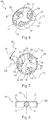
- FIG. 10 shows a perspective view of a spacer 10, the spacer 10 having an annular element 11 and three support elements 12. Furthermore, 12 bores 19 are provided in each of the three support elements. In particular, a bore 19 is provided in each support element 12.
- the hole 19 can be a through hole or a blind hole.
- the support elements 12 are attached to an inner surface 14 of the annular element 11. A radius can be provided as a transition between the respective support element 12 and the inner surface 14.
- the respective support elements 12 have an end face at an end 15 facing away from the inner face 14.
- Fig. 1 also shows a cylindrical outer surface 20 with a predetermined surface quality.
- the cylindrical outer surface 20 is designed to have an in Fig. 1 to keep outer conductor not shown at a distance.
- the end faces 16 provided on the end 15 facing away from the inner face 14 have a curved shape.
- a curved end face 16 is thus provided at the end 15 facing away from the inner surface 14 of the annular element 11.
- the support elements 12 are arranged at regular intervals along a circumferential direction 17 of the annular element 11.
- the support elements 12 are each equally spaced from one another along the circumferential direction 17.
- the angle between the radial directions 13 of the respective support elements 12 is preferably 120 ° in each case.
- the annular element 11 of the spacer 10 also has a center point which lies on an axis of rotation 18 of the annular element 11.
- Fig. 3 shows a sectional view through the spacer 10, in particular through the annular element 11.
- the annular element 11 can have a bevel on its edges, in particular on the edges delimiting the inner surface 14.
- the support element 12 can have an oval shape or a plan shape deviating from a circular shape in a plan on the inner surface 14.
- the end face 16 is in Fig. 3 shown in a top view.
- the axis of rotation 18 of the annular element 11 or of the spacer 10 is shown. The axis of rotation 18 runs through the center of the annular element 11.
- Fig. 4 shows a further example of a spacer 10, which has an annular element 11 and three support elements 12. There are in the support elements 12 in each case a bore 19, which can be designed, for example, as a through bore or as a blind bore, is provided.
- the outer surface 20 of the annular element 11 is again designed, one in Fig. 4 to keep outer conductor not shown at a distance.
- curved end faces are provided on an end 15 of the respective support element 12 facing away from the inner surface 14.
- the support elements 12 are arranged along the circumferential direction 17 at regular, but preferably at the same, intervals from one another.
- the angle between the radial directions 13 of the respective support elements 12 is 120 °, for example.
- the radial directions 13 of the respective support elements run through the center of the annular element 11, which lies on the axis of rotation 18 of the annular element or of the spacer 10.
- Fig. 6 shows the spacer 10, in which the annular element 11 is shown in section. It can be seen that the support element 12 has a plan area in the area of the inner surface 14 of the annular element 11 which deviates from a circular shape or is oval. It is also possible for the annular element 11 to have chamfers on the edges, in particular in the region of the inner surface 14.
- the embodiment shown of the spacer 10 has round support elements 12. Furthermore, material reinforcements are provided here in the area of the inclined bores 19 of the support elements 12.
- the material reinforcement has, for example, the shape of an attached spherical shape.
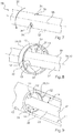
- Fig. 7 shows a rod-shaped inner conductor 30 with recesses 31 which are provided in a surface 37 of the rod-shaped inner conductor 30.
- the recesses 31 are provided in a row on the surface 37 of the rod-shaped inner conductor 30 along a circumferential direction 33 of the rod-shaped inner conductor. At least three recesses 31 can be provided on the surface 37 of the rod-shaped inner conductor 30.
- the recesses 31 are provided as blind bores, a base area 34 of the respective recesses 31 having a curved contour.
- the base area 34 of the recesses 31 has a single curved shape, the base area 34 being curved with respect to an axis of rotation which runs parallel to and preferably at a distance from an axis of rotation 35 of the rod-shaped inner conductor 30.
- the curved base surface 34 has a radius, the center of which does not lie on the axis of rotation 35 of the rod-shaped inner conductor 30.
- Fig. 8 shows a rod-shaped inner conductor 30 and a spacer 10 which is in engagement with the rod-shaped inner conductor 30.
- the spacer 10 has an annular element 11 with an inner surface 14.
- the support elements 12 protrude from the inner surface 14 in the radial direction of the annular element 11.
- Radial direction means that the support elements protrude in the direction of a center point of the annular element 11 from the inner surface 14 and thus the radial direction in the in Fig. 8
- the example shown extends through the axis of rotation 18 of the annular element 11, but also through the axis of rotation 35 of the rod-shaped inner conductor 30.
- the support elements 12 protrude into the recesses 31 which are provided in the surface 37 of the rod-shaped inner conductor 30.
- Fig. 9 shows an outer conductor 50 in a cut-away representation as well as the rod-shaped inner conductor 30 in which the spacer 10 engages.
- the Fig. 9 thus corresponds to in Fig. 8 illustrated case, where in Fig. 9 the outer conductor 50 of the coaxial measuring probe is also shown.
- the spacer 10 is designed in particular to keep or set a distance A between the rod-shaped inner conductor 30 and the outer conductor 50 essentially constant.
- An air gap can be provided between the outer surface 20 of the spacer 10 and the outer conductor 50, so that there is almost no play between the spacer 10 and the outer conductor 50. Forces can thus be effectively transmitted between the rod-shaped inner conductor 30 and the outer conductor 50 via the spacer 10.
- the distance A between the outer conductor 50 and the rod-shaped inner conductor 30 can be kept essentially constant, even if lateral forces act on the rod-shaped inner conductor 30 or the outer conductor 50, such as vibration loads.
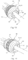
- Fig. 10 shows a tool 60 for mounting the spacer 10 on the rod-shaped inner conductor 30.
- the rod-shaped inner conductor 30 is shown in FIG Fig. 10 not shown.
- the tool 60 has an annular clamping device 62 with at least three pin elements 63.
- the tool 60 also has a rough surface 61 for actuating the tool 60.
- the pin elements 63 each have a longitudinal axis 64, the longitudinal axes 64 of the individual pin elements 63 being arranged inclined to one another.
- the pin elements 63 are movably supported in the annular clamping device 62, see above that the longitudinal axes 64 of the respective pin elements 63 always intersect at one point. However, it is also possible that the longitudinal axes 64 of the individual pin elements 63 do not intersect at one point.
- the spacer 10 is also provided on the tool 60. In particular, the spacer 10 is plugged or pushed onto the tool 60 in order to mount it on the rod-shaped inner conductor.
- Fig. 12 it can be seen that the pin elements 63 of the tool 60 are pushed through the bores 19 of the respective support elements 12. Furthermore, in Fig. 12 It can be seen that the pin elements 63 are arranged along a circumferential direction 65 of the tool 60 on an end face 66 of the annular clamping device 62 at regular intervals. For example, the pin elements 63 are also arranged at equal distances from one another along the circumferential direction 65 of the annular clamping device 62. The spacer 10 is pretensioned by pushing the pin elements 63 of the tool 60 through the bores 19 of the respective support elements 12. The tool 60 is displaced along the axis of rotation 18 of the annular element 11.
- the spacer 10 is therefore pushed onto the tool 60. It is possible for the tool 60 to preload the spacer 10 by moving the pin elements 63 in the directions marked by arrows 67.
- the pin elements 63 can be designed to hold the spacer 10 for mounting on the in Fig. 12 bar-shaped inner conductor 30, not shown, by reducing an angle between the longitudinal axes 64 of at least two pin elements 63, but preferably all three pin elements 63.
- the spacer 10 is pretensioned by simply pushing the pin elements 63 through the bores 19 of the support elements 12.
- the deformation of the annular element 11 of the spacer 10 is shown in FIG Fig. 12 clearly visible.
- the spacer 10 or the annular element 11 is expanded at the points at which the pin elements 63 are located.
- Fig. 13 shows the positioning of the spacer 10 on the rod-shaped inner conductor 30, the spacer 10 being pretensioned with the aid of the pin elements 63 of the tool 60.
- the spacer 10 can be prestressed by the pin elements 63 in such a way that the curved end faces 16 of the support elements 12 can be guided along or on the surface 37 of the rod-shaped inner conductor 30. In other words, the spacer 10 is pushed over the surface 37 of the rod-shaped inner conductor 30 to the corresponding position on the rod-shaped inner conductor 30.
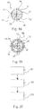
- Fig. 15 shows a side view of a rod-shaped inner conductor 30.
- the rod-shaped inner conductor 30 has a fastening unit 80, for example a screw connection, at a first end of the rod-shaped inner conductor 30, via which the rod-shaped inner conductor 30 is fastened to a measuring device.
- the outer conductor 50 can also be attached to this measuring device, so that the rod-shaped inner conductor 30 is only connected to the outer conductor 50 via the measuring device, since a small air gap can be provided between the spacer 10 and the outer conductor 50.
- the rod-shaped inner conductor 30 also has a first row 32 with at least three recesses 31 along one
- the spacer 10 is in Fig. 15 not shown.
- only one recess 31 of the first row 32 is shown completely.
- the rod-shaped inner conductor 30 also has a second row 36 with at least three recesses 31 along a circumferential direction 33 of the rod-shaped inner conductor 30 for receiving a support element 12 of a further not in each case Fig. 15 spacer 10 shown.
- only one recess 31 of the second row 36 of recesses 31 is shown completely.
- the second row 36 with at least three recesses 31 is arranged in the region of a second end of the rod-shaped inner conductor 30.
- the first row 32 with the at least three recesses 31 is arranged approximately centrally between the fastening unit 80 and the second row 36 with at least three recesses 31 on the rod-shaped inner conductor 30.
- Fig. 16 shows the rod-shaped inner conductor 30 and the outer conductor 50, the outer conductor 50 being held at a distance A from the rod-shaped inner conductor 30 by precisely two spacers 10.
- the spacers 10 are designed to hold the rod-shaped inner conductor 30 essentially coaxially to the outer conductor 50, or to keep it at a distance.
- the axis of rotation 18 of the spacer 10 lies on the axis of rotation 35 of the rod-shaped inner conductor 30 when the level measuring probe is in an assembled state and the rod-shaped inner conductor 30 and the outer conductor 50 are aligned coaxially to one another.
- Fig. 17 shows a side view of a level measuring probe 70 with an outer conductor 50.
- Several bores can be provided in the outer conductor 50, which are offset from one another.
- the rod-shaped inner conductor 30 and the spacers 10 are covered by the outer conductor 50.
- Fig. 18 shows a sectional view of a rod-shaped inner conductor 30, the rod-shaped inner conductor 30 having recesses 31, in particular depressions, in the surface 37 of the rod-shaped inner conductor 30.
- the recesses 31 each have a base area 34, each base area 34 having a radius whose center point does not lie on the axis of rotation 35 of the rod-shaped inner conductor 30.
- the base surfaces 34 of the recesses 31 are designed to accommodate the curved end surfaces 16 of the support elements 12 of the spacer 10.
- the spacer 10 is in Fig. 18 not shown.
- Fig. 19 shows a sectional view through an outer conductor 50 and a rod-shaped inner conductor 30 of a coaxial fill level measuring probe 70 and a plan view of a spacer 10.
- the support elements 12 of the spacer 10 engage in the Fig. 19 Recesses 31, not shown, on the surface 37 of the rod-shaped inner conductor 30 in order to align the outer conductor 50 coaxially with the rod-shaped inner conductor 30 or to keep it at a distance.
- the axis of rotation 18 of the spacer 10 lies on the axis of rotation 35 of the rod-shaped inner conductor 30.
- Fig. 20 shows a flowchart for an assembly method for assembling a spacer 10 on a rod-shaped inner conductor 30.
- the spacer 10 is pretensioned so that the support elements 12 of the annular element 11 are positioned above a surface 37 of the rod-shaped inner conductor 30 along an axis of rotation 35 of the rod-shaped inner conductor 30 can be guided.
- the spacer 10 is positioned in relation to the rod-shaped inner conductor 30.
- the spacer 10 is guided over the rod-shaped inner conductor 30 or pushed onto the rod-shaped inner conductor 30 and positioned over the recesses 31 of the rod-shaped inner conductor 30 .
- the spacer 10 is relaxed so that the support elements 12 of the annular element 11 engage in corresponding recesses 31 of the rod-shaped inner conductor 30.
Landscapes
- Physics & Mathematics (AREA)
- General Physics & Mathematics (AREA)
- Electromagnetism (AREA)
- Fluid Mechanics (AREA)
- Thermal Sciences (AREA)
- Engineering & Computer Science (AREA)
- Mechanical Engineering (AREA)
- Measuring Leads Or Probes (AREA)
Description
Die vorliegende Erfindung betrifft einen Abstandhalter zum Halten eines Abstandes zwischen einem stabförmigen Innenleiter und einem Außenleiter einer Füllstandmesssonde. Die Erfindung betrifft ferner einen stabförmigen Innenleiter einer Messsonde, eine Messsonde zur Ermittlung eines Füllstandes eines in einem Behälter befindlichen Mediums, sowie ein Montageverfahren zur Montage eines Abstandhalters auf einem stabförmigen Innenleiter.The present invention relates to a spacer for maintaining a distance between a rod-shaped inner conductor and an outer conductor of a level measuring probe. The invention also relates to a rod-shaped inner conductor of a measuring probe, a measuring probe for determining a fill level of a medium located in a container, and an assembly method for assembling a spacer on a rod-shaped inner conductor.
Die Zeitbereichsreflektometrie, welche im Englischen auch bekannt ist unter dem Namen Time Domain Reflectometry (TDR), wird zur Ermittlung und Analyse von Lauflängen und Reflexionscharakteristika von elektromagnetischen Wellen und Signalen verwendet.Time domain reflectometry, which is also known as Time Domain Reflectometry (TDR), is used to determine and analyze run lengths and reflection characteristics of electromagnetic waves and signals.
Bei einem auf TDR-basierenden Füllstandmessgerät wird von der Elektronik des Sensors ein elektromagnetischer Impuls erzeugt, in einen Leiter, welcher beispielsweise auch als Messsonde bezeichnet wird, eingekoppelt und entlang dieser Sonde geführt. Dabei kommen beispielsweise Koaxialmesssonden zum Einsatz, bei denen ein stabförmiger Innenleiter CGS:PSUIn a TDR-based level measuring device, an electromagnetic pulse is generated by the electronics of the sensor, coupled into a conductor, which is also referred to as a measuring probe, and guided along this probe. For example, coaxial measuring probes are used in which a rod-shaped inner conductor CGS: PSU
innerhalb eines röhrenförmigen Außenleiters angeordnet ist. Nachdem der elektromagnetische Impuls in die Messsonde eingekoppelt wurde, wird dieser nun an der Oberfläche des zu messenden Mediums reflektiert und läuft entlang der Messsonde wieder zurück zu einer Elektronik, welche dann aus der Zeitdifferenz zwischen dem ausgesandten und dem empfangenen Impuls den Füllstand berechnet.is arranged within a tubular outer conductor. After the electromagnetic pulse has been coupled into the measuring probe, it is now reflected on the surface of the medium to be measured and runs back along the measuring probe to an electronics unit, which then calculates the level from the time difference between the transmitted and received pulse.
Eine solche Messsonde kann Vibrationen bzw. äußeren Erschütterungen ausgesetzt sein, so dass dadurch Ungenauigkeiten bei der Messung entstehen können. Insbesondere kann es zu einer ungewollten Relativbewegung zwischen dem röhrenförmigen Außenleiter und den sich darin befindenden stabförmigen Innenleiter der Messsonde kommen, so dass die Qualität des Messsignals beeinträchtigt wird.Such a measuring probe can be exposed to vibrations or external shocks, so that this can result in inaccuracies in the measurement. In particular, there can be an undesired relative movement between the tubular outer conductor and the rod-shaped inner conductor of the measuring probe located therein, so that the quality of the measuring signal is impaired.
Die
Die
Es ist eine Aufgabe der Erfindung, eine verbesserte Koaxialmesssonde zur Füllstandmessung bereitzustellen.It is an object of the invention to provide an improved coaxial measuring probe for level measurement.
Diese Aufgabe wird durch die Gegenstände der unabhängigen Ansprüche gelöst. Beispielhafte Ausführungsformen ergeben sich aus den abhängigen Ansprüchen und der nachfolgenden Beschreibung.This object is achieved by the subjects of the independent claims. Exemplary embodiments emerge from the dependent claims and the following description.
Gemäß einem Aspekt der Erfindung ist ein Abstandhalter zum Halten eines Abstandes zwischen einem stabförmigen Innenleiter und einem Außenleiter einer Füllstandmesssonde angegeben. Der Abstandhalter weist ein ringförmiges Element sowie zumindest drei Stützelemente auf, welche jeweils in einer radialen Richtung aus einer Innenfläche des ringförmigen Elementes herausragen. Dabei weist jedes der drei Stützelemente an einem der Innenfläche abgewandten Ende eine gebogene Stirnfläche auf. Das der Innenfläche abgewandte Ende ist zum Eingriff in eine Ausnehmung des stabförmigen Innenleiters ausgeführt.According to one aspect of the invention, a spacer for maintaining a distance between a rod-shaped inner conductor and an outer conductor of a level measuring probe is specified. The spacer has an annular element and at least three support elements which each protrude in a radial direction from an inner surface of the annular element. Each of the three support elements has a curved end face at an end facing away from the inner face. The end facing away from the inner surface is designed to engage in a recess in the rod-shaped inner conductor.
Mit einem solchen Abstandhalter ist es möglich, eine stabile Abstützung des stabförmigen Innenleiters bzw. Innenstabes in einer koaxialen Messsonde, welche im Folgenden auch als Füllstandmesssonde oder einfach als Messsonde bezeichnet wird, bereitzustellen. Insbesondere kann die Eignung solcher Messsonden in Systemen mit Vibrationsbelastung verbessert werden. Beispielsweise können bei der Füllstandmessung Vibrationsbelastungen bzw. äußere Erschütterungen auftreten, welche das Messergebnis beeinträchtigen können.With such a spacer it is possible to provide stable support for the rod-shaped inner conductor or inner rod in a coaxial measuring probe, which is also referred to below as a fill level measuring probe or simply as a measuring probe. In particular, the suitability of such measuring probes can be improved in systems with vibration loads. For example, when measuring the level, vibration loads or external shocks can occur, which can impair the measurement result.
Durch den Abstandhalter ist es möglich, auch bei Vibrationsbelastungen die Relativbewegung zwischen dem stabförmigen Innenleiter und dem Außenleiter der Messsonde zu verringern. Gleichzeitig können elektrische Abweichungen des Messsignals pro Abstandhalter gering gehalten werden. Beispielsweise können HF-Störsignale, das heißt hochfrequente Störsignale, gegenüber herkömmlichen Verbindungsmitteln zur Verbindung des stabförmigen Innenleiters und des Außenleiters reduziert werden.The spacer makes it possible to reduce the relative movement between the rod-shaped inner conductor and the outer conductor of the measuring probe even in the event of vibration loads. At the same time, electrical deviations in the measurement signal per spacer can be kept low. For example, HF interference signals, that is to say high-frequency interference signals, can be reduced compared to conventional connecting means for connecting the rod-shaped inner conductor and the outer conductor.
Aufgrund des einfachen Aufbaus kann ferner ein gutes Ablaufverhalten von dem zu messenden Medium erreicht werden und der Verschmutzungsgrad der Messsonde kann gering gehalten werden, da wenige Flächen für Ablagerungen innerhalb der Messsonde durch den Abstandhalter eingebracht werden. Nicht zuletzt kann durch den Abstandhalter ein zuverlässiger Schutz gegen das Herausfallen des Abstandhalters aus der Messsonde gewährleistet werden.Due to the simple structure, good drainage behavior of the medium to be measured can also be achieved and the degree of contamination of the measuring probe can be kept low, since the spacer introduces few areas for deposits within the measuring probe. Last but not least, the spacer can guarantee reliable protection against the spacer falling out of the measuring probe.
Das ringförmige Element weist beispielsweise die Form eines röhrenförmigen Segments auf. Das ringförmige Element kann ein dünnwandiges röhrenförmiges Segment sein, beispielsweise in Form eines dünnwandigen Zylinders. Insbesondere kann das ringförmige Element die Form eines Abschnittes eines Zylindermantels aufweisen. Dabei weist das ringförmige Element eine zylinderförmige Innenfläche sowie eine zylinderförmige Außenfläche auf. Aus der zylinderförmigen Innenfläche ragen die drei Stützelemente in radialer Richtung zu einem Mittelpunkt des ringförmigen Elements heraus. Dabei können die jeweiligen Stützelemente entlang einer Umfangsrichtung des ringförmigen Elements in regelmäßigen Abständen zueinander auf der Innenfläche angeordnet sein. Beispielsweise beträgt der Winkel zwischen jedem Stützelement, insbesondere zwischen den radialen Richtungen der Stützelemente, bezüglich der Umfangsrichtung des ringförmigen Elements 120°.The annular element has, for example, the shape of a tubular segment. The annular element can be a thin-walled tubular segment, for example in the form of a thin-walled cylinder. In particular, the ring-shaped element can have the shape of a section of a cylinder jacket. The ring-shaped element has a cylindrical inner surface and a cylindrical outer surface. The three support elements protrude from the cylindrical inner surface in the radial direction to a center point of the annular element. The respective support elements can be arranged along a circumferential direction of the annular element at regular intervals from one another on the inner surface. For example, the angle between each support element, in particular between the radial directions of the support elements, with respect to the circumferential direction of the annular element is 120 °.
Die drei Stützelemente weisen jeweils ein von der Innenfläche abgewandtes Ende auf. An diesem der Innenfläche abgewandten Ende befindet sich die gebogene Stirnfläche, welche beispielsweise eine einfach gekrümmte Fläche ist. Einfach gekrümmte Fläche bedeutet im Sinne der vorliegenden Erfindung, dass die Fläche nur entlang einer Richtung gebogen ist und entlang einer weiteren Richtung keine Krümmung aufweist. Somit kann die gebogene Stirnfläche beispielsweise ein Segment einer Zylindermantelfläche sein.The three support elements each have an end facing away from the inner surface. At this end facing away from the inner surface there is the curved end face, which is, for example, a simply curved surface. In the context of the present invention, a single curved surface means that the surface is curved only in one direction and has no curvature in a further direction. Thus, the curved end face can, for example, be a segment of a cylinder jacket surface.
Jedes der drei Stützelemente kann ferner ein der Innenfläche zugewandtes Ende aufweisen, an welchem das jeweilige Stützelement an der Innenfläche des ringförmigen Elements befestigt ist. Zwischen diesem der Innenfläche zugewandten Ende und der Innenfläche selbst kann ein Radius als Übergang von der Innenfläche zu dem jeweiligen Stützelement vorgesehen sein. Der Abstandhalter kann ein flexibles bzw. elastisches Material aufweisen, so dass der Abstandhalter mithilfe eines Montagewerkzeuges auf dem stabförmigen Innenleiter positioniert werden kann und anschließend der Außenleiter über dem Abstandhalter aufgesetzt werden kann. Um den Abstandhalter auf dem stabförmigen Innenleiter zu fixieren, ist das der Innenfläche abgewandte Ende der Stützelemente zum Eingriff in eine Ausnehmung des stabförmigen Innenleiters ausgeführt.Each of the three support elements can furthermore have an end facing the inner surface, at which the respective support element is fastened to the inner surface of the annular element. Between this end facing the inner surface and the inner surface itself, a radius can be provided as a transition from the inner surface to the respective support element. The spacer can have a flexible or elastic material, so that the spacer can be positioned on the rod-shaped inner conductor with the aid of an assembly tool and then the outer conductor can be placed over the spacer. In order to fix the spacer on the rod-shaped inner conductor, the end of the support elements facing away from the inner surface is designed to engage in a recess of the rod-shaped inner conductor.
Der stabförmige Innenleiter weist dazu ebenfalls drei Ausnehmungen auf, welche mit dem jeweiligen Stützelement des Abstandhalters korrespondieren, so dass das der Innenfläche abgewandte Ende des jeweiligen Stützelements in die korrespondierende Ausnehmung des stabförmigen Innenleiters eingreifen kann. Für den Fall, dass das der Innenfläche abgewandte Ende des Stützelements in die Ausnehmung des stabförmigen Innenleiters eingreift, unterscheidet sich der Radius der gebogenen Stirnfläche des der Innenfläche abgewandten Endes von einem Radius einer Oberfläche des stabförmigen Innenleiters. Jedoch kann der Radius der gebogenen Stirnfläche mit dem Radius der Oberfläche des stabförmigen Innenleiters übereinstimmen während der Abstandhalter auf dem stabförmigen Innenleiter positioniert wird. Dieser Aspekt wird in Folgenden und in der Figurenbeschreibung noch genauer erläutert werden.The rod-shaped inner conductor also has three recesses for this purpose, which correspond to the respective support element of the spacer, so that the end of the respective support element facing away from the inner surface can engage in the corresponding recess of the rod-shaped inner conductor. In the event that the end of the support element facing away from the inner surface engages in the recess of the rod-shaped inner conductor, the radius of the curved end face of the end facing away from the inner surface differs from a radius of a surface of the rod-shaped inner conductor. However, the radius of the curved end face can match the radius of the surface of the rod-shaped inner conductor while the spacer is positioned on the rod-shaped inner conductor. This aspect will be explained in more detail below and in the description of the figures.
Gemäß einer Ausführungsform der Erfindung verjüngen sich die zumindest drei Stützelemente in radialer Richtung. Die radiale Richtung stellt dabei zum Beispiel eine Mittelachse des jeweiligen Stützelementes dar.According to one embodiment of the invention, the at least three support elements taper in the radial direction. The radial direction represents, for example, a central axis of the respective support element.
Die radiale Richtung ist dabei eine radiale Richtung in Bezug zum ringförmigen Element, das heißt, die radiale Richtung verläuft durch den Mittelpunkt des ringförmigen Elements. Durch die Verjüngung ist die Querschnittsfläche des Stützelements senkrecht zur radialen Richtung an einem der Innenfläche des ringförmigen Elements zugewandten Ende größer als eine Querschnittsfläche des Stützelements an dem der Innenfläche abgewandten Ende des Stützelements. Auch dieser Aspekt wird in der Figurenbeschreibung noch genauer erläutert werden.The radial direction is a radial direction in relation to the annular element, that is, the radial direction runs through the center of the annular element. As a result of the tapering, the cross-sectional area of the support element perpendicular to the radial direction at an end facing the inner surface of the annular element is larger than a cross-sectional area of the support element at the end of the support element remote from the inner surface. This aspect will also be explained in more detail in the description of the figures.
Die zumindest drei Stützelemente können eine kreisförmige oder eine ovale Querschnittsfläche aufweisen. Dabei kann sich die Form der Querschnittsfläche des jeweiligen Stützelements in radialer Richtung verändern. Beispielsweise kann die Querschnittsfläche an einem der Innenfläche des ringförmigen Elements zugewandten Ende eine ovale Form aufweisen, wobei die Querschnittsfläche des der Innenfläche abgewandten Endes eine Kreisform aufweist.The at least three support elements can have a circular or oval cross-sectional area. The shape of the cross-sectional area of the respective support element can change in the radial direction. For example, the cross-sectional area at an end facing the inner surface of the annular element can have an oval shape, the cross-sectional area of the end facing away from the inner surface having a circular shape.
Gemäß einer weiteren Ausführungsform der Erfindung sind die zumindest drei Stützelemente in regelmäßigen Abständen entlang einer Umfangsrichtung des ringförmigen Elements angeordnet.According to a further embodiment of the invention, the at least three support elements are arranged at regular intervals along a circumferential direction of the annular element.
Dabei bezeichnet die Umfangsrichtung diejenige Richtung, die sich entlang der zylinderförmigen Innenfläche oder der zylinderförmigen Außenfläche des ringförmigen Elements erstreckt. Entlang der Umfangsrichtung können die Stützelemente jeweils in gleichen Abständen zueinander auf der Innenfläche des ringförmigen Elements angeordnet sein. Dabei kann ein Winkel von 120° zwischen den jeweiligen Stützelementen vorgesehen sein. Durch das Vorsehen von genau drei Stützelementen kann bereits ein effektiver Abstandhalter für den Betrieb einer Koaxialmesssonde bereitgestellt werden.The circumferential direction denotes that direction which extends along the cylindrical inner surface or the cylindrical outer surface of the annular element. Along the circumferential direction, the support elements can each be arranged at equal distances from one another on the inner surface of the annular element. An angle of 120 ° can be provided between the respective support elements. By providing exactly three support elements, an effective spacer can already be provided for the operation of a coaxial measuring probe.
Für den Fall, dass mehr als drei Stützelemente auf der Innenfläche des ringförmigen Elements vorgesehen sind, kann ein entsprechend kleinerer Winkel zwischen den einzelnen Stützelementen vorgesehen sein, wobei die Stützelemente wiederum in gleichen Abständen entlang der Umfangsrichtung auf der Innenfläche des ringförmigen Elements angeordnet sein können. Somit kann eine gleichmäßige Kraftübertragung zwischen dem stabförmigen Innenleiter und dem Außenleiter der Messsonde im Falle einer Vibrationsbelastung erreicht werden.In the event that more than three support elements are provided on the inner surface of the annular element, a correspondingly smaller angle can be provided between the individual support elements, the support elements in turn being arranged at equal intervals along the circumferential direction on the inner surface of the annular element. In this way, a uniform force transmission between the rod-shaped inner conductor and the outer conductor of the measuring probe can be achieved in the event of a vibration load.
Durch das Vorsehen von zumindest drei Stützelementen kann eine ausreichende Stabilität bzw. Widerstandsfähigkeit gegen Vibrationsbelastungen und zugleich eine einfache Montage des Abstandhalters auf dem stabförmigen Innenleiter gewährleistet werden. Insbesondere können die Stützelemente während der Montage des Abstandhalters auf dem stabförmigen Innenleiter an einer Oberfläche des stabförmigen Innenleiters vorbeigeführt werden. Dies wird im weiteren Verlauf der Beschreibung noch genauer erläutert werden.By providing at least three support elements, sufficient stability or resistance to vibration loads and, at the same time, simple assembly of the spacer on the rod-shaped inner conductor can be ensured. In particular, the support elements can be guided past a surface of the rod-shaped inner conductor during the assembly of the spacer on the rod-shaped inner conductor. This will be explained in more detail in the further course of the description.
Gemäß einer weiteren Ausführungsform der Erfindung weist die gebogene Stirnfläche des jeweiligen Stützelementes einen Radius auf, dessen Mittelpunkt nicht auf einer Rotationsachse des ringförmigen Elements bzw. des Abstandhalters liegt.According to a further embodiment of the invention, the curved end face of the respective support element has a radius, the center of which does not lie on an axis of rotation of the annular element or of the spacer.
Insbesondere kann der Radius der gebogenen Stirnfläche so gewählt sein, dass bei der Verformung des Abstandhalters bzw. des ringförmigen Elements während der Montage eine optimale Führbarkeit der gebogenen Stirnflächen der Stützelemente über einer Oberfläche des stabförmigen Innenleiters gewährleistet wird. Bei einer solchen Verformung des Abstandhalters während der Montage kann eine Verschiebung der gebogenen Stirnflächen der Stützelemente, beispielsweise von jeweils 0,3 mm, in Bezug auf den Mittelpunkt des ringförmigen Elements erfolgen. Die gebogenen Stirnflächen werden dabei vom Mittelpunkt wegbewegt. Die gebogenen Stirnflächen bzw. die Auflageflächen der Stützelemente sind demnach so ausgelegt, dass der Verformungsweg zum Aufschieben auf den stabförmigen Innenleiter während der Montage möglichst gering ist, um somit eine Schädigung des Abstandhalters beim Aufdehnen zu vermeiden. In diesem Fall entspricht der Radius der gebogenen Stirnfläche dem Radius der Oberfläche des stabförmigen Innenleiters. Mit anderen Worten entspricht der Radius der gebogenen Stirnfläche während der Verformung, das heißt während der Montage des Abstandhalters auf dem stabförmigen Innenleiter, dem Radius der Oberfläche des stabförmigen Innenleiters, jedoch liegt der Mittelpunkt des Radius der gebogenen Stirnfläche vor oder nach der Montage, das heißt im entspannten Zustand des Abstandhalters, nicht auf der Rotationsachse des ringförmigen Elements. Somit ist die gebogene Stirnfläche dazu ausgeführt, eine optimale Führung des Abstandhalters über der Oberfläche des stabförmigen Elements während der Montage zu gewährleisten.In particular, the radius of the curved end face can be chosen so that when the spacer or the annular element is deformed during assembly, optimal guidability of the curved end faces of the support elements over a surface of the rod-shaped inner conductor is ensured. With such a deformation of the spacer during assembly, the curved end faces of the support elements can be shifted, for example by 0.3 mm each, with respect to the center point of the annular element. The curved end faces are moved away from the center. The curved end faces or the bearing surfaces of the support elements are accordingly designed in such a way that the deformation path for pushing onto the rod-shaped Inner conductor is as small as possible during assembly in order to avoid damage to the spacer when expanding. In this case, the radius of the curved end face corresponds to the radius of the surface of the rod-shaped inner conductor. In other words, the radius of the curved end face during the deformation, i.e. during the assembly of the spacer on the rod-shaped inner conductor, corresponds to the radius of the surface of the rod-shaped inner conductor, but the center point of the radius of the curved end face lies before or after assembly, that is in the relaxed state of the spacer, not on the axis of rotation of the annular element. Thus, the curved end face is designed to ensure optimal guidance of the spacer over the surface of the rod-shaped element during assembly.
Gemäß der Erfindung weisen die zumindest drei Stützelemente jeweils eine Bohrung auf. Die Bohrungsachsen der durch die Stützelemente verlaufenden Bohrungen sind jeweils gegenüber einer Rotationsachse des ringförmigen Elements geneigt angeordnet.According to the invention, the at least three support elements each have a bore. The bore axes of the bores running through the support elements are each arranged inclined with respect to an axis of rotation of the annular element.
Die Rotationsachse des ringförmigen Elements verläuft dabei wiederum durch den Mittelpunkt des ringförmigen Elements. Es sind somit schräge Bohrungen in den jeweiligen Stützelementen vorgesehen, wobei die Bohrungen dazu ausgeführt sind, ein Stiftelement eines Montagewerkzeugs aufzunehmen. Die Bohrungsachsen der jeweiligen Stützelemente können gegenüber der Rotationsachse des ringförmigen Elements um etwa 0° bis 20°, vorzugsweise um etwa 0° bis 10° und insbesondere um etwa 2,5° geneigt angeordnet sein. Die Bohrungen der jeweiligen Stützelemente können durch eine Mittelachse der Stützelemente verlaufen, welche beispielsweise auf der radialen Richtung der jeweiligen Stützelemente liegt.The axis of rotation of the ring-shaped element in turn runs through the center of the ring-shaped element. Inclined bores are thus provided in the respective support elements, the bores being designed to receive a pin element of an assembly tool. The bore axes of the respective support elements can be inclined by about 0 ° to 20 °, preferably by about 0 ° to 10 ° and in particular by about 2.5 °, with respect to the axis of rotation of the annular element. The bores of the respective support elements can run through a central axis of the support elements which, for example, lies in the radial direction of the respective support elements.
Gemäß einer weiteren Ausführungsform der Erfindung schneiden sich die jeweiligen Bohrungsachsen der durch die Stützelemente verlaufenden Bohrungen in einem gemeinsamen Punkt, welcher auf der Rotationsachse des ringförmigen Elements liegt.According to a further embodiment of the invention, the respective bore axes of the bores running through the support elements intersect at a common point which lies on the axis of rotation of the annular element.
Mit anderen Worten besitzen sämtliche Bohrungsachsen der Stützelemente die gleiche Neigung gegenüber der Rotationsachse des ringförmigen Elements. Diese Neigung wird durch die Ausrichtung von den durch die Bohrungen aufzunehmenden Stiftelementen eines Montagewerkzeugs vorgegeben. Durch diese Neigung ist es möglich, den Abstandhalter durch die aufzunehmenden Stiftelemente des Montagewerkzeugs aufzudehnen bzw. vorzuspannen, um somit den Abstandhalter auf dem stabförmigen Innenleiter zu montieren.In other words, all the bore axes of the support elements have the same inclination with respect to the axis of rotation of the annular element. This inclination is predetermined by the alignment of the pin elements of an assembly tool to be received through the bores. As a result of this inclination, it is possible to expand or pretension the spacer by the pin elements of the assembly tool to be received, in order thus to mount the spacer on the rod-shaped inner conductor.
Gemäß einer weiteren Ausführungsform der Erfindung weist das ringförmige Element eine zylinderförmige Außenfläche auf.According to a further embodiment of the invention, the annular element has a cylindrical outer surface.
Gemäß einer weiteren Ausführungsform der Erfindung ist der Abstandhalter aus einem Kunststoffmaterial gefertigt.According to a further embodiment of the invention, the spacer is made from a plastic material.
Insbesondere ist es möglich, dass der Abstandhalter aus Polyetheretherketon (PEEK) gefertigt ist. Durch ein solches Material kann eine hohe Festigkeit über einen großen Temperaturbereich gewährleistet werden, wobei ein solches Material ferner chemisch beständig ist. Dies ist insbesondere von Vorteil, da der Abstandhalter bei der Messung des Füllstandes mit dem jeweiligen zu messenden Medium in Kontakt treten kann.In particular, it is possible for the spacer to be made from polyetheretherketone (PEEK). Such a material can ensure high strength over a wide temperature range, and such a material is also chemically resistant. This is particularly advantageous because the spacer can come into contact with the respective medium to be measured when measuring the fill level.
Gemäß einem Aspekt der Erfindung ist ein stabförmiger Innenleiter einer Messsonde angegeben. Der stabförmige Innenleiter weist eine erste Reihe mit zumindest drei Ausnehmungen entlang einer Umfangsrichtung des stabförmigen Innenleiters zur Aufnahme jeweils eines Stützelementes eines Abstandhalters, insbesondere des zuvor beschriebenen Abstandhalters, auf. Die Ausnehmungen weisen jeweils eine gebogene Grundfläche mit einem Radius auf, dessen Mittelpunkt nicht auf einer Rotationsachse des stabförmigen Innenleiters liegt. Die Ausnehmungen sind als Sacklochbohrungen vorgesehen.According to one aspect of the invention, a rod-shaped inner conductor of a measuring probe is specified. The rod-shaped inner conductor has a first row with at least three recesses along a circumferential direction of the rod-shaped inner conductor for receiving a support element of a spacer, in particular the spacer described above. The recesses each have a curved base area with a radius, the center of which does not lie on an axis of rotation of the rod-shaped inner conductor. The recesses are provided as blind holes.
Es ist möglich, auf diesem stabförmigen Innenleiter den zuvor beschriebenen Abstandhalter aufzusetzen, so dass der Abstandhalter den stabförmigen Innenleiter sowie den Außenleiter der Füllstandmesssonde in einer im Wesentlichen koaxialen Ausrichtung zueinander hält. Hierfür können an einer Oberfläche des stabförmigen Innenleiters die Ausnehmungen in Form von Vertiefungen in der Oberfläche des stabförmigen Innenleiters vorgesehen sein. Die Ausnehmungen können in Form von Bohrungen in dem stabförmigen Innenleiter vorgesehen sein, wobei die Grundfläche der Ausnehmungen eine einfach gebogene Form annimmt. Einfach gebogene Grundfläche bedeutet auch hier, dass die Grundfläche entlang einer Richtung, beispielsweise entlang einer Umfangsrichtung des stabförmigen Innenleiters gebogen ist und entlang einer weiteren Richtung, welche beispielsweise parallel zur Rotationsachse des stabförmigen Innenleiters ist, keine Krümmung aufweist.It is possible to place the previously described spacer on this rod-shaped inner conductor, so that the spacer holds the rod-shaped inner conductor and the outer conductor of the level measuring probe in an essentially coaxial alignment with one another. For this purpose, the recesses in the form of depressions in the surface of the rod-shaped inner conductor can be provided on a surface of the rod-shaped inner conductor. The recesses can be provided in the form of bores in the rod-shaped inner conductor, the base of the recesses assuming a simply curved shape. Here, too, simply curved base area means that the base area is bent along one direction, for example along a circumferential direction of the rod-shaped inner conductor, and has no curvature along a further direction, which is, for example, parallel to the axis of rotation of the rod-shaped inner conductor.
Die gebogene Grundfläche der Ausnehmung weist dieselbe Krümmung auf wie die gebogene Stirnfläche an dem der Innenfläche abgewandten Ende des Stützelements des Abstandhalters. Somit kann während des Eingriffs das der Innenfläche abgewandte Ende, insbesondere die gebogene Stirnfläche des Stützelements des Abstandhalters auf der gebogenen Grundfläche des stabförmigen Innenleiters aufliegen. Insbesondere sind die Vertiefungen, das heißt die Ausnehmungen, in dem stabförmigen Innenleiter zur optimalen Auflage mit demselben Radius eingeformt wie die gebogene Stirnfläche der Stützelemente des Abstandhalters.The curved base of the recess has the same curvature as the curved end face on the end of the support element of the spacer facing away from the inner surface. Thus, during the engagement, the end facing away from the inner surface, in particular the curved end face of the support element of the spacer, can rest on the curved base surface of the rod-shaped inner conductor. In particular, the depressions, that is to say the recesses, are formed in the rod-shaped inner conductor for optimal support with the same radius as the curved end face of the support elements of the spacer.
Gemäß einer Ausführungsform der Erfindung ist die gebogene Grundfläche der Ausnehmung einfach gekrümmt. Eine Rotationsachse der einfach gekrümmten Grundfläche der Ausnehmung und die Rotationsachse des stabförmigen Innenleiters sind dabei zueinander beabstandet.According to one embodiment of the invention, the curved base of the recess is simply curved. An axis of rotation of the simply curved base surface of the recess and the axis of rotation of the rod-shaped inner conductor are spaced apart from one another.
Die gebogene Grundfläche der Ausnehmungen ist dabei an die gebogene Stirnfläche der Stützelemente des Abstandhalters angepasst. Insbesondere ist es möglich, dass die gebogeneThe curved base of the recesses is adapted to the curved end face of the support elements of the spacer. In particular, it is possible that the curved
Stirnfläche der Stützelemente des Abstandhalters während des Eingriffs in die Ausnehmungen des stabförmigen Innenleiters auf den gebogenen Grundflächen der Ausnehmungen des stabförmigen Innenleiters aufliegen. Ferner haben die gebogenen Grundflächen der jeweiligen Ausnehmung und der stabförmige Innenleiter Rotationsachsen, die zueinander beabstandet sind. Ferner sind auch die Rotationsachsen der gebogenen Grundflächen einer jeden Ausnehmung zueinander beabstandet. Mit anderen Worten hat jede gekrümmte Grundfläche einen Radius, dessen Mittelpunkt auf einer eigenen Rotationsachse liegt, wobei die Rotationsachsen der gekrümmten Grundflächen jeder Ausnehmung zueinander beabstandet sind.The end face of the support elements of the spacer rest on the curved base surfaces of the recesses of the rod-shaped inner conductor during the engagement in the recesses of the rod-shaped inner conductor. Furthermore, the curved base surfaces of the respective recess and the rod-shaped inner conductor have axes of rotation that are spaced apart from one another. Furthermore, the axes of rotation of the curved base surfaces of each recess are also spaced from one another. In other words, each curved base surface has a radius, the center of which lies on its own axis of rotation, the axes of rotation of the curved base surfaces of each recess being spaced from one another.
Gemäß einer weiteren Ausführungsform der Erfindung weist der stabförmige Innenleiter ferner eine zweite Reihe mit zumindest drei Ausnehmungen entlang einer Umfangsrichtung des stabförmigen Innenleiters zur Aufnahme jeweils eines Stützelements eines Abstandhalters, insbesondere des zuvor beschriebenen Abstandhalters, auf. Dabei sind die zweite Reihe mit den zumindest drei Ausnehmungen und die erste Reihe mit den zumindest drei Ausnehmungen entlang der Rotationsachse des stabförmigen Innenleiters voneinander beabstandet. Weitere Reihen mit zumindest drei Ausnehmungen im stabförmigen Innenleiter sind ebenso möglich.According to a further embodiment of the invention, the rod-shaped inner conductor also has a second row with at least three recesses along a circumferential direction of the rod-shaped inner conductor for receiving a support element of a spacer, in particular the spacer described above. The second row with the at least three recesses and the first row with the at least three recesses are spaced apart from one another along the axis of rotation of the rod-shaped inner conductor. Further rows with at least three recesses in the rod-shaped inner conductor are also possible.
Somit können mehrere Abstandhalter an dem stabförmigen Innenleiter vorgesehen werden. Beispielsweise werden exakt zwei Abstandhalter zwischen dem stabförmigen Innenleiter und dem Außenleiter vorgesehen, um die Vibrationseigenschaften der Messsonde zu verbessern.Several spacers can thus be provided on the rod-shaped inner conductor. For example, exactly two spacers are provided between the rod-shaped inner conductor and the outer conductor in order to improve the vibration properties of the measuring probe.
Die Stützelemente eines ersten Abstandhalters können dabei beispielsweise in die erste Reihe von Ausnehmungen eingreifen, wobei die Stützelemente eines zweiten Abstandhalters in die zweite Reihe von Ausnehmungen in den stabförmigen Innenleiter eingreifen.The support elements of a first spacer can, for example, engage in the first row of recesses, the support elements of a second spacer engage in the second row of recesses in the rod-shaped inner conductor.
Gemäß einem weiteren Aspekt der Erfindung ist eine Messsonde zur Ermittlung eines Füllstandes eines in einem Behälter befindlichen Mediums angegeben. Die Messsonde weist zumindest einen Abstandhalter, einen stabförmigen Innenleiter mit zumindest drei Ausnehmungen entlang einer Umfangsrichtung des stabförmigen Innenleiters sowie einen Außenleiter auf. Der Abstandhalter kann dabei der zuvor beschriebene Abstandhalter mit den entsprechenden Merkmalen sein. Auch der stabförmige Innenleiter kann der zuvor beschriebene stabförmige Innenleiter sein. Der Abstandhalter ist dazu ausgeführt, durch Eingriff der Stützelemente in die Ausnehmungen des stabförmigen Innenleiters den Außenleiter und den stabförmigen Innenleiter im Wesentlichen koaxial zueinander zu halten.According to a further aspect of the invention, a measuring probe for determining a fill level of a medium located in a container is specified. The measuring probe has at least one spacer, a rod-shaped inner conductor with at least three recesses along a circumferential direction of the rod-shaped inner conductor, and an outer conductor. The spacer can be the spacer described above with the corresponding features. The rod-shaped inner conductor can also be the rod-shaped inner conductor described above. The spacer is designed to hold the outer conductor and the rod-shaped inner conductor essentially coaxially to one another by engaging the support elements in the recesses of the rod-shaped inner conductor.
Mit einer solchen Messsonde ist es möglich, die Widerstandsfähigkeit gegen Vibrationsbelastungen zu verbessern und gleichzeitig ein gutes Ablaufverhalten von dem zu messenden Medium innerhalb der Messsonde zu gewährleisten. Ferner ist es möglich, aufgrund des einfachen Aufbaus Ablagerungen von zu messendem Medium in der Messsonde zu vermeiden.With such a measuring probe it is possible to improve the resistance to vibration loads and at the same time to ensure good drainage behavior of the medium to be measured within the measuring probe. Furthermore, due to the simple structure, it is possible to avoid deposits of the medium to be measured in the measuring probe.
Beim Eingriff der Stützelemente in die Ausnehmungen des stabförmigen Innenleiters können die gebogenen Stirnflächen der jeweiligen Stützelemente des Abstandhalters auf den korrespondierenden gebogenen Grundflächen der jeweiligen Ausnehmungen des stabförmigen Innenleiters aufliegen. Somit kann ein fester Sitz zwischen dem stabförmigen Innenleiter und dem Abstandhalter bereitgestellt werden. Ferner kann durch einen kleinen Luftspalt zwischen der zylinderförmigen Außenfläche des ringförmigen Elements und einer Innenfläche des Außenleiters ein nahezu fester Sitz des Abstandhalters in dem Außenleiter gewährleistet werden. Es ist auch möglich, dass kein Luftspalt vorgesehen ist, so dass ein fester, spielfreier Sitz entsteht. Jedenfalls kann ein fester bzw. nahezu Sitz des stabförmigen Innenleiters in dem Außenleiter der Messsonde gewährleistet werden und eine verbesserte Stabilität der Messsonde insgesamt gegenüber Vibrationsbelastungen erreicht werden. Gemäß einer Ausführungsform der Erfindung sind der stabförmige Innenleiter und der Außenleiter mittels zwei entlang einer Rotationsachse des stabförmigen Innenleiters zueinander beabstandeten Abstandhaltern im Wesentlichen koaxial zueinander ausgerichtet.When the support elements engage in the recesses of the rod-shaped inner conductor, the curved end faces of the respective support elements of the spacer can rest on the corresponding curved base surfaces of the respective recesses of the rod-shaped inner conductor. A firm fit can thus be provided between the rod-shaped inner conductor and the spacer. Furthermore, an almost tight fit of the spacer in the outer conductor can be ensured by a small air gap between the cylindrical outer surface of the annular element and an inner surface of the outer conductor. It is also possible that no air gap is provided so that a firm, play-free fit is created. In any case, the rod-shaped inner conductor can be guaranteed to be seated tightly or almost completely in the outer conductor of the measuring probe, and improved overall stability of the measuring probe with respect to vibration loads can be achieved. According to one embodiment of the invention, the rod-shaped inner conductor and the outer conductor are aligned essentially coaxially to one another by means of two spacers spaced apart from one another along an axis of rotation of the rod-shaped inner conductor.
Durch das Vorsehen von zwei Abstandhaltern auf dem stabförmigen Innenleiter zur Beabstandung des Außenleiters gegenüber dem stabförmigen Innenleiter kann eine verbesserte Widerstandsfähigkeit der gesamten Messsonde gegenüber Vibrationsbelastungen bereitgestellt werden.By providing two spacers on the rod-shaped inner conductor for spacing the outer conductor from the rod-shaped inner conductor, an improved resistance of the entire measuring probe to vibration loads can be provided.
Dabei werden die wirkenden Kräfte von dem Außenleiter über die Außenfläche des Abstandhalters auf den Abstandhalter übertragen und über die Stützelemente des Abstandhalters weiter auf den stabförmigen Innenleiter übertragen. Entsprechend erfolgt die Kraftübertragung auch auf dem entgegengesetzten Weg.The forces acting are transmitted from the outer conductor to the spacer via the outer surface of the spacer and are further transmitted to the rod-shaped inner conductor via the support elements of the spacer. Accordingly, the power transmission also takes place in the opposite direction.
Gemäß einer weiteren Ausführungsform der Erfindung weist das ringförmige Element des Abstandhalters eine zylinderförmige Außenfläche auf. Zwischen der zylinderförmigen Außenfläche des ringförmigen Elements und einer Innenfläche des Außenleiters ist ein Luftspalt vorgesehen.According to a further embodiment of the invention, the annular element of the spacer has a cylindrical outer surface. An air gap is provided between the cylindrical outer surface of the annular element and an inner surface of the outer conductor.
Die zylinderförmige Außenfläche des ringförmigen Elements kann eine Abmessung aufweisen, die mit der Innenfläche des Außenleiters der Messsonde korrespondiert, so dass ein vorgegebener Abstand bzw. ein Luftspalt zwischen dem Abstandhalter und dem Außenleiter bereitgestellt werden kann. Dadurch kann wiederum ein nahezu spielfreier Sitz des Außenleiters der Füllstandmesssonde auf dem stabförmigen Innenleiter gewährleistet werden, so dass eine verbesserte Widerstandsfähigkeit der Füllstandmesssonde gegen Vibrationslasten bzw. gegen äußere Erschütterungen erreicht werden kann. Der Einfluss von Vibrationsbewegungen der Füllstandmesssonde auf das Messergebnis kann somit verringert werden. Gleichzeitig kann durch den Aufbau des Abstandhalters eine einfache Montage der koaxialen Füllstandmesssonde aus stabförmigem Innenleiter und Außenleiter gewährleistet werden.The cylindrical outer surface of the ring-shaped element can have a dimension which corresponds to the inner surface of the outer conductor of the measuring probe, so that a predetermined distance or an air gap can be provided between the spacer and the outer conductor. This in turn ensures that the outer conductor of the fill level measuring probe sits almost free of play on the rod-shaped inner conductor, so that an improved resistance of the fill level measuring probe to vibration loads or to external shocks can be achieved. The influence of vibration movements of the level measuring probe on the measurement result can thus be reduced. At the same time, the structure of the spacer enables simple assembly of the Coaxial level measuring probe made of rod-shaped inner conductor and outer conductor can be guaranteed.
Gemäß einem nicht beanspruchten Aspekt ist ein Werkzeug zur Montage eines Abstandhalters, wie er zuvor beschrieben wurde, auf einem stabförmigen Innenleiter angegeben.According to an aspect that is not claimed, a tool for mounting a spacer, as described above, on a rod-shaped inner conductor is specified.
Insbesondere ist das Werkzeug dazu ausgeführt, den Abstandhalter auf dem stabförmigen Innenleiter zu positionieren, so dass die Stützelemente des Abstandhalters mit den Ausnehmungen des stabförmigen Innenleiters in Eingriff gebracht werden können. Das Werkzeug weist eine ringförmige Spannvorrichtung mit zumindest drei Stiftelementen auf. Die Stiftelemente weisen jeweils eine Längsrichtung auf und sind derart beweglich in der ringförmigen Spannvorrichtung gelagert, dass sich die Längsachsen der jeweiligen Stiftelemente stets in einem Punkt schneiden. Die Stiftelemente können entlang einer Umfangsrichtung an einer Stirnseite der ringförmigen Spannvorrichtung in regelmäßigen Abständen angeordnet sein. Beispielsweise beträgt ein Winkel zwischen den jeweiligen Stiftelementen in Bezug auf die Umfangsrichtung jeweils 120°. Die Stiftelemente können dazu ausgeführt sein, den Abstandhalter zur Montage auf dem stabförmigen Innenleiter vorzuspannen, indem das Werkzeug entlang der Rotationsachse des ringförmigen Elements verschoben wird, so dass die Stiftelemente, welche geneigt gegenüber der Rotationsachse des ringförmigen Elements ausgerichtet sind, in die Bohrungen der Stützelemente eingeschoben werden.In particular, the tool is designed to position the spacer on the rod-shaped inner conductor so that the support elements of the spacer can be brought into engagement with the recesses of the rod-shaped inner conductor. The tool has an annular clamping device with at least three pin elements. The pin elements each have a longitudinal direction and are movably mounted in the ring-shaped clamping device in such a way that the longitudinal axes of the respective pin elements always intersect at one point. The pin elements can be arranged at regular intervals along a circumferential direction on an end face of the annular clamping device. For example, an angle between the respective pin elements in relation to the circumferential direction is in each case 120 °. The pin elements can be designed to preload the spacer for mounting on the rod-shaped inner conductor by shifting the tool along the axis of rotation of the annular element so that the pin elements, which are inclined relative to the axis of rotation of the annular element, enter the bores of the support elements be inserted.
Die Stiftelemente sind dazu ausgeführt, in die in den Stützelementen des Abstandhalters vorgesehenen Bohrungen einzugreifen, wobei ein Hineinschieben der Stiftelemente des Werkzeugs in die Bohrungen der Stützelemente zu einem Aufdehnen bzw. Vorspannen des Abstandhalters führt. Der Abstandhalter wird mit anderen Worten aufgedehnt, so dass die Stützelemente über die Oberfläche des stabförmigen Innenleiters geführt werden können, um den Abstandhalter an der entsprechenden Stelle auf dem stabförmigen Innenleiter zu positionieren.The pin elements are designed to engage in the bores provided in the support elements of the spacer, wherein pushing the pin elements of the tool into the bores of the support elements leads to an expansion or pretensioning of the spacer. In other words, the spacer is expanded so that the support elements can be guided over the surface of the rod-shaped inner conductor to position the spacer at the appropriate point on the rod-shaped inner conductor.
Nach dem Positionieren können die Stiftelemente wieder aus den Bohrungen der Stützelemente herausgezogen werden, so dass sich der Abstandhalter wieder entspannt und die Stützelemente des Abstandhalters mit den Ausnehmungen des stabförmigen Innenleiters zum Eingriff kommen.After positioning, the pin elements can be pulled out of the bores of the support elements again, so that the spacer relaxes again and the support elements of the spacer come into engagement with the recesses of the rod-shaped inner conductor.
Gemäß einem weiteren Aspekt der Erfindung ist ein Montageverfahren zur Montage eines Abstandhalters, wie er oben beschrieben ist, auf einem stabförmigen Innenleiter angegeben. In einem Schritt des Verfahrens erfolgt ein Vorspannen des Abstandhalters, so dass die Stützelemente des ringförmigen Elements des Abstandhalters über einer Oberfläche des stabförmigen Innenleiters entlang einer Rotationsachse des stabförmigen Innenleiters führbar sind. In einem weiteren Schritt erfolgt ein Positionieren des Abstandhalters in Bezug zu dem stabförmigen Innenleiter durch eine Verschiebung des Abstandhalters entlang der Rotationsachse des stabförmigen Innenleiters und in einem weiteren Schritt des Verfahrens erfolgt ein Entspannen des Abstandhalters, so dass die Stützelemente des ringförmigen Elements in korrespondierende Ausnehmungen des stabförmigen Innenleiters eingreifen.According to a further aspect of the invention, a mounting method for mounting a spacer, as described above, on a rod-shaped inner conductor is specified. In one step of the method, the spacer is pretensioned so that the support elements of the annular element of the spacer can be guided over a surface of the rod-shaped inner conductor along an axis of rotation of the rod-shaped inner conductor. In a further step, the spacer is positioned in relation to the rod-shaped inner conductor by shifting the spacer along the axis of rotation of the rod-shaped inner conductor, and in a further step of the method, the spacer is relaxed so that the support elements of the ring-shaped element are in corresponding recesses of the Engage rod-shaped inner conductor.
Für das Montageverfahren kann das zuvor beschriebene Werkzeug zur Montage des Abstandhalters verwendet werden. In einem weiteren Schritt des Verfahrens erfolgt ein Vorspannen des Abstandhalters, so dass die Stützelemente des ringförmigen Elements aus den korrespondierenden Ausnehmungen des stabförmigen Innenleiters herausgelöst werden, um somit den Abstandhalter vom stabförmigen Innenleiter zu demontieren. Das Montageverfahren kann somit auch die Demontage des Abstandhalters vom stabförmigen Innenleiter umfassen.The previously described tool for assembling the spacer can be used for the assembly process. In a further step of the method, the spacer is pretensioned so that the support elements of the ring-shaped element are detached from the corresponding recesses of the rod-shaped inner conductor in order to dismantle the spacer from the rod-shaped inner conductor. The assembly method can thus also include the dismantling of the spacer from the rod-shaped inner conductor.
Durch den erfindungsgemäßen Abstandhalter ist es möglich, eine stabile Abstützung des stabförmigen Innenleiters innerhalb der koaxialen Messsonde zu gewährleisten. Insbesondere wird die Eignung solcher Sonden bei Messungen unter Vibrationsbelastungen verbessert. Pro Abstandhalter kommt es nur zu einer geringen elektrischen Abweichung des Messsignals, so dass die Messgenauigkeit durch den Abstandhalter nicht beeinflusst wird. Ferner wird ein gutes Ablaufverhalten des zu messenden Mediums bereitgestellt und es werden Ablagerungen innerhalb der Messsonde vermieden, da nur wenige Flächen durch den Abstandhalter in die Messsonde eingebracht werden. Ferner ist ein Herausfallen des Abstandhalters aus der Messsonde im montierten Zustand nicht möglich.The spacer according to the invention makes it possible to ensure stable support of the rod-shaped inner conductor within the coaxial measuring probe. In particular, the suitability of such probes for measurements under vibration loads is improved. There is only a small electrical deviation of the measuring signal per spacer, so that the measuring accuracy is not influenced by the spacer. Furthermore, a good drainage behavior of the medium to be measured is provided and deposits within the measuring probe are avoided, since only a few areas are introduced into the measuring probe by the spacer. Furthermore, the spacer cannot fall out of the measuring probe in the assembled state.
Der Abstandhalter kann aus stabilem Kunststoffmaterial, zum Beispiel Polyetheretherketon (PEEK), mit einer hohen Festigkeit über einen großen Temperaturbereich und chemischer Beständigkeit gefertigt werden. Der Abstandhalter kann durch schräge Löcher bzw. Bohrungen oder auch Ansätze mit einem Hilfsmittel, das heißt mit einem Werkzeug, so verformt werden, dass er auf den stabförmigen Innenleiter aufgeschoben werden kann. Mit anderen Worten können anstatt der Bohrungen auch Sacklöcher in den Stützelementen vorgesehen sein, wobei die Bohrungsachsen der Sacklöcher jeweils gegenüber der Rotationsachse des ringförmigen Elements geneigt angeordnet sind. Es kann also in jedem Stützelement des Abstandhalters jeweils ein Sackloch vorgesehen sein, dessen Bohrungsachse gegenüber der Rotationsachse des ringförmigen Elements des Abstandhalters geneigt angeordnet ist. Somit kann mit dem zuvor beschriebenen Werkzeug der Abstandhalter auch an dem stabförmigen Innenleiter befestigt werden, indem die Stiftelemente des Werkzeugs in die Sacklöcher der Stützelemente des Abstandhalters eingreifen und somit vorspannen, um den Abstandhalter über dem stabförmigen Innenleiter zu positionieren.The spacer can be made of a stable plastic material, for example polyetheretherketone (PEEK), with high strength over a wide temperature range and chemical resistance. The spacer can be deformed through oblique holes or bores or also approaches with an aid, that is to say with a tool, in such a way that it can be pushed onto the rod-shaped inner conductor. In other words, instead of the bores, blind holes can also be provided in the support elements, the bore axes of the blind holes each being arranged inclined with respect to the axis of rotation of the annular element. A blind hole can therefore be provided in each support element of the spacer, the bore axis of which is inclined relative to the axis of rotation of the annular element of the spacer. Thus, with the tool described above, the spacer can also be attached to the rod-shaped inner conductor in that the pin elements of the tool engage in the blind holes of the support elements of the spacer and thus pretension in order to position the spacer over the rod-shaped inner conductor.
Nach dem Entfernen des Werkzeugs kommen die Stützelemente des Abstandhalters jedenfalls in den Vertiefungen des stabförmigen Innenleiters zu liegen. Mit anderen Worten wird mit der Rasterung eine Position festgelegt und ein Verschieben oder Verdrehen des Abstandhalters gegenüber dem stabförmigen Innenleiter verhindert. Die Auflageflächen, das heißt die gebogenen Stirnflächen der Stützelemente sind so ausgelegt, dass der Verformungsweg zum Aufschieben auf den stabförmigen Innenleiter möglichst gering ist, um somit eine Schädigung des Abstandhalters beim Vorspannen bzw. Aufdehnen zu vermeiden. In diesem Fall entspricht der Radius der gebogenen Stirnfläche des jeweiligen Stützelements dem Außenradius der Oberfläche des stabförmigen Innenleiters.After removing the tool, the support elements of the spacer come to rest in the recesses of the rod-shaped inner conductor. In other words, the grid is used to define a position and to move or rotate the spacer compared to the rod-shaped inner conductor prevented. The contact surfaces, that is, the curved end faces of the support elements, are designed so that the deformation path for pushing onto the rod-shaped inner conductor is as small as possible in order to avoid damage to the spacer during pretensioning or expansion. In this case, the radius of the curved end face of the respective support element corresponds to the outer radius of the surface of the rod-shaped inner conductor.
Auch die Vertiefungen bzw. Ausnehmungen weisen eine gebogene bzw. einfach gekrümmte Grundfläche auf, welche zur optimalen Auflage der gebogenen Stirnflächen der Stützelemente mit demselben Radius eingeformt sind. Vorzugsweise sind drei Stützelemente vorgesehen, die eine Aufnahme der Kräfte erlauben. Ein äußerer Ringbereich zwischen den Stützelementen des ringförmigen Elements ist so elastisch ausgelegt, dass ein gleichzeitiges Nachaußenschieben der drei Stützelemente während des Vorspannens des Abstandhalters möglich ist. Erst somit lässt sich der Abstandhalter über dem Außendurchmesser, das heißt über der Oberfläche des stabförmigen Innenleiters, an den mit den Ausnehmungen bzw. Vertiefungen versehenen Stellen platzieren. Durch die außen umgebende Ringform kann sich der Abstandhalter nicht mehr selbst aufdehnen und sich somit nicht mehr selbst lösen. Im Zusammenbau mit dem umgebenden ringförmigen Element werden seitliche Kräfte, die durch Vibrationen auf den stabförmigen Innenleiter wirken, über die eingelassenen Stützelemente auf den Außenring übertragen und in alle Richtungen vom röhrenförmigen Außenleiter aufgenommen.The depressions or recesses also have a curved or simply curved base surface, which are formed with the same radius for optimal support of the curved end faces of the support elements. Preferably, three support elements are provided which allow the forces to be absorbed. An outer ring area between the support elements of the ring-shaped element is designed to be elastic so that the three support elements can be pushed outwards at the same time while the spacer is being pretensioned. Only in this way can the spacer be placed over the outer diameter, that is to say over the surface of the rod-shaped inner conductor, at the points provided with the recesses or depressions. Due to the ring shape that surrounds it on the outside, the spacer can no longer expand itself and thus no longer detach itself. When assembled with the surrounding ring-shaped element, lateral forces, which act on the rod-shaped inner conductor as a result of vibrations, are transmitted to the outer ring via the embedded support elements and are absorbed in all directions by the tubular outer conductor.
Letztlich kann durch den Abstandhalter für die koaxiale Messsonde ein stabiles koaxiales System aus einem stabilen Material bereitgestellt werden, welches seitliche Kräfte aufnehmen kann und sich nicht verschieben lässt. Eine solche Messsonde hat zudem ein günstiges Design für einen guten Medienablauf und für ein reduziertes HF-Störsignal.Ultimately, the spacer for the coaxial measuring probe can provide a stable coaxial system made of a stable material which can absorb lateral forces and cannot be moved. Such a measuring probe also has a favorable design for good media drainage and for a reduced HF interference signal.
- Fig. 1Fig. 1
- zeigt eine perspektivische Ansicht eines Abstandhalters gemäß einem Ausführungsbeispiel der Erfindung.shows a perspective view of a spacer according to an embodiment of the invention.
- Fig. 2Fig. 2
- zeigt eine Draufsicht auf einen Abstandhalter gemäß einem Ausführungsbeispiel der Erfindung.shows a plan view of a spacer according to an embodiment of the invention.
- Fig. 3Fig. 3
- zeigt eine Schnittansicht eines Abstandhalters gemäß einem Ausführungsbeispiel der Erfindung.shows a sectional view of a spacer according to an embodiment of the invention.
- Fig. 4Fig. 4
- zeigt eine perspektivische Ansicht eines Abstandhalters gemäß einem weiteren Ausführungsbeispiel der Erfindung.shows a perspective view of a spacer according to a further embodiment of the invention.
- Fig. 5Fig. 5
- zeigt eine Draufsicht auf einen Abstandhalter gemäß einem weiteren Ausführungsbeispiel der Erfindung.shows a plan view of a spacer according to a further embodiment of the invention.
- Fig. 6Fig. 6
- zeigt eine Schnittansicht eines Abstandhalters gemäß einem weiteren Ausführungsbeispiel der Erfindung.shows a sectional view of a spacer according to a further embodiment of the invention.
- Fig. 7Fig. 7
- zeigt eine perspektivische Ansicht eines stabförmigen Innenleiters gemäß einem Ausführungsbeispiel der Erfindung.shows a perspective view of a rod-shaped inner conductor according to an embodiment of the invention.
- Fig. 8Fig. 8
- zeigt eine perspektivische Ansicht eines stabförmigen Innenleiters und eines in den stabförmigen Innenleiter eingreifenden Abstandhalters gemäß einem Ausführungsbeispiel der Erfindung.shows a perspective view of a rod-shaped inner conductor and a spacer engaging in the rod-shaped inner conductor according to an embodiment of the invention.
- Fig. 9Fig. 9
- zeigt eine Schnittansicht eines Außenleiters sowie eine perspektivische Ansicht eines stabförmigen Innenleiters und eines in den stabförmigen Innenleiter eingreifenden Abstandhalters gemäß einem Ausführungsbeispiel der Erfindung.shows a sectional view of an outer conductor and a perspective view of a rod-shaped inner conductor and a spacer engaging in the rod-shaped inner conductor according to an embodiment of the invention.
- Fig. 10Fig. 10
- zeigt ein Montagewerkzeug zur Montage eines Abstandhalters.shows an assembly tool for assembling a spacer.
- Fig. 11Fig. 11
- zeigt ein Werkzeug zur Montage eines Abstandhalters.shows a tool for assembling a spacer.
- Fig. 12Fig. 12
- zeigt ein Vorspannen eines Abstandhalters durch ein Werkzeug.shows pre-tensioning of a spacer by a tool.
- Fig. 13Fig. 13
- zeigt ein Positionieren eines Abstandhalters über einem stabförmigen Innenleiter mithilfe eines Werkzeugs.shows a positioning of a spacer over a rod-shaped inner conductor with the aid of a tool.
- Fig. 14Fig. 14
- zeigt ein Positionieren eines Abstandhalters auf einem stabförmigen Innenleiter mithilfe eines Werkzeugs.shows a positioning of a spacer on a rod-shaped inner conductor with the aid of a tool.
- Fig. 15Fig. 15
- zeigt eine Seitenansicht eines stabförmigen Innenleiters gemäß einem Ausführungsbeispiel der Erfindung.shows a side view of a rod-shaped inner conductor according to an embodiment of the invention.
- Fig. 16Fig. 16
- zeigt eine Schnittansicht einer Koaxialmesssonde gemäß einem Ausführungsbeispiel der Erfindung.shows a sectional view of a coaxial measuring probe according to an embodiment of the invention.
- Fig. 17Fig. 17
- zeigt eine Seitenansicht einer Koaxialmesssonde gemäß einem Ausführungsbeispiel der Erfindung.shows a side view of a coaxial measuring probe according to an embodiment of the invention.
- Fig. 18Fig. 18
- zeigt eine Schnittansicht eines stabförmigen Innenleiters gemäß einem Ausführungsbeispiel der Erfindung.shows a sectional view of a rod-shaped inner conductor according to an embodiment of the invention.
- Fig. 19Fig. 19
- zeigt eine Schnittansicht einer Koaxialmesssonde gemäß einem Ausführungsbeispiel der Erfindung.shows a sectional view of a coaxial measuring probe according to an embodiment of the invention.
- Fig. 20Fig. 20
- zeigt ein Flussdiagramm für ein Montageverfahren zur Montage eines Abstandhalters auf einem stabförmigen Innenleiter gemäß einem Ausführungsbeispiel der Erfindung.shows a flow chart for an assembly method for assembling a spacer on a rod-shaped inner conductor according to an embodiment of the invention.
Die Darstellungen in den Figuren sind schematisch und nicht maßstäblich.The representations in the figures are schematic and not to scale.
Werden in der folgenden Figurenbeschreibung in verschiedenen Figuren die gleichen Bezugszeichen verwendet, so bezeichnen diese gleiche oder ähnliche Elemente. Gleiche oder ähnliche Elemente können auch durch unterschiedliche Bezugszeichen bezeichnet sein.If the same reference numerals are used in different figures in the following description of the figures, they denote the same or similar elements. Identical or similar elements can also be denoted by different reference symbols.
Wie in
In der Draufsicht des Abstandhalters 10 der
Diese gebogenen Stirnflächen 16 sind in
Die in den
Die Stützelemente 12 ragen in die Ausnehmungen 31, welche in der Oberfläche 37 des stabförmigen Innenleiters 30 vorgesehen sind, hinein. Dabei sind die gebogenen Stirnflächen 16, welche in
Zu erkennen sind ebenfalls Bohrungen 19, welche durch die jeweiligen Stützelemente 12 des Abstandhalters 10 hindurchgehen.
Wie in
In
Der Abstandhalter 10 wird also auf das Werkzeug 60 aufgesteckt. Es ist möglich, dass das Werkzeug 60 den Abstandhalter 10 vorspannt, indem die Stiftelemente 63 in die durch Pfeile 67 markierten Richtungen bewegt werden. Mit anderen Worten können die Stiftelemente 63 dazu ausgeführt sein, den Abstandhalter 10 zur Montage auf dem in
Wie in
Umfangsrichtung 33 des stabförmigen Innenleiters 30 zur Aufnahme jeweils eines Stützelementes 12 eines Abstandhalters 10 auf. Der Abstandhalter 10 ist in
Ergänzend ist darauf hinzuweisen, dass "umfassend" keine anderen Elemente oder Schritte ausschließt und "eine" oder "ein" keine Vielzahl ausschließt. Ferner sei daraufhingewiesen, dass Merkmale oder Schritte, die mit Verweis auf eines der obigen Ausführungsbeispiele beschrieben worden sind, auch in Kombination mit anderen Merkmalen oder Schritten anderer oben beschriebener Ausführungsbeispiele verwendet werden können. Bezugszeichen in den Ansprüchen sind nicht als Einschränkung anzusehen.In addition, it should be pointed out that “comprising” does not exclude any other elements or steps and “a” or “an” does not exclude a plurality. Furthermore, it should be pointed out that features or steps that have been described with reference to one of the above exemplary embodiments can also be used in combination with other features or steps of other exemplary embodiments described above. Reference signs in the claims are not to be regarded as a restriction.
Claims (13)
- Spacer (10) for maintaining a distance (A) between a rod-shaped inner conductor (30) and an external conductor (50) of a fill level measuring probe (70), comprising:an annular element (11);at least three support elements (12) each projecting in a radial direction (13) from an inner surface (14) of the annular member (11);wherein each of the three support elements (12) has a curved end face (16) at an end (15) facing away from the inner surface (14); andwherein the end (15) facing away from the inner surface (14) is configured to engage in a recess (31) of the rod-shaped inner conductor (30);characterized in thatthe at least three support elements (12) each have a bore (19); andin that the bore axes of the bores (19) extending through the support elements (12) are each inclined with respect to an axis of rotation (18) of the annular element (11).
- Spacer (10) according to claim 1,
wherein the at least three support elements (12) taper in the radial direction (13). - Spacer (10) according to any one of the preceding claims,
wherein the at least three support elements (12) are arranged at regular intervals along a circumferential direction (17) of the annular member (11). - Spacer (10) according to any one of the preceding claims,
wherein the curved end face (16) of the respective support element (12) has a radius, the center of which does not lie on an axis of rotation (18) of the annular element (11). - Spacer (10) according to any one of the preceding claims,
wherein the respective bore axes of the bores (19) extending through the support elements (12) intersect at a common point which lies on the axis of rotation (18) of the annular element (11). - Spacer (10) according to any one of the preceding claims,
wherein the spacer (10) is made of a plastic material. - Rod-shaped inner conductor (30) of a measuring probe (70), having:a first row (32) with at least three recesses (31) along a circumferential direction (33) of the rod-shaped inner conductor (30) each for receiving a support element (12) of a spacer (10);characterized in thatthe recesses (31) each have a curved base surface (34) with a radius, the center of which does not lie on an axis of rotation (35) of the rod-shaped inner conductor (30);the recesses (31) are provided as blind holes; andthe radius of the curved base surface corresponds to the radius of the surface of the rod-shaped inner conductor (30).
- Rod-shaped inner conductor (30) according to claim 7,
wherein the curved base surface (34) of the recesses (31) is simply curved and an axis of rotation of the simply curved base surface (34) and the axis of rotation (35) of the rod-shaped inner conductor (30) are spaced apart from each other. - Rod-shaped inner conductor (30) according to one of claims 7 or 8, comprising:
a second row (36) with at least three recesses (31) along a circumferential direction (33) of the rod-shaped inner conductor (30) each for receiving a supporting element (12) of a spacer (10);
wherein the second row (36) with the at least three recesses (31) and the first row (32) with the at least three recesses (31) are spaced apart from one another along an axis of rotation (35) of the rod-shaped inner conductor (30). - Measuring probe (70) for determining a fill level of a medium in a container, comprising:at least one spacer (10) according to any one of claims 1 to 6;a rod-shaped inner conductor (30) having at least three recesses (31) along a circumferential direction (33) of the rod-shaped inner conductor (30),an external conductor (50);wherein the spacer (10) is configured to hold the external conductor (50) and the rod-shaped inner conductor (30) substantially coaxially with each other by engagement of the support elements (12) in the recesses (31) of the rod-shaped inner conductor (30).
- Measuring probe (70) according to claim 10, comprising:
wherein the rod-shaped inner conductor (30) and the external conductor (50) are aligned substantially coaxially with respect to each other by means of two spacers (10) spaced apart along an axis of rotation (35) of the rod-shaped inner conductor (30). - Measuring probe (70) according to any one of claims 10 or 11,
wherein the annular member (11) of the spacer (10) has a cylindrical external surface (20); and
wherein an air gap is provided between the cylindrical outer surface (20) of the annular member (11) and an inner surface (51) of the external conductor (50). - Mounting method for mounting a spacer (10) according to any one of claims 1 to 7 on a rod-shaped inner conductor (30), comprising the steps:stretching the spacer (10) so that the support elements (12) of the annular element (11) can be guided (S1) over a surface (37) of the rod-shaped inner conductor (30) along an axis of rotation (35) of the rod-shaped inner conductor (30);positioning the spacer (10) with respect to the rod-shaped inner conductor (30, S2);relaxing the spacer (10) so that the support elements (12) of the annular element (11) engage (S3) in corresponding recesses (31) of the rod-shaped inner conductor (30).
Priority Applications (3)
| Application Number | Priority Date | Filing Date | Title |
|---|---|---|---|
| EP16174228.3A EP3258224B1 (en) | 2016-06-13 | 2016-06-13 | Spacer for holding a distance between a rod-shaped conductor and an external conductor of a fill level measuring probe |
| US15/620,973 US10408657B2 (en) | 2016-06-13 | 2017-06-13 | Spacer to keep a distance between a bar-shaped inner conductor and an outer conductor of a filling level measuring probe |
| CN201710443414.5A CN107490333B (en) | 2016-06-13 | 2017-06-13 | Spacer, rod-shaped inner conductor, measurement probe, assembly tool, and assembly method |
Applications Claiming Priority (1)
| Application Number | Priority Date | Filing Date | Title |
|---|---|---|---|
| EP16174228.3A EP3258224B1 (en) | 2016-06-13 | 2016-06-13 | Spacer for holding a distance between a rod-shaped conductor and an external conductor of a fill level measuring probe |
Publications (2)
| Publication Number | Publication Date |
|---|---|
| EP3258224A1 EP3258224A1 (en) | 2017-12-20 |
| EP3258224B1 true EP3258224B1 (en) | 2021-05-19 |
Family
ID=56120972
Family Applications (1)
| Application Number | Title | Priority Date | Filing Date |
|---|---|---|---|
| EP16174228.3A Active EP3258224B1 (en) | 2016-06-13 | 2016-06-13 | Spacer for holding a distance between a rod-shaped conductor and an external conductor of a fill level measuring probe |
Country Status (3)
| Country | Link |
|---|---|
| US (1) | US10408657B2 (en) |
| EP (1) | EP3258224B1 (en) |
| CN (1) | CN107490333B (en) |
Families Citing this family (3)
| Publication number | Priority date | Publication date | Assignee | Title |
|---|---|---|---|---|
| US10340571B2 (en) * | 2017-02-22 | 2019-07-02 | Honeywell International Inc. | Rope conductor for guided wave radar coaxial waveguide |
| US10677634B2 (en) | 2017-07-05 | 2020-06-09 | Rosemount Tank Radar Ab | Radar level gauge system having longitudinally open two-conductor probe and method of assembly |
| US11339694B1 (en) * | 2021-01-15 | 2022-05-24 | GM Global Technology Operations LLC | Oil level indicator tube |
Citations (3)
| Publication number | Priority date | Publication date | Assignee | Title |
|---|---|---|---|---|
| US3260903A (en) * | 1963-07-30 | 1966-07-12 | Nippon Denshi Sokki Kabushiki | Electrical liquid level gauge |
| US20040177485A1 (en) * | 2001-08-29 | 2004-09-16 | Yaron Lihod | Boot-slider |
| US20130291957A1 (en) * | 2012-05-04 | 2013-11-07 | Caterpillar Inc. | Snap ring installation and removal tool |
Family Cites Families (29)
| Publication number | Priority date | Publication date | Assignee | Title |
|---|---|---|---|---|
| US2728546A (en) * | 1953-05-21 | 1955-12-27 | Liquidometer Corp | Vibration-resistant mounting for a capacitor type tank unit |
| US3214655A (en) * | 1962-05-29 | 1965-10-26 | Liquidometer Corp | Capacitive probe |
| GB999769A (en) * | 1963-11-11 | 1965-07-28 | Standard Telephones Cables Ltd | Electric cables |
| US3524116A (en) * | 1968-06-27 | 1970-08-11 | Honeywell Inc | Fluid level capacitor |
| IT1258132B (en) * | 1992-12-24 | 1996-02-20 | PROBE DEVICE, PARTICULARLY FOR COPYING MACHINES. | |
| US5651286A (en) * | 1996-07-23 | 1997-07-29 | Teleflex Incorporated | Microprocessor based apparatus and method for sensing fluid level |
| US6011391A (en) * | 1996-09-04 | 2000-01-04 | Elektro-Physik Hans Nix | Probe for measuring thin layers using a magnetic or eddy current process |
| US6016697A (en) * | 1997-09-09 | 2000-01-25 | American Magnetics, Inc. | Capacitive level sensor and control system |
| US6380746B1 (en) * | 1999-11-03 | 2002-04-30 | Eaton Corporation | Monitoring fluid condition with a spiral electrode configuration |
| US6380750B1 (en) * | 2000-10-25 | 2002-04-30 | William P. Schenck, Jr. | Capacitance probe and spacer therefor |
| US7354194B2 (en) * | 2003-01-06 | 2008-04-08 | Covidien Ag | Tympanic thermometer probe cover with film support mechanism |
| DE10308495A1 (en) | 2003-02-26 | 2004-09-16 | Endress + Hauser Gmbh + Co. Kg | Device for determining and / or monitoring the level of a medium in a container |
| US6988404B2 (en) * | 2003-12-11 | 2006-01-24 | Ohmart/Vega Corporation | Apparatus for use in measuring fluid levels |
| DE102004032965B4 (en) | 2004-07-07 | 2015-03-05 | Endress + Hauser Gmbh + Co. Kg | Device for aligning and centering a rod-shaped or rope-shaped surface waveguide of a field device |
| DE102006045940A1 (en) | 2006-09-28 | 2008-04-03 | Vega Grieshaber Kg | Spacer element for spacer for coaxial inner conductor for measuring instrument, has circular outer contour that has outer radius, and u-shaped recess that has semi-circular region comprises inner radius |
| KR20100109889A (en) * | 2007-12-28 | 2010-10-11 | 미츠비시 덴센 고교 가부시키가이샤 | Probe pin |
| DE102008054942B4 (en) * | 2008-12-18 | 2021-02-11 | Endress+Hauser SE+Co. KG | Device for determining and / or monitoring a process variable |
| DE102011009385A1 (en) * | 2011-01-25 | 2012-07-26 | Vega Grieshaber Kg | Filling level measuring device for use in coaxial lines for guiding high frequency electromagnetic waves, comprises spacer for centering inner rod in tube, particularly inner conductor in outer conductor of coaxial conductor |
| US8773302B2 (en) * | 2011-07-07 | 2014-07-08 | Rosemount Tank Radar Ab | Multi-channel radar level gauge |
| CN202351218U (en) * | 2011-08-26 | 2012-07-25 | 吉林省电力有限公司电力科学研究院 | Supporting device for large-shaft centre hole detection device |
| DE202012101989U1 (en) * | 2012-05-31 | 2013-09-02 | Sick Ag | Coaxial probe for a level sensor |
| WO2014085925A1 (en) * | 2012-12-03 | 2014-06-12 | Evolution Engineering Inc. | Axially-supported downhole probes |
| DE102012112318B4 (en) | 2012-12-14 | 2024-06-20 | Endress+Hauser SE+Co. KG | Device for aligning and centering a surface waveguide of a field device |
| JP2014195497A (en) * | 2013-03-29 | 2014-10-16 | セイコーエプソン株式会社 | Ultrasonic probe and acoustic coupler attachment, electronic equipment and ultrasonic imaging device |
| EP2977715B1 (en) * | 2014-07-23 | 2017-12-06 | Tesa Sa | Probe holder for measuring system |
| US9921096B2 (en) * | 2014-09-10 | 2018-03-20 | Honeywell International Inc. | Mechanical system for centering and holding a coax conductor in the center of an outer conductor |
| US20160334262A1 (en) * | 2015-05-11 | 2016-11-17 | Honeywell International Inc. | Tensioned coaxial probe for level measurement |
| US9711838B2 (en) * | 2015-10-29 | 2017-07-18 | Honeywell International Inc. | Indexed centering spacer for coaxial probes in guided wave radar level transmitters |
| CN205301247U (en) * | 2016-01-05 | 2016-06-08 | 中国石油大学(北京) | Experiment anchor clamps suitable for needle probe acoustic emission location |
-
2016
- 2016-06-13 EP EP16174228.3A patent/EP3258224B1/en active Active
-
2017
- 2017-06-13 US US15/620,973 patent/US10408657B2/en active Active
- 2017-06-13 CN CN201710443414.5A patent/CN107490333B/en active Active
Patent Citations (3)
| Publication number | Priority date | Publication date | Assignee | Title |
|---|---|---|---|---|
| US3260903A (en) * | 1963-07-30 | 1966-07-12 | Nippon Denshi Sokki Kabushiki | Electrical liquid level gauge |
| US20040177485A1 (en) * | 2001-08-29 | 2004-09-16 | Yaron Lihod | Boot-slider |
| US20130291957A1 (en) * | 2012-05-04 | 2013-11-07 | Caterpillar Inc. | Snap ring installation and removal tool |
Also Published As
| Publication number | Publication date |
|---|---|
| CN107490333B (en) | 2021-12-03 |
| CN107490333A (en) | 2017-12-19 |
| US10408657B2 (en) | 2019-09-10 |
| US20170356783A1 (en) | 2017-12-14 |
| EP3258224A1 (en) | 2017-12-20 |
Similar Documents
| Publication | Publication Date | Title |
|---|---|---|
| DE69412390T2 (en) | Bearing with load sensor | |
| DE2827036C2 (en) | Holder for a probe | |
| EP3258224B1 (en) | Spacer for holding a distance between a rod-shaped conductor and an external conductor of a fill level measuring probe | |
| DE102006045940A1 (en) | Spacer element for spacer for coaxial inner conductor for measuring instrument, has circular outer contour that has outer radius, and u-shaped recess that has semi-circular region comprises inner radius | |
| DE2749998B2 (en) | Spring force measuring device | |
| EP2276658A1 (en) | Measurement bearing, in particular for a wheel set of a rail vehicle | |
| EP2598279B1 (en) | Method for producing a camshaft | |
| EP3407080A1 (en) | Nmr sample head with releasable rf seal | |
| WO2015117798A1 (en) | Method for fastening components | |
| DE60004441T2 (en) | System for seat reproducibility in one probe with a double displacement of the contact points | |
| EP2960444B1 (en) | Distance measuring method and distance measuring device | |
| EP1891453B1 (en) | Acceleration device for testing electronic components | |
| DE102017111743B3 (en) | Preload measurement with force pin | |
| DE2849010A1 (en) | MEASURING DEVICE FOR DETERMINING THE ACCURACY OF TAPERED HOLES | |
| AT524361B1 (en) | roller bearing arrangement | |
| DE102011007494B4 (en) | Concept for providing a contact shoulder in a cylindrical bearing housing | |
| DE102015213235B4 (en) | Rolling elements of a rolling bearing | |
| EP2950059B1 (en) | Closing element for fill level measuring device and fill level measuring device | |
| DE10216782A1 (en) | Guide system to dock a test probe used for electronic elements, has a tapered pin that locates in a matching recess to give location | |
| DE102016008472A1 (en) | Electrode probe for the detection of moisture | |
| EP3473992B1 (en) | Measuring device for measuring mechanical forces and / or stresses in a component | |
| DE102014016468A1 (en) | Device for measuring a body length | |
| DE102018120670A1 (en) | Probe element and method for measuring the internal thread or an internal profile of a workpiece with such a probe element | |
| DE2636107A1 (en) | Ultrasonic probe for reactor pressure vessel bolts - has centering sleeves at both ends for accurate test heat positioning | |
| DE60313922T2 (en) | Fastening unit of finger and sleeve |
Legal Events
| Date | Code | Title | Description |
|---|---|---|---|
| PUAI | Public reference made under article 153(3) epc to a published international application that has entered the european phase |
Free format text: ORIGINAL CODE: 0009012 |
|
| STAA | Information on the status of an ep patent application or granted ep patent |
Free format text: STATUS: REQUEST FOR EXAMINATION WAS MADE |
|
| 17P | Request for examination filed |
Effective date: 20161219 |
|
| AK | Designated contracting states |
Kind code of ref document: A1 Designated state(s): AL AT BE BG CH CY CZ DE DK EE ES FI FR GB GR HR HU IE IS IT LI LT LU LV MC MK MT NL NO PL PT RO RS SE SI SK SM TR |
|
| STAA | Information on the status of an ep patent application or granted ep patent |
Free format text: STATUS: EXAMINATION IS IN PROGRESS |
|
| 17Q | First examination report despatched |
Effective date: 20200313 |
|
| GRAP | Despatch of communication of intention to grant a patent |
Free format text: ORIGINAL CODE: EPIDOSNIGR1 |
|
| STAA | Information on the status of an ep patent application or granted ep patent |
Free format text: STATUS: GRANT OF PATENT IS INTENDED |
|
| INTG | Intention to grant announced |
Effective date: 20201204 |
|
| RIC1 | Information provided on ipc code assigned before grant |
Ipc: G01F 23/284 20060101AFI20201120BHEP Ipc: B25B 27/06 20060101ALI20201120BHEP Ipc: H01P 3/06 20060101ALI20201120BHEP |
|
| GRAS | Grant fee paid |
Free format text: ORIGINAL CODE: EPIDOSNIGR3 |
|
| GRAA | (expected) grant |
Free format text: ORIGINAL CODE: 0009210 |
|
| STAA | Information on the status of an ep patent application or granted ep patent |
Free format text: STATUS: THE PATENT HAS BEEN GRANTED |
|
| AK | Designated contracting states |
Kind code of ref document: B1 Designated state(s): AL AT BE BG CH CY CZ DE DK EE ES FI FR GB GR HR HU IE IS IT LI LT LU LV MC MK MT NL NO PL PT RO RS SE SI SK SM TR |
|
| REG | Reference to a national code |
Ref country code: GB Ref legal event code: FG4D Free format text: NOT ENGLISH |
|
| REG | Reference to a national code |
Ref country code: CH Ref legal event code: EP |
|
| REG | Reference to a national code |
Ref country code: DE Ref legal event code: R096 Ref document number: 502016013049 Country of ref document: DE |
|
| REG | Reference to a national code |
Ref country code: AT Ref legal event code: REF Ref document number: 1394439 Country of ref document: AT Kind code of ref document: T Effective date: 20210615 |
|
| REG | Reference to a national code |
Ref country code: IE Ref legal event code: FG4D Free format text: LANGUAGE OF EP DOCUMENT: GERMAN |
|
| REG | Reference to a national code |
Ref country code: LT Ref legal event code: MG9D |
|
| REG | Reference to a national code |
Ref country code: NL Ref legal event code: MP Effective date: 20210519 |
|
| PG25 | Lapsed in a contracting state [announced via postgrant information from national office to epo] |
Ref country code: LT Free format text: LAPSE BECAUSE OF FAILURE TO SUBMIT A TRANSLATION OF THE DESCRIPTION OR TO PAY THE FEE WITHIN THE PRESCRIBED TIME-LIMIT Effective date: 20210519 Ref country code: FI Free format text: LAPSE BECAUSE OF FAILURE TO SUBMIT A TRANSLATION OF THE DESCRIPTION OR TO PAY THE FEE WITHIN THE PRESCRIBED TIME-LIMIT Effective date: 20210519 Ref country code: HR Free format text: LAPSE BECAUSE OF FAILURE TO SUBMIT A TRANSLATION OF THE DESCRIPTION OR TO PAY THE FEE WITHIN THE PRESCRIBED TIME-LIMIT Effective date: 20210519 Ref country code: BG Free format text: LAPSE BECAUSE OF FAILURE TO SUBMIT A TRANSLATION OF THE DESCRIPTION OR TO PAY THE FEE WITHIN THE PRESCRIBED TIME-LIMIT Effective date: 20210819 |
|
| PG25 | Lapsed in a contracting state [announced via postgrant information from national office to epo] |
Ref country code: GR Free format text: LAPSE BECAUSE OF FAILURE TO SUBMIT A TRANSLATION OF THE DESCRIPTION OR TO PAY THE FEE WITHIN THE PRESCRIBED TIME-LIMIT Effective date: 20210820 Ref country code: IS Free format text: LAPSE BECAUSE OF FAILURE TO SUBMIT A TRANSLATION OF THE DESCRIPTION OR TO PAY THE FEE WITHIN THE PRESCRIBED TIME-LIMIT Effective date: 20210919 Ref country code: LV Free format text: LAPSE BECAUSE OF FAILURE TO SUBMIT A TRANSLATION OF THE DESCRIPTION OR TO PAY THE FEE WITHIN THE PRESCRIBED TIME-LIMIT Effective date: 20210519 Ref country code: SE Free format text: LAPSE BECAUSE OF FAILURE TO SUBMIT A TRANSLATION OF THE DESCRIPTION OR TO PAY THE FEE WITHIN THE PRESCRIBED TIME-LIMIT Effective date: 20210519 Ref country code: RS Free format text: LAPSE BECAUSE OF FAILURE TO SUBMIT A TRANSLATION OF THE DESCRIPTION OR TO PAY THE FEE WITHIN THE PRESCRIBED TIME-LIMIT Effective date: 20210519 Ref country code: PL Free format text: LAPSE BECAUSE OF FAILURE TO SUBMIT A TRANSLATION OF THE DESCRIPTION OR TO PAY THE FEE WITHIN THE PRESCRIBED TIME-LIMIT Effective date: 20210519 Ref country code: NO Free format text: LAPSE BECAUSE OF FAILURE TO SUBMIT A TRANSLATION OF THE DESCRIPTION OR TO PAY THE FEE WITHIN THE PRESCRIBED TIME-LIMIT Effective date: 20210819 Ref country code: PT Free format text: LAPSE BECAUSE OF FAILURE TO SUBMIT A TRANSLATION OF THE DESCRIPTION OR TO PAY THE FEE WITHIN THE PRESCRIBED TIME-LIMIT Effective date: 20210920 |
|
| PG25 | Lapsed in a contracting state [announced via postgrant information from national office to epo] |
Ref country code: NL Free format text: LAPSE BECAUSE OF FAILURE TO SUBMIT A TRANSLATION OF THE DESCRIPTION OR TO PAY THE FEE WITHIN THE PRESCRIBED TIME-LIMIT Effective date: 20210519 |
|
| PG25 | Lapsed in a contracting state [announced via postgrant information from national office to epo] |
Ref country code: SK Free format text: LAPSE BECAUSE OF FAILURE TO SUBMIT A TRANSLATION OF THE DESCRIPTION OR TO PAY THE FEE WITHIN THE PRESCRIBED TIME-LIMIT Effective date: 20210519 Ref country code: SM Free format text: LAPSE BECAUSE OF FAILURE TO SUBMIT A TRANSLATION OF THE DESCRIPTION OR TO PAY THE FEE WITHIN THE PRESCRIBED TIME-LIMIT Effective date: 20210519 Ref country code: EE Free format text: LAPSE BECAUSE OF FAILURE TO SUBMIT A TRANSLATION OF THE DESCRIPTION OR TO PAY THE FEE WITHIN THE PRESCRIBED TIME-LIMIT Effective date: 20210519 Ref country code: DK Free format text: LAPSE BECAUSE OF FAILURE TO SUBMIT A TRANSLATION OF THE DESCRIPTION OR TO PAY THE FEE WITHIN THE PRESCRIBED TIME-LIMIT Effective date: 20210519 Ref country code: CZ Free format text: LAPSE BECAUSE OF FAILURE TO SUBMIT A TRANSLATION OF THE DESCRIPTION OR TO PAY THE FEE WITHIN THE PRESCRIBED TIME-LIMIT Effective date: 20210519 Ref country code: RO Free format text: LAPSE BECAUSE OF FAILURE TO SUBMIT A TRANSLATION OF THE DESCRIPTION OR TO PAY THE FEE WITHIN THE PRESCRIBED TIME-LIMIT Effective date: 20210519 Ref country code: ES Free format text: LAPSE BECAUSE OF FAILURE TO SUBMIT A TRANSLATION OF THE DESCRIPTION OR TO PAY THE FEE WITHIN THE PRESCRIBED TIME-LIMIT Effective date: 20210519 |
|
| REG | Reference to a national code |
Ref country code: CH Ref legal event code: PL |
|
| REG | Reference to a national code |
Ref country code: DE Ref legal event code: R097 Ref document number: 502016013049 Country of ref document: DE |
|
| REG | Reference to a national code |
Ref country code: BE Ref legal event code: MM Effective date: 20210630 |
|
| PLBE | No opposition filed within time limit |
Free format text: ORIGINAL CODE: 0009261 |
|
| STAA | Information on the status of an ep patent application or granted ep patent |
Free format text: STATUS: NO OPPOSITION FILED WITHIN TIME LIMIT |
|
| PG25 | Lapsed in a contracting state [announced via postgrant information from national office to epo] |
Ref country code: MC Free format text: LAPSE BECAUSE OF FAILURE TO SUBMIT A TRANSLATION OF THE DESCRIPTION OR TO PAY THE FEE WITHIN THE PRESCRIBED TIME-LIMIT Effective date: 20210519 Ref country code: LU Free format text: LAPSE BECAUSE OF NON-PAYMENT OF DUE FEES Effective date: 20210613 |
|
| 26N | No opposition filed |
Effective date: 20220222 |
|
| PG25 | Lapsed in a contracting state [announced via postgrant information from national office to epo] |
Ref country code: LI Free format text: LAPSE BECAUSE OF NON-PAYMENT OF DUE FEES Effective date: 20210630 Ref country code: IE Free format text: LAPSE BECAUSE OF NON-PAYMENT OF DUE FEES Effective date: 20210613 Ref country code: CH Free format text: LAPSE BECAUSE OF NON-PAYMENT OF DUE FEES Effective date: 20210630 |
|
| PG25 | Lapsed in a contracting state [announced via postgrant information from national office to epo] |
Ref country code: IS Free format text: LAPSE BECAUSE OF FAILURE TO SUBMIT A TRANSLATION OF THE DESCRIPTION OR TO PAY THE FEE WITHIN THE PRESCRIBED TIME-LIMIT Effective date: 20210919 Ref country code: AL Free format text: LAPSE BECAUSE OF FAILURE TO SUBMIT A TRANSLATION OF THE DESCRIPTION OR TO PAY THE FEE WITHIN THE PRESCRIBED TIME-LIMIT Effective date: 20210519 |
|
| PG25 | Lapsed in a contracting state [announced via postgrant information from national office to epo] |
Ref country code: IT Free format text: LAPSE BECAUSE OF FAILURE TO SUBMIT A TRANSLATION OF THE DESCRIPTION OR TO PAY THE FEE WITHIN THE PRESCRIBED TIME-LIMIT Effective date: 20210519 Ref country code: BE Free format text: LAPSE BECAUSE OF NON-PAYMENT OF DUE FEES Effective date: 20210630 |
|
| REG | Reference to a national code |
Ref country code: AT Ref legal event code: MM01 Ref document number: 1394439 Country of ref document: AT Kind code of ref document: T Effective date: 20210613 |
|
| PG25 | Lapsed in a contracting state [announced via postgrant information from national office to epo] |
Ref country code: AT Free format text: LAPSE BECAUSE OF NON-PAYMENT OF DUE FEES Effective date: 20210613 |
|
| PG25 | Lapsed in a contracting state [announced via postgrant information from national office to epo] |
Ref country code: HU Free format text: LAPSE BECAUSE OF FAILURE TO SUBMIT A TRANSLATION OF THE DESCRIPTION OR TO PAY THE FEE WITHIN THE PRESCRIBED TIME-LIMIT; INVALID AB INITIO Effective date: 20160613 |
|
| P01 | Opt-out of the competence of the unified patent court (upc) registered |
Effective date: 20230508 |
|
| PG25 | Lapsed in a contracting state [announced via postgrant information from national office to epo] |
Ref country code: CY Free format text: LAPSE BECAUSE OF FAILURE TO SUBMIT A TRANSLATION OF THE DESCRIPTION OR TO PAY THE FEE WITHIN THE PRESCRIBED TIME-LIMIT Effective date: 20210519 |
|
| PG25 | Lapsed in a contracting state [announced via postgrant information from national office to epo] |
Ref country code: MK Free format text: LAPSE BECAUSE OF FAILURE TO SUBMIT A TRANSLATION OF THE DESCRIPTION OR TO PAY THE FEE WITHIN THE PRESCRIBED TIME-LIMIT Effective date: 20210519 |
|
| PG25 | Lapsed in a contracting state [announced via postgrant information from national office to epo] |
Ref country code: TR Free format text: LAPSE BECAUSE OF FAILURE TO SUBMIT A TRANSLATION OF THE DESCRIPTION OR TO PAY THE FEE WITHIN THE PRESCRIBED TIME-LIMIT Effective date: 20210519 |
|
| PGFP | Annual fee paid to national office [announced via postgrant information from national office to epo] |
Ref country code: GB Payment date: 20240620 Year of fee payment: 9 |
|
| PGFP | Annual fee paid to national office [announced via postgrant information from national office to epo] |
Ref country code: DE Payment date: 20240617 Year of fee payment: 9 |
|
| PGFP | Annual fee paid to national office [announced via postgrant information from national office to epo] |
Ref country code: FR Payment date: 20240621 Year of fee payment: 9 |