EP3258174B1 - Stove - Google Patents
Stove Download PDFInfo
- Publication number
- EP3258174B1 EP3258174B1 EP16174688.8A EP16174688A EP3258174B1 EP 3258174 B1 EP3258174 B1 EP 3258174B1 EP 16174688 A EP16174688 A EP 16174688A EP 3258174 B1 EP3258174 B1 EP 3258174B1
- Authority
- EP
- European Patent Office
- Prior art keywords
- grate part
- valve
- air
- groove
- grate
- Prior art date
- Legal status (The legal status is an assumption and is not a legal conclusion. Google has not performed a legal analysis and makes no representation as to the accuracy of the status listed.)
- Active
Links
Images




Classifications
-
- F—MECHANICAL ENGINEERING; LIGHTING; HEATING; WEAPONS; BLASTING
- F24—HEATING; RANGES; VENTILATING
- F24B—DOMESTIC STOVES OR RANGES FOR SOLID FUELS; IMPLEMENTS FOR USE IN CONNECTION WITH STOVES OR RANGES
- F24B1/00—Stoves or ranges
- F24B1/18—Stoves with open fires, e.g. fireplaces
- F24B1/191—Component parts; Accessories
- F24B1/193—Grates; Irons
-
- F—MECHANICAL ENGINEERING; LIGHTING; HEATING; WEAPONS; BLASTING
- F23—COMBUSTION APPARATUS; COMBUSTION PROCESSES
- F23H—GRATES; CLEANING OR RAKING GRATES
- F23H11/00—Travelling-grates
- F23H11/18—Details
- F23H11/24—Removal of ashes; Removal of clinker
-
- F—MECHANICAL ENGINEERING; LIGHTING; HEATING; WEAPONS; BLASTING
- F23—COMBUSTION APPARATUS; COMBUSTION PROCESSES
- F23N—REGULATING OR CONTROLLING COMBUSTION
- F23N3/00—Regulating air supply or draught
- F23N3/04—Regulating air supply or draught by operation of single valves or dampers by temperature sensitive elements
-
- F—MECHANICAL ENGINEERING; LIGHTING; HEATING; WEAPONS; BLASTING
- F23—COMBUSTION APPARATUS; COMBUSTION PROCESSES
- F23N—REGULATING OR CONTROLLING COMBUSTION
- F23N3/00—Regulating air supply or draught
- F23N3/04—Regulating air supply or draught by operation of single valves or dampers by temperature sensitive elements
- F23N3/047—Regulating air supply or draught by operation of single valves or dampers by temperature sensitive elements using mechanical means
-
- F—MECHANICAL ENGINEERING; LIGHTING; HEATING; WEAPONS; BLASTING
- F24—HEATING; RANGES; VENTILATING
- F24B—DOMESTIC STOVES OR RANGES FOR SOLID FUELS; IMPLEMENTS FOR USE IN CONNECTION WITH STOVES OR RANGES
- F24B1/00—Stoves or ranges
- F24B1/02—Closed stoves
- F24B1/028—Closed stoves with means for regulating combustion
-
- F—MECHANICAL ENGINEERING; LIGHTING; HEATING; WEAPONS; BLASTING
- F24—HEATING; RANGES; VENTILATING
- F24B—DOMESTIC STOVES OR RANGES FOR SOLID FUELS; IMPLEMENTS FOR USE IN CONNECTION WITH STOVES OR RANGES
- F24B1/00—Stoves or ranges
- F24B1/18—Stoves with open fires, e.g. fireplaces
- F24B1/185—Stoves with open fires, e.g. fireplaces with air-handling means, heat exchange means, or additional provisions for convection heating ; Controlling combustion
- F24B1/187—Condition responsive controls for regulating combustion
-
- F—MECHANICAL ENGINEERING; LIGHTING; HEATING; WEAPONS; BLASTING
- F24—HEATING; RANGES; VENTILATING
- F24B—DOMESTIC STOVES OR RANGES FOR SOLID FUELS; IMPLEMENTS FOR USE IN CONNECTION WITH STOVES OR RANGES
- F24B1/00—Stoves or ranges
- F24B1/18—Stoves with open fires, e.g. fireplaces
- F24B1/185—Stoves with open fires, e.g. fireplaces with air-handling means, heat exchange means, or additional provisions for convection heating ; Controlling combustion
- F24B1/189—Stoves with open fires, e.g. fireplaces with air-handling means, heat exchange means, or additional provisions for convection heating ; Controlling combustion characterised by air-handling means, i.e. of combustion-air, heated-air, or flue-gases, e.g. draught control dampers
- F24B1/19—Supplying combustion-air
-
- F—MECHANICAL ENGINEERING; LIGHTING; HEATING; WEAPONS; BLASTING
- F24—HEATING; RANGES; VENTILATING
- F24B—DOMESTIC STOVES OR RANGES FOR SOLID FUELS; IMPLEMENTS FOR USE IN CONNECTION WITH STOVES OR RANGES
- F24B5/00—Combustion-air or flue-gas circulation in or around stoves or ranges
- F24B5/02—Combustion-air or flue-gas circulation in or around stoves or ranges in or around stoves
- F24B5/021—Combustion-air or flue-gas circulation in or around stoves or ranges in or around stoves combustion-air circulation
- F24B5/026—Supply of primary and secondary air for combustion
-
- F—MECHANICAL ENGINEERING; LIGHTING; HEATING; WEAPONS; BLASTING
- F24—HEATING; RANGES; VENTILATING
- F24H—FLUID HEATERS, e.g. WATER OR AIR HEATERS, HAVING HEAT-GENERATING MEANS, e.g. HEAT PUMPS, IN GENERAL
- F24H3/00—Air heaters
- F24H3/006—Air heaters using fluid fuel
-
- F—MECHANICAL ENGINEERING; LIGHTING; HEATING; WEAPONS; BLASTING
- F23—COMBUSTION APPARATUS; COMBUSTION PROCESSES
- F23N—REGULATING OR CONTROLLING COMBUSTION
- F23N2225/00—Measuring
- F23N2225/08—Measuring temperature
- F23N2225/16—Measuring temperature burner temperature
-
- F—MECHANICAL ENGINEERING; LIGHTING; HEATING; WEAPONS; BLASTING
- F23—COMBUSTION APPARATUS; COMBUSTION PROCESSES
- F23N—REGULATING OR CONTROLLING COMBUSTION
- F23N2235/00—Valves, nozzles or pumps
- F23N2235/02—Air or combustion gas valves or dampers
- F23N2235/06—Air or combustion gas valves or dampers at the air intake
-
- F—MECHANICAL ENGINEERING; LIGHTING; HEATING; WEAPONS; BLASTING
- F23—COMBUSTION APPARATUS; COMBUSTION PROCESSES
- F23N—REGULATING OR CONTROLLING COMBUSTION
- F23N2241/00—Applications
- F23N2241/02—Space-heating
Definitions
- the present invention relates to a stove for indoor use.
- DE202007003345U1 discloses an example of a manually operated valve.
- the air is supplied in a primary channel from below through a riddling gate and a secondary channel from above along the front of the combustion chamber.
- the supply of air in the channels is regulated by a damper operated via a knob on the front side of the stove so that the supply of air in the primary channel may be completely stopped and the supply of air in the secondary channel is throttled upon reaching a sufficient combustion temperature.
- DE202015101389 U1 discloses a fireplace cassette for indoor use, where the combustion chamber is provided with two separate air flows from the outside, a primary channel for supplying air from below and a secondary channel for supplying air from above along with the front side of the fireplace cassette.
- These air supply channels are regulated by separate dampers controlled by a gel, whose volume increases with increased temperature in the combustion chamber so that the gel is pressing a spring, which in turn acts on a damper arm for adjusting the position of the dampers.
- DE10012485 A1 discloses an air supply controller for a stove.
- the controller consists of a bimetallic sensor that controls a valve dependent on the temperature in the combustion chamber for regulation of the supplying of outside air.
- WO 2008/046425 A2 relates to a method for controlling the supply of combustion air to a combustion chamber, where the air supply is controlled in accordance with a predetermined program as a function of the combustion time.
- US 6,216,864 B1 discloses A combustion system for burning firewood including a combustion chamber defined by front, rear and side walls, a ceiling and a bottom. An access door is provided for addition of fuel into the combustion chamber. A substantial amount of combustion air enters the combustion chamber near the top of the fueling doors via apertures and is directed down the face of the fueling doors providing cooling. A geometry of the air metering orifice is either fixed or of limited adjustability such that the minimum flow of combustion air required for flaming combustion of a full load of fuel is maintained at all times. The combustion air flow cannot be reduced beyond a certain point and thus smoldering and very low air/fuel ratios are avoided.
- the minimum combustion air setting limits the amount of combustion air entering the combustion chamber such that too much air is not introduced resulting in inefficiency due to sensible heat loss, chemical loss (pollution), quenching of the flames, and undesirably high burn rates.
- the burning rate of a full load of fuel is below 5 kg/hr, however, the maximum bum rate when burning a full load of fuel may be reduced to as low as 2 kg;hr depending on the size of the firebox and the desired maximum heating capacity of the appliance.
- Heat output is adjustable primarily by the amount of fuel added at each fuel loading.
- a fireplace with a controlled air flow with a fast ignition since air is supplied also underneath the firewood during ignition or start-up of the fire.
- This supply of air is automatically choked by the bimetal closing the valve when a fire is burning steadily and the air flow will then be supplied exclusively or to a greater extent from above the fire, whereby the fire is prevented from burning too fast.
- This regulation of the air flow it will be possible to light the fire in the fireplace with the door to the combustion chamber closed.
- the control of air supply may with the above design be considered to be a combination of an automatic control system and a manual control system.
- the operator controls the supply of air to the stove by a valve on the outside of the stove by a manual operation and the bimetal controls the supply of air from below during ignition by an automatic operation controlled by the temperature in the oven. After ignition the operator may control the combustion rate in the stove by the manual controlled valve on the outside. This makes the fire operate at a higher temperature and it will be possible to get more heat energy from the firewood that is burning.
- the first predetermined temperature (T1) may be between 30-65°C, preferably between 35-50°C .
- the second predetermined temperature (T2) may be between 80-120°C, preferably between 80-110°C.
- the first predetermined temperature (T1) may be at least 10°C lower, more preferably at least 20°C lower, and most preferably at least 30°C lower, than the second predetermined temperature (T2).
- valve that is fully open during the ignition of the fire so that a sufficient amount of air is supplied from below the fire and that gradually closing when the fire starts burning and is completely closed when the fire is hot and all the air is supplied to the fire from above. In this way it is possible to have both a fast ignition and a clean combustion.
- the common inlet may have an area of between 3-10 times an open area of the valve in its maximum open position.
- An open area of the valve in its maximum closed position may be less than 10% of the open area of the valve in its maximum open position, preferably less than 5%, and most preferably 0%. This way there is achieved a significant change in the air flow in the start-up sequence and in the subsequent burning. In some cases it may be desirable to have some air from the below. In some cases it is desirable to have no air flow from below after the start-up sequence.
- the primary air conduit may connect to the combustion chamber via a plurality of openings in the bottom wall, wherein the openings have a total area of between 1,1 and 5 times, preferably between 1,3 and 3 times an open area of the valve in its maximum open position.
- the primary air is securely supplied to the firewood through a plurality of openings in the bottom wall.
- the valve may be a pinwheel air damper. This is a kind of valve that may be securely controlled by a bimetal to provide a maximum open position over a first temperature interval, a partly open position (which changes with changing temperature) over a second temperature interval and a closed position over a third temperature interval.
- the bottom wall comprises a grate assembly comprising a first grate part, and a second grate part, wherein the first part is movable in a direction of movement relative to the second grate part, wherein the first grate part and the second grate part both extend in an essentially horizontal direction with the second part underlying the first part in a vertical direction of the stove, wherein the second grate part comprises a downwardly extending groove extending along the direction of movement and being intermittently interrupted along the direction of movement by through-going openings, wherein the first grate part comprises a plurality of through-going openings, each through-going opening partly overlying the groove and thereby providing a plurality of channels for a flow of primary air from below via the through-going openings and obliquely along the groove of the second grate part and via the through-going openings of the first grate part up to the combustion chamber.
- this grate assembly may be used as a separate entity of a stove. It may especially be used without the automatic bi-metal controlled system for supply of air from below during ignition. However, it is considered a preferred embodiment to combine the bi-metal controlled system and the grate assembly.
- the first grate part may further comprise an ash scraper extending into the groove of the second grate part, whereby movement of the first grate part along the movement direction will cause the ash scraper to move along the groove and scrape any ash in the groove out of the groove and into the through-going openings interrupting the groove. This facilitates the supply of primary air from below and cleaning of the grate before a new fire is ignited.
- the through-going openings of the first part may be provided with sidewalls extending downwardly to an upper surface of the second grate part thereby forming a top open compartment with a bottom formed by the upper surface of the second grate part.
- These through-going holes can be formed by a simple and cheap production method, for example by a straight forward casting process without any need for cores or complex forming of the casting tools.
- One of the sidewalls of the through-going openings of the first part may extend into the groove thereby forming the ash scraper and an opposing one of the sidewalls of the through-going openings of the first part may extending above the groove thereby forming an opening for the obliquely oriented flow along the groove.
- the second grate part may be rotatable about a centre axis extending along a normal of a portion of the bottom wall formed by the first and second grate part.
- the groove may extend along an arc around the centre axis. Hereby will ash collected in the groove by pushed by the ash scraper towards the openings when the second grate part.
- the rotation may only be about 10-15° about the centre axel to securely remove any ash in the groove.
- the first grate part may be manually operated to be moved relative to the second grate part, wherein the stove further comprises a valve for additional supply of air from below, the valve being operable connected to the operation of the first grate part for opening and closing of the valve.
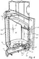
- the stove 1 adapted for indoor use comprises a housing having a bottom wall 10, a top wall 20 and one or more side walls 30a-d defining a combustion chamber 40 adapted to retain a fire.
- the stove 1 also comprises an air supply system 50 for supplying air to the combustion chamber 40.
- the air supply system 50 comprises a primary air conduit 60 for supplying air to the combustion chamber 40 from below through the bottom wall 10 and a secondary air conduit 70 for supplying air to the combustion chamber 40 from above.
- the primary and secondary air conduits 60, 70 are connected to a common inlet 61,
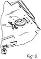
- the size of the common inlet 61 is adjustable. As shown in figures 1 , 2 , 3a and 3b the size of the opening 62 of the common inlet 61 may be manoeuvred to be fully or partly covered, such as with a throttle or valve plate 63.
- the valve plate 63 is manually operable. This is accomplished by a lever 64 which interacts with an arm 63b attached to the plate 63.
- the lever 64 is pivotable about a centre axis 65 such that the arm 63b and the plate 63 is moved to open or close the opening 62 when the lever 64 is manoeuvred by the use of a handle 66 positioned at the, relative to the arm 63b, opposite end of the lever 64.
- the air supply system 50 also comprises a tertiary air conduit 80 for supplying air to an upper portion of the rear wall 30a.
- the tertiary air conduit 80 is connected in parallel with the common inlet 60. Both the tertiary conduit 80 and the common inlet 60 are connected to a common main inlet 90.
- the tertiary air conduit 80 may but is not provided with any throttle or valve. However, when the user manoeuvres the valve plate 63 towards a more closed position a greater amount of air will prefer to enter into the tertiary conduit 80.
- the tertiary air conduit 80 ends at the upper portion of the rear wall 30a with a plurality of small nozzles 81.
- the tertiary air conduit 80 has an entrance opening with a cross-sectional area of about 300-400mm 2 .
- the total cross-sectional area of the nozzles 81 is about 50-150mm 2 .
- the opening 62 has a maximum open cross-sectional area of about 2000-3000mm 2 .
- the main inlet 90 has a cross-sectional area of about 3000-4000mm 2
- the air supply system 50 also comprises a valve 51 arranged in the primary air conduit 60 or in a branching between the primary and secondary air conduits 60, 70.
- the common inlet 61 leads into a box shaped volume 67 which extends below the bottom wall 10 along the rear side of the stove 1.
- the valve 51 is arranged in the wall of the box shaped volume 67 facing the volume 11 underneath the bottom wall 10.
- the secondary conduit 70 connects to the box shaped volume by large openings in the rearward facing walls of the box shaped volume 67.
- the valve 51 is controlled by a bimetal body or blade 52 which is affected by prevailing temperature in the stove 10.
- the bimetal 52 controls the valve 51 such that the valve 51 is in a maximum open position when the prevailing temperature is below a first predetermined temperature (T1) of about 40°C during start-up of a fire. When the bimetal reaches about 40°C it will start to close the valve 51.
- T1 first predetermined temperature
- T2 second predetermined temperature
- the valve 51 may be a so-called pinwheel air damper.
- a valve 51 has typically a first hole pattern in a first part 53 and a second, typically similar, hole pattern in a second part 54.
- the hole patterns are typically shaped as elongate openings extending radially about a central axis about which one of the two parts is rotatable relative to the other.
- the bimetal 52 is at one end 52a fixed relative to one of the parts 53 and interacts at its other end 52b with the rotatable plate 54, such as via a pin 54b attached to the plate 54.
- the valve 51 is shown in figure 5 in its open position.
- the plate 54 is urged in a counter clock wise rotation by a tension spring 55.
- the plate 54 has a protrusion 54a interacting with a pin 53a providing a stop against the force from the tension spring 55.
- the pinwheel air damper 51 is designed such that adjacent holes in the hole pattern are separated by at least 45°, preferably at least 75°. Thereby it is possible to allow the bimetal to deform substantially at still preventing that the pinwheel air damper starts to open again due to excessive movement of the plate 54 such that a hole starts to overlap with the next hole of the hole pattern of the fixed part 53. This way of preventing the pinwheel air damper 51 from reopening when the temperature increases is desirable since there is in such a case no need for any stop-pin or disconnection between the plate 54 and the bimetal 52. However, such designs are of course also conceivable. In the shown embodiment the valve 51 is completely closed in its maximum closed position.
- the bottom wall 10 comprises a grate assembly 100 comprising a first grate part 110 and a second grate part 120.
- the first grate part 110 is movable in a direction M of movement relative to the second grate part 120 by being rotatable about a centre axis A extending along a normal N of a portion of the bottom wall 10 formed by the first and second grate parts 110, 120.
- first grate part 110 and the second grate part 120 both extend in an essentially horizontal direction with the second part 120 underlying the first part 110 in a vertical direction V of the stove 1.
- the second grate part 120 comprises a downwardly extending groove 121 extending along the direction M of movement and being intermittently interrupted along the direction M of movement by through-going openings 122.
- the groove 121 extends along an arc around the centre axis A.
- the first grate part 110 comprises a plurality of through-going openings 112, each through-going opening 112 partly overlying the groove 121 and thereby providing a plurality of channels 123 for a flow 61b of primary air from below via the through-going openings 122 of the second grate part 120 and obliquely along the groove 121 of the second grate part 120 and via the through-going openings 112 of the first grate part 110 up to the combustion chamber 10.
- the first grate part 110 further comprises an ash scraper 113 extending into the groove 121 of the second grate part 120. Movement of the first grate part 110 along the movement direction M will cause the ash scraper 113 to move along the groove 121 and scrape any ash in the groove 121 out of the groove 121 and into the through-going openings 122 interrupting the groove 121.
- the through-going openings 112 of the first part 110 are provided with sidewalls 114a-d extending downwardly to an upper surface of the second grate part 120 thereby forming a top open compartment with a bottom formed by the upper surface of the second grate part 120.
- one of the sidewalls 114d of the through-going openings of the first part 112 extend into the groove 121 thereby forming the ash scraper 113 and an opposing one of the sidewalls 114c of the through-going openings 112 of the first part 110 extending above the groove 121 thereby forming an opening 123 for the obliquely oriented flow 61b along the groove 121.
- the primary air conduit 61 connects to the combustion chamber 40 via a plurality of openings 123 in the bottom wall 10, wherein the openings 123 have a total area of between 1,1 and 5 times, preferably between 1,3 and 3 times an open area of the valve 51 in its maximum open position.
- the total area of the openings 123 is about 700-1100mm 2 , preferably about 900mm 2 .
- the first grate part 110 is manually operated to be moved relative to the second grate part 120 using a handle 115 and lever assembly 116.
- the handle 115 and lever 116 is shown in figure 1 .
- the top part of the lever 116 is shown in figure 5 .
- the handle 115 when the handle 115 is drawn outwardly it will pivot about attachment point 116a and will thereby draw the lever 116 along the long hole 116b.
- the part of the lever 116 shown in figure 5 interacting with the first grate part 110 will thereby cause the first grate part 110 to rotate about 10-15° about the centre axis A in the counter clockwise direction such that the ash scrapers 113 scrape ash from the groove 121.
- the stove 1 comprises a valve 130 for additional supply of air from below.
- the valve 130 is operably connected to the operation of the first grate part 110 for opening and closing of the valve 130.
- figure 5 it is shown how a wire 121 is connected to the lever arm 116.
- the lever 116 is moved, in the figure towards the handle 115. Thereby will the lever 116 tug the wire 131 and will thereby open the latch 130 forming the valve.
- the latch 130 is springloaded by springs 132 towards the closed position.
- the stove is provided with the bimetal controlled valve but is not provided with the grate assembly.
- the stove is provided with the bimetal controlled valve and with the grate assembly.
- the stove is provided with the bimetal controlled valve, the grate assembly and the valve operably connected to the operation of the first grate part.
Landscapes
- Engineering & Computer Science (AREA)
- Chemical & Material Sciences (AREA)
- Combustion & Propulsion (AREA)
- Mechanical Engineering (AREA)
- General Engineering & Computer Science (AREA)
- Physics & Mathematics (AREA)
- Thermal Sciences (AREA)
- Solid-Fuel Combustion (AREA)
Priority Applications (4)
| Application Number | Priority Date | Filing Date | Title |
|---|---|---|---|
| EP16174688.8A EP3258174B1 (en) | 2016-06-16 | 2016-06-16 | Stove |
| DK16174688.8T DK3258174T3 (da) | 2016-06-16 | 2016-06-16 | Ovn |
| CA2970863A CA2970863C (en) | 2016-06-16 | 2017-06-15 | Stove with bimetal air supply control valve |
| US15/623,616 US10677495B2 (en) | 2016-06-16 | 2017-06-15 | Stove |
Applications Claiming Priority (1)
| Application Number | Priority Date | Filing Date | Title |
|---|---|---|---|
| EP16174688.8A EP3258174B1 (en) | 2016-06-16 | 2016-06-16 | Stove |
Publications (2)
| Publication Number | Publication Date |
|---|---|
| EP3258174A1 EP3258174A1 (en) | 2017-12-20 |
| EP3258174B1 true EP3258174B1 (en) | 2020-09-02 |
Family
ID=56137151
Family Applications (1)
| Application Number | Title | Priority Date | Filing Date |
|---|---|---|---|
| EP16174688.8A Active EP3258174B1 (en) | 2016-06-16 | 2016-06-16 | Stove |
Country Status (4)
| Country | Link |
|---|---|
| US (1) | US10677495B2 (da) |
| EP (1) | EP3258174B1 (da) |
| CA (1) | CA2970863C (da) |
| DK (1) | DK3258174T3 (da) |
Families Citing this family (14)
| Publication number | Priority date | Publication date | Assignee | Title |
|---|---|---|---|---|
| WO2020139760A1 (en) | 2018-12-26 | 2020-07-02 | Frontline Advance Llc | Fire pit system |
| US11199324B2 (en) | 2019-03-27 | 2021-12-14 | Solo Dtc Brands, Llc | Combustible fuel burning stove with fire grate |
| US11457771B2 (en) | 2020-03-11 | 2022-10-04 | Solo Brands, Llc | Packable modular combustion grill |
| US11879641B2 (en) | 2021-02-05 | 2024-01-23 | Solo Brands, Llc | Combustible fuel burning fire pit with removable fire grate and ash pan |
| BE1030034B9 (fr) | 2022-05-19 | 2023-07-26 | Jide | Mécanisme manuel d'admission d'air dans la chambre de combustion d'un brûleur pour combustible solide |
| USD1043934S1 (en) | 2022-08-11 | 2024-09-24 | Solo Brands, Llc | Fire pit and stand |
| US12359817B2 (en) | 2022-08-11 | 2025-07-15 | Solo Brands, Llc | Portable stove with folding stand |
| USD1018812S1 (en) | 2022-08-11 | 2024-03-19 | Solo Brands, Llc | Fire pit stand |
| USD1086435S1 (en) | 2022-08-31 | 2025-07-29 | Solo Brands, Llc | Device for fire pit |
| US11774089B1 (en) | 2022-08-31 | 2023-10-03 | Solo Brands, Llc | Combustible fuel burning stove with pellet adapter |
| USD1085403S1 (en) | 2022-08-31 | 2025-07-22 | Solo Brands, Llc | Device for fire pit |
| FI20237134A1 (fi) * | 2023-07-16 | 2025-01-17 | Warma Uunit Oy | Kiinteän polttoaineen tulisija ja menetelmä kiinteän polttoaineen tulisijassa |
| USD1089589S1 (en) | 2024-06-28 | 2025-08-19 | Solo Brands, Llc | Fire pit barrier |
| US12385643B1 (en) | 2024-06-28 | 2025-08-12 | Solo Brands, Llc | Fire pit barrier |
Family Cites Families (12)
| Publication number | Priority date | Publication date | Assignee | Title |
|---|---|---|---|---|
| US3624742A (en) * | 1970-06-15 | 1971-11-30 | Gen Electric | Self-cleaning gas oven with heat exchanger |
| US4169457A (en) * | 1975-09-22 | 1979-10-02 | Shenandoah Manufacturing Co., Inc. | Thermostatically regulated space heaters for burning wood, coal and the like |
| FR2390677A1 (fr) * | 1977-05-09 | 1978-12-08 | Gravier Denis | Dispositif de decendrage pour cheminee a feu ouvert |
| US4265213A (en) | 1978-08-15 | 1981-05-05 | Gorsuch Garald W | Free standing stove |
| WO1983001673A1 (en) * | 1981-10-28 | 1983-05-11 | Barnett, Stockton, G. | Catalytic stove |
| US4624239A (en) * | 1985-12-04 | 1986-11-25 | Bernard Yellin | Barbecue grill damper-ash rake |
| US6216684B1 (en) * | 1999-03-23 | 2001-04-17 | Mark Champion | Wood heater |
| DE10012485B4 (de) | 2000-03-15 | 2004-09-02 | Heybey, Heiko | Einrichtung zur Steuerung der Zufuhr von Verbrennungsluft zum Brennraum einer Einzelfeuerstätte beispielsweise eines Ofens, Kaminofens, Herdes oder dergleichen |
| US7036800B2 (en) * | 2002-04-08 | 2006-05-02 | Ellis Earle R | Automatically controlling the interaction of a medium with an external environment |
| CA2666354A1 (en) | 2006-10-19 | 2008-04-24 | Aduro A/S | A method and device for controlling the supply of combustion air to a combustion chamber |
| DE202007003345U1 (de) | 2007-03-05 | 2008-07-10 | "Skantherm" Wagner Gmbh & Co. Kommanditgesellschaft | Kaminofen |
| DE202015101389U1 (de) | 2015-03-18 | 2015-03-26 | Denis Thum | Kaminkassette mit verbesserter Luftführung |
-
2016
- 2016-06-16 DK DK16174688.8T patent/DK3258174T3/da active
- 2016-06-16 EP EP16174688.8A patent/EP3258174B1/en active Active
-
2017
- 2017-06-15 CA CA2970863A patent/CA2970863C/en active Active
- 2017-06-15 US US15/623,616 patent/US10677495B2/en active Active
Non-Patent Citations (1)
| Title |
|---|
| None * |
Also Published As
| Publication number | Publication date |
|---|---|
| CA2970863A1 (en) | 2017-12-16 |
| CA2970863C (en) | 2026-04-07 |
| US20170363325A1 (en) | 2017-12-21 |
| DK3258174T3 (da) | 2020-11-30 |
| EP3258174A1 (en) | 2017-12-20 |
| US10677495B2 (en) | 2020-06-09 |
Similar Documents
| Publication | Publication Date | Title |
|---|---|---|
| EP3258174B1 (en) | Stove | |
| US5503550A (en) | Gas log fireplace system | |
| US4362146A (en) | Solid fuel stove | |
| US9441839B2 (en) | Heating apparatus with fan | |
| US3096754A (en) | Furnace fireplace | |
| US9115900B2 (en) | Systems and methods for heating water using biofuel | |
| US4582045A (en) | Heating apparatus | |
| CA2944929C (en) | Furnace | |
| EP3765792B1 (en) | Solid fuel heater with three-zone combustion air supply | |
| DK2221534T3 (da) | Brændeovn med en regulering af lufttilførslen | |
| US6488024B2 (en) | Wood heater | |
| US5413088A (en) | Wood burning heating unit | |
| US6216684B1 (en) | Wood heater | |
| US4207860A (en) | Wood-coal heating unit | |
| EP1384031A1 (en) | Burner for pellets | |
| DK166637B1 (da) | Braendeovn | |
| EP1890092B1 (de) | Wohnraumofen für feste Brennstoffe zur Heizung eines Wohnraums und davon entfernten Räumen sowie zur Heizung von sanitärem Warmwasser | |
| KR20180001236A (ko) | 외부 공기조절이 용이한 난로 | |
| KR102011676B1 (ko) | 벽난로 | |
| US7735482B2 (en) | Combustion control system | |
| CA3097261A1 (en) | Solid fuel burning appliance and method to control same | |
| KR102591827B1 (ko) | 열효율을 향상시켜 온실가스 배출을 최소화한 쿡스토브 | |
| US20250031903A1 (en) | Gravity fed smoker | |
| GB2481026A (en) | Space heater with selective flow to divided cavity | |
| EP3527891A1 (de) | Vorwärmsystem für rauchgasleitungen |
Legal Events
| Date | Code | Title | Description |
|---|---|---|---|
| PUAI | Public reference made under article 153(3) epc to a published international application that has entered the european phase |
Free format text: ORIGINAL CODE: 0009012 |
|
| STAA | Information on the status of an ep patent application or granted ep patent |
Free format text: STATUS: THE APPLICATION HAS BEEN PUBLISHED |
|
| AK | Designated contracting states |
Kind code of ref document: A1 Designated state(s): AL AT BE BG CH CY CZ DE DK EE ES FI FR GB GR HR HU IE IS IT LI LT LU LV MC MK MT NL NO PL PT RO RS SE SI SK SM TR |
|
| AX | Request for extension of the european patent |
Extension state: BA ME |
|
| STAA | Information on the status of an ep patent application or granted ep patent |
Free format text: STATUS: REQUEST FOR EXAMINATION WAS MADE |
|
| 17P | Request for examination filed |
Effective date: 20180614 |
|
| RBV | Designated contracting states (corrected) |
Designated state(s): AL AT BE BG CH CY CZ DE DK EE ES FI FR GB GR HR HU IE IS IT LI LT LU LV MC MK MT NL NO PL PT RO RS SE SI SK SM TR |
|
| REG | Reference to a national code |
Ref country code: DE Ref legal event code: R079 Ref document number: 602016043056 Country of ref document: DE Free format text: PREVIOUS MAIN CLASS: F24B0001020000 Ipc: F24H0003000000 |
|
| GRAP | Despatch of communication of intention to grant a patent |
Free format text: ORIGINAL CODE: EPIDOSNIGR1 |
|
| STAA | Information on the status of an ep patent application or granted ep patent |
Free format text: STATUS: GRANT OF PATENT IS INTENDED |
|
| RIC1 | Information provided on ipc code assigned before grant |
Ipc: F24B 5/02 20060101ALI20200324BHEP Ipc: F24H 3/00 20060101AFI20200324BHEP Ipc: F24B 1/02 20060101ALI20200324BHEP Ipc: F24B 1/19 20060101ALI20200324BHEP Ipc: F23H 11/24 20060101ALI20200324BHEP Ipc: F23N 3/04 20060101ALI20200324BHEP Ipc: F24B 1/187 20060101ALI20200324BHEP Ipc: F24B 1/193 20060101ALI20200324BHEP Ipc: F24H 9/20 20060101ALI20200324BHEP |
|
| INTG | Intention to grant announced |
Effective date: 20200408 |
|
| GRAS | Grant fee paid |
Free format text: ORIGINAL CODE: EPIDOSNIGR3 |
|
| GRAA | (expected) grant |
Free format text: ORIGINAL CODE: 0009210 |
|
| STAA | Information on the status of an ep patent application or granted ep patent |
Free format text: STATUS: THE PATENT HAS BEEN GRANTED |
|
| AK | Designated contracting states |
Kind code of ref document: B1 Designated state(s): AL AT BE BG CH CY CZ DE DK EE ES FI FR GB GR HR HU IE IS IT LI LT LU LV MC MK MT NL NO PL PT RO RS SE SI SK SM TR |
|
| REG | Reference to a national code |
Ref country code: GB Ref legal event code: FG4D |
|
| REG | Reference to a national code |
Ref country code: AT Ref legal event code: REF Ref document number: 1309293 Country of ref document: AT Kind code of ref document: T Effective date: 20200915 Ref country code: CH Ref legal event code: EP |
|
| REG | Reference to a national code |
Ref country code: DE Ref legal event code: R096 Ref document number: 602016043056 Country of ref document: DE |
|
| REG | Reference to a national code |
Ref country code: IE Ref legal event code: FG4D |
|
| REG | Reference to a national code |
Ref country code: NO Ref legal event code: T2 Effective date: 20200902 Ref country code: DK Ref legal event code: T3 Effective date: 20201123 |
|
| REG | Reference to a national code |
Ref country code: SE Ref legal event code: TRGR |
|
| REG | Reference to a national code |
Ref country code: LT Ref legal event code: MG4D |
|
| PG25 | Lapsed in a contracting state [announced via postgrant information from national office to epo] |
Ref country code: LT Free format text: LAPSE BECAUSE OF FAILURE TO SUBMIT A TRANSLATION OF THE DESCRIPTION OR TO PAY THE FEE WITHIN THE PRESCRIBED TIME-LIMIT Effective date: 20200902 Ref country code: HR Free format text: LAPSE BECAUSE OF FAILURE TO SUBMIT A TRANSLATION OF THE DESCRIPTION OR TO PAY THE FEE WITHIN THE PRESCRIBED TIME-LIMIT Effective date: 20200902 Ref country code: FI Free format text: LAPSE BECAUSE OF FAILURE TO SUBMIT A TRANSLATION OF THE DESCRIPTION OR TO PAY THE FEE WITHIN THE PRESCRIBED TIME-LIMIT Effective date: 20200902 Ref country code: BG Free format text: LAPSE BECAUSE OF FAILURE TO SUBMIT A TRANSLATION OF THE DESCRIPTION OR TO PAY THE FEE WITHIN THE PRESCRIBED TIME-LIMIT Effective date: 20201202 Ref country code: GR Free format text: LAPSE BECAUSE OF FAILURE TO SUBMIT A TRANSLATION OF THE DESCRIPTION OR TO PAY THE FEE WITHIN THE PRESCRIBED TIME-LIMIT Effective date: 20201203 |
|
| REG | Reference to a national code |
Ref country code: NL Ref legal event code: MP Effective date: 20200902 |
|
| REG | Reference to a national code |
Ref country code: AT Ref legal event code: MK05 Ref document number: 1309293 Country of ref document: AT Kind code of ref document: T Effective date: 20200902 |
|
| PG25 | Lapsed in a contracting state [announced via postgrant information from national office to epo] |
Ref country code: RS Free format text: LAPSE BECAUSE OF FAILURE TO SUBMIT A TRANSLATION OF THE DESCRIPTION OR TO PAY THE FEE WITHIN THE PRESCRIBED TIME-LIMIT Effective date: 20200902 Ref country code: PL Free format text: LAPSE BECAUSE OF FAILURE TO SUBMIT A TRANSLATION OF THE DESCRIPTION OR TO PAY THE FEE WITHIN THE PRESCRIBED TIME-LIMIT Effective date: 20200902 Ref country code: LV Free format text: LAPSE BECAUSE OF FAILURE TO SUBMIT A TRANSLATION OF THE DESCRIPTION OR TO PAY THE FEE WITHIN THE PRESCRIBED TIME-LIMIT Effective date: 20200902 |
|
| PG25 | Lapsed in a contracting state [announced via postgrant information from national office to epo] |
Ref country code: EE Free format text: LAPSE BECAUSE OF FAILURE TO SUBMIT A TRANSLATION OF THE DESCRIPTION OR TO PAY THE FEE WITHIN THE PRESCRIBED TIME-LIMIT Effective date: 20200902 Ref country code: CZ Free format text: LAPSE BECAUSE OF FAILURE TO SUBMIT A TRANSLATION OF THE DESCRIPTION OR TO PAY THE FEE WITHIN THE PRESCRIBED TIME-LIMIT Effective date: 20200902 Ref country code: SM Free format text: LAPSE BECAUSE OF FAILURE TO SUBMIT A TRANSLATION OF THE DESCRIPTION OR TO PAY THE FEE WITHIN THE PRESCRIBED TIME-LIMIT Effective date: 20200902 Ref country code: RO Free format text: LAPSE BECAUSE OF FAILURE TO SUBMIT A TRANSLATION OF THE DESCRIPTION OR TO PAY THE FEE WITHIN THE PRESCRIBED TIME-LIMIT Effective date: 20200902 Ref country code: PT Free format text: LAPSE BECAUSE OF FAILURE TO SUBMIT A TRANSLATION OF THE DESCRIPTION OR TO PAY THE FEE WITHIN THE PRESCRIBED TIME-LIMIT Effective date: 20210104 |
|
| PG25 | Lapsed in a contracting state [announced via postgrant information from national office to epo] |
Ref country code: AL Free format text: LAPSE BECAUSE OF FAILURE TO SUBMIT A TRANSLATION OF THE DESCRIPTION OR TO PAY THE FEE WITHIN THE PRESCRIBED TIME-LIMIT Effective date: 20200902 Ref country code: AT Free format text: LAPSE BECAUSE OF FAILURE TO SUBMIT A TRANSLATION OF THE DESCRIPTION OR TO PAY THE FEE WITHIN THE PRESCRIBED TIME-LIMIT Effective date: 20200902 Ref country code: ES Free format text: LAPSE BECAUSE OF FAILURE TO SUBMIT A TRANSLATION OF THE DESCRIPTION OR TO PAY THE FEE WITHIN THE PRESCRIBED TIME-LIMIT Effective date: 20200902 Ref country code: IS Free format text: LAPSE BECAUSE OF FAILURE TO SUBMIT A TRANSLATION OF THE DESCRIPTION OR TO PAY THE FEE WITHIN THE PRESCRIBED TIME-LIMIT Effective date: 20210102 |
|
| REG | Reference to a national code |
Ref country code: DE Ref legal event code: R097 Ref document number: 602016043056 Country of ref document: DE |
|
| PG25 | Lapsed in a contracting state [announced via postgrant information from national office to epo] |
Ref country code: SK Free format text: LAPSE BECAUSE OF FAILURE TO SUBMIT A TRANSLATION OF THE DESCRIPTION OR TO PAY THE FEE WITHIN THE PRESCRIBED TIME-LIMIT Effective date: 20200902 |
|
| PLBE | No opposition filed within time limit |
Free format text: ORIGINAL CODE: 0009261 |
|
| STAA | Information on the status of an ep patent application or granted ep patent |
Free format text: STATUS: NO OPPOSITION FILED WITHIN TIME LIMIT |
|
| 26N | No opposition filed |
Effective date: 20210603 |
|
| PG25 | Lapsed in a contracting state [announced via postgrant information from national office to epo] |
Ref country code: SI Free format text: LAPSE BECAUSE OF FAILURE TO SUBMIT A TRANSLATION OF THE DESCRIPTION OR TO PAY THE FEE WITHIN THE PRESCRIBED TIME-LIMIT Effective date: 20200902 |
|
| PG25 | Lapsed in a contracting state [announced via postgrant information from national office to epo] |
Ref country code: IT Free format text: LAPSE BECAUSE OF FAILURE TO SUBMIT A TRANSLATION OF THE DESCRIPTION OR TO PAY THE FEE WITHIN THE PRESCRIBED TIME-LIMIT Effective date: 20200902 |
|
| PG25 | Lapsed in a contracting state [announced via postgrant information from national office to epo] |
Ref country code: MC Free format text: LAPSE BECAUSE OF FAILURE TO SUBMIT A TRANSLATION OF THE DESCRIPTION OR TO PAY THE FEE WITHIN THE PRESCRIBED TIME-LIMIT Effective date: 20200902 |
|
| REG | Reference to a national code |
Ref country code: CH Ref legal event code: PL |
|
| REG | Reference to a national code |
Ref country code: BE Ref legal event code: MM Effective date: 20210630 |
|
| PG25 | Lapsed in a contracting state [announced via postgrant information from national office to epo] |
Ref country code: LU Free format text: LAPSE BECAUSE OF NON-PAYMENT OF DUE FEES Effective date: 20210616 |
|
| PG25 | Lapsed in a contracting state [announced via postgrant information from national office to epo] |
Ref country code: LI Free format text: LAPSE BECAUSE OF NON-PAYMENT OF DUE FEES Effective date: 20210630 Ref country code: IE Free format text: LAPSE BECAUSE OF NON-PAYMENT OF DUE FEES Effective date: 20210616 Ref country code: CH Free format text: LAPSE BECAUSE OF NON-PAYMENT OF DUE FEES Effective date: 20210630 |
|
| PG25 | Lapsed in a contracting state [announced via postgrant information from national office to epo] |
Ref country code: BE Free format text: LAPSE BECAUSE OF NON-PAYMENT OF DUE FEES Effective date: 20210630 |
|
| PG25 | Lapsed in a contracting state [announced via postgrant information from national office to epo] |
Ref country code: HU Free format text: LAPSE BECAUSE OF FAILURE TO SUBMIT A TRANSLATION OF THE DESCRIPTION OR TO PAY THE FEE WITHIN THE PRESCRIBED TIME-LIMIT; INVALID AB INITIO Effective date: 20160616 |
|
| PG25 | Lapsed in a contracting state [announced via postgrant information from national office to epo] |
Ref country code: NL Free format text: LAPSE BECAUSE OF NON-PAYMENT OF DUE FEES Effective date: 20200923 Ref country code: CY Free format text: LAPSE BECAUSE OF FAILURE TO SUBMIT A TRANSLATION OF THE DESCRIPTION OR TO PAY THE FEE WITHIN THE PRESCRIBED TIME-LIMIT Effective date: 20200902 |
|
| PG25 | Lapsed in a contracting state [announced via postgrant information from national office to epo] |
Ref country code: MK Free format text: LAPSE BECAUSE OF FAILURE TO SUBMIT A TRANSLATION OF THE DESCRIPTION OR TO PAY THE FEE WITHIN THE PRESCRIBED TIME-LIMIT Effective date: 20200902 |
|
| PG25 | Lapsed in a contracting state [announced via postgrant information from national office to epo] |
Ref country code: MT Free format text: LAPSE BECAUSE OF FAILURE TO SUBMIT A TRANSLATION OF THE DESCRIPTION OR TO PAY THE FEE WITHIN THE PRESCRIBED TIME-LIMIT Effective date: 20200902 |
|
| REG | Reference to a national code |
Ref country code: GB Ref legal event code: 732E Free format text: REGISTERED BETWEEN 20250109 AND 20250115 |
|
| REG | Reference to a national code |
Ref country code: DE Ref legal event code: R081 Ref document number: 602016043056 Country of ref document: DE Owner name: CONTURA AB, SE Free format text: FORMER OWNER: NIBE AB, MARKARYD, SE |
|
| PGFP | Annual fee paid to national office [announced via postgrant information from national office to epo] |
Ref country code: DE Payment date: 20250516 Year of fee payment: 10 |
|
| PGFP | Annual fee paid to national office [announced via postgrant information from national office to epo] |
Ref country code: GB Payment date: 20250515 Year of fee payment: 10 Ref country code: DK Payment date: 20250515 Year of fee payment: 10 |
|
| PGFP | Annual fee paid to national office [announced via postgrant information from national office to epo] |
Ref country code: NO Payment date: 20250516 Year of fee payment: 10 |
|
| PGFP | Annual fee paid to national office [announced via postgrant information from national office to epo] |
Ref country code: FR Payment date: 20250515 Year of fee payment: 10 |
|
| PGFP | Annual fee paid to national office [announced via postgrant information from national office to epo] |
Ref country code: SE Payment date: 20250515 Year of fee payment: 10 |
|
| PG25 | Lapsed in a contracting state [announced via postgrant information from national office to epo] |
Ref country code: TR Free format text: LAPSE BECAUSE OF FAILURE TO SUBMIT A TRANSLATION OF THE DESCRIPTION OR TO PAY THE FEE WITHIN THE PRESCRIBED TIME-LIMIT Effective date: 20200902 |