EP3257806A1 - Verfahren zum betrieb einer hydraulischen dämpfungsvorrichtung für einen hubmast eines flurförderzeugs - Google Patents
Verfahren zum betrieb einer hydraulischen dämpfungsvorrichtung für einen hubmast eines flurförderzeugs Download PDFInfo
- Publication number
- EP3257806A1 EP3257806A1 EP17176397.2A EP17176397A EP3257806A1 EP 3257806 A1 EP3257806 A1 EP 3257806A1 EP 17176397 A EP17176397 A EP 17176397A EP 3257806 A1 EP3257806 A1 EP 3257806A1
- Authority
- EP
- European Patent Office
- Prior art keywords
- mast
- electric motor
- control device
- operating parameters
- operating
- Prior art date
- Legal status (The legal status is an assumption and is not a legal conclusion. Google has not performed a legal analysis and makes no representation as to the accuracy of the status listed.)
- Granted
Links
Images
Classifications
-
- B—PERFORMING OPERATIONS; TRANSPORTING
- B66—HOISTING; LIFTING; HAULING
- B66F—HOISTING, LIFTING, HAULING OR PUSHING, NOT OTHERWISE PROVIDED FOR, e.g. DEVICES WHICH APPLY A LIFTING OR PUSHING FORCE DIRECTLY TO THE SURFACE OF A LOAD
- B66F17/00—Safety devices, e.g. for limiting or indicating lifting force
- B66F17/003—Safety devices, e.g. for limiting or indicating lifting force for fork-lift trucks
-
- B—PERFORMING OPERATIONS; TRANSPORTING
- B66—HOISTING; LIFTING; HAULING
- B66F—HOISTING, LIFTING, HAULING OR PUSHING, NOT OTHERWISE PROVIDED FOR, e.g. DEVICES WHICH APPLY A LIFTING OR PUSHING FORCE DIRECTLY TO THE SURFACE OF A LOAD
- B66F9/00—Devices for lifting or lowering bulky or heavy goods for loading or unloading purposes
- B66F9/06—Devices for lifting or lowering bulky or heavy goods for loading or unloading purposes movable, with their loads, on wheels or the like, e.g. fork-lift trucks
- B66F9/075—Constructional features or details
- B66F9/20—Means for actuating or controlling masts, platforms, or forks
- B66F9/22—Hydraulic devices or systems
-
- B—PERFORMING OPERATIONS; TRANSPORTING
- B66—HOISTING; LIFTING; HAULING
- B66F—HOISTING, LIFTING, HAULING OR PUSHING, NOT OTHERWISE PROVIDED FOR, e.g. DEVICES WHICH APPLY A LIFTING OR PUSHING FORCE DIRECTLY TO THE SURFACE OF A LOAD
- B66F9/00—Devices for lifting or lowering bulky or heavy goods for loading or unloading purposes
- B66F9/06—Devices for lifting or lowering bulky or heavy goods for loading or unloading purposes movable, with their loads, on wheels or the like, e.g. fork-lift trucks
- B66F9/075—Constructional features or details
- B66F9/20—Means for actuating or controlling masts, platforms, or forks
- B66F9/24—Electrical devices or systems
Definitions
- the invention relates to a method for operating a hydraulic damping device for a lift mast of a truck according to claim 1 and to a hydraulic drive for a damping device for a lift mast of a high-lift truck according to claim 6.
- the mast of a high-lift truck is subject to more or less strong deflections depending on the extension height and load. These deflections are not only static, but may also be subject to vibration. They naturally affect the operation of the truck, especially when loading and unloading in high shelves.
- Means are known to measure the deflection of a mast and provide appropriate compensation or damping measures.
- the static deflection can be compensated by appropriate means.
- a swing of the mast can only be muted and rarely made to zero.
- a reach truck with a control device is known, is controlled by the actuation of an operating element, the course of the movement speed of the actuator such that a swinging of the mast is largely avoided.
- the vibration behavior of the mast is characterized in the control device for a plurality of operating parameters.
- the invention relates to the operation of a damping device, in particular one which is hydraulically operated.
- a damping device in particular one which is hydraulically operated.
- at least one hydraulic cylinder is provided, which is articulated on the one hand on the mast holder and on the other hand articulated to the mast.
- Such a hydraulic cylinder may be designed as a mast tilt cylinder.
- the operation of the damping device can also rely on a hydraulic cylinder acting between a displaceable mast holder and a vehicle frame as a mast push cylinder.
- By actuating the hydraulic cylinder designed, for example, as a mast tilt or mast thrust cylinder, which operates counter to the vibration behavior of the mast it is possible to dampen the oscillation of the mast.
- the invention is therefore based on the object to provide a method for operating a hydraulic damping device for a lift mast of a truck or a hydraulic drive for such a damping device.
- the deflection of the lifting mast is measured and the measured values are given to a control device for the damping device.
- the control device determines, in accordance with the measured values, an actuating signal for an electric motor of the damping device driving a hydraulic pump.
- one or more operating parameters are input, from which a timely or imminent deflection of the mast is derivable.
- the Control device generates an advance signal in accordance with the operating parameter (s), and this advance signal results in the generation of a control signal for the electric motor such that the electric motor is operated at a minimum rotational speed. Due to the minimum speed, a time delay for the damping operation is avoided by specifying a minimum speed.
- a speed for a hydraulic cylinder is set by an operator input, for example by means of pedals, joysticks, levers, etc. This should be moved with a speed proportional to the deflection of the operating element.
- This specification is converted in a control device (electronic control) with knowledge of the piston or annular surface of the cylinder in a corresponding volume flow.
- the amount of hydraulic fluid delivered by a pump is set via the specification of a speed for a driving electric motor.
- a valve controlled by the control device determines, via the position of a spool, when the hydraulic cylinder is pressurized and how large the volumetric flow flowing into the hydraulic cylinder is to dampen displacements of the lifting mast.
- the operating parameter or parameters from which imminent or imminent deflections of the mast can be derived to affect the operation of the mast.
- the operating parameter can also affect the adjustment, be it a mast tilt or a mast thrust of the mast.
- the operating parameter or parameters may relate to the operation of the traction drive or another drive on the industrial truck. The use of the traction drive allows to recognize when can be induced by the method of the truck vibrations in the mast. Also can be turned off at the or the operating parameters to an operation of a brake or a brake signal generator.
- the brake vibrations are also triggered in the mast, so that the operation of a brake signal generator or the operation of the brake itself is a good indicator of an expected oscillation of the mast. It can also be provided that the operating parameter is adjusted to a measured acceleration or deceleration. This also triggers vibrations in the mast.
- a measured acceleration or deceleration of the truck can also occur independently of a braking operation or the traction drive, for example by the vehicle driving up a ramp or down a ramp.
- the implementation of the speed specification to the self-adjusting speed is naturally delayed in time. responsible for this are the static friction of the system, the computing time and the signal transmission of the electronic control as well as the inertia of the movement elements. This delay, which is also referred to as dead time, leads to a relatively large value, especially in the case of erratic operator inputs from the idle state. Of course, the same applies if the speed default is not generated by controls, but within an electronic control device.
- the motor that drives the hydraulic pump is an electric motor, it is demagnetized at rest and consumes no energy. If the motor is set in motion from rest, it must first be magnetized and static friction forces have to be overcome. Similarly, reversing the speed from a positive to a negative speed or vice versa to a zero crossing of the speed at which the electric motor is demagnetized and stands still for a short time.
- a number of operating parameters of the vehicle can be present or measured, which individually or in combination indicate that a deflection or oscillation of the lifting mast is to be expected.
- the lifting device gets a signal in the mast to raise a load to a certain height. It is obvious that lifting from a ground-level position initially does not lead to a noticeable deflection or oscillation of the mast, but only occurs when the load has reached a certain height.
- the advance signal is generated according to the invention, according to which the electric motor for the drive of the damping device is already set at a minimum speed in motion.
- This premature starting of the electric motor has the great advantage that a faster response to the upcoming damping operation is possible. Due to the premature drive of the electric motor this is already magnetized and it is the static friction forces overcome. Also can be maintained with the help of the advance operation of the electric motor in the hydraulic elements, a pressure that would otherwise have to be established only after the start of the pump at the start of the damping operation. In addition, a caster of the engine is after a procedure of the hydraulic cylinder possible because after an operator input another default is likely.
- the speed of the electric motor in advance operation can be very small, since - as I said - static friction and pressure build-up can be overcome or done even at this speed to keep the reaction time as small as possible.
- the operation of the electric motor with the minimum speed takes place only for a limited period. Either a further operation of the electric motor or the hydraulic drive is not required subsequently or already during the period, the startup of the electric motor at operating speed to the corresponding drive of the pump and the corresponding supply of the hydraulic cylinder for the damping device.
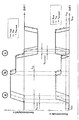
- the first diagram shows the velocity profile of a hydraulic cylinder over time for the course of a target speed, an actual speed and a standby speed.
- the second diagram shows the course of the speed of an electric motor for a target speed, an actual speed and a standby speed.
- the operational system keeps the minimum speed n min , so that the following jump can be implemented faster.
- the hydraulic cylinder is at rest for less time and t tot , reversal is smaller.
- the end of the ready operation is terminated because a defined time has passed after completion of the setpoint specification and an operating situation is reached in which a fast response is not found to be necessary.
Landscapes
- Engineering & Computer Science (AREA)
- Structural Engineering (AREA)
- Transportation (AREA)
- Life Sciences & Earth Sciences (AREA)
- Geology (AREA)
- Mechanical Engineering (AREA)
- Chemical & Material Sciences (AREA)
- Combustion & Propulsion (AREA)
- Civil Engineering (AREA)
- Forklifts And Lifting Vehicles (AREA)
Abstract
Description
- Die Erfindung bezieht sich auf ein Verfahren zum Betrieb einer hydraulischen Dämpfungsvorrichtung für einen Hubmast eines Flurförderzeugs nach Anspruch 1 und auf einen hydraulischen Antrieb für eine Dämpfungsvorrichtung für einen Hubmast eines Hochhubflurförderzeugs nach Anspruch 6.
- Der Hubmast eines Hochhubfahrzeugs ist je nach Ausfahrhöhe und Belastung mehr oder weniger starken Durchbiegungen ausgesetzt. Diese Durchbiegungen sind nicht nur statisch, sondern können auch Schwingungen unterliegen. Sie beeinträchtigen naturgemäß den Betrieb des Flurförderzeugs, insbesondere beim Ein- und Ausstapeln bei Hochregalen.
- Es sind Mittel bekannt, die Auslenkung eines Mastes zu messen und entsprechende Kompensations- oder Dämpfungsmaßnahmen vorzusehen. Die statische Auslenkung kann durch entsprechende Mittel kompensiert werden. Ein Schwingen des Mastes kann nur gedämpft und selten zu Null gemacht werden.
- Aus
DE 10 2007 024 817 A1 ist ein Schubmaststapler mit einer Steuervorrichtung bekannt geworden, mit der nach einer Betätigung eines Bedienelements der Verlauf der Bewegungsgeschwindigkeit des Stellglieds derart gesteuert wird, dass ein Schwingen des Hubgerüsts weitgehend vermieden wird. Zur Vermeidung von Schwingungen ist in der Steuervorrichtung für mehrere Betriebsparameter das Schwingungsverhalten des Hubgerüsts charakterisiert. - Aus
US 2014/0277871 A1 ist ein System bekannt, mit dem eine Hubeinrichtung angesteuert werden kann, um innerhalb vorgegebener Grenzen zu bleiben. Der Steueralgorithmus hierfür analysiert ein vorhergesagtes Verhaltens des Fahrzeugs, um einen Leistungsparameter des Fahrzeugs entsprechend anzusteuern. - Die Erfindung bezieht sich auf den Betrieb einer Dämpfungsvorrichtung, insbesondere einer solchen, die hydraulisch betrieben wird. Zu diesem Zweck ist mindestens ein Hydraulikzylinder vorgesehen, der einerseits am Masthalter angelenkt und andererseits gelenkig mit dem Hubmast verbunden ist. Ein solcher Hydraulikzylinder kann als ein Mastneigezylinder ausgeführt sein. Auch kann der Betrieb der Dämpfungsvorrichtung auf einen zwischen einem verschieblichen Masthalter und einem Fahrzeugrahmen wirkenden Hydraulikzylinder als Mastschubzylinder zurückgreifen. Durch eine Betätigung des beispielsweise als Mastneige- oder Mastschubzylinder ausgebildeten Hydraulikzylinders, der dem Schwingungsverhalten des Mastes entgegengesetzt arbeitet, ist es möglich, die Schwingung des Mastes zu dämpfen.
- Der Erfindung liegt daher die Aufgabe zugrunde, ein Verfahren zum Betrieb einer hydraulischen Dämpfungsvorrichtung für einen Hubmast eines Flurförderzeugs zu schaffen bzw. einen hydraulischen Antrieb für eine derartige Dämpfungseinrichtung.
- Diese Aufgabe wird durch die Merkmale der Ansprüche 1 und 6 gelöst.
- Bei dem erfindungsgemäßen Verfahren wird die Auslenkung des Hubmastes gemessen und die Messwerte werden in eine Steuervorrichtung für die Dämpfungsvorrichtung gegeben. Die Steuervorrichtung ermittelt nach Maßgabe der Messwerte ein Stellsignal für einen eine Hydraulikpumpe antreibenden Elektromotor der Dämpfungsvorrichtung. In die Steuervorrichtung werden auch ein oder mehrerer Betriebsparameter eingegeben, aus welchen eine zeitnah oder unmittelbar bevorstehende Auslenkung des Hubmastes ableitbar ist. Die Steuervorrichtung erzeugt nach Maßgabe des oder der Betriebsparameter ein Voraussignal, und dieses Voraussignal führt zur Erzeugung eines Stellsignals für den Elektromotor derart, dass der Elektromotor mit einer minimalen Drehzahl in Betrieb gesetzt wird. Durch die minimale Drehzahl wird durch Vorgabe einer Minimaldrehzahl eine zeitliche Verzögerung für den Dämpfungsbetrieb vermieden.
- Bei der Erfindung wird von folgenden Überlegungen ausgegangen. Bei der Bedienung eines hydraulischen Antriebs wird durch eine Bedieneingabe, zum Beispiel mittels Pedalen, Steuerknüppeln, Hebeln usw. eine Geschwindigkeit für einen hydraulischen Zylinder vorgegeben. Dieser soll mit einer zur Auslenkung des Bedienelements proportionalen Geschwindigkeit bewegt werden. Diese Vorgabe wird in einer Steuervorrichtung (elektronische Steuerung) mit Kenntnis der Kolben- oder Ringfläche des Zylinders in einen entsprechenden Volumenstrom umgerechnet. Um diesen Volumenstrom zu erreichen, wird die Menge des von einer Pumpe geförderten Hydraulikmediums über die Vorgabe einer Drehzahl für einen antreibenden Elektromotor eingestellt. Ein von der Steuervorrichtung gesteuertes Ventil bestimmt über die Stellung eines Schiebers, wann der Hydraulikzylinder beaufschlagt wird und wie groß der in den Hydraulikzylinder fließende Volumenstrom ist, um Auslenkungen des Hubmastes zu dämpfen.
- In einer bevorzugten Weiterbildung des erfindungsgemäßen Verfahrens ist vorgesehen, dass der oder die Betriebsparameter, aus welchen zeitnah oder unmittelbar bevorstehende Auslenkungen des Mastes ableitbar sind, den Betrieb des Hubmastes betreffen. Bei der Verwendung eines Hubmastes kann der Betriebsparameter auch die Verstellbewegung, sei es eine Mastneigung oder ein Mastschub des Mastes betreffen. Ferner können alternativ oder zusätzlich der oder die Betriebsparameter den Betrieb des Fahrantriebs oder eines anderen Antriebs an dem Flurförderzeug betreffen. Die Verwendung des Fahrantriebs erlaubt es, zu erkennen, wann durch das Verfahren des Flurförderzeugs Schwingungen in dem Hubmast induziert werden können. Ebenfalls kann bei dem oder den Betriebsparametern auf eine Betätigung einer Bremse oder eines Bremssignalgebers abgestellt werden. Durch den Einsatz der Bremse werden ebenfalls Schwingungen in dem Hubgerüst ausgelöst, so dass die Betätigung eines Bremssignalgebers oder die Betätigung der Bremse selbst ein guter Indikator für eine zu erwartende Schwingung des Hubgerüsts ist. Auch kann vorgesehen sein, dass als Betriebsparameter auf eine gemessene Beschleunigung oder Verzögerung abgestellt wird. Diese löst ebenfalls Schwingungen in dem Hubgerüst aus. Eine gemessene Beschleunigung oder Verzögerung des Flurförderzeugs kann auch unabhängig von einem Bremsvorgang oder dem Fahrantrieb auftreten, beispielsweise indem das Fahrzeug eine Rampe hinauf oder eine Rampe hinunter fährt.
- Die Umsetzung der Geschwindigkeitsvorgabe zu der sich einstellenden Geschwindigkeit erfolgt naturgemäß zeitlich verzögert. Verantwortlich hierfür sind die Haftreibung des Systems, die Rechenzeit und die Signalübertragung der elektronischen Steuerung sowie auch die Massenträgheit der Bewegungselemente. Diese Verzögerung, die auch als Totzeit bezeichnet wird, führt insbesondere bei sprunghaften Bedieneingaben aus dem Ruhezustand zu einem relativ großen Wert. Das gleiche gilt natürlich auch, wenn die Geschwindigkeitsvorgabe nicht durch Bedienelemente, sondern innerhalb einer elektronischen Steuervorrichtung erzeugt wird.
- Ist der Motor, der die Hydraulikpumpe antreibt, ein Elektromotor, ist dieser im Ruhezustand entmagnetisiert und verbraucht keine Energie. Wird der Motor aus der Ruhe in Bewegung gesetzt, muss erst eine Magnetisierung erfolgen, und es müssen Haftreibungskräfte überwunden werden. Ebenso kommt es beim Umkehren der Geschwindigkeit von einer positiven zu einer negativen Geschwindigkeit oder umgekehrt zu einem Nulldurchgang der Geschwindigkeit, bei dem der Elektromotor entmagnetisiert wird und für kurze Zeit stillsteht.
- Deshalb ist bei der Erfindung vorgesehen, vor dem Eintreten des Dämpfungsbetriebes den Elektromotor mit einer minimalen Drehzahl zu betreiben, unabhängig von der im Dämpfungsbetrieb vorgegebenen Geschwindigkeit durch die Steuervorrichtung oder einen Bediener.
- Bei der Erfindung wird davon Gebrauch gemacht, dass für den Betrieb eines Hubmastes eines Hochhubfahrzeugs eine Reihe von Betriebsparametern des Fahrzeugs vorliegen bzw. gemessen werden können, die einzeln oder in Kombination andeuten, dass eine Auslenkung bzw. Schwingung des Hubmastes zu erwarten steht. Als Beispiel sei genannt, dass die Hubvorrichtung im Hubmast ein Signal bekommt, eine Last auf eine bestimmte Höhe anzuheben. Es liegt auf der Hand, dass das Anheben aus einer bodennahen Position zunächst noch nicht zu einer merklichen Auslenkung oder Schwingung des Mastes führt, sondern diese erst eintritt, wenn die Last eine bestimmte Höhe erreicht hat. Bei Vorliegen eines derartigen Betriebszustands wird erfindungsgemäß das Voraussignal erzeugt, nach Maßgabe dessen der Elektromotor für den Antrieb der Dämpfungsvorrichtung bereits mit einer minimalen Drehzahl in Gang gesetzt wird. Dieses vorzeitige Ingangsetzen des Elektromotors hat den großen Vorteil, dass eine schnellere Reaktion auf den bevorstehenden Dämpfungsbetrieb ermöglicht ist. Durch den vorzeitigen Antrieb des Elektromotors ist dieser bereits magnetisiert und es sind die Haftreibungskräfte überwunden. Ebenfalls kann mit Hilfe des Vorausbetriebs des Elektromotors in den hydraulischen Elementen ein Druck vorgehalten werden, der sonst erst nach Anlauf der Pumpe beim Start des Dämpfungsbetriebs aufgebaut werden müsste. Außerdem ist auch ein Nachlauf des Motors nach einem Verfahren des Hydraulikzylinders möglich, da nach einer Bedieneingabe eine weitere Vorgabe wahrscheinlich ist.
- Die Drehzahl des Elektromotors im Vorausbetrieb kann sehr klein sein, da - wie gesagt - Haftreibungskräfte und Druckaufbau auch bei dieser Geschwindigkeit überwunden bzw. erfolgen können, um die Reaktionszeit möglichst klein zu halten.
- Der Betrieb des Elektromotors mit der minimalen Drehzahl findet nur über einen begrenzten Zeitraum statt. Entweder wird im Anschluss ein weiterer Betrieb des Elektromotors bzw. des hydraulischen Antriebs nicht gefordert oder aber bereits während des Zeitraums erfolgt das Hochfahren des Elektromotors mit Betriebsdrehzahl zum entsprechenden Antrieb der Pumpe und zur entsprechenden Versorgung des Hydraulikzylinders für die Dämpfungsvorrichtung.
- Die Erfindung wird nachfolgend anhand von zwei Diagrammen näher erläutert.
- Das erste Diagramm zeigt das Geschwindigkeitsprofil eines Hydraulikzylinders über der Zeit für den Verlauf einer Soll-Geschwindigkeit, einer Ist-Geschwindigkeit und einer Bereitschaftsgeschwindigkeit.
- Das zweite Diagramm zeigt den Verlauf der Drehzahl eines Elektromotors für eine Soll-Drehzahl, eine Ist-Drehzahl und eine Bereitschaftsdrehzahl.
- In dem Geschwindigkeitsprofil mit dem zugehörigen Profil für die Motordrehzahl ist das unterschiedliche Verhalten eines Hydrauliksystems mit und ohne einsatzbereitem Betrieb gezeigt. Zum Zeitpunkt Tstart wird ein Betriebszustand erreicht, zu dem der Motor in Bereitschaft versetzt wird und die minimale Drehzahl Nmin vorgegeben wird. In der Situation A steigt die Sollwert-Vorgabe Vsoll der Geschwindigkeit sprunghaft an. Die Geschwindigkeit des betriebsbereiten Systems Vist, bereit folgt diesem Signal schneller als die Geschwindigkeit Vist, da die Totzeit tTot, Ruhe für diesen Fall geringer ist. In Situation b ist das Verhalten beider Systeme gleich, da die Veränderung nur Auswirkungen auf das Verhalten um die Ruhelage hat, wodurch die Totzeit tTot gleich ist. Die Umkehr der Bewegungsrichtung ist in Situation c dargestellt. Trotz Nulldurchgang des Sollwerts hält das betriebsbereite System die Mindestdrehzahl nmin, sodass der folgende Sprung schneller umgesetzt werden kann. Der Hydraulikzylinder befindet sich weniger lange in Ruhe und tTot, Umkehr ist kleiner. Zum Zeitpunkt tEnde wird der einsatzbereite Betrieb beendet, da eine definierte Zeit nach Beendigung der Sollwertvorgabe vergangen ist und eine Betriebssituation erreicht ist, in der ein schnelles Reaktionsverhalten nicht für nötig befunden wird.
- Wie aus dem Drehzahldiagramm hervorgeht, ist nur eine geringe Drehzahl erforderlich, um eine kürzere Reaktionszeit zu erhalten.
Claims (12)
- Verfahren zum Betrieb einer hydraulischen Dämpfungsvorrichtung für einen Hubmast eines Flurförderzeugs, bei dem Auslenkungen des Hubmastes gemessen und die Messwerte in eine Steuervorrichtung für die Dämpfungsvorrichtung gegeben werden und die Steuervorrichtung nach Maßgabe der Messwerte Stellsignale für einen eine Hydraulikpumpe antreibenden Elektromotor erzeugt, bei dem ferner in der Steuervorrichtung ein oder mehrere Betriebsparameter gespeichert werden, aus welchen eine zeitnah oder unmittelbar bevorstehende Auslenkung des Mastes ableitbar ist und die Steuervorrichtung nach Maßgabe der Betriebsparameter ein Voraussignal erzeugt zur Erzeugung eines Stellsignals für den Elektromotor derart, dass der Elektromotor mit einer minimalen Drehzahl in Betrieb gesetzt wird.
- Verfahren nach Anspruch 1, dadurch gekennzeichnet, dass der oder die Betriebsparameter den Betrieb des Mastes betreffen.
- Verfahren nach Anspruch 1 oder 2, dadurch gekennzeichnet, dass der oder die Betriebsparameter den Betrieb des Fahrantriebs oder einen sonstige Antrieb des Flurförderzeugs betreffen.
- Verfahren nach einem der Ansprüche 1 bis 3, dadurch gekennzeichnet, dass der oder die Betriebsparameter eine Betätigung einer Bremse und/oder eines Bremssignalgebers betreffen.
- Verfahren nach einem der Ansprüche 1 bis 4, dadurch gekennzeichnet, dass der oder die Betriebsparameter eine gemessene Beschleunigung oder Verzögerung betreffen.
- Hydraulischer Antrieb für eine Dämpfungseinrichtung für einen Hubmast eines Hochhubflurförderzeugs, wobei der Antrieb einen Elektromotor, eine von dem Elektromotor angetriebene Pumpe und mindestens einen von der Pumpe angetriebenen Hydraulikzylinder und eine Steuervorrichtung aufweist, die den Hydraulikzylinder nach Maßgabe der Auslenkung des Hubmastes gegenüber der Vertikalen zur Dämpfung der Auslenkung aktiviert, dadurch gekennzeichnet, dass die Steuervorrichtung aus einem oder mehreren Betriebsparametern für den Hubmast ableitet, dass eine Auslenkung des Mastes zeitnah oder unmittelbar bevorsteht und ein Voraussignal erzeugt und die Steuervorrichtung nach Maßgabe des Voraus signals ein Stellsignal für den Elektromotor erzeugt, derart, dass dieser mit einer minimalen Drehzahl in Betrieb gesetzt wird und die Pumpe über ein Steuerventil den Hydraulikzylinder mit Hydraulikmedium versorgt.
- Hydraulischer Antrieb nach Anspruch 6, dadurch gekennzeichnet, dass die minimale Drehzahl kleiner ist als eine Drehzahl des Elektromotors in einemDämpfungsbetrieb.
- Vorrichtung nach einem der Ansprüche 1 bis 3, dadurch gekennzeichnet, dass der Betrieb des Elektromotors mit der minimalen Drehzahl nach einem begrenzten Zeitraum beendet wird.
- Vorrichtung nach einem der Ansprüche 6bis 8, dadurch gekennzeichnet, dass der oder die Betriebsparameter den Betrieb des Hubmastes betreffen.
- Vorrichtung nach einem der Ansprüche 6 bis 9, dadurch gekennzeichnet, dass der oder die Betriebsparameter den Betrieb des Fahrantriebes oder einen sonstigen Antrieb betreffen.
- Vorrichtung nach eine der Ansprüche 6 bis 10, dadurch gekennzeichnet, dass der die Betriebsparameter eine Betätigung eines Bremse und/oder eines Bremssignalgebers betreffen.
- Vorrichtung nach einem der Ansprüche 6 bis 11, dadurch gekennzeichnet, dass ein Sensor vorgesehen ist, der eine Beschleunigung oder Verzögerung erfasst und die an die Steuervorrichtung als Betriebsparameter anliegt.
Applications Claiming Priority (1)
| Application Number | Priority Date | Filing Date | Title |
|---|---|---|---|
| DE102016111109.0A DE102016111109A1 (de) | 2016-06-17 | 2016-06-17 | Verfahren zum Betrieb einer hydraulischen Dämpfungsvorrichtung für einen Hubmast eines Flurförderzeugs |
Publications (2)
| Publication Number | Publication Date |
|---|---|
| EP3257806A1 true EP3257806A1 (de) | 2017-12-20 |
| EP3257806B1 EP3257806B1 (de) | 2020-03-04 |
Family
ID=59070545
Family Applications (1)
| Application Number | Title | Priority Date | Filing Date |
|---|---|---|---|
| EP17176397.2A Active EP3257806B1 (de) | 2016-06-17 | 2017-06-16 | Verfahren zum betrieb einer hydraulischen dämpfungsvorrichtung für einen hubmast eines flurförderzeugs und hydraulischer antrieb für eine dämpfungseinrichtung |
Country Status (2)
| Country | Link |
|---|---|
| EP (1) | EP3257806B1 (de) |
| DE (1) | DE102016111109A1 (de) |
Citations (5)
| Publication number | Priority date | Publication date | Assignee | Title |
|---|---|---|---|---|
| JPH01247304A (ja) * | 1988-03-28 | 1989-10-03 | Seibu Electric & Mach Co Ltd | スタッカークレーンのマスト揺れ防止方法 |
| DE10349123A1 (de) * | 2003-10-22 | 2005-05-19 | Still Wagner Gmbh & Co Kg | Hubwerk, insbesondere für einen Hochregalstapler |
| DE102007024817A1 (de) * | 2007-03-30 | 2008-10-09 | Linde Material Handling Gmbh | Flurförderzeug mit einem Hubgerüst und einem Stellglied zur Kompensation von Schwingungen |
| DE102008025631A1 (de) * | 2008-05-26 | 2009-12-03 | Jungheinrich Ag | Verfahren zur Betätigung mindestens einer hydraulischen Vorrichtung an einem Hubgerüst eines Flurförderzeugs |
| US20140277871A1 (en) * | 2013-03-14 | 2014-09-18 | Fernando D. Goncalves | Systems and methods for maintaining an industrial lift truck within defined bounds |
-
2016
- 2016-06-17 DE DE102016111109.0A patent/DE102016111109A1/de not_active Withdrawn
-
2017
- 2017-06-16 EP EP17176397.2A patent/EP3257806B1/de active Active
Patent Citations (5)
| Publication number | Priority date | Publication date | Assignee | Title |
|---|---|---|---|---|
| JPH01247304A (ja) * | 1988-03-28 | 1989-10-03 | Seibu Electric & Mach Co Ltd | スタッカークレーンのマスト揺れ防止方法 |
| DE10349123A1 (de) * | 2003-10-22 | 2005-05-19 | Still Wagner Gmbh & Co Kg | Hubwerk, insbesondere für einen Hochregalstapler |
| DE102007024817A1 (de) * | 2007-03-30 | 2008-10-09 | Linde Material Handling Gmbh | Flurförderzeug mit einem Hubgerüst und einem Stellglied zur Kompensation von Schwingungen |
| DE102008025631A1 (de) * | 2008-05-26 | 2009-12-03 | Jungheinrich Ag | Verfahren zur Betätigung mindestens einer hydraulischen Vorrichtung an einem Hubgerüst eines Flurförderzeugs |
| US20140277871A1 (en) * | 2013-03-14 | 2014-09-18 | Fernando D. Goncalves | Systems and methods for maintaining an industrial lift truck within defined bounds |
Also Published As
| Publication number | Publication date |
|---|---|
| DE102016111109A1 (de) | 2017-12-21 |
| EP3257806B1 (de) | 2020-03-04 |
Similar Documents
| Publication | Publication Date | Title |
|---|---|---|
| EP1067319B2 (de) | Einrichtung zum Steuern einer Stelleinrichtung für ein Getriebe | |
| EP2580095B1 (de) | Verfahren und vorrichtung zur regelung eines elektrohydraulischen bremssystems für kraftfahrzeuge | |
| DE112012000056B4 (de) | Gabelstapler und Kriechgangsteuerverfahren eines Gabelstaplers | |
| EP2050961B1 (de) | Hydraulisches Antriebssystem | |
| DE102016213236B4 (de) | Elektronische ventilbetätigungsteuerung und druckkompensierung | |
| EP2305524B2 (de) | Verfahren zum Betrieb einer Bremseinrichtung für ein hydraulisch gebremstes Zugfahrzeug | |
| DE69706384T2 (de) | Hubsteuereinrichtung und -Verfahren | |
| DE102013006137A1 (de) | Regelung drehzahlvariabler Verstellpumpen mittels modellbasierter Optimierung | |
| WO1998034868A1 (de) | Verfahren sowie vorrichtung zur steuerung eines hydraulischen aufzugs | |
| EP0097275B1 (de) | Verfahren zum Betrieb eines hydrostatischen oder pneumatischen Antriebs sowie Antrieb | |
| EP4281282B1 (de) | Hydraulische umformmaschine zum pressen von werkstücken, insbesondere schmiedehammer, und verfahren zum betreiben einer hydraulischen umformmaschine, insbesondere eines schmiedehammers | |
| DE102007024817B4 (de) | Flurförderzeug mit einem Hubgerüst und einem Stellglied zur Kompensation von Schwingungen | |
| DE60034387T2 (de) | Verfahren zur Bedienung eines Kranes | |
| DE102021201895A1 (de) | Verfahren zum Betreiben einer drehzahlvariablen, elektrohydraulischen Pumpe, Recheneinheit und drehzahlvariable elektro-hydraulische Pumpe | |
| DE69706383T2 (de) | Verfahren und Vorrichtung zum Heben | |
| WO2018210448A2 (de) | Verfahren zum betrieb einer pulverpresse mit lagenregelung und pulverpresse zur ausführung des verfahrens | |
| DE10163066A1 (de) | Verfahren zur aktiven Schwingungsdämpfung für eine mobile Arbeitsmaschine | |
| EP3249241B1 (de) | Verfahren zur feststellung der endlagenposition eines hydraulikzylinders einer arbeitshydraulik einer mobilen arbeitsmaschine, insbesondere eines flurförderzeugs | |
| WO2021259981A1 (de) | Verfahren zum betreiben eines hydraulischen antriebs | |
| DE102021213085B4 (de) | Verfahren zum Dämpfen eines beweglich gelagerten Anbauteils einer Maschine und Maschine | |
| EP4000174B1 (de) | Vorrichtung und verfahren zur steuerung oder regelung einer bewegung eines ziehkissens einer ziehkissenpresse | |
| EP1882102B1 (de) | Fluidisch betätigter antrieb sowie verfahren zur steuerung desselben | |
| DE102022206535A1 (de) | Verfahren zur Regelung von hydraulischen Komponenten | |
| DE102015222672A1 (de) | Verfahren zum Betreiben einer elektro-hydraulischen Achse und elektro-hydraulische Achse | |
| EP3257806B1 (de) | Verfahren zum betrieb einer hydraulischen dämpfungsvorrichtung für einen hubmast eines flurförderzeugs und hydraulischer antrieb für eine dämpfungseinrichtung |
Legal Events
| Date | Code | Title | Description |
|---|---|---|---|
| PUAI | Public reference made under article 153(3) epc to a published international application that has entered the european phase |
Free format text: ORIGINAL CODE: 0009012 |
|
| STAA | Information on the status of an ep patent application or granted ep patent |
Free format text: STATUS: THE APPLICATION HAS BEEN PUBLISHED |
|
| AK | Designated contracting states |
Kind code of ref document: A1 Designated state(s): AL AT BE BG CH CY CZ DE DK EE ES FI FR GB GR HR HU IE IS IT LI LT LU LV MC MK MT NL NO PL PT RO RS SE SI SK SM TR |
|
| AX | Request for extension of the european patent |
Extension state: BA ME |
|
| STAA | Information on the status of an ep patent application or granted ep patent |
Free format text: STATUS: REQUEST FOR EXAMINATION WAS MADE |
|
| 17P | Request for examination filed |
Effective date: 20180611 |
|
| RBV | Designated contracting states (corrected) |
Designated state(s): AL AT BE BG CH CY CZ DE DK EE ES FI FR GB GR HR HU IE IS IT LI LT LU LV MC MK MT NL NO PL PT RO RS SE SI SK SM TR |
|
| STAA | Information on the status of an ep patent application or granted ep patent |
Free format text: STATUS: EXAMINATION IS IN PROGRESS |
|
| 17Q | First examination report despatched |
Effective date: 20190315 |
|
| GRAP | Despatch of communication of intention to grant a patent |
Free format text: ORIGINAL CODE: EPIDOSNIGR1 |
|
| STAA | Information on the status of an ep patent application or granted ep patent |
Free format text: STATUS: GRANT OF PATENT IS INTENDED |
|
| INTG | Intention to grant announced |
Effective date: 20191024 |
|
| GRAS | Grant fee paid |
Free format text: ORIGINAL CODE: EPIDOSNIGR3 |
|
| GRAA | (expected) grant |
Free format text: ORIGINAL CODE: 0009210 |
|
| STAA | Information on the status of an ep patent application or granted ep patent |
Free format text: STATUS: THE PATENT HAS BEEN GRANTED |
|
| AK | Designated contracting states |
Kind code of ref document: B1 Designated state(s): AL AT BE BG CH CY CZ DE DK EE ES FI FR GB GR HR HU IE IS IT LI LT LU LV MC MK MT NL NO PL PT RO RS SE SI SK SM TR |
|
| REG | Reference to a national code |
Ref country code: GB Ref legal event code: FG4D Free format text: NOT ENGLISH |
|
| REG | Reference to a national code |
Ref country code: CH Ref legal event code: EP |
|
| REG | Reference to a national code |
Ref country code: AT Ref legal event code: REF Ref document number: 1240163 Country of ref document: AT Kind code of ref document: T Effective date: 20200315 |
|
| REG | Reference to a national code |
Ref country code: DE Ref legal event code: R096 Ref document number: 502017004052 Country of ref document: DE |
|
| REG | Reference to a national code |
Ref country code: IE Ref legal event code: FG4D Free format text: LANGUAGE OF EP DOCUMENT: GERMAN |
|
| PG25 | Lapsed in a contracting state [announced via postgrant information from national office to epo] |
Ref country code: RS Free format text: LAPSE BECAUSE OF FAILURE TO SUBMIT A TRANSLATION OF THE DESCRIPTION OR TO PAY THE FEE WITHIN THE PRESCRIBED TIME-LIMIT Effective date: 20200304 Ref country code: FI Free format text: LAPSE BECAUSE OF FAILURE TO SUBMIT A TRANSLATION OF THE DESCRIPTION OR TO PAY THE FEE WITHIN THE PRESCRIBED TIME-LIMIT Effective date: 20200304 Ref country code: NO Free format text: LAPSE BECAUSE OF FAILURE TO SUBMIT A TRANSLATION OF THE DESCRIPTION OR TO PAY THE FEE WITHIN THE PRESCRIBED TIME-LIMIT Effective date: 20200604 |
|
| REG | Reference to a national code |
Ref country code: NL Ref legal event code: MP Effective date: 20200304 |
|
| PG25 | Lapsed in a contracting state [announced via postgrant information from national office to epo] |
Ref country code: LV Free format text: LAPSE BECAUSE OF FAILURE TO SUBMIT A TRANSLATION OF THE DESCRIPTION OR TO PAY THE FEE WITHIN THE PRESCRIBED TIME-LIMIT Effective date: 20200304 Ref country code: SE Free format text: LAPSE BECAUSE OF FAILURE TO SUBMIT A TRANSLATION OF THE DESCRIPTION OR TO PAY THE FEE WITHIN THE PRESCRIBED TIME-LIMIT Effective date: 20200304 Ref country code: BG Free format text: LAPSE BECAUSE OF FAILURE TO SUBMIT A TRANSLATION OF THE DESCRIPTION OR TO PAY THE FEE WITHIN THE PRESCRIBED TIME-LIMIT Effective date: 20200604 Ref country code: HR Free format text: LAPSE BECAUSE OF FAILURE TO SUBMIT A TRANSLATION OF THE DESCRIPTION OR TO PAY THE FEE WITHIN THE PRESCRIBED TIME-LIMIT Effective date: 20200304 Ref country code: GR Free format text: LAPSE BECAUSE OF FAILURE TO SUBMIT A TRANSLATION OF THE DESCRIPTION OR TO PAY THE FEE WITHIN THE PRESCRIBED TIME-LIMIT Effective date: 20200605 |
|
| REG | Reference to a national code |
Ref country code: LT Ref legal event code: MG4D |
|
| PG25 | Lapsed in a contracting state [announced via postgrant information from national office to epo] |
Ref country code: NL Free format text: LAPSE BECAUSE OF FAILURE TO SUBMIT A TRANSLATION OF THE DESCRIPTION OR TO PAY THE FEE WITHIN THE PRESCRIBED TIME-LIMIT Effective date: 20200304 |
|
| PG25 | Lapsed in a contracting state [announced via postgrant information from national office to epo] |
Ref country code: RO Free format text: LAPSE BECAUSE OF FAILURE TO SUBMIT A TRANSLATION OF THE DESCRIPTION OR TO PAY THE FEE WITHIN THE PRESCRIBED TIME-LIMIT Effective date: 20200304 Ref country code: SK Free format text: LAPSE BECAUSE OF FAILURE TO SUBMIT A TRANSLATION OF THE DESCRIPTION OR TO PAY THE FEE WITHIN THE PRESCRIBED TIME-LIMIT Effective date: 20200304 Ref country code: IS Free format text: LAPSE BECAUSE OF FAILURE TO SUBMIT A TRANSLATION OF THE DESCRIPTION OR TO PAY THE FEE WITHIN THE PRESCRIBED TIME-LIMIT Effective date: 20200704 Ref country code: EE Free format text: LAPSE BECAUSE OF FAILURE TO SUBMIT A TRANSLATION OF THE DESCRIPTION OR TO PAY THE FEE WITHIN THE PRESCRIBED TIME-LIMIT Effective date: 20200304 Ref country code: SM Free format text: LAPSE BECAUSE OF FAILURE TO SUBMIT A TRANSLATION OF THE DESCRIPTION OR TO PAY THE FEE WITHIN THE PRESCRIBED TIME-LIMIT Effective date: 20200304 Ref country code: PT Free format text: LAPSE BECAUSE OF FAILURE TO SUBMIT A TRANSLATION OF THE DESCRIPTION OR TO PAY THE FEE WITHIN THE PRESCRIBED TIME-LIMIT Effective date: 20200729 Ref country code: ES Free format text: LAPSE BECAUSE OF FAILURE TO SUBMIT A TRANSLATION OF THE DESCRIPTION OR TO PAY THE FEE WITHIN THE PRESCRIBED TIME-LIMIT Effective date: 20200304 Ref country code: CZ Free format text: LAPSE BECAUSE OF FAILURE TO SUBMIT A TRANSLATION OF THE DESCRIPTION OR TO PAY THE FEE WITHIN THE PRESCRIBED TIME-LIMIT Effective date: 20200304 Ref country code: LT Free format text: LAPSE BECAUSE OF FAILURE TO SUBMIT A TRANSLATION OF THE DESCRIPTION OR TO PAY THE FEE WITHIN THE PRESCRIBED TIME-LIMIT Effective date: 20200304 |
|
| REG | Reference to a national code |
Ref country code: DE Ref legal event code: R097 Ref document number: 502017004052 Country of ref document: DE |
|
| PLBE | No opposition filed within time limit |
Free format text: ORIGINAL CODE: 0009261 |
|
| STAA | Information on the status of an ep patent application or granted ep patent |
Free format text: STATUS: NO OPPOSITION FILED WITHIN TIME LIMIT |
|
| PG25 | Lapsed in a contracting state [announced via postgrant information from national office to epo] |
Ref country code: MC Free format text: LAPSE BECAUSE OF FAILURE TO SUBMIT A TRANSLATION OF THE DESCRIPTION OR TO PAY THE FEE WITHIN THE PRESCRIBED TIME-LIMIT Effective date: 20200304 Ref country code: DK Free format text: LAPSE BECAUSE OF FAILURE TO SUBMIT A TRANSLATION OF THE DESCRIPTION OR TO PAY THE FEE WITHIN THE PRESCRIBED TIME-LIMIT Effective date: 20200304 Ref country code: IT Free format text: LAPSE BECAUSE OF FAILURE TO SUBMIT A TRANSLATION OF THE DESCRIPTION OR TO PAY THE FEE WITHIN THE PRESCRIBED TIME-LIMIT Effective date: 20200304 |
|
| REG | Reference to a national code |
Ref country code: CH Ref legal event code: PL |
|
| 26N | No opposition filed |
Effective date: 20201207 |
|
| PG25 | Lapsed in a contracting state [announced via postgrant information from national office to epo] |
Ref country code: SI Free format text: LAPSE BECAUSE OF FAILURE TO SUBMIT A TRANSLATION OF THE DESCRIPTION OR TO PAY THE FEE WITHIN THE PRESCRIBED TIME-LIMIT Effective date: 20200304 Ref country code: PL Free format text: LAPSE BECAUSE OF FAILURE TO SUBMIT A TRANSLATION OF THE DESCRIPTION OR TO PAY THE FEE WITHIN THE PRESCRIBED TIME-LIMIT Effective date: 20200304 |
|
| PG25 | Lapsed in a contracting state [announced via postgrant information from national office to epo] |
Ref country code: LU Free format text: LAPSE BECAUSE OF NON-PAYMENT OF DUE FEES Effective date: 20200616 |
|
| REG | Reference to a national code |
Ref country code: BE Ref legal event code: MM Effective date: 20200630 |
|
| PG25 | Lapsed in a contracting state [announced via postgrant information from national office to epo] |
Ref country code: LI Free format text: LAPSE BECAUSE OF NON-PAYMENT OF DUE FEES Effective date: 20200630 Ref country code: CH Free format text: LAPSE BECAUSE OF NON-PAYMENT OF DUE FEES Effective date: 20200630 Ref country code: IE Free format text: LAPSE BECAUSE OF NON-PAYMENT OF DUE FEES Effective date: 20200616 |
|
| PG25 | Lapsed in a contracting state [announced via postgrant information from national office to epo] |
Ref country code: BE Free format text: LAPSE BECAUSE OF NON-PAYMENT OF DUE FEES Effective date: 20200630 |
|
| PG25 | Lapsed in a contracting state [announced via postgrant information from national office to epo] |
Ref country code: TR Free format text: LAPSE BECAUSE OF FAILURE TO SUBMIT A TRANSLATION OF THE DESCRIPTION OR TO PAY THE FEE WITHIN THE PRESCRIBED TIME-LIMIT Effective date: 20200304 Ref country code: MT Free format text: LAPSE BECAUSE OF FAILURE TO SUBMIT A TRANSLATION OF THE DESCRIPTION OR TO PAY THE FEE WITHIN THE PRESCRIBED TIME-LIMIT Effective date: 20200304 Ref country code: CY Free format text: LAPSE BECAUSE OF FAILURE TO SUBMIT A TRANSLATION OF THE DESCRIPTION OR TO PAY THE FEE WITHIN THE PRESCRIBED TIME-LIMIT Effective date: 20200304 |
|
| PG25 | Lapsed in a contracting state [announced via postgrant information from national office to epo] |
Ref country code: MK Free format text: LAPSE BECAUSE OF FAILURE TO SUBMIT A TRANSLATION OF THE DESCRIPTION OR TO PAY THE FEE WITHIN THE PRESCRIBED TIME-LIMIT Effective date: 20200304 Ref country code: AL Free format text: LAPSE BECAUSE OF FAILURE TO SUBMIT A TRANSLATION OF THE DESCRIPTION OR TO PAY THE FEE WITHIN THE PRESCRIBED TIME-LIMIT Effective date: 20200304 |
|
| P01 | Opt-out of the competence of the unified patent court (upc) registered |
Effective date: 20230628 |
|
| REG | Reference to a national code |
Ref country code: AT Ref legal event code: MM01 Ref document number: 1240163 Country of ref document: AT Kind code of ref document: T Effective date: 20220616 |
|
| PG25 | Lapsed in a contracting state [announced via postgrant information from national office to epo] |
Ref country code: AT Free format text: LAPSE BECAUSE OF NON-PAYMENT OF DUE FEES Effective date: 20220616 |
|
| PGFP | Annual fee paid to national office [announced via postgrant information from national office to epo] |
Ref country code: GB Payment date: 20260623 Year of fee payment: 10 |
|
| PGFP | Annual fee paid to national office [announced via postgrant information from national office to epo] |
Ref country code: DE Payment date: 20260623 Year of fee payment: 10 |
|
| PGFP | Annual fee paid to national office [announced via postgrant information from national office to epo] |
Ref country code: FR Payment date: 20260622 Year of fee payment: 10 |