EP3257723A1 - Steering device - Google Patents
Steering device Download PDFInfo
- Publication number
- EP3257723A1 EP3257723A1 EP16796542.5A EP16796542A EP3257723A1 EP 3257723 A1 EP3257723 A1 EP 3257723A1 EP 16796542 A EP16796542 A EP 16796542A EP 3257723 A1 EP3257723 A1 EP 3257723A1
- Authority
- EP
- European Patent Office
- Prior art keywords
- column
- outer column
- acting
- steering
- width direction
- Prior art date
- Legal status (The legal status is an assumption and is not a legal conclusion. Google has not performed a legal analysis and makes no representation as to the accuracy of the status listed.)
- Granted
Links
- 230000007246 mechanism Effects 0.000 claims abstract description 48
- 230000003014 reinforcing effect Effects 0.000 claims description 70
- 238000006073 displacement reaction Methods 0.000 claims description 22
- 230000000994 depressogenic effect Effects 0.000 description 20
- 238000005452 bending Methods 0.000 description 14
- 230000008859 change Effects 0.000 description 12
- 229910045601 alloy Inorganic materials 0.000 description 11
- 239000000956 alloy Substances 0.000 description 11
- 230000007423 decrease Effects 0.000 description 8
- 230000005540 biological transmission Effects 0.000 description 6
- 239000002775 capsule Substances 0.000 description 6
- 239000000470 constituent Substances 0.000 description 6
- 229910052782 aluminium Inorganic materials 0.000 description 5
- XAGFODPZIPBFFR-UHFFFAOYSA-N aluminium Chemical compound [Al] XAGFODPZIPBFFR-UHFFFAOYSA-N 0.000 description 5
- 238000006243 chemical reaction Methods 0.000 description 5
- XEEYBQQBJWHFJM-UHFFFAOYSA-N Iron Chemical compound [Fe] XEEYBQQBJWHFJM-UHFFFAOYSA-N 0.000 description 4
- 230000008878 coupling Effects 0.000 description 4
- 238000010168 coupling process Methods 0.000 description 4
- 238000005859 coupling reaction Methods 0.000 description 4
- 229910001234 light alloy Inorganic materials 0.000 description 4
- 239000000463 material Substances 0.000 description 4
- 229910052751 metal Inorganic materials 0.000 description 4
- 239000002184 metal Substances 0.000 description 4
- 229920005989 resin Polymers 0.000 description 4
- 239000011347 resin Substances 0.000 description 4
- 229920003002 synthetic resin Polymers 0.000 description 4
- 239000000057 synthetic resin Substances 0.000 description 4
- FYYHWMGAXLPEAU-UHFFFAOYSA-N Magnesium Chemical compound [Mg] FYYHWMGAXLPEAU-UHFFFAOYSA-N 0.000 description 3
- 229910052749 magnesium Inorganic materials 0.000 description 3
- 239000011777 magnesium Substances 0.000 description 3
- 238000000034 method Methods 0.000 description 3
- 229920001343 polytetrafluoroethylene Polymers 0.000 description 3
- 239000004810 polytetrafluoroethylene Substances 0.000 description 3
- 238000003825 pressing Methods 0.000 description 3
- 230000007704 transition Effects 0.000 description 3
- 229910000831 Steel Inorganic materials 0.000 description 2
- 230000033228 biological regulation Effects 0.000 description 2
- 230000015572 biosynthetic process Effects 0.000 description 2
- 239000003638 chemical reducing agent Substances 0.000 description 2
- 238000009826 distribution Methods 0.000 description 2
- 230000000694 effects Effects 0.000 description 2
- 229910052742 iron Inorganic materials 0.000 description 2
- 238000004519 manufacturing process Methods 0.000 description 2
- 229920006122 polyamide resin Polymers 0.000 description 2
- -1 polytetrafluoroethylene Polymers 0.000 description 2
- 238000005096 rolling process Methods 0.000 description 2
- 239000010959 steel Substances 0.000 description 2
- 229910000975 Carbon steel Inorganic materials 0.000 description 1
- 239000004677 Nylon Substances 0.000 description 1
- 229930182556 Polyacetal Natural products 0.000 description 1
- 239000010962 carbon steel Substances 0.000 description 1
- 238000010586 diagram Methods 0.000 description 1
- 239000013013 elastic material Substances 0.000 description 1
- 229920001971 elastomer Polymers 0.000 description 1
- 238000003780 insertion Methods 0.000 description 1
- 230000037431 insertion Effects 0.000 description 1
- 238000009434 installation Methods 0.000 description 1
- 238000005304 joining Methods 0.000 description 1
- 238000003754 machining Methods 0.000 description 1
- 150000002739 metals Chemical class 0.000 description 1
- 229920001778 nylon Polymers 0.000 description 1
- 230000002093 peripheral effect Effects 0.000 description 1
- 229920006324 polyoxymethylene Polymers 0.000 description 1
- 239000011435 rock Substances 0.000 description 1
- 239000005060 rubber Substances 0.000 description 1
- 238000009751 slip forming Methods 0.000 description 1
- 229920003051 synthetic elastomer Polymers 0.000 description 1
- 239000005061 synthetic rubber Substances 0.000 description 1
- 239000013585 weight reducing agent Substances 0.000 description 1
Images


Classifications
-
- B—PERFORMING OPERATIONS; TRANSPORTING
- B62—LAND VEHICLES FOR TRAVELLING OTHERWISE THAN ON RAILS
- B62D—MOTOR VEHICLES; TRAILERS
- B62D1/00—Steering controls, i.e. means for initiating a change of direction of the vehicle
- B62D1/02—Steering controls, i.e. means for initiating a change of direction of the vehicle vehicle-mounted
- B62D1/16—Steering columns
- B62D1/18—Steering columns yieldable or adjustable, e.g. tiltable
- B62D1/184—Mechanisms for locking columns at selected positions
-
- B—PERFORMING OPERATIONS; TRANSPORTING
- B62—LAND VEHICLES FOR TRAVELLING OTHERWISE THAN ON RAILS
- B62D—MOTOR VEHICLES; TRAILERS
- B62D1/00—Steering controls, i.e. means for initiating a change of direction of the vehicle
- B62D1/02—Steering controls, i.e. means for initiating a change of direction of the vehicle vehicle-mounted
- B62D1/16—Steering columns
- B62D1/18—Steering columns yieldable or adjustable, e.g. tiltable
- B62D1/185—Steering columns yieldable or adjustable, e.g. tiltable adjustable by axial displacement, e.g. telescopically
-
- B—PERFORMING OPERATIONS; TRANSPORTING
- B62—LAND VEHICLES FOR TRAVELLING OTHERWISE THAN ON RAILS
- B62D—MOTOR VEHICLES; TRAILERS
- B62D1/00—Steering controls, i.e. means for initiating a change of direction of the vehicle
- B62D1/02—Steering controls, i.e. means for initiating a change of direction of the vehicle vehicle-mounted
- B62D1/16—Steering columns
- B62D1/18—Steering columns yieldable or adjustable, e.g. tiltable
- B62D1/187—Steering columns yieldable or adjustable, e.g. tiltable with tilt adjustment; with tilt and axial adjustment
Definitions
- the present invention relates to a steering device including a position adjusting mechanism which enables adjustment of a position of a steering wheel in accordance with a physique and a driving posture of a driver.
- a steering device is configured to transmit movement of a steering wheel 1 to a steering gear unit via a steering shaft 2 and give a steering angle to right and left steering wheels 3 as shown in Fig. 45 .
- the steering gear unit is configured to displace (push and pull) a tie rod 6 on the basis of rotation of the steering shaft 2.
- a steering device which enables adjustment of a position of the steering wheel 1 in accordance with a physique and a driving posture of a driver is conventionally known.
- An objective of an aspect of the present invention is to provide a steering device including a position adjusting mechanism with high stability.
- a steering device includes: a steering column including an outer column and an inner column, a part of the inner column being enclosed by the outer column; a support bracket attachable to a vehicle body to support the steering column; and a tightening mechanism having a first state in which the steering column is tightened with the support bracket and a second state in which the tightening is released.
- the outer column includes a first surface and a second surface arranged spaced apart from each other in a first direction which intersects an axial direction, and such that the first surface and the second surface are pressed by the support bracket in the first state, and a clamp part having a third surface, the third surface being provided independently from the first surface and the second surface, and such that the third surface is pressed by the support bracket in the first state.
- a steering device includes: a steering column having a configuration in which a front section of an outer column is set with respect to a rear section of an inner column so that a relative displacement therebetween can be applied in an axial direction, the inner column being arranged at a relatively front side, the outer column being arranged at a relatively rear side; a support bracket including a pair of support plates which sandwich the front section of the outer column from both sides thereof in a width direction, the support bracket being installable on a vehicle body; and an adjusting rod inserted through a first through hole formed in the front section of the outer column and second through holes formed in the support plates in the width direction.
- a Slit is formed in the front section of the outer column and extends at least in the axial direction of the outer column.
- a pair of clamp parts are provided adjacent to the slit, respectively, in a circumferential direction and arranged on portions on both of the sides of the outer column in the width direction such that the clamp parts are bent when an interval between inner surfaces of the support plates is reduced to elastically sandwich an outer circumferential surface of the inner column.
- a pair of acting surfaces are provided on both lateral surfaces of the outer column in the width direction and are spaced apart from each other in a vertical direction such that each of the clamp parts is arranged therebetween, and such that torque acting on the outer column via the acting surfaces is transmitted to inner surfaces of the support plates.
- a steering device including a position adjusting mechanism with high stability is provided.
- a steering device in this example includes a steering wheel 1, a steering shaft 2a, a steering column 4a, a tightening mechanism 80, a steering force auxiliary device (an assist device and an electric power type steering device) 5a, and a steering gear unit 7.
- the steering shaft 2a includes an inner shaft 8a disposed relatively forward and an outer shaft 9a disposed relatively rearward.
- a "forward and rearward direction" is assumed to correspond to a forward and rearward direction of a vehicle body in which the steering device is installed.
- the steering column 4a is supported in a vehicle body 15a.
- the steering column 4a has a cylindrical shape.
- the steering column 4a can have a shape other than the cylindrical shape.
- the steering column 4a includes at least a part of the steering shaft 2a.
- the steering shaft 2a is inserted through the steering column 4a.
- the steering shaft 2a is rotatably supported on an inner diameter side of the steering column 4a via a plurality of rolling bearings (not shown).
- a part of the steering shaft 2a is arranged to protrude closer to a rear side than a rear end opening of the steering column 4a.
- the steering wheel 1 is fixed to a rear end section of the steering shaft 2a.
- An electric motor 32a (the assist device 5a) serving as a power source configured to exert an assisting force is disposed near a front end section of the steering column 4a.
- the electric motor 32a is supported on a gear housing 12a fixed to the front end section of the steering column 4a.
- a part of the inner shaft 8a is inserted into the gear housing 12a.
- a front end section of the inner shaft 8a is coupled to a predetermined shaft in the steering force auxiliary device 5a.
- a shaft joined to the predetermined shaft via a torsion bar or the like in the steering force auxiliary device 5a protrudes from a front end surface of a gear housing 12.
- Output torque (the assisting force) of the electric motor 32a is exerted on the steering shaft 2a through a speed reducer provided in the gear housing 12a.
- the gear housing 12a is supported by and fixed to the vehicle body 15a through a lower bracket 14a.
- the steering device includes both a tilt mechanism (an example of a position adjusting mechanism) configured to adjust a vertical position of the steering wheel 1 in accordance with a physique and a driving posture of a driver and a telescopic mechanism (an example of the position adjusting mechanism) configured to adjust a front and rear position of the steering wheel 1.
- the steering device can include one of the tilt mechanism and the telescopic mechanism without including the other mechanism.
- the inner shaft 8a and an outer shaft 9a are set to be able to transmit a turning force and to be displaceable with respect to one another in an axial direction.
- the steering shaft 2a has a spline engagement structure.
- the inner shaft 8a and the outer shaft 9a are displaced (the steering shaft 2a is extended and contracted) in the axial direction so that a front and rear position of the steering wheel 1 can be adjusted. Furthermore, a total length of the steering shaft 2a can be reduced due to the above-described relative displacement even when a strong impact is received.
- the steering column 4a includes an inner column 10a disposed relatively forward and an outer column 11 a disposed relatively rearward.
- the inner column 10a is partially inserted into the outer column 11a and is arranged to be movable relative to the outer column 11a in the axial direction.
- the inner column 10a is partially enclosed by the outer column 9a.
- a relative position of the inner column 10a and the outer column 11a in the axial direction (an insertion length of the inner column 10a with respect to the outer column 11a) varies so that a total length of the steering column 4a varies.
- a front end section of the outer column 11a which is disposed at a relatively rear side of the steering column 4a, is loosely set with respect to a rear end section of the inner column 10a, which is disposed at a relatively front side of the steering column 4a, so that a relative displacement therebetween can be applied in the axial direction.
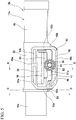
- the steering column 4a is installable on the vehicle body 15a with an upper bracket (a support bracket) 17a.
- the outer column 11a is supported with respect to the upper bracket 17a to be able to be moved in the forward and rearward direction.
- the support bracket 17a is supported on the vehicle body 15a through a locking capsule 18a to be able to be detached (drop out) when receiving a strong impact.
- the "axial direction” is assumed to correspond to an axial direction of the steering shaft 2a or the axial direction of the outer column 11a when there is no special mention.
- one end of the inner column 10a is supported on the vehicle body 15a by the lower bracket 14a through the gear housing 12a.
- the lower bracket 14a supports the gear housing 12a to be able to freely rock about a tilt shaft 16a disposed in a width direction (to be substantially parallel to the width direction).
- the steering column 4a is supported on the vehicle body 15a in a manner displaceable by rocking using the tilt shaft 16a installed in the width direction as a center.
- the outer column 11a is supported on the upper bracket 17a to be movable in a vertical direction.
- the "width direction” is assumed to correspond to a width direction of the vehicle body in which the steering device is installed when there is no special mention.
- the "vertical direction” is assumed to correspond to a vertical direction of the vehicle body in which the steering device is installed.
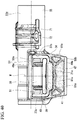
- a basic constitution of the steering device in this example is as described above. Next, a constitution of the outer column 11a and peripheral parts thereof will be described in detail.
- the outer column 11a is configured by coupling a frame body (a main body part and a sandwiched portion main body) 34 made of a light alloy, such as an aluminum-based alloy and a magnesium-based alloy, and a cylindrical body (a cylindrical member) 35 made of an iron-based alloy such as a carbon steel plate in the axial direction.
- the outer column 11a is made of a light alloy such as an aluminum-based alloy and a magnesium-based alloy, and can be configured such that the frame body (the main body part and the sandwiched portion main body) 34 disposed at a first half thereof and the cylindrical body (the cylindrical member) 35 disposed at a second half thereof are arranged in the axial direction and integrally coupled to each other.
- the outer column 11a can have other materials and/or other constitutions.
- the frame body 34 is movably supported on the upper bracket 17a in the forward and rearward direction and the vertical direction.
- An axial slit 36 (a first slit) extending in the axial direction is formed in a lower surface of the frame body 34.
- a front end section of the axial slit 36 is open in a front end surface of the frame body 34.
- circumferential slits 37a and 37b extending in a circumferential direction are formed in a portion near a front end of the frame body 34 and a portion near a rear end thereof in a lower half thereof.
- the circumferential slit 37a at a front side of the frame body 34 is formed to intersect a portion near a front end of the axial slit 36 in the circumferential direction.
- the circumferential slit 37b at a rear side of the frame body 34 is formed to intersect a portion near a rear end of the axial slit 36 in the circumferential direction.
- Clamp parts 38 and 38 are formed to enclose both sides of the frame body 34 in the width direction using the axial slit 36, the circumferential slit 37a, and the circumferential slit 37b in three directions.
- a non-fixed end is continuously formed at least on two lateral sides, which are arranged to be spaced apart from each other in the axial direction, and on one side in a first direction intersecting the axial direction (a first intersecting direction; a substantially vertical direction in this example).
- the other side of the clamp part 38 in the first direction is a fixed end.
- the clamp part 38 has a cantilever structure with the fixed end extending in the axial direction.
- the clamp part 38 is lower in rigidity in at least the width direction than other portions of the frame body 34 and is elastically deformable in the width direction (an inner diameter thereof is elastically expandable and contractable).
- each of the clamp parts 38 and 38 has an inner circumferential surface with a partial cylindrical surface shape.
- the clamp parts 38 and 38 are provided adjacent to both sides of the axial slit 36 in the circumferential direction.
- the clamp parts 38 and 38 have a shape in which the clamp parts extend in the axial direction and the circumferential direction (or the first direction).
- Plate-like projecting plates (projecting parts) 39 and 39 are provided on intermediate portions in the first direction (the substantially vertical direction in this example) of outer surfaces of the clamp parts 38 and 38 in the width direction in a state in which the projecting plates protrude outwardly in the width direction.
- Acting surfaces (third surfaces, third acting surfaces, and pressed surfaces) 40 and 40 receiving a tightening force of the tightening mechanism 80 are formed on lower end sections (portions lower than the projecting plates 39 and 39) of the outer surfaces of the clamp parts 38 and 38 in the width direction.
- the acting surface 40 has a flat surface shape. Additionally and/or alternatively, the acting surface 40 can have a shape other than a flat shape.
- the first direction intersects the width direction of the vehicle body and is orthogonal to the axial direction.
- the first direction can substantially correspond to the circumferential direction of the outer column 11a.
- the first direction can intersect the axial direction in a different direction from the direction orthogonal to the axial direction.
- a second direction is assumed to be a direction intersecting the axial direction and the first direction.
- a substantial tightening direction of the tightening mechanism 80 may coincide with the second direction.
- the second direction substantially coincides with the width direction of the vehicle body.
- the second direction can include directions other than the width direction of the vehicle body.
- the outer column 11a includes a reinforcing bridge part (a reinforcing part, a reinforcing structure, and a reinforcing member) 41 bridged between both sides of the outer column 11a in the second direction (substantially in the width direction of the vehicle body in this example).
- the reinforcing bridge part 41 is provided to extend to be substantially continuous between both sides of the outer column 11a in the second direction, and to physically join both sides of the outer column 11a in the second direction.
- the reinforcing bridge part 41 is provided on a lower portion of the frame body 34 to cover the clamp parts 38 and 38 from below.
- the reinforcing bridge part 41 is integrally formed with the outer column 11a.
- the reinforcing bridge part 41 includes a reinforcing plate 42 and a pair of joining parts 43a and 43b.
- a shape of the reinforcing bridge part 41 viewed from the width direction is a substantially U shape (an angulated U shape).
- the reinforcing plate 42 is disposed below the clamp parts 38 and 38 and is provided to extend in the width direction and the forward and rearward direction.
- the reinforcing plate 42 includes a flat plate (a central flat plate) 44 disposed at a center of the reinforcing plate in the width direction and outer flat plates (lower extension parts) 45 and 45 disposed on both sides of the reinforcing plate in the width direction and below the flat plate 44.
- the flat plate 44 and the outer flat plate 45 are provided to be continuous through a step part 46.
- the reinforcing bridge part 41 has a crank-shaped cross section.
- the joining part 43a disposed relatively forward is provided to extend upward from portions (the outer flat plates 45 and 45) on both sides of a front end section of the reinforcing plate 42 in the width direction.
- the joining part 43a is joined to portions of a lower surface of a front end section of the frame body 34 which are adjacent to a front side of the circumferential slit 37a and are on both sides which surround the axial slit 36 in the circumferential direction.
- the joining part 43b disposed at the rear side of the reinforcing bridge part 41 is provided to extend upward from a rear end section of the reinforcing plate 42.
- the joining part 43b is joined to a portion of a lower surface of a rear end section of the frame body 34 which is adjacent to a rear side of a rear end section of the axial slit 36.
- the reinforcing bridge part 41 can have a different constitution from the above.
- the outer column 11a includes the above-described reinforcing bridge part 41 to have high twisting rigidity.
- Gaps (slits) 47 and 47 with a substantially U shape (a substantially angulated U shape) when viewed from the width direction (the second direction) are provided between the reinforcing bridge part 41 and the clamp parts 38 and 38.
- the gaps 47 and 47 have at least telescopic adjustment slots (first through holes, axial slits, and first slits) 21a and 21a extending in the axial direction (the axial direction of the outer column 11a and the axial direction of the steering shaft 2a) and the circumferential slits (second slits) 37a and 37b provided to be continuous in the slots 21a and 21a and extending in a direction which intersects the slots 21a and 21a.
- the clamp parts 38 and 38 are provided adjacent to the slots 21a and 21a.
- the slots 21a and 21a form spaces which are present between distal end sections (lower end sections) of the clamp parts 38 and 38 and upper surfaces of portions on both sides of the flat plate 44 in the reinforcing plate 42 in the width direction.
- An adjusting rod 24a is inserted through the slots 21a and 21a in the width direction (the second direction).
- Roller travel depressed grooves 48 and 48 are provided in portions on both sides of the outer column 11a in the width direction in the axial direction of the slots 21a and 21a.
- the grooves 48 and 48 are provided in outer portions of the slots 21a and 21a in the width direction.
- the grooves 48 and 48 are enclosed in three directions by lower surfaces of the projecting plates 39 and 39 provided on the clamp parts 38 and 38, upper surfaces of the outer flat plates 45 and 45 of the reinforcing plate 42, outer surfaces (the acting surfaces 40 and 40) of distal end sections of the clamp parts 38 and 38 in the width direction, and outer surfaces of the step parts 46 and 46 of the reinforcing plate 42 in the width direction.
- the grooves 48 and 48 include the lower surfaces of the projecting plates 39 and 39 as first lateral wall surfaces, the upper surfaces of the outer flat plates 45 and 45 as second lateral wall surfaces, the acting surfaces 40 and 40 of the clamp parts 38 and 38 as first bottom surfaces, and the outer surfaces of the step parts 46 and 46 as second bottom surfaces.
- the outer column 11a has an acting surface (a first surface, a first acting surface, a first abutting surface, and a torque transmission surface) 49a and an acting surface (a second surface, a second acting surface, a second abutting surface, and a torque transmission surface) 49b which are provided on two lateral surfaces in the width direction.
- the acting surface 49a and the acting surface 49b are arranged to be spaced apart from each other in the first direction (the first intersecting direction) serving as a direction which intersects the axial direction (the axial direction of the outer column 11a and the axial direction of the steering shaft 2a).
- the clamp part 38 (and the acting surface 40) is arranged between the acting surface 49a and the acting surface 49b in the first direction.
- the adjusting rod 24a is arranged between the acting surface 49a and the acting surface 49b in the first direction
- the acting surface 40 of the clamp part 38 is arranged between the acting surface 49a and the adjusting rod 24a in the first direction.
- the axial slit 36 (the slot 21a) is arranged between the acting surface 49a and the acting surface 49b in the first direction.
- torque (a force in a twist direction) acting on the outer column 11a may be transmitted to inner surfaces of support plates 22a and 22a in the upper bracket 17a via the acting surface 49a and the acting surface 49b.
- the acting surface 49a is arranged within a range of an external form of the inner column 10a in the first direction.
- the acting surface 49b is arranged outside of the range of the external form of the inner column 10a in the first direction.
- the acting surface 49b is arranged outside of a range of an external form of the cylindrical body 35 of the outer column 11a.
- the acting surface 49a is arranged relatively closer to a central axis of the inner column 10a in the first direction, and the acting surface 49b is arranged relatively far from the central axis of the inner column 10a.
- Ridge parts 50 and 50 are provided on a portion near a central axis of the outer column 11a in the first direction (or the vertical direction) on both sides of the outer column 11a (the frame body 34) in the width direction to protrude outwardly in the width direction (the second direction).
- the ridge part 50 is provided to extend in the axial direction of the outer column 11 a.
- the acting surfaces 49a and 49a are provided on distal ends of the ridge parts 50 and 50 (outer surfaces thereof in the width direction).
- depressed portions 51a and 51b which are depressed in the width direction are provided in portions (front sections and rear sections) on both sides of the ridge parts 50 and 50 in the forward and rearward direction.
- the acting surfaces 49a and 49a have a shape in which two linear portions extending in the axial direction are joined to the front and rear end sections on both sides of the ridge parts 50 and intermediate portions thereof.
- the acting surface 49b on a lower side of the outer column 11a is provided on a distal end of the reinforcing plate 42 (the outer flat plates 45 and 45) (a lateral surface thereof in the width direction).
- Both of the acting surfaces 49a and 49b have a shape in which the acting surfaces 49a and 49b extend in the axial direction of the outer column 11a, and the acting surfaces 49a and 49b have a length longer in the axial direction than that of the clamp part 38.
- the acting surface 49a and the acting surface 49b have flat surface shapes. Additionally and/or alternatively, the acting surface 49a and the acting surface 49b can have shapes other than flat shapes.
- the acting surfaces 49a and 49b have rigidity higher in the width direction (the second direction) than those of the clamp parts 38 and 38.
- the acting surfaces 49a and 49b and the continuous surfaces 52a and 52b are located on the same virtual plane and are located slightly closer to outer sides of the projecting plates 39 and 39 in the width direction than end surfaces of the projecting plates 39 and 39 in the width direction.
- a locking depressed groove 53 extending in the circumferential direction is formed in an inner circumferential surface of a front end section of the outer column 11a (the frame body 34).
- a slide member 54 which is made of a synthetic resin with excellent slidability such as a polyamide resin, a polyacetal resin, and a polytetrafluoroethylene resin and having a whole shape in a substantially C shape, is attached in the locking groove 53 and the axial slit 36.
- the slide member 54 can include other materials and/or other constitutions.
- the slide member 54 includes a slide part main body 55 and a pair of support arms 56 and 56 with a partial circular arc shape extending from both sides of the slide part main body 55 in the width direction.
- the slide part main body 55 is disposed in the axial slit 36.
- the support arms 56 and 56 are disposed in the locking groove 53.
- an upper surface of the slide part main body 55 and an inner circumferential surface of the frame body 34 are located on the same imaginary cylindrical surface or slightly protrudes inward therefrom in a radial direction.
- a pair of depressed portions 57 and 57, which are depressed in the axial direction, are formed in the slide part main body 55.
- the two depressed portions 57 and 57 are arranged adjacent to each other in the width direction (the circumferential direction).
- the slide part main body 55 is set to have relatively low rigidity in the vertical direction.
- a pair of sandwiched plates are integrally formed with the outer column 11a in a state in which the axial slit 36 is sandwiched from both sides thereof in the width direction by the sandwiched plates, and distal end sections (lower end sections) of the sandwiched plates are joined to the outer column 11 a in the width direction in this example (by a portion corresponding to the reinforcing plate 42).
- outer surfaces of the sandwiched plates in the width direction are set as tightening surfaces with a substantially flat surface shape.
- the gaps (the slits) 47 and 47 with the substantially U shape and which communicate with an inner circumferential surface of the outer column 11a are formed in substantially central positions of the tightening surfaces, and portions enclosed by the gaps 47 and 47 are set as the clamp parts 38 and 38. Moreover, upper sides and lower sides of the tightening surfaces are set as the acting surfaces 49a and 49b.
- the upper bracket (the support bracket) 17a is made of, for example, a metal plate of steel, an aluminum-based alloy, or the like with sufficient rigidity.
- the upper bracket 17a includes an attachment plate 58 and the pair of the support plates 22a and 22a.
- the attachment plate 58 has an L-shaped cross section.
- the attachment plate 58 can have other materials and/or other shapes.
- the attachment plate 58 is normally supported on the vehicle body 15a.
- the attachment plate 58 is configured such that the attachment plate 58 is detached forward and a forward displacement of the outer column 11a is allowed on the basis of an impact such as a secondary collision.
- a pair of locking cutouts 59 and 59 are formed in a rear edge of the attachment plate 58 in an open state.
- the locking capsules 18a and 18a fixed to the vehicle body 15a using fixing members such as bolts or studs are locked into the locking cutouts 59 and 59.
- Locking grooves 60 and 60 configured to be engaged with right and left edge portions of the locking cutouts 59 and 59 are formed in right and left lateral surfaces of the locking capsules 18a and 18a, and through holes 61 and 61 through which both of the fixing members are inserted are formed in central portions of the locking capsules 18a and 18a.
- the support plates 22a and 22a are provided to hang from an attachment plate 55. Furthermore, the support plates 22a and 22a are provided to be parallel to each other in a state in which the front end section (the frame body 34 and the reinforcing bridge part 41) of the outer column 11a is sandwiched from both sides thereof in the width direction by the support plates 22a and 22a.
- the pair of support plates 22a and 22a are arranged on both of the sides of the outer column 11a in the width direction (the second direction).
- Tilt adjustment slots (second through holes) 23a and 23a extending in at least the vertical direction (the first direction) are formed in the support plates 22a and 22a.
- the slots 23a and 23a are provided in opposing positions (positions matching each other) in the width direction.
- the slots 23a and 23a are provided to match a portion of telescopic adjustment slots 21a and 21a in the forward and rearward direction.
- the slots 23a and 23a have long axes in the vertical direction (the first direction).
- the support plates 22a and 22a are arranged to be able to tighten the outer column 11a (the steering column 4a) using the tightening mechanism 80.
- the tightening mechanism 80 includes the adjusting rod 24a, an adjusting nut 25, an adjusting lever 26a, and the like.
- the adjusting rod 24a is inserted through the telescopic adjustment slots 21a and 21a and the tilt adjustment slots 23a and 23a in the width direction.
- the adjusting rod 24a includes an anchor part 27a disposed on one end section, a male screw part formed in the other end section, and a shaft part 62 formed on an intermediate portion in the width direction (the axial direction and the second direction of the adjusting rod 24a).
- a pair of rollers 63 and 63 are rotatably supported on the shaft part 62 in a state in which the rollers are spaced apart from each other in the width direction.
- the rollers 63 and 63 are constituted of, for example, roller bodies 64 and 64 made of a metal and collars 65 and 65 manufactured by an elastic material made of a synthetic resin such as a polyamide resin (nylon) and a polytetrafluoroethylene (PTFE) resin or rubber.
- the rollers 63 and 63 can include other materials and/or other constitutions.
- the roller bodies 64 and 64 have a substantially cylindrical shape, as shown in Figs. 18 to 20 .
- Through holes 66 and 66 through which the shaft part 62 is inserted are formed in central portions of the roller bodies 64 and 64.
- Flanges 67 and 67 with an outward flange shape are formed on end sections of outer circumferential surfaces of the roller bodies 64 and 64 in the width direction.
- Thin parts 68 and 68 with a circular arc cross section, which are depressed in the width direction, are formed on intermediate portions of the roller bodies 64 and 64 in a radial direction at a plurality of (four in the illustrated example) locations at equal circumferential intervals in the circumferential direction.
- the collars 65 and 65 have a cylindrical shape as shown in Figs. 21 to 23 .
- a thickness dimension of the collars 65 and 65 is larger than a height dimension of the flanges 67 and 67 in a radial direction.
- the collars 65 and 65 are press-fitted to (externally engaged with) portions of the outer circumferential surfaces of the roller bodies 64 and 64 which are deviated from the flanges 67 and 67 in the width direction.
- one long/elongated roller which is continuously elongated in the width direction can also be used in the width direction instead of a pair of rollers, or the whole roller can be made of a synthetic resin or rubber.
- Outer end surfaces of the rollers 63 and 63 in the width direction are located slightly closer to an outer side in the width direction than end surfaces of the projecting plates 39 and 39 in the width direction in a state in which the adjusting rod 24a is inserted through the telescopic adjustment slots 21a and 21a and the tilt adjustment slots 23a and 23a, and the rollers 63 and 63 are disposed in the roller travel grooves 48 and 48.
- the anchor part 27a is provided on one end side of the adjusting rod 24a in the width direction.
- the anchor part 27a is relatively non-rotatably engaged with the tilt adjustment slot 23a formed in one of the support plates 22a.
- a cam device 69 which is constituted of a driving-side cam and a driven-side cam, and the adjusting lever 26a are provided in the vicinity of a portion of the adjusting rod 24a (the shaft part 62) which protrudes in the width direction from an outer surface of the other support plate 22a in the width direction.
- a nut 70 is screwed on the male screw part.
- the driving-side cam of the cam device 69 is rotated relative to the driven-side cam on the basis of a rocking operation of the adjusting lever 26a in the tightening mechanism 80 so that a width dimension (a dimension of the adjusting rod 24a in the axial direction) of the cam device 69 is expandable and contractable.
- a tilt spring (a tilt flip-up spring or a balance spring) 72A serving as a coil spring is provided in the attachment plate 58 in the upper bracket 17a.
- the tilt spring 72A is bridged between a bent part 71A provided on a front end section in the attachment plate 58 and the cam device 69 (the driven-side cam).
- An upward biasing force is exerted on the adjusting rod 24a via the cam device 69 using the tilt spring 72A.
- the biasing force exerted on the adjusting rod 24a is transmitted to the lower surfaces of the projecting plates 39 and 39 constituting upper sides of the roller travel grooves 48 and 48 via the rollers 63 and 63, and thus the outer column 11a is pressed upward.
- the steering device includes a steering lock device serving as a type of a vehicle anti-theft device.
- a locking through hole 33a is formed to pass through a portion of the outer column 11a near a front end of the cylindrical body 35 in a radial direction.
- a lock unit 73 is supported by and fixed to the vicinity of the locking through hole 33a, and a key lock collar 74 is externally-fitted (press-fitted) to the steering shaft 2a.
- the key lock collar 74 is arranged at a portion at which phases of the key lock collar 74 and the lock unit 73 coincide with each other at a part of the steering shaft 2a in the axial direction.
- a distal end section of a lock pin 75 is displaced toward an inner diameter of the outer column 11a and is engaged with a key lock depressed portion 76 formed in an outer circumferential surface of the key lock collar 74.
- the steering shaft 2a cannot be substantially rotated. That is to say, the key lock depressed portion 76 is engaged with the distal end section of the lock pin 75 in a state in which the steering shaft 2a cannot be substantially rotated at a time of key locking.
- a predetermined value for example, a value defined by key lock regulations; a limit value used to release a non-rotatable state is set for the lock unit 73.
- the tightening mechanism 80 has a first state (a first form and a first mode) in which the outer column 11a (the steering column 4a) is tightened through an upper bracket (a support bracket) 17a, and a second state (a second form and a second mode) in which the tightening is released.
- the adjusting lever 26a of the tightening mechanism 80 is rocked (turned) about the adjusting rod 24a in a predetermined direction (generally, upward).
- a width dimension of the cam device 69 increases, and an interval between the inner surfaces of the support plates 22a and 22a decreases.
- the rollers 63 and 63 are pressed inward in the width direction by the inner surfaces of the support plates 22a and 22a.
- the acting surfaces 40 and 40 bottom surfaces of the roller travel grooves 48 and 48 formed on the lower end sections (the distal end sections) of the clamp parts 38 and 38 are pressed by inner surfaces of the rollers 63 and 63 in the width direction.
- the clamp parts 38 and 38 are bent (elastically deformed) inwardly in the width direction (toward an axial center), and an outer circumferential surface of the inner column 10a is elastically sandwiched (held) using the clamps 38 and 38 (is tightened in the tightening direction (the second direction)).
- the steering wheel 1 is held in the adjusted position.
- the acting surfaces 49a and 49b and the flat continuous surfaces 52a and 52b are pressed inwardly in the width direction by the inner surfaces of the support plates 22a and 22a.
- the outer column 11a is sandwiched from both sides of the outer column 11a in the width direction by the inner surfaces of the support plates 22a and 22a through the acting surfaces 49a and 49b (is tightened in the tightening direction (the second direction)).
- the adjusting lever 26a is rocked (turned) in an opposite direction (generally, downward) to the predetermined direction.
- the width dimension of the cam device 69 decreases and the interval between the inner surfaces of both of the support plates 22a and 22a increases. Since a pressing force on the rollers 63 and 63 by the support plates 22a and 22a decreases, a width dimension between the clamp parts 38 and 38 elastically increases and a holding force of the outer circumferential surface of the inner column 10a decreases (the tightening is released).
- the front and rear position and the vertical position of the steering wheel 1 can be adjusted in a range in which the adjusting rod 24a can be moved within the telescopic adjustment slots 21a and 21a and the tilt adjustment slots 23a and 23a.
- the acting surfaces 49a and 49a, the acting surfaces 49b and 49b, and the acting surfaces 40 and 40 of the clamp parts 38 and 38 are provided on both of the sides of the outer column 11a in the width direction (the second direction and the tightening direction).
- the acting surfaces 49a and 49a and the acting surfaces 49b and 49b are directly pressed onto the support plates 22a and 22a of the upper bracket 17a in the tightened state (the first state).
- the acting surfaces 40 and 40 of the clamp parts 38 and 38 are indirectly pressed onto the support plates 22a and 22a through the rollers 63 and 63 in the tightened state (the first state).
- the acting surface (the first surface) 49a, the acting surface (the second surface) 49b, and the acting surface (the third surface) 40 are substantially independent of each other.
- the acting surfaces 49a and 49a and the acting surfaces 49b and 49b are provided on the frame body 34 of the outer column 11a, and positions thereof with respect to the inner column 10a do not substantially change, or amounts of displacement thereof are slight while transitioning from the released state (the second state) to the tightened state (the first state).
- a position of the acting surface 40 of the clamp part 38 with respect to the inner column 10a changes with a relatively large amount of displacement (is displaced toward the inner column 10a) (a displacement surface) while transitioning from the released state (the second state) to the tightened state (the first state).
- the outer column 11a and the support plates 22a and 22a are coupled to each other by a force acting on the acting surfaces 49a and 49a mainly at a position near the central axis of the outer column 11a.
- the outer column 11a and the support plates 22a and 22b are coupled to each other by a force acting on the acting surfaces 49b and 49b mainly at a position away from the central axis of the outer column 11a.
- the inner column 10a is held mainly in the outer column 11a through the clamp part 38 by a force acting on the acting surfaces 40 and 40. Therefore, in the steering device in this example, securing strength of the outer column 11a and securing a holding force of the inner column 10a are simultaneously and independently realized, and a position adjusting mechanism with high stability is provided.
- Fig. 46 and Fig. 47 illustrate the conventional steering device disclosed in Patent Literature 1.
- a front and rear position and a vertical position of a steering wheel 1 needs to be able to be adjusted, and an outer column 11 is movably supported on an upper bracket 17 in a forward and rearward direction and a vertical direction.
- a slit 19 extending in an axial direction of the outer column 11 is formed in a lower surface of a front end section of the outer column 11.
- a pair of clamp parts 20 and 20 are integrally formed with the outer column 11 in a state in which the slit 19 is sandwiched from both sides thereof in a width direction by the clamp parts 20 and 20.
- telescopic adjustment slots 21 and 21 which are elongated in the forward and rearward direction, are formed at positions in which the clamp parts 20 and 20 are mutually matched.
- a pair of support plates 22 and 22 are provided in the upper bracket 17 in a state in which the clamp parts 20 and 20 are sandwiched from both sides thereof in the width direction by support plates 22 and 22.
- Tilt adjustment slots 23 and 23 which are elongated in the vertical direction, are formed in portions at which the support plates 22 and 22 partially match and which partially match the telescopic adjustment slots 21 and 21 in the forward and rearward direction.
- An adjusting rod 24 is inserted through the telescopic adjustment slots 21 and 21 and the tilt adjustment slots 23 and 23 in the width direction (the right to the left of Fig.
- the adjusting nut 25 is screwed on another end of the adjusting rod 24.
- the adjusting nut 25 can be rotated through an adjusting lever 26.
- the adjusting nut 25 is rotated on the basis of an operation of the adjusting lever 26.
- the outer column 11 is fixed to the upper bracket 17 or the fixing is released along with a change in an interval between the adjusting nut 25, the anchor part 27, and the adjusting rod 24.
- the outer column 11 is fixed to an inner column 10 or the fixing is released along with an interval between the clamp parts 20 and 20.
- the adjusting rod 24 can be displaced inside the telescopic adjustment slots 21 and 21 in the forward and rearward direction in a state in which an interval between the adjusting nut 25 and the anchor part 27 increases.
- the outer column 11 is moved forward and rearward (is displaced relative to the inner column 10) in such a displaceable range (a telescopic adjustment range) so that the front and rear position of the steering wheel 1 can be adjusted.
- the adjusting rod 24 can be displaced inside the tilt adjustment slots 23 and 23 in a substantially vertical direction.
- the vertical position of the steering wheel 1 can be adjusted in such a displaceable range (a tilt adjustment range).
- a steering column 4 is rocked and displaced about a tilt shaft 16 in the vertical direction.
- a front end section of an output shaft 13 in a steering force auxiliary device 5 is joined to a rear end section of an intermediate shaft 29 through a universal joint 28.
- An input shaft 31 of a steering gear unit 7 is joined to a front end section of the intermediate shaft 29 through another universal joint 30.
- the steering gear unit 7 includes a rack and a pinion (which are not shown), and the input shaft 31 is coupled to the pinion. Both end sections of the rack meshed with the pinion are joined to tie rods 6 and 6.
- the tie rods 6 and 6 are pushed and pulled on the basis of a displacement of the rack in the axial direction so that a desired steering angle is given to a steering wheel 3 (refer to Fig. 45 ).
- the steering force auxiliary device 5 can give auxiliary torque at a predetermined size in a predetermined direction to the output shaft 13 through a worm speed reducer using an electric motor 32.
- a contact state of a contact portion which is in a portion X indicated by a circle in Fig. 48 , of an upper end section of a rear edge of the inner column 10 and an inner circumferential surface of the outer column 11 is a line contact.
- a contact state of a contact portion which is in a portion Y indicated by a circle in Fig. 48 , of a lower end section of a front edge of the outer column 11 and an outer circumferential surface of the inner column 10 is a line contact.
- This phenomenon reduces an operational feeling of adjusting the front and rear position of the steering wheel 1 and causes an operational load in the forward and rearward direction to increase.
- a column type electric power steering device (a column type electric power steering (EPS) device) in which the steering force auxiliary device 5 is combined with a steering column 2 like in the illustrated structure
- EPS electric power steering
- a fit length of the inner column 10 and the outer column 11 is set to be relatively short due to restrictions on an installation space of the steering column 4.
- an angle of inclination of the outer column 11 easily increases, and thus the above-described problem easily occurs.
- a new problem occurs in that processing costs increase due to precision machining such as a task of reducing a gap between an outer column and an inner column and chamfering performed on an outer circumferential edge of an end section of the inner column.
- the adjusting rod 24a is biased upward by the tilt spring 72A.
- a biasing force F1 is transmitted to the front end section (the frame body 34) of the outer column 11a via the rollers 63 and 63.
- the outer column 11a is pressed upward by the biasing force F1 even when a force F2 in a direction which presses the rear end section of the outer column 11a downward is applied to a rear end section of the outer column 11a on the basis of the weight of the steering wheel 1.
- a slope of the outer column 11 a is zero or can be reduced (the rear end section can be prevented from being tilted downward).
- a gap is secured between an upper end section of the inner circumferential surface of the outer column 11a and an upper end section of the outer circumferential surface of the inner column 10a. Therefore, an upper end section in a rear edge of the inner column 10a comes more firmly into line contact with the inner circumferential surface of the outer column 11a. For this reason, the occurrence of catching (twisting) when the front and rear position of the steering wheel 1 is adjusted can be effectively prevented.
- the biasing force exerted on the adjusting rod 24a is transmitted to the outer column 11a (the lower surfaces of the projecting plates 39 and 39) via the rollers 63 and 63.
- the rollers 63 and 63 travel (roll) along the lower surfaces of the projecting plates 39 and 39. Frictional resistance generated when the outer column 11a is displaced relative to the inner column 10a in the forward and rearward direction is suppressed to be small compared to when the outer column is directly biased by the adjusting rod.
- a sleeve or the like made of a resin is used for a sliding contact portion between the adjusting rod and the outer column to secure slidability so that sliding resistance can be reduced.
- a surface pressure increases, and a problem easily occurs in terms of durability because the outer circumferential surface of the adjusting rod comes into line contact with the sleeve.
- a rolling contact is used, and thus such a problem is avoided.
- the collars 65 and 65 made of a synthetic resin are used as outer circumferential surfaces of the rollers 63 and 63, and thus sliding based on contact between metals is avoided and the rollers 63 and 63 can be effectively rotated.
- the biasing force is exerted on the adjusting rod 24a through the tilt spring 72A, the biasing force is exerted on a whole region of the steering wheel 1 in a forward and rearward adjustment range.
- the front and rear position of the steering wheel 1 is smoothly adjusted in a state in which the rollers 63 and 63 are sandwiched so that the biasing force is exerted upward.
- the slide part main body 55 is provided on a lower end section of a front edge of the outer column 11a (the frame body 34), an upper surface of the slide part main body 55 is in contact with an outer circumferential surface of the inner column 11a.
- a contact form of a lower end section of a front edge of the outer column 11a and the outer circumferential surface of the inner column 10a is prevented from becoming a line contact. Therefore, catching at such a portion is suppressed to be small, and thus sliding resistance can be prevented from being excessively increased at a time of front and rear position adjustment.
- the steering device in this example can be preferably applied even when the total length of the steering column 4a is relatively short. That is to say, the catching (the twisting) at the time of adjusting the front and rear position of the steering wheel 1 is prevented even when a constitution of the column EPS has been adopted, and a high operation feeling is obtained at the time of adjusting the front and rear position of the steering wheel 1, and thus an operational load is suppressed to be small low.
- the anti-theft steering lock device disclosed in Patent Literature 2 is incorporated in some cases. In this case, a problem is likely to occur in terms of securing durability of the outer column 11.
- the steering lock device is constituted by mounting the lock unit (a key lock cylinder) around a locking through hole 33 partially formed in the outer column 11 and the key lock collar on a part of the steering shaft 2. In a state in which the ignition key is pulled out, a key lock pin provided in the lock unit is engaged with a key lock hole (a depressed portion) provided in the key lock collar, and thus rotation of the steering shaft 2 with respect to the outer column 10 can be prevented.
- the acting surface 40 of the clamp part 38 and the acting surfaces 49a and 49b are separately provided on both of the sides of the outer column 11a in the width direction.
- the clamp parts 38 and 38 are used for elastically sandwiching the outer circumferential surface of the inner column 10a.
- the torque acting on the outer column 11a is transmitted to the inner surfaces of the support plates 22a and 22a of the upper bracket 17a via the acting surfaces 49a and 49b.
- the clamp parts 38 and 38 may be adopted as long as the clamp parts 38 and 38 can exhibit only a function of sandwiching the inner column 10a.
- the steering device in this example desired bending characteristics such as greatly bending the clamp parts 38 and 38 in the width direction can be set for the clamp parts 38 and 38.
- the acting surfaces 49a and 49b may be adopted as long as the acting surfaces 49a and 49b can exhibit only a function of transmitting the torque. For this reason, it is not necessary to greatly bend sections in which the acting surfaces 49a and 49b in the outer column 11a are installed in the width direction. Therefore, according to the steering device in this example, securing the strength of the outer column 11a can be independently compatible with securing the holding force of the inner column 10a.
- the inner surfaces of the support plates 22a and 22a are brought into contact with (pressed by) the acting surfaces 49a and 49b to hold the steering wheel 1 at the desired position.
- the clamp parts 38 and 38 are bent through the inner surfaces of the support plates 22a and 22a.
- the acting surfaces 49a and 49b are substantially independent from the acting surface 40 of the clamp part 38, and the portions in which the acting surfaces 49a and 49b are installed have sufficiently high rigidity (bending rigidity and bent characteristics) compared to the clamp part 38.
- the acting surface 49a and the acting surface 49b are arranged to be spaced apart from each other in the first direction which intersects the second direction (the tightening direction).
- a position of the acting surface 49b is outside of the range of the external form of the inner column 10a in the first direction, and is outside of a range of the external form of the cylindrical body 35 of the outer column 11a. For this reason, the torque acting on the outer column 11a is absorbed through the acting surfaces 49a and 49b, and thus the torque can be prevented from being transmitted to the clamp part 38.
- FIG. 26 A second example according to an embodiment of the present invention will be described with reference to Fig. 26 and Fig. 27 .
- shapes of clamp parts 38a and 38a configured to elastically surround an outer circumferential surface of an inner column 10a in a steering device in this example are different from those of the above-described first example according to an embodiment.
- constituent parts which are the same as or equivalent to those of the above-described will be denoted with the same reference numerals, and a description thereof will be simplified or omitted.
- cross-sectional shapes of the clamp parts 38a and 38a associated with a virtual plane orthogonal to a central axis O 11 of an outer column 11b have symmetrical shapes with respect to a virtual line V passing through the central axis O 11 of the outer column 11b and orthogonal to a central axis O 21 of slots (slits) 21b and 21b between the clamp parts 38a and 38a.
- the cross-sectional shapes of the clamp parts 38a and 38a are constant (has a symmetrical shape in a forward and rearward direction) over an entire length in an axial direction.
- the clamp part 38a has a substantially symmetrical shape and symmetrical structure with respect to a symmetry axis along a first direction that intersects the axial direction.
- an acting surface 40 of the clamp part 38a has a substantially symmetrical shape with respect to the symmetry axis.
- a center of the acting surface 40 in the axial direction is located on the symmetry axis.
- centers of an acting surface 49c and an acting surface 49d of an outer column 11a in the axial direction coincide with a center of the clamp part 38a.
- the centers of the acting surface 49c and the acting surface 49d in the axial direction coincide with the center of the acting surface 40 of the clamp part 38a.
- a center of a telescopic adjustment slot 21a in the axial direction coincides with the centers of the acting surface 49c, the acting surface 49d, and the acting surface 40.
- circumferential slits 37c and 37d extending linearly in a circumferential direction are formed in a frame body 34a of the outer column 11b.
- the circumferential slits 37c and 37d are provided to intersect portions near front and rear ends of an axial slit 36 formed in a lower surface of the frame body 34a in the circumferential direction.
- the clamp part 38a enclosed in three directions by the axial slit 36, the circumferential slit 37c, and the circumferential slit 37d is formed on portions near both sides of the frame body 34a in a width direction.
- a gap 47a (a slit) is formed between the clamp part 38a and a reinforcing bridge part 41.
- a shape of the gap 47a viewed from the width direction is a substantially U shape (a substantially angulated U shape) in which front and rear end sections thereof are bent at right angles.
- Torque acting on the outer column 11b is transmitted to inner surfaces of support plates 22a and 22a of an upper bracket 17a (refer to Fig. 2 and the like) through the acting surfaces 49c and 49d.
- the acting surfaces 49c and 49d have a symmetrical shape in the forward and rearward direction.
- the acting surfaces 49c and 49d and continuous flat surfaces 52a and 52b are continuous in rectangular (quadrangular) frame shapes.
- the clamp parts 38a and 38a are bent using the inner surfaces of the support plates 22a and 22a such that a steering wheel 1 (refer to Fig. 46 ) is held at a desired position. At this time, concentration of stress on a part of the clamp parts 38a and 38a is prevented clamp part regardless of a front and rear position of an adjusting rod 24a (refer to Fig. 2 ) in telescopic adjustment slots 21b and 21b.
- the telescopic adjustment slots 21b and 21b can be designed such that a dimension thereof in the forward and rearward direction is larger than that of the case of the above-described first example. In this case, an adjustment length in the forward and rearward direction of the steering wheel 1 increases. Other constitutions and operational effects are the same as those of the case of the first example.
- clamp parts 38a and 38a in a steering device in this example are different from those of the above-described first example according to the embodiment.
- projecting plates (projecting parts) 39 and 39 are provided on lower end sections of outer surfaces of the clamp parts 38 and 38 in a width direction in a state in which the projecting plates (projecting parts) 39 and 39 protrude outward in the width direction (a second direction).
- Acting surfaces (a third surface, a third acting surface, and a pressed surface) 40 and 40 are formed outside the projecting plates 39 and 39 in the width direction (the second direction).
- the acting surface 40 has a flat surface shape. Additionally and/or alternatively, the acting surface 40 can have a shape other than a flat shape.
- Reinforcing ribs 51 and 51 are provided between upper surfaces (lateral surfaces of walls) of the projecting plate 39 and 39 and cylindrical-surface-shaped upper end sections or intermediate portions of outer surfaces of the clamp parts 38 and 38 in the width direction.
- the plurality of reinforcing ribs 51 (an example in which five reinforcing ribs 51 is in the drawing) are provided to extend in the width direction and are disposed to be spaced apart from each other in a forward and rearward direction (an axial direction).
- An outer column 11a includes a reinforcing bridge part (a reinforcing part, a reinforcing structure, and a reinforcing member) 41 bridged between both sides of the outer column 11a in the width direction (the second direction).
- the reinforcing bridge part 41 is provided to extend to be substantially continuous between both of the sides of the outer column 11a in the width direction (the second direction) and to physically join both of the sides of the outer column 11a in the width direction (the second direction).
- the reinforcing bridge part 41 is provided at a lower portion of a frame body 34 in a state in which the reinforcing bridge part 41 covers the clamp parts 38 and 38 from below.
- the reinforcing bridge part 41 is integrally formed with the outer column 11a.
- the reinforcing bridge part 41 includes a reinforcing plate 42 and a pair of joining parts 43a and 43b.
- a shape of the reinforcing bridge part 41 viewed from the width direction is substantially a U shape (an angulated U shape).
- the reinforcing plate 42 is disposed below the clamp parts 38 and 38, and is provided to extend in the width direction and the forward and rearward direction.
- the reinforcing plate 42 includes a flat plate 44 disposed parallel to a central axis of the outer column 11a and a pair of downward extending parts 45 and 45 provided to extend downward from a lower surface of both end sections of the flat plate 44 in the width direction.
- the reinforcing plate 42 has a substantially angulated U shaped cross section.
- a cutout 46 passing in a vertical direction is formed in an intermediate portion of a front end section of the reinforcing plate 42 (the flat plate 44) in the width direction.
- a plurality of (three in the illustrated example) flat-plate-shaped reinforcing coupling plates 52 and 52 extending in the width direction are provided between a lower surface of an intermediate portion of the flat plate 44 in the width direction and inner surfaces of downward extending parts 45 and 45 in the width direction in a state in which the reinforcing coupling plates 52 and 52 are spaced apart in the forward and rearward direction.
- a joining part 43a disposed relatively forward is provided to extend upward from both sides (both sides of the cutout 46) of a front end section of the reinforcing plate 42 in the width direction.
- the joining part 43a is a portion of a lower surface of a front end section of the frame body 34 which is adjacent to a front side of a circumferential slit 37a, and is coupled to both side portions in the circumferential direction which surround the axial slit (a first slit) 36.
- a joining part 43b disposed relatively rearward is provided to extend upward from a rear end section of the reinforcing plate 42.
- the joining part 43b is coupled to a portion of a lower surface of a rear end section of the frame body 34 which is adjacent to a rear side of a rear end section of an axial slit 36.
- the reinforcing bridge part 41 can have a different constitution from the above.
- the outer column 11a includes the above-described reinforcing bridge part 41, and thus has high twist rigidity.
- Gaps (the slits) 47 and 47 with a substantially U shape (an angulated U shape) when viewed from the width direction (the second direction) are formed between the reinforcing bridge part 41 and the clamp parts 38 and 38.
- the gaps 47 and 47 have at least telescopic adjustment slots (axial slits, first slits, and first through holes) 21a and 21a extending in the axial direction (an axial direction of the outer column 11a and an axial direction of a steering shaft 2a) and circumferential slits (the second slits) 37a and 37b provided to be continuous with the slots 21a and 21a and extending in a direction such that intersect the slots 21a and 21a.
- the clamp parts 38 and 38 are provided adjacent to the slots 21a and 21a.
- the slots 21a and 21a form spaces which are present between distal end sections (lower end sections) of the clamp parts 38 and 38 and upper surfaces of the reinforcing plate 42 (the flat plate 44).
- An adjusting rod 24a is inserted through the slots 21a and 21a in the width direction (the second direction).
- the outer column 11a has an acting surface (a first surface, a first acting surface, a first abutting surface, and a torque transmission surface) 49a and an acting surface (a second surface, a second acting surface, a second abutting surface, and a torque transmission surface) 49b which are provided on two lateral surfaces thereof in the width direction.
- the acting surface 49a and the acting surface 49b are arranged to be spaced apart from each other in a first direction (a first intersecting direction) serving as a direction which intersects the axial direction (the axial direction of the outer column 11a and the axial direction of the steering shaft 2a).
- the clamp part 38 (and the acting surface 40) is arranged between the acting surface 49a and the acting surface 49b in the first direction.
- the adjusting rod 24a is arranged between the acting surface 49a and the acting surface 49b in the first direction
- the acting surface 40 of the clamp part 38 is arranged between the acting surface 49a and the adjusting rod 24a in the first direction.
- the axial slit 36 (the slot 21a) is arranged between the acting surface 49a and the acting surface 49b in the first direction.
- torque (a force in a twist direction) acting on the outer column 11a may be transmitted to inner surfaces of support plates 22a and 22a in an upper bracket 17a via the acting surface 49a and the acting surface 49b.
- the acting surface 49a is arranged within a range of an external form of an inner column 10a in the first direction.
- the acting surface 49b is arranged outside of the range of the external form of the inner column 10a in the first direction.
- the acting surface 49b is arranged outside of a range of an external form of a cylindrical body 35 of the outer column 11 a.
- the acting surface 49a is arranged relatively close to a central axis of the inner column 10a, and the acting surface 49b is arranged relatively away from the central axis of the inner column 10a.
- Ridge parts 50a and 50a are provided in a portion overlapping a central axis of the outer column 11a in the first direction (or the vertical direction) on portions on both sides of the outer column 11a (the frame body 34) in the width direction to protrude outwardly in the width direction (the second direction).
- the ridge part 50a is provided to extend to the outer column 11 a.
- the acting surfaces 49a and 49a are provided on distal ends (outer surfaces thereof in the width direction) of the ridge part 50a.
- Ridge parts 50b and 50b are provided on lower end sections of outer surfaces of the downward extending parts 45 and 45 in the width direction to protrude outwardly in the width direction (the second direction).
- the ridge part 50b is provided to extend in the axial direction of the outer column 11a.
- the acting surfaces 49b and 49b are provided on distal ends (outer surfaces in the width direction) of the ridge part 50b.
- both of the acting surfaces 49a and 49b have a shape extending in the axial direction of the outer column 11a, and have a longer length than that of the clamp part 38 in the axial direction.
- the acting surface 49a and the acting surface 49b have a flat surface shape.
- the acting surface 49a and the acting surface 49b can have a shape other than the flat shape.
- the acting surfaces 49a and 49b have a higher rigidity in the width direction (the second direction) than those of the clamp parts 38 and 38.
- a plurality of (six in the illustrated example) depressed portions 53 and 53 which are depressed inwardly in the width direction are provided in intermediate portions in the vertical direction (above the ridge part 50b) on the outer surfaces of the downward extending parts 45 and 45 in the width direction in a state in which the depressed parts 53 and 53 are spaced apart from each other in the forward and rearward direction.
- the acting surface 49a, the acting surface 49b, and the acting surface 40 on one side in the width direction are located on the same virtual plane.
- the acting surface 49a, the acting surface 49b, and the acting surface 40 on the other side in the width direction are located on the same virtual plane.
- the acting surfaces 40 and 40 are arranged between the acting surfaces 49a and 49a and the acting surfaces 49b and 49b in the first direction.
- the acting surfaces 49a and 49a, the acting surfaces 49b and 49b, and the acting surfaces 40 and 40 can have a disposition relationship other than the above-described relationship.
- dimensions (X,Z) of the acting surfaces 49a and 49b disposed on the upper side and the lower side in the forward and rearward direction are larger than a dimension (Y) of the acting surface 40 in the forward and rearward direction (X > Y and Z > Y).
- the dimension (X) of the acting surface 49a in the forward and rearward direction is substantially the same as the dimension (Z) of the acting surface 49b in the forward and rearward direction (X ⁇ Z).
- a distance from a central portion of the telescopic adjustment slot 21a in the forward and rearward direction to a front edge of the acting surface 49a is set to be substantially the same as a distance from the central portion of the slot 21a in the forward and rearward direction to a rear edge of the acting surface 49a.
- the acting surface 40 of the clamp part 38 may substantially have a symmetrical shape with respect to a predetermined symmetry axis, and may by asymmetric with respect to the symmetry axis. Furthermore, in the axial direction, a center of the clamp part 38 (and/or the center of the acting surface 40) may coincide with and be offset from centers of the acting surface 49a and the acting surface 49b. A shape and/or a structure of the clamp part 38 may be set to be offset with respect to the acting surface 49a and the acting surface 49b in the axial direction. For example, the center of the clamp part 38 (and/or the center of the acting surface 40) can be located in front of (or behind) the centers of the acting surface 49a and the acting surface 49b of the outer column 11a.
- the center of the telescopic adjustment slot 21a may coincide with and be offset from at least one of the acting surface 49a, the acting surface 49b, and the acting surface 40.
- the center of the acting surface 40 in the clamp part 38 can be located in front of the center of the slot 21a.
- the acting surface 40 is offset in the axial direction so that it is possible to make the acting surface 40 change an operational force of an adjusting lever 26a even when front and rear positions of the steering wheel 1 have changed (refer to Figs. 45 and 46 ).
- the acting surface 40 tightens a rear-end-side portion of the inner column 10a.
- rigidity of the rear-end-side portion of the inner column 10a is lower than that of an intermediate portion thereof, a tightening reaction force thereof is relatively low, and the operational force of the adjusting lever 26a is relatively low.
- the acting surface 40 is offset forward so that the intermediate portion with a higher rigidity than that of the rear-end-side portion in the inner column 10a is pressed, and thus a high tightening reaction force is obtained.
- a change in rigidity of the inner column 10a along with a positional adjustment of the front and rear position is relatively small and a change in the tightening reaction force is also small in a state in which the steering wheel 1 is located relatively forward, and a fitting margin of the inner column 10a and the outer column 11a is large.
- a change in the operational force of the adjusting lever 26a along with a change in the front and rear position of the steering wheel 1 is minimized over the whole range due to the above-described offset.
- upper end sections of the joining parts 43a and 43b in the reinforcing bridge part 41 are continuous with both end sections of the ridge parts 50a and 50b in the forward and rearward direction.
- outer surfaces of the joining parts 43a and 43b in the width direction are located (offset) closer to insides in the width direction than the acting surface 49a, the acting surface 49b, and the acting surface 40.
- the inner surfaces of the support plates 22a and 22a in the upper bracket 17a can be set not to substantially come into contact with the outer surfaces of the joining parts 43a and 43b in the width direction.
- a pair of sandwiched plates are integrally formed with the outer column 11a in a state in which the axial slit 36 is sandwiched from both sides thereof in the width direction by the sandwiched plates, and distal end sections (lower end sections) of the sandwiched plates are joined to the outer column 11a in this example (by a portion corresponding to the reinforcing plate 42).
- outer surfaces of the sandwiched plates in the width direction are set as tightening surfaces with a substantially flat surface shape.
- the gaps (the slits) 47 and 47 with the substantially U shape which communicate with an inner circumferential surface of the outer column 11a are formed in substantially central positions of the tightening surfaces, and portions enclosed by the gaps 47 and 47 are set as the clamp parts 38 and 38. Moreover, upper sides and lower sides of the tightening surfaces are set as the acting surfaces 49a and 49b.
- the upper bracket (the support bracket) 17a is constituted of, for example, a metal plate of a steel-based alloy, an aluminum-based alloy, and the like with sufficient rigidity.
- the upper bracket 17a includes an attachment plate 58 and the pair of support plates 22a and 22a.
- the attachment plate 58 is normally supported on a vehicle body 15a.
- the attachment plate 58 is configured to be detached forward such that a forward displacement of the outer column 11a is allowed on the basis of an impact such as a secondary collision.
- a pair of locking cutouts 59 and 59 are formed in a rear edge of the attachment plate 58 in a state in which the locking cutouts 59 and 59 are open. Locking capsules 18a and 18a fixed to the vehicle body 15a using fixing members such as bolts or studs are locked into the locking cutouts 59 and 59.
- the support plates 22a and 22a are provided to hang from the attachment plate 58. Furthermore, the support plates 22a and 22a are provided to be parallel to each other in a state in which the front end section (the frame body 34 and the reinforcing bridge part 41) of the outer column 11a is sandwiched from both sides thereof in the width direction by the support plates 22a and 22a.
- the pair of support plates 22a and 22a are arranged on both sides of the outer column 11a in the width direction (the second direction).
- At least tilt adjustment slots (second through holes) 23a and 23a extending in the vertical direction (the first direction) are formed in the support plates 22a and 22a.
- the slots 23a and 23a are provided in opposing positions (positions matching each other) in the width direction.
- the slots 23a and 23a are provided to match portions of the telescopic adjustment slots 21a and 21a in the forward and rearward direction.
- the slots 23a and 23a have long axes in the vertical direction (the first direction).
- the support plates 22a and 22a are arranged to be able to tighten the outer column 11a (the steering column 4a) using a tightening mechanism 80.
- the tightening mechanism 80 includes the adjusting rod 24a, an adjusting nut 25, the adjusting lever 26a, and the like (refer to Fig. 28 ).
- the adjusting rod 24a is inserted through the telescopic adjustment slots 21a and 21a and the tilt adjustment slots 23a and 23a in the width direction.
- the adjusting rod 24a includes an anchor part disposed on one end section thereof, a male screw part formed at the other end section thereof, and a shaft part formed on an intermediate portion in the width direction (an axial direction of the adjusting rod 24a; the second direction).
- the adjusting rod 24a is disposed to be inserted through the telescopic adjustment slots 21a and 21a and the tilt adjustment the slots 23a and 23a.
- the anchor part is provided on one end side of the adjusting rod 24a in the width direction.
- the anchor part is relatively non-rotatably engaged with the tilt adjustment slot 23a formed in one support plate 22a.
- a cam device 69 which is constituted of a driving-side cam and a driven-side cam, and the adjusting lever 26a are provided in the vicinity of a portion of the adjusting rod 24a (the shaft part) which protrudes in the width direction from an outer surface of the other support plate 22a in the width direction.
- a nut 70 is screwed on the male screw part.
- the driving-side cam of the cam device 69 is rotated relative to the driven-side cam on the basis of a rocking operation of the adjusting lever 26a in the tightening mechanism 80 so that a width dimension (a dimension of the adjusting rod 24a in the axial direction) of the cam device 69 is expandable and contractable.
- the steering device includes a steering lock device serving as a type of a vehicle anti-theft device.
- a locking through hole 33a is formed in the cylindrical body 35 to pass through in a radial direction.
- a fixed part 71 configured to support and fix a lock unit (not shown) is provided on a portion in an outer circumferential surface of the cylindrical body 35 which is shifted from the locking through hole 33a in the circumferential direction.
- a pair of attachment flanges 72 and 72 are provided on the fixed part 71.
- the lock unit is supported by and fixed to the vicinity of the locking through hole 33a using the attachment flanges 72 and 72, and a key lock collar (not shown) is externally-fitted (press-fitted) to the steering shaft 2a.
- the key lock collar is arranged at a portion at which phases of the key lock collar and the lock unit coincide with each other at a part of the steering shaft 2a in the axial direction.
- a distal end section of a lock pin in the lock unit is displaced toward an inner diameter of the outer column 11a and is engaged with a key lock depressed portion formed in an outer circumferential surface of the key lock collar.
- the steering shaft 2a cannot be substantially rotated. That is to say, the key lock depressed portion is engaged with the distal end section of the lock pin in a state in which the steering shaft 2a cannot be substantially rotated at a time of key locking.
- a predetermined value (for example, a value defined by key lock regulations; a limit value) used to release a non-rotatable state is set for the lock unit.
- Rotation of the steering shaft 2a by a force with an extent that the steering wheel 1 (refer to Fig. 45 ) is operated by only a normal driving posture is prevented.
- the steering wheel 1 (refer to Figs. 45 and 46 ) is rotated using a force greater than or equal to the predetermined value, the steering shaft 2a is allowed to rotate with respect to the key lock collar and the steering column 4a.
- the tightening mechanism 80 has a first state (a first form and a first mode) in which the outer column 11a (the steering column 4a) is tightened through the upper bracket (the support bracket) 17a, and a second state (a second form and a second mode) in which the tightening is released.
- the adjusting lever 26a of the tightening mechanism 80 is rocked (turned) about the adjusting rod 24a in a predetermined direction (generally, upward).
- a predetermined direction generally, upward.
- the width dimension of the cam device 69 increases and an interval between the inner surfaces of the support plates 22a and 22a decreases.
- the acting surfaces 49a and 49a, the acting surfaces 49b and 49b, and the acting surfaces 40 and 40 of the clamp parts 38 and 38 are pressed by the inner surfaces of the support plates 22a and 22a.
- the adjusting lever 26a is rocked (turned) in an opposite direction (generally, downward) to the predetermined direction.
- the width dimension of the cam device 69 decreases and the interval between the inner surfaces of the support plates 22a and 22a increases. Since a pressing force (a tightening force) by the support plates 22a and 22a decreases, a width dimension between the clamp parts 38 and 38 elastically increases and a holding force of the outer circumferential surface of the inner column 10a increases (the tightening is released).
- the front and rear position and the vertical position of the steering wheel 1 can be adjusted in a range in which the adjusting rod 24a can be moved within the telescopic adjustment slots 21a and 21a and the tilt adjustment slots 23a and 23a.
- the acting surfaces 49a and 49a, the acting surfaces 49b and 49b, and the acting surfaces 40 and 40 of the clamp parts 38 and 38 are provided on both sides of the outer column 11a in the width direction (the second direction and the tightening direction).
- the acting surfaces 49a and 49a and the acting surfaces 49b and 49b are directly pressed onto the support plates 22a and 22a of the upper bracket 17a in a tightened state (the first state).
- the acting surfaces 40 and 40 of the clamp parts 38 and 38 are indirectly pressed onto the support plates 22a and 22a in the tightened state (the first state).
- the acting surface (the first surface) 49a, the acting surface (the second surface) 49b, and the acting surface (the third surface) 40 are substantially independent of each other.
- the acting surfaces 49a and 49a and the acting surfaces 49b and 49b are provided on the frame body 34 of the outer column 11a, and positions thereof with respect to the inner column 10a do not substantially change, or amounts of displacement thereof are slight while transitioning from the released state (the second state) to the tightened state (the first state).
- a position of the acting surface 40 of the clamp part 38 with respect to the inner column 10a changes with a relatively large amount of displacement (is displaced toward the inner column 10a) (a displacement surface) while transitioning from the released state (the second state) to the tightened state (the first state).
- the outer column 11a and the support plates 22a and 22a are coupled to each other by a force acting on the acting surfaces 49a and 49a mainly at a position near the central axis of the outer column 11a.
- the outer column 11a and the support plates 22a and 22b are coupled to each other by a force acting on the acting surface 49b and 49b mainly at a position away from the central axis of the outer column 11 a.
- the inner column 10a is held mainly in the outer column 11a through the clamp part 38 by a force acting on the acting surfaces 40 and 40. Therefore, in the steering device in this example, securing strength of the outer column 11a and securing a holding force of the inner column 10a are simultaneously and independently realized, and a position adjusting mechanism with high stability is provided.
- the acting surface 40 of the clamp part 38 and the acting surfaces 49a and 49b are separately independently provided on both sides of the outer column 11a in the width direction.
- the clamp parts 38 and 38 are used for elastically sandwiching the outer circumferential surface of the inner column 10a.
- torque acting on the outer column 1 1 a is transmitted to the inner surfaces of the support plates 22a and 22a of the upper bracket 17a via the acting surfaces 49a and 49b.
- the clamp parts 38 and 38 may be adopted as long as the clamp parts 38 and 38 can exhibit only a function of sandwiching the inner column 10a. For this reason, it is not necessary to set a high strength higher than or equal to that which is necessary. Therefore, in the steering device in this example, desired bending characteristics such as greatly bending the clamp parts 38 and 38 in the width direction can be set for the clamp parts 38 and 38.
- the acting surfaces 49a and 49b may be adopted as long as the acting surfaces 49a and 49b can exhibit only a function of transmitting the torque. For this reason, it is not necessary to greatly bend sections in which the acting surfaces 49a and 49b in the outer column 11a are installed in the width direction. Therefore, according to the steering device in this example, securing strength of the outer column 11a can be independently compatible with securing the holding force of the inner column 10a.
- the inner surfaces of the support plates 22a and 22a are brought into contact with (pressed by) the acting surfaces 49a and 49b to hold the steering wheel 1 at a desired position.
- the clamp parts 38 and 38 are bent through the inner surfaces of the support plates 22a and 22a.
- the acting surfaces 49a and 49b are actually independent from the acting surface 40 of the clamp part 38, and the portions in which the acting surfaces 49a and 49b are installed have sufficiently high rigidity (bending rigidity and bent characteristics) when compared to the clamp part 38.
- the acting surface 49a and the acting surface 49b are arranged to be spaced apart from each other in the first direction which intersects the second direction (the tightening direction).
- a position of the acting surface 49b is outside of the range of the external form of the inner column 10a in the first direction and is outside of a range of an external form of the cylindrical body 35 of the outer column 11a. For this reason, the torque acting on the outer column 11a is absorbed through the acting surfaces 49a and 49b, and thus the torque can be prevented from being transmitted to the clamp part 38.
- the outer surfaces of the joining parts 43a and 43b in the width direction are located (offset) closer to an inside in the width direction than the acting surfaces 49a and 49b and the acting surfaces 40 and 40. For this reason, when transition is performed from a state in which the position of the steering wheel 1 can be adjusted (the second state) to a state in which the position of the steering wheel 1 can be held (the first state), the inner surface of the support plate 22a does not come into contact with the outer surfaces of the joining parts 43a and 43b in the width direction.
- the transition from the second state to the first state is performed, and the inner surfaces of the support plates 22a and 22a mainly press the acting surfaces 49a and 49a, the acting surfaces 49b and 49b, and the acting surfaces 40 and 40.
- an area of a portion pressed by the inner surface of the support plate 22a (abutting areas of the acting surface 49a, the acting surface 49b, and the acting surface 40 on the support plate 22a) is constant (or falls within a predetermined range) regardless of the position of the steering wheel 1 in the forward and rearward direction.
- a change in tightening torque of the adjusting lever 26a is suppressed to be small. Therefore, in the operation of the adjusting lever 26a, stable operability can be obtained.
- the clamp parts 38 and 38 are provided by forming axial slits 36 (slots 21a and 21a) in both sides of an outer column 11a in a width direction, slits 37a and 37b in a direction which intersects an axial direction, and the like to be continuous.
- the clamp parts 38 and 38 have a cantilever structure with a fixed end extending in the axial direction.
- a region near a center of the clamp part 38 in the axial direction has a thinner thickness than regions near ends thereof in the axial direction.
- the two regions (a front section 81a and a rear section 81b) near the ends of the clamp part 38 in the axial direction uniformly have a first thickness.
- the region (an intermediate portion 81c) near the center of the clamp part 38 in the axial direction uniformly has a second thickness thinner than the first thickness.
- reinforcing ribs 51 are provided on the portions (the front section 81a and the rear section 81b) near both ends of the clamp part 38 in the axial direction, and a reinforcing rib is not provided on the region (the intermediate portion 81c) near the center thereof in the axial direction.
- the clamp part 38 can have another cross-sectional structure.
- the clamp part 38 has a cross-sectional structure which partially contributes to low rigidity in a portion (the intermediate portion 81c) near the center thereof. Furthermore, the clamp part 38 has a cross-sectional structure which partially contributes to high rigidity in the portions (the front section 81a and the rear section 81b) near both ends thereof in the axial direction.
- rigidity bending rigidity and bending characteristics
- the clamp part 38 has a generally substantially uniform rigidity distribution in the axial direction.
- a position of an adjusting rod 24a (refer to Fig. 28 ) with respect to an outer column 11a in the axial direction changes.
- the adjusting rod 24a in a reference position, is located in a center of the slot 21a in the axial direction.
- a tightening force of a tightening mechanism 80 is exerted mainly on a central position of the clamp part 38.
- the tightening force is exerted mainly on a relatively forward position of the clamp part 38.
- the adjusting rod 24a is located farther rearward than the center of the slot 21a. In this case, the tightening force is exerted mainly on a relatively rearward position of the clamp part 38.
- a change in operational force of the adjusting lever 26a (refer to Fig. 28 ) in the tightening mechanism 80 is minimized on the basis of the substantially uniform rigidity distribution of the clamp part 38 even when the front and rear position of the steering wheel 1 changes.
- the steering device in this example provides a stable operation feeling with respect to an operation of the adjusting lever 26a.
- the clamp part 38 has a substantial symmetrical shape and symmetrical structure with respect to a symmetry axis W along a first direction which intersects the axial direction.
- the two end regions (the front section 81a and the rear section 81b) with the first thickness have a substantially symmetrical structure with respect to the symmetry axis W.
- the center region (the intermediate portion 81c) with the second thickness also has a substantially symmetrical structure with respect to the symmetry axis W.
- distances between the reinforcing ribs 51 arranged on a portion (the front section 81a) near one of the ends and the symmetry axis W are substantially the same as those of the reinforcing ribs 51 arranged on a portion (the rear section) near the other end.
- an acting surface 40 of the clamp part 38 has a substantially symmetrical shape with respect to the symmetry axis W.
- a center of the acting surface 40 in the axial direction is located on the symmetry axis W.
- centers of an acting surface 49a and an acting surface 49b in the outer column 11a in the axial direction coincide with the center of the clamp part 38.
- the centers of the acting surface 49a and the acting surface 49b in the axial direction coincide with a center of the acting surface 40 in the clamp part 38.
- a shape and/or a structure of the clamp part 38 may be asymmetric with respect to the symmetry axis W.
- the shape and/or the structure of the clamp part 38 may be provided to be offset from the acting surface 49a and the acting surface 49b in the axial direction like in the third example.
- the center of the clamp part 38 (and/or the center of the acting surface 40) can be set to be located in front of (or to the rear of) the centers of the acting surface 49a and the acting surface 49b of the outer column 11a.
- a center of the telescopic adjustment slot 21a may coincide with and may be offset from at least one of the centers of the acting surface 49a, the acting surface 49b, and the acting surface 40.
- an outer column 11 a has an acting surface 49a and an acting surface 49b provided on two sides thereof in a width direction. Furthermore, the outer column 11a further includes a clamp part 38 configured to sandwich an inner column 10a. The acting surface 49a and the acting surface 49b are arranged to be spaced apart from each other in a first direction which intersects an axial direction. An acting surface 40 of the clamp part 38 is arranged between the acting surface 49a and the acting surface 49b in the first direction. The acting surface 40 of the clamp part 38 is provided independently from the acting surface 49a and the acting surface 49b.
- the acting surface 49a and the acting surface 49b also have a mutually independent relationship.
- the acting surface 49a and the acting surface 49b are provided on a frame body 34 of the outer column 11a, and positions thereof with respect to the inner column 10a do not substantially change, or amounts of displacement thereof are slight while transitioning from a released state (a second state) to a tightening state (a first state).
- the acting surface 40 of the clamp part 38 is a displacement surface by which the position thereof with respect to the inner column 10a changes (is displaced toward the inner column 10a) while transitioning from the released state (the second state) to the tightening state (the first state).
- the outer column 11a further has restriction surfaces (seating surfaces and fourth surfaces) 84 configured to restrict an amount of tightening which is provided on two sides thereof in the width direction.
- Each of the restriction surfaces 84 is provided on the frame body 34 of the outer column 11a. Portions of the outer column 11a in which the restriction surfaces 84 are provided have a higher rigidity (bending rigidity and bending characteristics) than that of the clamp part 38. A position of the restriction surfaces 84 with respect to the inner column 10a does not substantially change while transitioning from the released state (the second state) to the tightening state (the first state).
- the restriction surfaces 84 are provided to extend in the axial direction to have the same lengths as the acting surface 40 in the axial direction.
- the restriction surfaces 84 have a flat surface shape.
- the restriction surfaces 84 can have a shape other than the flat shape.
- the restriction surfaces 84 are arranged between the acting surface 40 and the acting surface 49b in the first direction.
- the restriction surfaces 84 can be disposed between the acting surface 49a and the acting surface 40 in the first direction.
- restriction surface 84 is arranged adjacent to an axial slit 36 and/or a slot 21a for an adjusting rod 24a (refer to Fig. 28 ) in the first direction.
- restriction surface 84 can be disposed adjacent to a circumferential slit 37a and/or a circumferential slit 37b.
- the restriction surface 84 is provided independently from the acting surface 49a, the acting surface 49b, and the acting surface 40. Furthermore, the restriction surface 84 has a surface height substantially lower in the width direction (a tightening direction and a second direction) than those of the acting surface 49a, the acting surface 49b, and the acting surface 40. In other words, as shown in Fig. 42 , in a state in which the tightening is released (the second state), a width dimension Hd of the restriction surfaces 84 and 84 is smaller than a width dimension Hc of the acting surfaces 40 and 40 of the clamp part 38 (Hc > Hd).
- a gap Gp corresponding to an amount of tightening is provided between the acting surface 40 and the restriction surface 84.
- the restriction surface 84 is arranged between the acting surface 49a and the acting surface 49b in the first direction.
- the acting surface 40 of the clamp part 38 and the restriction surface 84 are arranged between the acting surface 49a and the acting surface 49b.
- a distance between the restriction surface 84 and the center of the slot 21a (an axis center of the adjusting rod 24a) can be set to be comparable to that of the acting surface 40.
- a tightening mechanism 80 an upper bracket 17a is bent due to an operation of the adjusting lever 26a, and thus the interval between the support plates 22a and 22a is reduced while transitioning from the released state (the second state) to the tightening state (the first state).
- the inner surface of the support plate 22a is in contact with the acting surface (the first surface) 49a, the acting surface (the second surface) 49b, and the acting surface (the third surface) 40. After that, the interval between the support plates 22a and 22a can be further reduced due to a further operation of the adjusting lever 26a.
- a holding force (a telescopic holding force) of the clamp part 38 with respect to the inner column 10a increases along with an increase in an operational force (lever operating force) of the adjusting lever 26a.
- a tilt holding force (substantially corresponding to a force by which the support plates 22a and 22a hold the outer column 11a) also increases.
- the tilt holding force increases, but the telescopic holding force is kept constant (HF2) even when the lever operating force increases after that. Therefore, in the case of the steering device in this example, excess tightening with respect to the inner column 10a is avoided, and thus the steering device is advantageous, for example, in terms of manufacturing management.
- a telescopic holding force with respect to a predetermined lever operating force changes in accordance with rigidity of the upper bracket 17a.
- the restriction surface 84 is not provided to the outer column 11a, as shown in Fig. 44(B) , a design requirement range of the lever operating force tends to become narrower than a line management range with respect to a standard in which an upper limit of the telescopic holding force is restricted.
- the restriction surface 84 is provided on the outer column 11a, as shown in Fig. 44(A)
- the design requirement range of the lever operating force can substantially match a line management range.
- the outer column is not limited to a structure obtained by joining a frame body made of a light alloy and a cylindrical body made of an iron-based alloy, and the whole outer column may be constituted of a member made of a light alloy such as an aluminum-based alloy and a magnesium-based alloy.
- the steering device may have a structure including both mechanisms of a tilt adjustment mechanism and a telescopic adjustment mechanism, and may have a structure including only one of the telescopic adjustment mechanism and the tilt mechanism.
- a formation position of the axial slit and a formation position of the reinforcing bridge part may be opposite to (formed above) those of the above-described aspects in the vertical direction.
- the end surfaces of the projecting plate in the width direction may be configured to be pressed without the roller (a rotating member) being pressed.
- the support plate can be pressed to be bent inward in the width direction between the upper and lower acting surfaces.
- the steering device may not include the steering lock device.
- a reaction force during steering particularly, a steering reaction force increases when a power assist mechanism is attached.
- the acting surface (the pressed surface) of the clamp part may be configured not to be substantially separated from another acting surface.
- the steering device includes the steering column, the support bracket, and the adjusting rod.
- the steering column is configured by loosely fitting (externally engaging) the front end section of the outer column disposed on the rear side of the steering device to the rear end section of the inner column disposed on the front side of the steering device such that relative displacement in the axial direction is possible.
- the support bracket is supported by and fixed to the vehicle body, and includes the pair of support plates sandwiching the front end section of the outer column from both sides of the outer column in the width direction.
- the adjusting rod is disposed in a state in which the adjusting rod is inserted through a first through hole (for example, the telescopic adjustment slot or a circular hole) formed in the front end section of the outer column and second through holes (for example, the tilt adjustment slots or circular holes) formed in the support plates in the width direction.
- a first through hole for example, the telescopic adjustment slot or a circular hole
- second through holes for example, the tilt adjustment slots or circular holes
- only one of the through holes is set to be a slotted hole/elongated hole, and the other through hole is set to be a circular hole.
- At least one or more slits extending in the axial direction of the outer column are formed in the front end section of the outer column.
- a shape of the slit can be formed in a straight linear shape extending in the axial direction, and can be formed in a substantially U shape (an angulated U shape) extending in the same direction in the circumferential direction (the vertical direction) from both end sections of the slit in the axial direction (the forward and rearward direction).
- the pair of clamp parts in the outer column which are adjacent to the slit in the circumferential direction, bent when the interval between the inner surfaces of the support plates is reduced, and elastically sandwich the outer circumferential surface of the inner column, are provided on both sides of the outer column in the width direction.
- first surface and the second surface configured to transmit torque acting on the outer column (for example, torque input to the steering wheel and transmitted via the steering shaft, the key lock collar, and the lock unit) to the inner surfaces of the support plates are formed on portions of both sides of the outer column in the width direction which are higher in rigidity in the width direction than portions which sandwich the clamp part, are spaced apart from each other in the vertical direction, and in which the clamp part is provided.
- the inner surfaces of the support plates is in contact with only the outer surfaces of the clamps and the acting surfaces.
- end sections of the acting surfaces in the forward and rearward direction are continuous in the vertical direction due to the lateral surfaces in the width direction of the pair of joining parts extending in the vertical direction. Moreover, the lateral surfaces of the joining part in the width direction are offset further inward in the width direction than the acting surfaces.
Landscapes
- Engineering & Computer Science (AREA)
- Chemical & Material Sciences (AREA)
- Combustion & Propulsion (AREA)
- Transportation (AREA)
- Mechanical Engineering (AREA)
- Steering Controls (AREA)
Abstract
Description
- The present invention relates to a steering device including a position adjusting mechanism which enables adjustment of a position of a steering wheel in accordance with a physique and a driving posture of a driver.
- Priority is claimed on Japanese Patent Application No.
2015-102171, filed May 19, 2015 2015-203674, filed October 15, 2015 2015-207039, filed October 21, 2015 - A steering device is configured to transmit movement of a
steering wheel 1 to a steering gear unit via asteering shaft 2 and give a steering angle to right andleft steering wheels 3 as shown inFig. 45 . The steering gear unit is configured to displace (push and pull) atie rod 6 on the basis of rotation of thesteering shaft 2. As such a steering device, a steering device which enables adjustment of a position of thesteering wheel 1 in accordance with a physique and a driving posture of a driver is conventionally known. -
- Patent Document 1:
- Japanese Patent Application, Publication No.
2014-104871
- Japanese Patent Application, Publication No.
- Patent Document 2:
- Japanese Patent Application, Publication No.
2008-265646
- Japanese Patent Application, Publication No.
- Patent Document 3:
- Japanese Patent Application, Publication No.
2008-114788
- Japanese Patent Application, Publication No.
- Patent Document 4:
- Japanese Patent Application, Publication No.
2007-223383
- Japanese Patent Application, Publication No.
- Patent Document 5:
- Japanese Patent Application, Publication No.
2002-104205
- Japanese Patent Application, Publication No.
- Compactification and weight reduction of a steering device including a position adjusting mechanism are required, and high stability thereof is required.
- An objective of an aspect of the present invention is to provide a steering device including a position adjusting mechanism with high stability.
- A steering device according to an aspect of the present invention includes: a steering column including an outer column and an inner column, a part of the inner column being enclosed by the outer column; a support bracket attachable to a vehicle body to support the steering column; and a tightening mechanism having a first state in which the steering column is tightened with the support bracket and a second state in which the tightening is released. The outer column includes a first surface and a second surface arranged spaced apart from each other in a first direction which intersects an axial direction, and such that the first surface and the second surface are pressed by the support bracket in the first state, and a clamp part having a third surface, the third surface being provided independently from the first surface and the second surface, and such that the third surface is pressed by the support bracket in the first state.
- A steering device according to another aspect of the present invention includes: a steering column having a configuration in which a front section of an outer column is set with respect to a rear section of an inner column so that a relative displacement therebetween can be applied in an axial direction, the inner column being arranged at a relatively front side, the outer column being arranged at a relatively rear side; a support bracket including a pair of support plates which sandwich the front section of the outer column from both sides thereof in a width direction, the support bracket being installable on a vehicle body; and an adjusting rod inserted through a first through hole formed in the front section of the outer column and second through holes formed in the support plates in the width direction. A Slit is formed in the front section of the outer column and extends at least in the axial direction of the outer column. A pair of clamp parts are provided adjacent to the slit, respectively, in a circumferential direction and arranged on portions on both of the sides of the outer column in the width direction such that the clamp parts are bent when an interval between inner surfaces of the support plates is reduced to elastically sandwich an outer circumferential surface of the inner column. A pair of acting surfaces are provided on both lateral surfaces of the outer column in the width direction and are spaced apart from each other in a vertical direction such that each of the clamp parts is arranged therebetween, and such that torque acting on the outer column via the acting surfaces is transmitted to inner surfaces of the support plates.
- According to an aspect of the present invention, a steering device including a position adjusting mechanism with high stability is provided.
-
-
Fig. 1 is a side view of a steering device illustrating a first example according to an embodiment of the present invention. -
Fig. 2 is an enlarged cross-sectional view taken along line A-O-O-A ofFig. 1 . -
Fig. 3 is a perspective view of a steering column. -
Fig. 4 is a perspective view of the steering column viewed from another angle. -
Fig. 5 is a side view of the steering column. -
Fig. 6 is an end view of the steering column viewed from the left side ofFig. 5 . -
Fig. 7 is an end view of the steering column from the right side ofFig. 5 . -
Fig. 8 is an enlarged cross-sectional view taken along line B-B ofFig. 5 . -
Fig. 9 is an enlarged cross-sectional view taken along line C-C ofFig. 5 . -
Fig. 10 is a cross-sectional view taken along line D-D ofFig. 7 . -
Fig. 11 is a perspective view showing an outer column. -
Fig. 12 is a side view of the outer column. -
Fig. 13 is an end view of the outer column viewed from the left side ofFig. 12 . -
Fig. 14 is an end view of the outer column viewed from the right side ofFig. 12 . -
Fig. 15 is a bottom view of the outer column viewed from the bottom side ofFig. 12 . -
Fig. 16 is an enlarged cross-sectional view taken along line E-E ofFig. 12 . -
Fig. 17 is a cross-sectional view taken along with line F-F ofFig. 14 . -
Fig. 18 is a perspective view showing a pair of right and left rollers. -
Fig. 19 is a front view of one roller. -
Fig. 20 is a cross-sectional view taken along line G-G ofFig. 19 . -
Fig. 21 is a perspective view showing a collar. -
Fig. 22 is a front view of the collar. -
Fig. 23 is a cross-sectional view taken along line H-H ofFig. 22 . -
Fig. 24 is a perspective view showing a slide member. -
Fig. 25 shows the slide member; part (A) is a front view, part (B) is a rear view, part (C) is a side view, and part (D) is a cross-sectional view of line I-I of part (A). -
Fig. 26 is a side view of a steering column illustrating a second example according to an embodiment of the present invention. -
Fig. 27 is an enlarged cross-sectional view of the steering column. -
Fig. 28 is a side view of a steering device illustrating a third example according to an embodiment of the present invention. -
Fig. 29 is an enlarged cross-sectional view taken along line A-O-O-A ofFig. 28 . -
Fig. 30 is a perspective view of an outer column and an upper bracket viewed from the rear and below. -
Fig. 31 is a perspective view of the outer column and the upper bracket viewed from the rear and above. -
Fig. 32 is a perspective view of the outer column viewed from the rear and above. -
Fig. 33 is a side view of the outer column viewed from one side in a width direction. -
Fig. 34 is a side view of the outer column viewed from the other side in the width direction. -
Fig. 35 is a bottom view ofFig. 33 when viewed from below. -
Fig. 36 is a cross-sectional view taken along line B-B ofFig. 34 . -
Fig. 37 is a cross-sectional view taken along line C-C ofFig. 34 . -
Fig. 38 is a cross-sectional view taken along line D-D ofFig. 34 . -
Fig. 39 is a perspective view of a steering column illustrating a fourth example according to an embodiment of the present invention. -
Fig. 40 is a side view of an outer column. -
Fig. 41 is a perspective view of a steering column illustrating a fifth example according to an embodiment of the present invention. -
Fig. 42 is a cross-sectional view of an outer column. -
Fig. 43 is a cross-sectional view of the outer column and an upper bracket. -
Fig. 44 is a conceptual diagram showing correlations between lever operating force and holding force, part (A) illustrates a state in which a restriction surface is provided on an outer column, and part (B) illustrates a state in which no restriction surface is provided on the outer column. -
Fig. 45 is a schematic perspective view illustrating one example of a steering device mounted in a vehicle. -
Fig. 46 is a schematic side view illustrating one example of a steering device with a conventional structure. -
Fig. 47 is a cross-sectional view taken along line J-J ofFig. 46 . -
Fig. 48 is a cross-sectional view of a portion for describing a problem of a steering device with a conventional structure. - A first example according to an embodiment of the present invention will be described with reference to
Figs 1 to 25 . A steering device in this example includes asteering wheel 1, asteering shaft 2a, asteering column 4a, atightening mechanism 80, a steering force auxiliary device (an assist device and an electric power type steering device) 5a, and asteering gear unit 7. - The steering
shaft 2a includes aninner shaft 8a disposed relatively forward and anouter shaft 9a disposed relatively rearward. Here, a "forward and rearward direction" is assumed to correspond to a forward and rearward direction of a vehicle body in which the steering device is installed. - The
steering column 4a is supported in avehicle body 15a. For example, thesteering column 4a has a cylindrical shape. Alternatively, thesteering column 4a can have a shape other than the cylindrical shape. Thesteering column 4a includes at least a part of thesteering shaft 2a. The steeringshaft 2a is inserted through thesteering column 4a. The steeringshaft 2a is rotatably supported on an inner diameter side of thesteering column 4a via a plurality of rolling bearings (not shown). A part of thesteering shaft 2a is arranged to protrude closer to a rear side than a rear end opening of thesteering column 4a. Thesteering wheel 1 is fixed to a rear end section of thesteering shaft 2a. - An
electric motor 32a (theassist device 5a) serving as a power source configured to exert an assisting force is disposed near a front end section of thesteering column 4a. Theelectric motor 32a is supported on agear housing 12a fixed to the front end section of thesteering column 4a. A part of theinner shaft 8a is inserted into thegear housing 12a. A front end section of theinner shaft 8a is coupled to a predetermined shaft in the steering forceauxiliary device 5a. For example, a shaft joined to the predetermined shaft via a torsion bar or the like in the steering forceauxiliary device 5a protrudes from a front end surface of agear housing 12. Output torque (the assisting force) of theelectric motor 32a is exerted on thesteering shaft 2a through a speed reducer provided in thegear housing 12a. Thegear housing 12a is supported by and fixed to thevehicle body 15a through alower bracket 14a. - In this example, the steering device includes both a tilt mechanism (an example of a position adjusting mechanism) configured to adjust a vertical position of the
steering wheel 1 in accordance with a physique and a driving posture of a driver and a telescopic mechanism (an example of the position adjusting mechanism) configured to adjust a front and rear position of thesteering wheel 1. Alternatively, the steering device can include one of the tilt mechanism and the telescopic mechanism without including the other mechanism. - With regard to the telescopic mechanism, the
inner shaft 8a and anouter shaft 9a are set to be able to transmit a turning force and to be displaceable with respect to one another in an axial direction. For example, the steeringshaft 2a has a spline engagement structure. Theinner shaft 8a and theouter shaft 9a are displaced (the steeringshaft 2a is extended and contracted) in the axial direction so that a front and rear position of thesteering wheel 1 can be adjusted. Furthermore, a total length of thesteering shaft 2a can be reduced due to the above-described relative displacement even when a strong impact is received. Thesteering column 4a includes aninner column 10a disposed relatively forward and anouter column 11 a disposed relatively rearward. Theinner column 10a is partially inserted into theouter column 11a and is arranged to be movable relative to theouter column 11a in the axial direction. Theinner column 10a is partially enclosed by theouter column 9a. A relative position of theinner column 10a and theouter column 11a in the axial direction (an insertion length of theinner column 10a with respect to theouter column 11a) varies so that a total length of thesteering column 4a varies. In other words, a front end section of theouter column 11a, which is disposed at a relatively rear side of thesteering column 4a, is loosely set with respect to a rear end section of theinner column 10a, which is disposed at a relatively front side of thesteering column 4a, so that a relative displacement therebetween can be applied in the axial direction. Thus, the total length of thesteering column 4a can be extended and contracted. Thesteering column 4a is installable on thevehicle body 15a with an upper bracket (a support bracket) 17a. Theouter column 11a is supported with respect to theupper bracket 17a to be able to be moved in the forward and rearward direction. Thesupport bracket 17a is supported on thevehicle body 15a through alocking capsule 18a to be able to be detached (drop out) when receiving a strong impact. Here, the "axial direction" is assumed to correspond to an axial direction of thesteering shaft 2a or the axial direction of theouter column 11a when there is no special mention. - With regard to the tilt mechanism, one end of the
inner column 10a is supported on thevehicle body 15a by thelower bracket 14a through thegear housing 12a. Thelower bracket 14a supports thegear housing 12a to be able to freely rock about atilt shaft 16a disposed in a width direction (to be substantially parallel to the width direction). Thesteering column 4a is supported on thevehicle body 15a in a manner displaceable by rocking using thetilt shaft 16a installed in the width direction as a center. Theouter column 11a is supported on theupper bracket 17a to be movable in a vertical direction. Here, the "width direction" is assumed to correspond to a width direction of the vehicle body in which the steering device is installed when there is no special mention. Furthermore, the "vertical direction" is assumed to correspond to a vertical direction of the vehicle body in which the steering device is installed. - A basic constitution of the steering device in this example is as described above. Next, a constitution of the
outer column 11a and peripheral parts thereof will be described in detail. - In this example, the
outer column 11a is configured by coupling a frame body (a main body part and a sandwiched portion main body) 34 made of a light alloy, such as an aluminum-based alloy and a magnesium-based alloy, and a cylindrical body (a cylindrical member) 35 made of an iron-based alloy such as a carbon steel plate in the axial direction. Alternatively, theouter column 11a is made of a light alloy such as an aluminum-based alloy and a magnesium-based alloy, and can be configured such that the frame body (the main body part and the sandwiched portion main body) 34 disposed at a first half thereof and the cylindrical body (the cylindrical member) 35 disposed at a second half thereof are arranged in the axial direction and integrally coupled to each other. Alternatively and/or additionally, theouter column 11a can have other materials and/or other constitutions. Theframe body 34 is movably supported on theupper bracket 17a in the forward and rearward direction and the vertical direction. An axial slit 36 (a first slit) extending in the axial direction is formed in a lower surface of theframe body 34. A front end section of theaxial slit 36 is open in a front end surface of theframe body 34. In addition,circumferential slits frame body 34 and a portion near a rear end thereof in a lower half thereof. Thecircumferential slit 37a at a front side of theframe body 34 is formed to intersect a portion near a front end of theaxial slit 36 in the circumferential direction. Thecircumferential slit 37b at a rear side of theframe body 34 is formed to intersect a portion near a rear end of theaxial slit 36 in the circumferential direction.Clamp parts frame body 34 in the width direction using theaxial slit 36, thecircumferential slit 37a, and thecircumferential slit 37b in three directions. - In the
clamp parts axial slit 36 and thecircumferential slits frame body 34. That is to say, with respect to theclamp part 38, a non-fixed end is continuously formed at least on two lateral sides, which are arranged to be spaced apart from each other in the axial direction, and on one side in a first direction intersecting the axial direction (a first intersecting direction; a substantially vertical direction in this example). Furthermore, the other side of theclamp part 38 in the first direction is a fixed end. In other words, theclamp part 38 has a cantilever structure with the fixed end extending in the axial direction. Theclamp part 38 is lower in rigidity in at least the width direction than other portions of theframe body 34 and is elastically deformable in the width direction (an inner diameter thereof is elastically expandable and contractable). For example, each of theclamp parts clamp parts axial slit 36 in the circumferential direction. Theclamp parts clamp parts tightening mechanism 80 are formed on lower end sections (portions lower than the projectingplates 39 and 39) of the outer surfaces of theclamp parts surface 40 has a flat surface shape. Additionally and/or alternatively, the actingsurface 40 can have a shape other than a flat shape. Note that, in this example, the first direction intersects the width direction of the vehicle body and is orthogonal to the axial direction. Alternatively, the first direction can substantially correspond to the circumferential direction of theouter column 11a. Alternatively, the first direction can intersect the axial direction in a different direction from the direction orthogonal to the axial direction. A second direction is assumed to be a direction intersecting the axial direction and the first direction. A substantial tightening direction of thetightening mechanism 80 may coincide with the second direction. In this example, the second direction substantially coincides with the width direction of the vehicle body. Alternatively and/or additionally, the second direction can include directions other than the width direction of the vehicle body. - The
outer column 11a includes a reinforcing bridge part (a reinforcing part, a reinforcing structure, and a reinforcing member) 41 bridged between both sides of theouter column 11a in the second direction (substantially in the width direction of the vehicle body in this example). The reinforcingbridge part 41 is provided to extend to be substantially continuous between both sides of theouter column 11a in the second direction, and to physically join both sides of theouter column 11a in the second direction. In this example, the reinforcingbridge part 41 is provided on a lower portion of theframe body 34 to cover theclamp parts bridge part 41 is integrally formed with theouter column 11a. The reinforcingbridge part 41 includes a reinforcingplate 42 and a pair of joiningparts bridge part 41 viewed from the width direction is a substantially U shape (an angulated U shape). The reinforcingplate 42 is disposed below theclamp parts plate 42 includes a flat plate (a central flat plate) 44 disposed at a center of the reinforcing plate in the width direction and outer flat plates (lower extension parts) 45 and 45 disposed on both sides of the reinforcing plate in the width direction and below theflat plate 44. Theflat plate 44 and the outerflat plate 45 are provided to be continuous through astep part 46. The reinforcingbridge part 41 has a crank-shaped cross section. - In this example, the joining
part 43a disposed relatively forward is provided to extend upward from portions (the outerflat plates 45 and 45) on both sides of a front end section of the reinforcingplate 42 in the width direction. The joiningpart 43a is joined to portions of a lower surface of a front end section of theframe body 34 which are adjacent to a front side of thecircumferential slit 37a and are on both sides which surround theaxial slit 36 in the circumferential direction. The joiningpart 43b disposed at the rear side of the reinforcingbridge part 41 is provided to extend upward from a rear end section of the reinforcingplate 42. The joiningpart 43b is joined to a portion of a lower surface of a rear end section of theframe body 34 which is adjacent to a rear side of a rear end section of theaxial slit 36. Alternatively and/or additionally, the reinforcingbridge part 41 can have a different constitution from the above. - In this example, the
outer column 11a includes the above-described reinforcingbridge part 41 to have high twisting rigidity. Gaps (slits) 47 and 47 with a substantially U shape (a substantially angulated U shape) when viewed from the width direction (the second direction) are provided between the reinforcingbridge part 41 and theclamp parts gaps outer column 11a and the axial direction of thesteering shaft 2a) and the circumferential slits (second slits) 37a and 37b provided to be continuous in theslots slots clamp parts slots slots clamp parts flat plate 44 in the reinforcingplate 42 in the width direction. An adjustingrod 24a is inserted through theslots - Roller travel depressed
grooves outer column 11a in the width direction in the axial direction of theslots grooves slots grooves plates clamp parts flat plates plate 42, outer surfaces (the acting surfaces 40 and 40) of distal end sections of theclamp parts step parts plate 42 in the width direction. In other words, thegrooves plates flat plates clamp parts step parts - The
outer column 11a has an acting surface (a first surface, a first acting surface, a first abutting surface, and a torque transmission surface) 49a and an acting surface (a second surface, a second acting surface, a second abutting surface, and a torque transmission surface) 49b which are provided on two lateral surfaces in the width direction. The actingsurface 49a and the actingsurface 49b are arranged to be spaced apart from each other in the first direction (the first intersecting direction) serving as a direction which intersects the axial direction (the axial direction of theouter column 11a and the axial direction of thesteering shaft 2a). Furthermore, the clamp part 38 (and the acting surface 40) is arranged between the actingsurface 49a and the actingsurface 49b in the first direction. In this example, the adjustingrod 24a is arranged between the actingsurface 49a and the actingsurface 49b in the first direction, and the actingsurface 40 of theclamp part 38 is arranged between the actingsurface 49a and the adjustingrod 24a in the first direction. Furthermore, the axial slit 36 (theslot 21a) is arranged between the actingsurface 49a and the actingsurface 49b in the first direction. In this example, torque (a force in a twist direction) acting on theouter column 11a may be transmitted to inner surfaces ofsupport plates upper bracket 17a via the actingsurface 49a and the actingsurface 49b. - In this example, the acting
surface 49a is arranged within a range of an external form of theinner column 10a in the first direction. The actingsurface 49b is arranged outside of the range of the external form of theinner column 10a in the first direction. In addition, the actingsurface 49b is arranged outside of a range of an external form of thecylindrical body 35 of theouter column 11a. Furthermore, the actingsurface 49a is arranged relatively closer to a central axis of theinner column 10a in the first direction, and the actingsurface 49b is arranged relatively far from the central axis of theinner column 10a.Ridge parts outer column 11a in the first direction (or the vertical direction) on both sides of theouter column 11a (the frame body 34) in the width direction to protrude outwardly in the width direction (the second direction). Theridge part 50 is provided to extend in the axial direction of theouter column 11 a. The acting surfaces 49a and 49a are provided on distal ends of theridge parts 50 and 50 (outer surfaces thereof in the width direction). In this example,depressed portions ridge parts ridge parts 50 and intermediate portions thereof. On the other hand, the actingsurface 49b on a lower side of theouter column 11a is provided on a distal end of the reinforcing plate 42 (the outerflat plates 45 and 45) (a lateral surface thereof in the width direction). Both of the acting surfaces 49a and 49b have a shape in which the acting surfaces 49a and 49b extend in the axial direction of theouter column 11a, and the acting surfaces 49a and 49b have a length longer in the axial direction than that of theclamp part 38. For example, the actingsurface 49a and the actingsurface 49b have flat surface shapes. Additionally and/or alternatively, the actingsurface 49a and the actingsurface 49b can have shapes other than flat shapes. The acting surfaces 49a and 49b have rigidity higher in the width direction (the second direction) than those of theclamp parts - Upper end sections of the joining
parts bridge part 41 are joined to be continuous to both end sections of theridge parts parts continuous surfaces surfaces continuous surfaces plates plates - A locking
depressed groove 53 extending in the circumferential direction is formed in an inner circumferential surface of a front end section of theouter column 11a (the frame body 34). For example, aslide member 54, which is made of a synthetic resin with excellent slidability such as a polyamide resin, a polyacetal resin, and a polytetrafluoroethylene resin and having a whole shape in a substantially C shape, is attached in the lockinggroove 53 and theaxial slit 36. Alternatively and/or additionally, theslide member 54 can include other materials and/or other constitutions. Theslide member 54 includes a slide partmain body 55 and a pair ofsupport arms main body 55 in the width direction. The slide partmain body 55 is disposed in theaxial slit 36. Thesupport arms groove 53. In a state in which theslide member 54 is mounted, an upper surface of the slide partmain body 55 and an inner circumferential surface of theframe body 34 are located on the same imaginary cylindrical surface or slightly protrudes inward therefrom in a radial direction. A pair ofdepressed portions main body 55. The twodepressed portions main body 55 is set to have relatively low rigidity in the vertical direction. - Note that, in this example, particularly with regard to a basic constitution of the
outer column 11a, a brief description from another viewpoint will be provided. A pair of sandwiched plates are integrally formed with theouter column 11a in a state in which theaxial slit 36 is sandwiched from both sides thereof in the width direction by the sandwiched plates, and distal end sections (lower end sections) of the sandwiched plates are joined to theouter column 11 a in the width direction in this example (by a portion corresponding to the reinforcing plate 42). Moreover, outer surfaces of the sandwiched plates in the width direction are set as tightening surfaces with a substantially flat surface shape. The gaps (the slits) 47 and 47 with the substantially U shape and which communicate with an inner circumferential surface of theouter column 11a are formed in substantially central positions of the tightening surfaces, and portions enclosed by thegaps clamp parts surfaces - As shown in
Fig. 1 andFig. 2 , the upper bracket (the support bracket) 17a is made of, for example, a metal plate of steel, an aluminum-based alloy, or the like with sufficient rigidity. Theupper bracket 17a includes anattachment plate 58 and the pair of thesupport plates attachment plate 58 has an L-shaped cross section. Alternatively and/or additionally, theattachment plate 58 can have other materials and/or other shapes. Theattachment plate 58 is normally supported on thevehicle body 15a. Theattachment plate 58 is configured such that theattachment plate 58 is detached forward and a forward displacement of theouter column 11a is allowed on the basis of an impact such as a secondary collision. A pair of lockingcutouts attachment plate 58 in an open state. The lockingcapsules vehicle body 15a using fixing members such as bolts or studs are locked into the lockingcutouts grooves cutouts capsules holes capsules - The
support plates attachment plate 55. Furthermore, thesupport plates frame body 34 and the reinforcing bridge part 41) of theouter column 11a is sandwiched from both sides thereof in the width direction by thesupport plates support plates outer column 11a in the width direction (the second direction). Tilt adjustment slots (second through holes) 23a and 23a extending in at least the vertical direction (the first direction) are formed in thesupport plates slots slots telescopic adjustment slots slots support plates outer column 11a (thesteering column 4a) using thetightening mechanism 80. Thetightening mechanism 80 includes the adjustingrod 24a, an adjustingnut 25, an adjustinglever 26a, and the like. The adjustingrod 24a is inserted through thetelescopic adjustment slots tilt adjustment slots - The adjusting
rod 24a includes ananchor part 27a disposed on one end section, a male screw part formed in the other end section, and ashaft part 62 formed on an intermediate portion in the width direction (the axial direction and the second direction of the adjustingrod 24a). In this example, a pair ofrollers shaft part 62 in a state in which the rollers are spaced apart from each other in the width direction. Therollers roller bodies collars rollers roller bodies Figs. 18 to 20 . Throughholes shaft part 62 is inserted are formed in central portions of theroller bodies Flanges roller bodies Thin parts roller bodies collars Figs. 21 to 23 . A thickness dimension of thecollars flanges rollers collars roller bodies flanges - Outer end surfaces of the
rollers plates rod 24a is inserted through thetelescopic adjustment slots tilt adjustment slots rollers roller travel grooves - The
anchor part 27a is provided on one end side of the adjustingrod 24a in the width direction. Theanchor part 27a is relatively non-rotatably engaged with thetilt adjustment slot 23a formed in one of thesupport plates 22a. Acam device 69, which is constituted of a driving-side cam and a driven-side cam, and the adjustinglever 26a are provided in the vicinity of a portion of the adjustingrod 24a (the shaft part 62) which protrudes in the width direction from an outer surface of theother support plate 22a in the width direction. Anut 70 is screwed on the male screw part. The driving-side cam of thecam device 69 is rotated relative to the driven-side cam on the basis of a rocking operation of the adjustinglever 26a in thetightening mechanism 80 so that a width dimension (a dimension of the adjustingrod 24a in the axial direction) of thecam device 69 is expandable and contractable. - In this example, a tilt spring (a tilt flip-up spring or a balance spring) 72A serving as a coil spring is provided in the
attachment plate 58 in theupper bracket 17a. Thetilt spring 72A is bridged between abent part 71A provided on a front end section in theattachment plate 58 and the cam device 69 (the driven-side cam). An upward biasing force is exerted on the adjustingrod 24a via thecam device 69 using thetilt spring 72A. The biasing force exerted on the adjustingrod 24a is transmitted to the lower surfaces of the projectingplates roller travel grooves rollers outer column 11a is pressed upward. - In this example, the steering device includes a steering lock device serving as a type of a vehicle anti-theft device. A locking through
hole 33a is formed to pass through a portion of theouter column 11a near a front end of thecylindrical body 35 in a radial direction. As shown inFig. 10 , alock unit 73 is supported by and fixed to the vicinity of the locking throughhole 33a, and akey lock collar 74 is externally-fitted (press-fitted) to thesteering shaft 2a. Thekey lock collar 74 is arranged at a portion at which phases of thekey lock collar 74 and thelock unit 73 coincide with each other at a part of thesteering shaft 2a in the axial direction. When an ignition key is switched off in thelock unit 73, a distal end section of alock pin 75 is displaced toward an inner diameter of theouter column 11a and is engaged with a key lockdepressed portion 76 formed in an outer circumferential surface of thekey lock collar 74. Thus, the steeringshaft 2a cannot be substantially rotated. That is to say, the key lockdepressed portion 76 is engaged with the distal end section of thelock pin 75 in a state in which thesteering shaft 2a cannot be substantially rotated at a time of key locking. A predetermined value (for example, a value defined by key lock regulations; a limit value) used to release a non-rotatable state is set for thelock unit 73. Rotation of thesteering shaft 2a by a force with an extent that the steering wheel 1 (refer toFig. 45 ) is operated by a normal driving posture as it is is prevented. When the steering wheel 1 (refer toFig. 45 ) is rotated using a force greater than or equal to the predetermined value, the steeringshaft 2a can be rotated with respect to thekey lock collar 74 and thesteering column 4a. - In this example with the above-described constitution, the
tightening mechanism 80 has a first state (a first form and a first mode) in which theouter column 11a (thesteering column 4a) is tightened through an upper bracket (a support bracket) 17a, and a second state (a second form and a second mode) in which the tightening is released. - When the
steering wheel 1 is moved to a desired position and is then held at a desired position, the adjustinglever 26a of thetightening mechanism 80 is rocked (turned) about the adjustingrod 24a in a predetermined direction (generally, upward). As a result, a width dimension of thecam device 69 increases, and an interval between the inner surfaces of thesupport plates rollers support plates roller travel grooves 48 and 48) formed on the lower end sections (the distal end sections) of theclamp parts rollers clamp parts inner column 10a is elastically sandwiched (held) using theclamps 38 and 38 (is tightened in the tightening direction (the second direction)). Thus, thesteering wheel 1 is held in the adjusted position. Furthermore, when theclamp parts surfaces continuous surfaces support plates outer column 11a is sandwiched from both sides of theouter column 11a in the width direction by the inner surfaces of thesupport plates surfaces - On the other hand, when a position of the
steering wheel 1 is adjusted, the adjustinglever 26a is rocked (turned) in an opposite direction (generally, downward) to the predetermined direction. As a result, the width dimension of thecam device 69 decreases and the interval between the inner surfaces of both of thesupport plates rollers support plates clamp parts inner column 10a decreases (the tightening is released). In the second state, the front and rear position and the vertical position of thesteering wheel 1 can be adjusted in a range in which the adjustingrod 24a can be moved within thetelescopic adjustment slots tilt adjustment slots - In the steering device of this example, the acting
surfaces clamp parts outer column 11a in the width direction (the second direction and the tightening direction). The acting surfaces 49a and 49a and the acting surfaces 49b and 49b are directly pressed onto thesupport plates upper bracket 17a in the tightened state (the first state). The acting surfaces 40 and 40 of theclamp parts support plates rollers frame body 34 of theouter column 11a, and positions thereof with respect to theinner column 10a do not substantially change, or amounts of displacement thereof are slight while transitioning from the released state (the second state) to the tightened state (the first state). A position of the actingsurface 40 of theclamp part 38 with respect to theinner column 10a changes with a relatively large amount of displacement (is displaced toward theinner column 10a) (a displacement surface) while transitioning from the released state (the second state) to the tightened state (the first state). In the first state, theouter column 11a and thesupport plates outer column 11a. In the first state, theouter column 11a and thesupport plates 22a and 22b are coupled to each other by a force acting on the acting surfaces 49b and 49b mainly at a position away from the central axis of theouter column 11a. In the first state, theinner column 10a is held mainly in theouter column 11a through theclamp part 38 by a force acting on the acting surfaces 40 and 40. Therefore, in the steering device in this example, securing strength of theouter column 11a and securing a holding force of theinner column 10a are simultaneously and independently realized, and a position adjusting mechanism with high stability is provided. -
Fig. 46 andFig. 47 illustrate the conventional steering device disclosed inPatent Literature 1. In the conventional steering device, a front and rear position and a vertical position of asteering wheel 1 needs to be able to be adjusted, and anouter column 11 is movably supported on anupper bracket 17 in a forward and rearward direction and a vertical direction. A slit 19 extending in an axial direction of theouter column 11 is formed in a lower surface of a front end section of theouter column 11. A pair ofclamp parts outer column 11 in a state in which theslit 19 is sandwiched from both sides thereof in a width direction by theclamp parts telescopic adjustment slots clamp parts support plates upper bracket 17 in a state in which theclamp parts support plates Tilt adjustment slots support plates telescopic adjustment slots rod 24 is inserted through thetelescopic adjustment slots tilt adjustment slots Fig. 47 ) in a state in which theclamp parts support plates upper bracket 17. The adjustingnut 25 is screwed on another end of the adjustingrod 24. The adjustingnut 25 can be rotated through an adjustinglever 26. - In the conventional steering device, the adjusting
nut 25 is rotated on the basis of an operation of the adjustinglever 26. Theouter column 11 is fixed to theupper bracket 17 or the fixing is released along with a change in an interval between the adjustingnut 25, theanchor part 27, and the adjustingrod 24. In addition, theouter column 11 is fixed to aninner column 10 or the fixing is released along with an interval between theclamp parts rod 24 can be displaced inside thetelescopic adjustment slots nut 25 and theanchor part 27 increases. Theouter column 11 is moved forward and rearward (is displaced relative to the inner column 10) in such a displaceable range (a telescopic adjustment range) so that the front and rear position of thesteering wheel 1 can be adjusted. In addition, the adjustingrod 24 can be displaced inside thetilt adjustment slots steering wheel 1 can be adjusted in such a displaceable range (a tilt adjustment range). At this time, asteering column 4 is rocked and displaced about atilt shaft 16 in the vertical direction. - A front end section of an
output shaft 13 in a steering forceauxiliary device 5 is joined to a rear end section of anintermediate shaft 29 through auniversal joint 28. Aninput shaft 31 of asteering gear unit 7 is joined to a front end section of theintermediate shaft 29 through anotheruniversal joint 30. Thesteering gear unit 7 includes a rack and a pinion (which are not shown), and theinput shaft 31 is coupled to the pinion. Both end sections of the rack meshed with the pinion are joined totie rods tie rods Fig. 45 ). The steering forceauxiliary device 5 can give auxiliary torque at a predetermined size in a predetermined direction to theoutput shaft 13 through a worm speed reducer using anelectric motor 32. - In the conventional steering device, when frictional forces between inner surfaces of the
support plates clamp parts steering wheel 1 needs to be able to be adjusted and which is performed through the adjustinglever 26, a rear end section of theouter column 11 is tilted downward in some cases. This is because a downward force acts on the rear end section of theouter column 11 through an outer shaft 9 on the basis of a weight of thesteering wheel 1. A gap with a certain size is provided between an inner circumferential surface of theouter column 11 and an outer circumferential surface of theinner column 10 due to relative displacement in the axial direction between theinner column 10 and theouter column 11. - In this case, a contact state of a contact portion, which is in a portion X indicated by a circle in
Fig. 48 , of an upper end section of a rear edge of theinner column 10 and an inner circumferential surface of theouter column 11 is a line contact. In addition, a contact state of a contact portion, which is in a portion Y indicated by a circle inFig. 48 , of a lower end section of a front edge of theouter column 11 and an outer circumferential surface of theinner column 10 is a line contact. As a result, when the front and rear position of thesteering wheel 1 needs to be able to be adjusted and theouter column 11 is displaced relative to theinner column 10, theouter column 11 is likely to catch the inner column 10 (to twist). This phenomenon reduces an operational feeling of adjusting the front and rear position of thesteering wheel 1 and causes an operational load in the forward and rearward direction to increase. Particularly, in the case of a column type electric power steering device (a column type electric power steering (EPS) device) in which the steering forceauxiliary device 5 is combined with asteering column 2 like in the illustrated structure, a fit length of theinner column 10 and theouter column 11 is set to be relatively short due to restrictions on an installation space of thesteering column 4. As a result, an angle of inclination of theouter column 11 easily increases, and thus the above-described problem easily occurs. A new problem occurs in that processing costs increase due to precision machining such as a task of reducing a gap between an outer column and an inner column and chamfering performed on an outer circumferential edge of an end section of the inner column. - As shown in
Fig. 10 , in the steering device in this example, the adjustingrod 24a is biased upward by thetilt spring 72A. Such a biasing force F1 is transmitted to the front end section (the frame body 34) of theouter column 11a via therollers outer column 11a is pressed upward by the biasing force F1 even when a force F2 in a direction which presses the rear end section of theouter column 11a downward is applied to a rear end section of theouter column 11a on the basis of the weight of thesteering wheel 1. As a result, a slope of theouter column 11 a is zero or can be reduced (the rear end section can be prevented from being tilted downward). In addition, a gap is secured between an upper end section of the inner circumferential surface of theouter column 11a and an upper end section of the outer circumferential surface of theinner column 10a. Therefore, an upper end section in a rear edge of theinner column 10a comes more firmly into line contact with the inner circumferential surface of theouter column 11a. For this reason, the occurrence of catching (twisting) when the front and rear position of thesteering wheel 1 is adjusted can be effectively prevented. - In addition, in the steering device in this example, the biasing force exerted on the adjusting
rod 24a is transmitted to theouter column 11a (the lower surfaces of the projectingplates 39 and 39) via therollers steering wheel 1 needs to be able to be adjusted and theouter column 11a is displaced relative to theinner column 10a in the forward and rearward direction, therollers plates outer column 11a is displaced relative to theinner column 10a in the forward and rearward direction is suppressed to be small compared to when the outer column is directly biased by the adjusting rod. Note that, in a constitution in which no roller is used, a sleeve or the like made of a resin is used for a sliding contact portion between the adjusting rod and the outer column to secure slidability so that sliding resistance can be reduced. However, a surface pressure increases, and a problem easily occurs in terms of durability because the outer circumferential surface of the adjusting rod comes into line contact with the sleeve. On the other hand, in the steering device in this example, a rolling contact is used, and thus such a problem is avoided. Moreover, in the steering device in this example, thecollars rollers rollers rod 24a through thetilt spring 72A, the biasing force is exerted on a whole region of thesteering wheel 1 in a forward and rearward adjustment range. Here, the front and rear position of thesteering wheel 1 is smoothly adjusted in a state in which therollers - In addition, in the steering device in this example, since the slide part
main body 55 is provided on a lower end section of a front edge of theouter column 11a (the frame body 34), an upper surface of the slide partmain body 55 is in contact with an outer circumferential surface of theinner column 11a. As a result, a contact form of a lower end section of a front edge of theouter column 11a and the outer circumferential surface of theinner column 10a is prevented from becoming a line contact. Therefore, catching at such a portion is suppressed to be small, and thus sliding resistance can be prevented from being excessively increased at a time of front and rear position adjustment. - The steering device in this example can be preferably applied even when the total length of the
steering column 4a is relatively short. That is to say, the catching (the twisting) at the time of adjusting the front and rear position of thesteering wheel 1 is prevented even when a constitution of the column EPS has been adopted, and a high operation feeling is obtained at the time of adjusting the front and rear position of thesteering wheel 1, and thus an operational load is suppressed to be small low. - In the conventional steering device, for example, the anti-theft steering lock device disclosed in
Patent Literature 2 is incorporated in some cases. In this case, a problem is likely to occur in terms of securing durability of theouter column 11. The steering lock device is constituted by mounting the lock unit (a key lock cylinder) around a locking throughhole 33 partially formed in theouter column 11 and the key lock collar on a part of thesteering shaft 2. In a state in which the ignition key is pulled out, a key lock pin provided in the lock unit is engaged with a key lock hole (a depressed portion) provided in the key lock collar, and thus rotation of thesteering shaft 2 with respect to theouter column 10 can be prevented. - When forcible rotation of the
steering wheel 1 is attempted in a state in which such a steering lock device has been operated, torque (a twisting force) is sequentially transmitted to thesteering shaft 2, the key lock collar, the lock unit, theouter column 11, and theupper bracket 17, and thesteering wheel 1 is ultimately supported on thevehicle body 15. Particularly, the torque transmitted from the lock unit is transmitted to the pair ofsupport plates outer column 11 and theupper bracket 17 via theclamp parts support plates outer column 11 which constitute theupper bracket 17. For this reason, strengths of base portions of theclamp parts clamp parts clamp parts inner column 10 is less likely to be sufficiently secured. - As shown in
Figs. 2 ,3 and the like, in the steering device in this example, the actingsurface 40 of theclamp part 38 and the acting surfaces 49a and 49b are separately provided on both of the sides of theouter column 11a in the width direction. Theclamp parts inner column 10a. On the other hand, for example, when thesteering wheel 1 has been operated by a large force while the steering lock device and the like is being operated, the torque acting on theouter column 11a is transmitted to the inner surfaces of thesupport plates upper bracket 17a via the acting surfaces 49a and 49b. Theclamp parts clamp parts inner column 10a. For this reason, it is not necessary to set an excessively high strength to theclamp parts clamp parts clamp parts surfaces surfaces outer column 11a are installed in the width direction. Therefore, according to the steering device in this example, securing the strength of theouter column 11a can be independently compatible with securing the holding force of theinner column 10a. - Moreover, in the steering device in this example, the inner surfaces of the
support plates steering wheel 1 at the desired position. At this time, theclamp parts support plates outer column 11a, the actingsurfaces surface 40 of theclamp part 38, and the portions in which the acting surfaces 49a and 49b are installed have sufficiently high rigidity (bending rigidity and bent characteristics) compared to theclamp part 38. Furthermore, the actingsurface 49a and the actingsurface 49b are arranged to be spaced apart from each other in the first direction which intersects the second direction (the tightening direction). Particularly, a position of the actingsurface 49b is outside of the range of the external form of theinner column 10a in the first direction, and is outside of a range of the external form of thecylindrical body 35 of theouter column 11a. For this reason, the torque acting on theouter column 11a is absorbed through the actingsurfaces clamp part 38. - A second example according to an embodiment of the present invention will be described with reference to
Fig. 26 andFig. 27 . Particularly, shapes ofclamp parts inner column 10a in a steering device in this example are different from those of the above-described first example according to an embodiment. In the following description, constituent parts which are the same as or equivalent to those of the above-described will be denoted with the same reference numerals, and a description thereof will be simplified or omitted. - In the steering device in this example, cross-sectional shapes of the
clamp parts outer column 11b have symmetrical shapes with respect to a virtual line V passing through the central axis O11 of theouter column 11b and orthogonal to a central axis O21 of slots (slits) 21b and 21b between theclamp parts clamp parts clamp part 38a has a substantially symmetrical shape and symmetrical structure with respect to a symmetry axis along a first direction that intersects the axial direction. In this example, an actingsurface 40 of theclamp part 38a has a substantially symmetrical shape with respect to the symmetry axis. In other words, a center of the actingsurface 40 in the axial direction is located on the symmetry axis. In addition, in this example, centers of an actingsurface 49c and an actingsurface 49d of anouter column 11a in the axial direction coincide with a center of theclamp part 38a. For example, the centers of the actingsurface 49c and the actingsurface 49d in the axial direction coincide with the center of the actingsurface 40 of theclamp part 38a. Furthermore, a center of atelescopic adjustment slot 21a in the axial direction coincides with the centers of the actingsurface 49c, the actingsurface 49d, and the actingsurface 40. - In the steering device in this example,
circumferential slits frame body 34a of theouter column 11b. Thecircumferential slits axial slit 36 formed in a lower surface of theframe body 34a in the circumferential direction. Theclamp part 38a enclosed in three directions by theaxial slit 36, thecircumferential slit 37c, and thecircumferential slit 37d is formed on portions near both sides of theframe body 34a in a width direction. In the steering device in this example, agap 47a (a slit) is formed between theclamp part 38a and a reinforcingbridge part 41. A shape of thegap 47a viewed from the width direction is a substantially U shape (a substantially angulated U shape) in which front and rear end sections thereof are bent at right angles. Torque acting on theouter column 11b is transmitted to inner surfaces ofsupport plates upper bracket 17a (refer toFig. 2 and the like) through the acting surfaces 49c and 49d. The acting surfaces 49c and 49d have a symmetrical shape in the forward and rearward direction. The acting surfaces 49c and 49d and continuousflat surfaces - In the steering device in this example with the above-described constitution, the
clamp parts support plates Fig. 46 ) is held at a desired position. At this time, concentration of stress on a part of theclamp parts rod 24a (refer toFig. 2 ) intelescopic adjustment slots clamp parts clamp parts plates 39 and a pressed surface 40) in various directions {a vertical direction, the width direction (a horizontal direction ofFig. 27 ), and a direction of rotation (about the central axis O11)} fromrollers telescopic adjustment slots clamp parts inner column 10a is stabilized. In the steering device in this example, thetelescopic adjustment slots steering wheel 1 increases. Other constitutions and operational effects are the same as those of the case of the first example. - A third example according to an embodiment of the present invention will be described with reference to
Figs. 28 to 38 . In the following description, constituent parts which are the same as or equivalent to those of the above-described will be denoted with the same reference numerals, and a description thereof will be simplified or omitted. - Particularly, structures of
clamp parts clamp parts plates surface 40 has a flat surface shape. Additionally and/or alternatively, the actingsurface 40 can have a shape other than a flat shape. Reinforcingribs plate clamp parts ribs 51 is in the drawing) are provided to extend in the width direction and are disposed to be spaced apart from each other in a forward and rearward direction (an axial direction). - An
outer column 11a includes a reinforcing bridge part (a reinforcing part, a reinforcing structure, and a reinforcing member) 41 bridged between both sides of theouter column 11a in the width direction (the second direction). The reinforcingbridge part 41 is provided to extend to be substantially continuous between both of the sides of theouter column 11a in the width direction (the second direction) and to physically join both of the sides of theouter column 11a in the width direction (the second direction). In this example, the reinforcingbridge part 41 is provided at a lower portion of aframe body 34 in a state in which the reinforcingbridge part 41 covers theclamp parts bridge part 41 is integrally formed with theouter column 11a. The reinforcingbridge part 41 includes a reinforcingplate 42 and a pair of joiningparts bridge part 41 viewed from the width direction is substantially a U shape (an angulated U shape). The reinforcingplate 42 is disposed below theclamp parts plate 42 includes aflat plate 44 disposed parallel to a central axis of theouter column 11a and a pair of downward extendingparts flat plate 44 in the width direction. For example, the reinforcingplate 42 has a substantially angulated U shaped cross section. Moreover, acutout 46 passing in a vertical direction is formed in an intermediate portion of a front end section of the reinforcing plate 42 (the flat plate 44) in the width direction. Moreover, a plurality of (three in the illustrated example) flat-plate-shaped reinforcingcoupling plates flat plate 44 in the width direction and inner surfaces of downward extendingparts coupling plates - In this example, a joining
part 43a disposed relatively forward is provided to extend upward from both sides (both sides of the cutout 46) of a front end section of the reinforcingplate 42 in the width direction. The joiningpart 43a is a portion of a lower surface of a front end section of theframe body 34 which is adjacent to a front side of acircumferential slit 37a, and is coupled to both side portions in the circumferential direction which surround the axial slit (a first slit) 36. A joiningpart 43b disposed relatively rearward is provided to extend upward from a rear end section of the reinforcingplate 42. The joiningpart 43b is coupled to a portion of a lower surface of a rear end section of theframe body 34 which is adjacent to a rear side of a rear end section of anaxial slit 36. Alternatively and/or additionally, the reinforcingbridge part 41 can have a different constitution from the above. - In this example, the
outer column 11a includes the above-described reinforcingbridge part 41, and thus has high twist rigidity. Gaps (the slits) 47 and 47 with a substantially U shape (an angulated U shape) when viewed from the width direction (the second direction) are formed between the reinforcingbridge part 41 and theclamp parts gaps outer column 11a and an axial direction of asteering shaft 2a) and circumferential slits (the second slits) 37a and 37b provided to be continuous with theslots slots clamp parts slots slots clamp parts rod 24a is inserted through theslots - The
outer column 11a has an acting surface (a first surface, a first acting surface, a first abutting surface, and a torque transmission surface) 49a and an acting surface (a second surface, a second acting surface, a second abutting surface, and a torque transmission surface) 49b which are provided on two lateral surfaces thereof in the width direction. The actingsurface 49a and the actingsurface 49b are arranged to be spaced apart from each other in a first direction (a first intersecting direction) serving as a direction which intersects the axial direction (the axial direction of theouter column 11a and the axial direction of thesteering shaft 2a). Furthermore, the clamp part 38 (and the acting surface 40) is arranged between the actingsurface 49a and the actingsurface 49b in the first direction. In this example, the adjustingrod 24a is arranged between the actingsurface 49a and the actingsurface 49b in the first direction, and the actingsurface 40 of theclamp part 38 is arranged between the actingsurface 49a and the adjustingrod 24a in the first direction. Furthermore, the axial slit 36 (theslot 21a) is arranged between the actingsurface 49a and the actingsurface 49b in the first direction. In this example, torque (a force in a twist direction) acting on theouter column 11a may be transmitted to inner surfaces ofsupport plates upper bracket 17a via the actingsurface 49a and the actingsurface 49b. - In this example, the acting
surface 49a is arranged within a range of an external form of aninner column 10a in the first direction. The actingsurface 49b is arranged outside of the range of the external form of theinner column 10a in the first direction. In addition, the actingsurface 49b is arranged outside of a range of an external form of acylindrical body 35 of theouter column 11 a. Furthermore, in the first direction, the actingsurface 49a is arranged relatively close to a central axis of theinner column 10a, and the actingsurface 49b is arranged relatively away from the central axis of theinner column 10a.Ridge parts outer column 11a in the first direction (or the vertical direction) on portions on both sides of theouter column 11a (the frame body 34) in the width direction to protrude outwardly in the width direction (the second direction). Theridge part 50a is provided to extend to theouter column 11 a. The acting surfaces 49a and 49a are provided on distal ends (outer surfaces thereof in the width direction) of theridge part 50a.Ridge parts parts ridge part 50b is provided to extend in the axial direction of theouter column 11a. The acting surfaces 49b and 49b are provided on distal ends (outer surfaces in the width direction) of theridge part 50b. In other words, both of the acting surfaces 49a and 49b have a shape extending in the axial direction of theouter column 11a, and have a longer length than that of theclamp part 38 in the axial direction. For example, the actingsurface 49a and the actingsurface 49b have a flat surface shape. Additionally and/or alternatively, the actingsurface 49a and the actingsurface 49b can have a shape other than the flat shape. The acting surfaces 49a and 49b have a higher rigidity in the width direction (the second direction) than those of theclamp parts depressed portions ridge part 50b) on the outer surfaces of the downward extendingparts depressed parts - In this example, as shown in
Fig. 36 , in a state in which no external force is applied to theouter column 11a (tightening has been released (a second state)), a width dimension Ha of the pair of actingsurfaces surfaces clamp parts surface 49a, the actingsurface 49b, and the actingsurface 40 on one side in the width direction are located on the same virtual plane. Furthermore, the actingsurface 49a, the actingsurface 49b, and the actingsurface 40 on the other side in the width direction are located on the same virtual plane. The acting surfaces 40 and 40 are arranged between the actingsurfaces surfaces clamp parts - In this example, as shown in
Fig. 33 , dimensions (X,Z) of the acting surfaces 49a and 49b disposed on the upper side and the lower side in the forward and rearward direction are larger than a dimension (Y) of the actingsurface 40 in the forward and rearward direction (X > Y and Z > Y). In addition, the dimension (X) of the actingsurface 49a in the forward and rearward direction is substantially the same as the dimension (Z) of the actingsurface 49b in the forward and rearward direction (X ≈ Z). In other words, a distance from a central portion of thetelescopic adjustment slot 21a in the forward and rearward direction to a front edge of the actingsurface 49a is set to be substantially the same as a distance from the central portion of theslot 21a in the forward and rearward direction to a rear edge of the actingsurface 49a. The same applies to front edges and rear edges of the actingsurface 49b and the actingsurface 40.. - The acting
surface 40 of theclamp part 38 may substantially have a symmetrical shape with respect to a predetermined symmetry axis, and may by asymmetric with respect to the symmetry axis. Furthermore, in the axial direction, a center of the clamp part 38 (and/or the center of the acting surface 40) may coincide with and be offset from centers of the actingsurface 49a and the actingsurface 49b. A shape and/or a structure of theclamp part 38 may be set to be offset with respect to the actingsurface 49a and the actingsurface 49b in the axial direction. For example, the center of the clamp part 38 (and/or the center of the acting surface 40) can be located in front of (or behind) the centers of the actingsurface 49a and the actingsurface 49b of theouter column 11a. In the axial direction, the center of thetelescopic adjustment slot 21a may coincide with and be offset from at least one of the actingsurface 49a, the actingsurface 49b, and the actingsurface 40. For example, the center of the actingsurface 40 in theclamp part 38 can be located in front of the center of theslot 21a. In this example, the actingsurface 40 is offset in the axial direction so that it is possible to make the actingsurface 40 change an operational force of an adjustinglever 26a even when front and rear positions of thesteering wheel 1 have changed (refer toFigs. 45 and46 ). To be specific, when thesteering wheel 1 is maximally displaced toward a rear side, a fitting margin of a rear end section of theinner column 10a and a front end section of theouter column 11a is relatively short, and the actingsurface 40 tightens a rear-end-side portion of theinner column 10a. In this case, since rigidity of the rear-end-side portion of theinner column 10a is lower than that of an intermediate portion thereof, a tightening reaction force thereof is relatively low, and the operational force of the adjustinglever 26a is relatively low. Thus, the actingsurface 40 is offset forward so that the intermediate portion with a higher rigidity than that of the rear-end-side portion in theinner column 10a is pressed, and thus a high tightening reaction force is obtained. Moreover, a change in rigidity of theinner column 10a along with a positional adjustment of the front and rear position is relatively small and a change in the tightening reaction force is also small in a state in which thesteering wheel 1 is located relatively forward, and a fitting margin of theinner column 10a and theouter column 11a is large. In other words, a change in the operational force of the adjustinglever 26a along with a change in the front and rear position of thesteering wheel 1 is minimized over the whole range due to the above-described offset. - In this example, upper end sections of the joining
parts bridge part 41 are continuous with both end sections of theridge parts parts surface 49a, the actingsurface 49b, and the actingsurface 40. In this case, the inner surfaces of thesupport plates upper bracket 17a can be set not to substantially come into contact with the outer surfaces of the joiningparts - Note that, in this example, particularly with regard to a basic constitution of the
outer column 11a, a brief description from another viewpoint will be provided. A pair of sandwiched plates are integrally formed with theouter column 11a in a state in which theaxial slit 36 is sandwiched from both sides thereof in the width direction by the sandwiched plates, and distal end sections (lower end sections) of the sandwiched plates are joined to theouter column 11a in this example (by a portion corresponding to the reinforcing plate 42). Moreover, outer surfaces of the sandwiched plates in the width direction are set as tightening surfaces with a substantially flat surface shape. The gaps (the slits) 47 and 47 with the substantially U shape which communicate with an inner circumferential surface of theouter column 11a are formed in substantially central positions of the tightening surfaces, and portions enclosed by thegaps clamp parts surfaces - As shown in
Figs. 28 ,29 ,30 , and31 , the upper bracket (the support bracket) 17a is constituted of, for example, a metal plate of a steel-based alloy, an aluminum-based alloy, and the like with sufficient rigidity. Theupper bracket 17a includes anattachment plate 58 and the pair ofsupport plates attachment plate 58 is normally supported on avehicle body 15a. Theattachment plate 58 is configured to be detached forward such that a forward displacement of theouter column 11a is allowed on the basis of an impact such as a secondary collision. A pair of lockingcutouts attachment plate 58 in a state in which the lockingcutouts capsules vehicle body 15a using fixing members such as bolts or studs are locked into the lockingcutouts - The
support plates attachment plate 58. Furthermore, thesupport plates frame body 34 and the reinforcing bridge part 41) of theouter column 11a is sandwiched from both sides thereof in the width direction by thesupport plates support plates outer column 11a in the width direction (the second direction). At least tilt adjustment slots (second through holes) 23a and 23a extending in the vertical direction (the first direction) are formed in thesupport plates slots slots telescopic adjustment slots slots support plates outer column 11a (thesteering column 4a) using atightening mechanism 80. Thetightening mechanism 80 includes the adjustingrod 24a, an adjustingnut 25, the adjustinglever 26a, and the like (refer toFig. 28 ). The adjustingrod 24a is inserted through thetelescopic adjustment slots tilt adjustment slots - The adjusting
rod 24a includes an anchor part disposed on one end section thereof, a male screw part formed at the other end section thereof, and a shaft part formed on an intermediate portion in the width direction (an axial direction of the adjustingrod 24a; the second direction). The adjustingrod 24a is disposed to be inserted through thetelescopic adjustment slots slots rod 24a in the width direction. The anchor part is relatively non-rotatably engaged with thetilt adjustment slot 23a formed in onesupport plate 22a. Acam device 69, which is constituted of a driving-side cam and a driven-side cam, and the adjustinglever 26a are provided in the vicinity of a portion of the adjustingrod 24a (the shaft part) which protrudes in the width direction from an outer surface of theother support plate 22a in the width direction. Anut 70 is screwed on the male screw part. The driving-side cam of thecam device 69 is rotated relative to the driven-side cam on the basis of a rocking operation of the adjustinglever 26a in thetightening mechanism 80 so that a width dimension (a dimension of the adjustingrod 24a in the axial direction) of thecam device 69 is expandable and contractable. - In this example, the steering device includes a steering lock device serving as a type of a vehicle anti-theft device. In the
outer column 11a, a locking throughhole 33a is formed in thecylindrical body 35 to pass through in a radial direction. Afixed part 71 configured to support and fix a lock unit (not shown) is provided on a portion in an outer circumferential surface of thecylindrical body 35 which is shifted from the locking throughhole 33a in the circumferential direction. A pair ofattachment flanges part 71. The lock unit is supported by and fixed to the vicinity of the locking throughhole 33a using theattachment flanges steering shaft 2a. The key lock collar is arranged at a portion at which phases of the key lock collar and the lock unit coincide with each other at a part of thesteering shaft 2a in the axial direction. When the ignition key is switched off in the lock unit, a distal end section of a lock pin in the lock unit is displaced toward an inner diameter of theouter column 11a and is engaged with a key lock depressed portion formed in an outer circumferential surface of the key lock collar. Thus, the steeringshaft 2a cannot be substantially rotated. That is to say, the key lock depressed portion is engaged with the distal end section of the lock pin in a state in which thesteering shaft 2a cannot be substantially rotated at a time of key locking. A predetermined value (for example, a value defined by key lock regulations; a limit value) used to release a non-rotatable state is set for the lock unit. Rotation of thesteering shaft 2a by a force with an extent that the steering wheel 1 (refer toFig. 45 ) is operated by only a normal driving posture is prevented. When the steering wheel 1 (refer toFigs. 45 and46 ) is rotated using a force greater than or equal to the predetermined value, the steeringshaft 2a is allowed to rotate with respect to the key lock collar and thesteering column 4a. - In this example with the above-described constitution, the
tightening mechanism 80 has a first state (a first form and a first mode) in which theouter column 11a (thesteering column 4a) is tightened through the upper bracket (the support bracket) 17a, and a second state (a second form and a second mode) in which the tightening is released. - When the
steering wheel 1 is moved to a desired position and then held at the desired position, the adjustinglever 26a of thetightening mechanism 80 is rocked (turned) about the adjustingrod 24a in a predetermined direction (generally, upward). As a result, the width dimension of thecam device 69 increases and an interval between the inner surfaces of thesupport plates clamp parts support plates support plates 22a and 22b in the vertical direction and theclamp parts inner column 10a is accordingly elastically sandwiched (held) (is tightened in the tightening direction (the second direction)). Thus, thesteering wheel 1 is held in the adjusted position. - On the other hand, when a position of the
steering wheel 1 is adjusted, the adjustinglever 26a is rocked (turned) in an opposite direction (generally, downward) to the predetermined direction. As a result, the width dimension of thecam device 69 decreases and the interval between the inner surfaces of thesupport plates support plates clamp parts inner column 10a increases (the tightening is released). In the second state, the front and rear position and the vertical position of thesteering wheel 1 can be adjusted in a range in which the adjustingrod 24a can be moved within thetelescopic adjustment slots tilt adjustment slots - In the steering device of this example, the acting
surfaces clamp parts outer column 11a in the width direction (the second direction and the tightening direction). The acting surfaces 49a and 49a and the acting surfaces 49b and 49b are directly pressed onto thesupport plates upper bracket 17a in a tightened state (the first state). The acting surfaces 40 and 40 of theclamp parts support plates frame body 34 of theouter column 11a, and positions thereof with respect to theinner column 10a do not substantially change, or amounts of displacement thereof are slight while transitioning from the released state (the second state) to the tightened state (the first state). A position of the actingsurface 40 of theclamp part 38 with respect to theinner column 10a changes with a relatively large amount of displacement (is displaced toward theinner column 10a) (a displacement surface) while transitioning from the released state (the second state) to the tightened state (the first state). In the first state, theouter column 11a and thesupport plates outer column 11a. In the first state, theouter column 11a and thesupport plates 22a and 22b are coupled to each other by a force acting on the actingsurface outer column 11 a. In the first state, theinner column 10a is held mainly in theouter column 11a through theclamp part 38 by a force acting on the acting surfaces 40 and 40. Therefore, in the steering device in this example, securing strength of theouter column 11a and securing a holding force of theinner column 10a are simultaneously and independently realized, and a position adjusting mechanism with high stability is provided. - As shown in
Figs. 29 ,30 , and the like, in the steering device in this example, the actingsurface 40 of theclamp part 38 and the acting surfaces 49a and 49b are separately independently provided on both sides of theouter column 11a in the width direction. Theclamp parts inner column 10a. On the other hand, for example, when thesteering wheel 1 is operated by a large force while the steering lock device is being operated and the like, torque acting on theouter column 1 1 a is transmitted to the inner surfaces of thesupport plates upper bracket 17a via the acting surfaces 49a and 49b. Theclamp parts clamp parts inner column 10a. For this reason, it is not necessary to set a high strength higher than or equal to that which is necessary. Therefore, in the steering device in this example, desired bending characteristics such as greatly bending theclamp parts clamp parts surfaces surfaces outer column 11a are installed in the width direction. Therefore, according to the steering device in this example, securing strength of theouter column 11a can be independently compatible with securing the holding force of theinner column 10a. - Alternatively, in the steering device in this example, the inner surfaces of the
support plates steering wheel 1 at a desired position. At this time, theclamp parts support plates outer column 11a, the actingsurfaces surface 40 of theclamp part 38, and the portions in which the acting surfaces 49a and 49b are installed have sufficiently high rigidity (bending rigidity and bent characteristics) when compared to theclamp part 38. Furthermore, the actingsurface 49a and the actingsurface 49b are arranged to be spaced apart from each other in the first direction which intersects the second direction (the tightening direction). Particularly, a position of the actingsurface 49b is outside of the range of the external form of theinner column 10a in the first direction and is outside of a range of an external form of thecylindrical body 35 of theouter column 11a. For this reason, the torque acting on theouter column 11a is absorbed through the actingsurfaces clamp part 38. - In the steering device in this example, the outer surfaces of the joining
parts surfaces steering wheel 1 can be adjusted (the second state) to a state in which the position of thesteering wheel 1 can be held (the first state), the inner surface of thesupport plate 22a does not come into contact with the outer surfaces of the joiningparts support plates surfaces support plate 22a (abutting areas of the actingsurface 49a, the actingsurface 49b, and the actingsurface 40 on thesupport plate 22a) is constant (or falls within a predetermined range) regardless of the position of thesteering wheel 1 in the forward and rearward direction. As a result, when the position of thesteering wheel 1 in the forward and rearward direction is adjusted, a change in tightening torque of the adjustinglever 26a is suppressed to be small. Therefore, in the operation of the adjustinglever 26a, stable operability can be obtained. - A fourth example according to the embodiment of the present invention will be described with reference to
Figs 39 and40 . In the following description, constituent parts which are the same as or equivalent to those of the above-described will be denoted with the same reference numerals, and description thereof will be simplified or omitted. - Particularly, a structure of
clamp parts clamp parts slots outer column 11a in a width direction, slits 37a and 37b in a direction which intersects an axial direction, and the like to be continuous. Theclamp parts - In this example, unlike the third example, cross-sectional structures between central portions and end sections of the
clamp parts clamp part 38 in the axial direction has a thinner thickness than regions near ends thereof in the axial direction. For example, the two regions (afront section 81a and arear section 81b) near the ends of theclamp part 38 in the axial direction uniformly have a first thickness. The region (anintermediate portion 81c) near the center of theclamp part 38 in the axial direction uniformly has a second thickness thinner than the first thickness. Secondly, reinforcingribs 51 are provided on the portions (thefront section 81a and therear section 81b) near both ends of theclamp part 38 in the axial direction, and a reinforcing rib is not provided on the region (theintermediate portion 81c) near the center thereof in the axial direction. Alternatively and/or additionally, theclamp part 38 can have another cross-sectional structure. - As described above, the
clamp part 38 has a cross-sectional structure which partially contributes to low rigidity in a portion (theintermediate portion 81c) near the center thereof. Furthermore, theclamp part 38 has a cross-sectional structure which partially contributes to high rigidity in the portions (thefront section 81a and therear section 81b) near both ends thereof in the axial direction. As a result, in theclamp part 38 in this example, rigidity (bending rigidity and bending characteristics) of the regions (thefront section 81a and therear section 81b) near the end sections which are released are controlled so that the rigidity thereof is the same as that of the portion (theintermediate portion 81c) near the portion near the center thereof. In other words, theclamp part 38 has a generally substantially uniform rigidity distribution in the axial direction. - As described above, when a front and rear position of a steering wheel 1 (refer to
Fig. 46 ) changes in the steering device, a position of an adjustingrod 24a (refer toFig. 28 ) with respect to anouter column 11a in the axial direction changes. In other words, in a reference position, the adjustingrod 24a is located in a center of theslot 21a in the axial direction. In this case, a tightening force of a tightening mechanism 80 (refer toFig. 28 ) is exerted mainly on a central position of theclamp part 38. When thesteering wheel 1 is located relatively rearward, the adjustingrod 24a inserted through theslot 21a of theouter column 11a is located ahead of the center of theslot 21a. In this case, the tightening force is exerted mainly on a relatively forward position of theclamp part 38. When thesteering wheel 1 is located relatively forward, the adjustingrod 24a is located farther rearward than the center of theslot 21a. In this case, the tightening force is exerted mainly on a relatively rearward position of theclamp part 38. - In this example, a change in operational force of the adjusting
lever 26a (refer toFig. 28 ) in thetightening mechanism 80 is minimized on the basis of the substantially uniform rigidity distribution of theclamp part 38 even when the front and rear position of thesteering wheel 1 changes. In other words, the steering device in this example provides a stable operation feeling with respect to an operation of the adjustinglever 26a. - Here, in this example, the
clamp part 38 has a substantial symmetrical shape and symmetrical structure with respect to a symmetry axis W along a first direction which intersects the axial direction. In theclamp part 38, the two end regions (thefront section 81a and therear section 81b) with the first thickness have a substantially symmetrical structure with respect to the symmetry axis W. The center region (theintermediate portion 81c) with the second thickness also has a substantially symmetrical structure with respect to the symmetry axis W. Furthermore, distances between the reinforcingribs 51 arranged on a portion (thefront section 81a) near one of the ends and the symmetry axis W are substantially the same as those of the reinforcingribs 51 arranged on a portion (the rear section) near the other end. - In this example, an acting
surface 40 of theclamp part 38 has a substantially symmetrical shape with respect to the symmetry axis W. In other words, a center of the actingsurface 40 in the axial direction is located on the symmetry axis W. In addition, in this example, centers of an actingsurface 49a and an actingsurface 49b in theouter column 11a in the axial direction coincide with the center of theclamp part 38. For example, the centers of the actingsurface 49a and the actingsurface 49b in the axial direction coincide with a center of the actingsurface 40 in theclamp part 38. - Alternatively, a shape and/or a structure of the
clamp part 38 may be asymmetric with respect to the symmetry axis W. Alternatively, the shape and/or the structure of theclamp part 38 may be provided to be offset from the actingsurface 49a and the actingsurface 49b in the axial direction like in the third example. In this case, for example, the center of the clamp part 38 (and/or the center of the acting surface 40) can be set to be located in front of (or to the rear of) the centers of the actingsurface 49a and the actingsurface 49b of theouter column 11a. Furthermore, in the axial direction, a center of thetelescopic adjustment slot 21a may coincide with and may be offset from at least one of the centers of the actingsurface 49a, the actingsurface 49b, and the actingsurface 40. - A fifth example according to the embodiment of the present invention will be described with reference to
Figs 41 to 44 . In the following description, constituent parts which are the same as or equivalent to those of the above-described will be denoted with the same reference numerals and description thereof will be simplified or omitted. - Particularly, a structure of a portion receiving a tightening force in a steering device in this example is different from that of the third example in the above-described embodiment. In this example, like in the third example, an
outer column 11 a has an actingsurface 49a and an actingsurface 49b provided on two sides thereof in a width direction. Furthermore, theouter column 11a further includes aclamp part 38 configured to sandwich aninner column 10a. The actingsurface 49a and the actingsurface 49b are arranged to be spaced apart from each other in a first direction which intersects an axial direction. An actingsurface 40 of theclamp part 38 is arranged between the actingsurface 49a and the actingsurface 49b in the first direction. The actingsurface 40 of theclamp part 38 is provided independently from the actingsurface 49a and the actingsurface 49b. Furthermore, the actingsurface 49a and the actingsurface 49b also have a mutually independent relationship. The actingsurface 49a and the actingsurface 49b are provided on aframe body 34 of theouter column 11a, and positions thereof with respect to theinner column 10a do not substantially change, or amounts of displacement thereof are slight while transitioning from a released state (a second state) to a tightening state (a first state). The actingsurface 40 of theclamp part 38 is a displacement surface by which the position thereof with respect to theinner column 10a changes (is displaced toward theinner column 10a) while transitioning from the released state (the second state) to the tightening state (the first state). - In this example, unlike the third example, the
outer column 11a further has restriction surfaces (seating surfaces and fourth surfaces) 84 configured to restrict an amount of tightening which is provided on two sides thereof in the width direction. Each of the restriction surfaces 84 is provided on theframe body 34 of theouter column 11a. Portions of theouter column 11a in which the restriction surfaces 84 are provided have a higher rigidity (bending rigidity and bending characteristics) than that of theclamp part 38. A position of the restriction surfaces 84 with respect to theinner column 10a does not substantially change while transitioning from the released state (the second state) to the tightening state (the first state). Even when the restriction surfaces 84 are slightly displaced, an amount of displacement thereof is set to be sufficiently lower than an amount of displacement of the actingsurface 40 of theclamp part 38. Furthermore, the restriction surfaces 84 are provided to extend in the axial direction to have the same lengths as the actingsurface 40 in the axial direction. For example, the restriction surfaces 84 have a flat surface shape. Additionally and/or alternatively, the restriction surfaces 84 can have a shape other than the flat shape. For example, the restriction surfaces 84 are arranged between the actingsurface 40 and the actingsurface 49b in the first direction. Alternatively and/or additionally, the restriction surfaces 84 can be disposed between the actingsurface 49a and the actingsurface 40 in the first direction. Furthermore, therestriction surface 84 is arranged adjacent to anaxial slit 36 and/or aslot 21a for an adjustingrod 24a (refer toFig. 28 ) in the first direction. Alternatively and/or additionally, therestriction surface 84 can be disposed adjacent to acircumferential slit 37a and/or acircumferential slit 37b. - In this example, the
restriction surface 84 is provided independently from the actingsurface 49a, the actingsurface 49b, and the actingsurface 40. Furthermore, therestriction surface 84 has a surface height substantially lower in the width direction (a tightening direction and a second direction) than those of the actingsurface 49a, the actingsurface 49b, and the actingsurface 40. In other words, as shown inFig. 42 , in a state in which the tightening is released (the second state), a width dimension Hd of the restriction surfaces 84 and 84 is smaller than a width dimension Hc of the acting surfaces 40 and 40 of the clamp part 38 (Hc > Hd). That is to say, in the second direction, a gap Gp corresponding to an amount of tightening is provided between the actingsurface 40 and therestriction surface 84. Note that, in the state in which the tightening is released (the second state), a width dimension Ha of the acting surfaces 49a and 49a, a width dimension Hb of the acting surfaces 49b and 49b, and the width dimension Hc of the acting surfaces 40 and 40 are substantially the same (Ha = Hb = Hc). Alternatively, in the state in which the tightening is released (the second state), the width dimension Hc of the acting surfaces 40 and 40 is larger than the width dimension Ha of the acting surfaces 49a and 49a and the width dimension Hb of the acting surfaces 49b and 49b (Hc > Ha = Hb). Other constitutions can be the same as those of the above-described fourth example of the embodiment. - In this example, the
restriction surface 84 is arranged between the actingsurface 49a and the actingsurface 49b in the first direction. In other words, the actingsurface 40 of theclamp part 38 and therestriction surface 84 are arranged between the actingsurface 49a and the actingsurface 49b. For example, in the first direction, a distance between therestriction surface 84 and the center of theslot 21a (an axis center of the adjustingrod 24a) can be set to be comparable to that of the actingsurface 40. - In a
tightening mechanism 80, anupper bracket 17a is bent due to an operation of the adjustinglever 26a, and thus the interval between thesupport plates support plate 22a is in contact with the acting surface (the first surface) 49a, the acting surface (the second surface) 49b, and the acting surface (the third surface) 40. After that, the interval between thesupport plates lever 26a. - In the steering device in this example, amounts of inward displacement (amounts of inward bending) of
upper brackets frame body 34 of theouter column 11a. After thesupport plate 22a comes into contact with the actingsurface 40 of theclamp part 38, the actingsurface 40 pressed by thesupport plate 22a is displaced inward in the width direction (toward the axis center of theouter column 11a). After that, when the interval between thesupport plates support plate 22 is in contact with therestriction surface 84. Therestriction surface 84 is not substantially displaced even when therestriction surface 84 is pressed by thesupport plate 22a. For this reason, after thesupport plate 22a is in contact with therestriction surface 84, the displacement (the bending) of thesupport plate 22a toward the axis center of theouter column 11a is forcibly stopped. Accordingly, the displacement (the bending) of theclamp part 38 toward the axis center of theouter column 11a is also stopped. In other words, after thesupport plate 22a comes into contact with therestriction surface 84, an increase in a holding force with respect to theinner column 10a by theclamp part 38 is prevented even when the adjustinglever 26a is further operated. - As shown in
Fig. 44(A) , a holding force (a telescopic holding force) of theclamp part 38 with respect to theinner column 10a increases along with an increase in an operational force (lever operating force) of the adjustinglever 26a. Simultaneously, a tilt holding force (substantially corresponding to a force by which thesupport plates outer column 11a) also increases. When thesupport plate 22a corresponds to the restriction surface 84 (the lever operating force = LF2), the tilt holding force increases, but the telescopic holding force is kept constant (HF2) even when the lever operating force increases after that. Therefore, in the case of the steering device in this example, excess tightening with respect to theinner column 10a is avoided, and thus the steering device is advantageous, for example, in terms of manufacturing management. - For example, in the steering device in this example, a telescopic holding force with respect to a predetermined lever operating force changes in accordance with rigidity of the
upper bracket 17a. In other words, when the rigidity of theupper bracket 17a is relatively high, the telescopic holding force with respect to the predetermined lever operating force is relatively low. If therestriction surface 84 is not provided to theouter column 11a, as shown inFig. 44(B) , a design requirement range of the lever operating force tends to become narrower than a line management range with respect to a standard in which an upper limit of the telescopic holding force is restricted. On the other hand, like in this example, when therestriction surface 84 is provided on theouter column 11a, as shown inFig. 44(A) , the design requirement range of the lever operating force can substantially match a line management range. As a result, according to the steering device in this example, stable manufacturing management is realized. - Note that constituent elements in the above-described embodiments can be appropriately combined. Furthermore, some of the constituent elements may not be used in some cases. This disclosure relates to all novel and non-obvious features and aspects of variously disclosed embodiments themselves and various combinations and sub-combinations with other embodiments. The disclosed details and methods are not limited to any particular aspect, technique, or combination, and the disclosed details and methods are not requires to have one or more particular advantages or solve a particular problem.
- The outer column is not limited to a structure obtained by joining a frame body made of a light alloy and a cylindrical body made of an iron-based alloy, and the whole outer column may be constituted of a member made of a light alloy such as an aluminum-based alloy and a magnesium-based alloy. The steering device may have a structure including both mechanisms of a tilt adjustment mechanism and a telescopic adjustment mechanism, and may have a structure including only one of the telescopic adjustment mechanism and the tilt mechanism. A formation position of the axial slit and a formation position of the reinforcing bridge part may be opposite to (formed above) those of the above-described aspects in the vertical direction. When the interval of the inner surfaces of the pair of support plates is reduced, the end surfaces of the projecting plate in the width direction may be configured to be pressed without the roller (a rotating member) being pressed. In this case, for example, the support plate can be pressed to be bent inward in the width direction between the upper and lower acting surfaces. The steering device may not include the steering lock device. In this case, as the torque acting on the outer column, for example, a reaction force during steering, particularly, a steering reaction force increases when a power assist mechanism is attached. The acting surface (the pressed surface) of the clamp part may be configured not to be substantially separated from another acting surface.
- In the embodiment, the steering device includes the steering column, the support bracket, and the adjusting rod. The steering column is configured by loosely fitting (externally engaging) the front end section of the outer column disposed on the rear side of the steering device to the rear end section of the inner column disposed on the front side of the steering device such that relative displacement in the axial direction is possible. Moreover, the support bracket is supported by and fixed to the vehicle body, and includes the pair of support plates sandwiching the front end section of the outer column from both sides of the outer column in the width direction. Moreover, the adjusting rod is disposed in a state in which the adjusting rod is inserted through a first through hole (for example, the telescopic adjustment slot or a circular hole) formed in the front end section of the outer column and second through holes (for example, the tilt adjustment slots or circular holes) formed in the support plates in the width direction. Note that, when the steering device is implemented using a structure including the telescopic mechanism, the first through hole is set to be a telescopic adjustment slot which is elongated in the axial direction, and when the steering device is implemented using a structure including the tilt mechanism, the second through holes are set to be tilt adjustment slots which are elongated in the vertical direction. On the other hand, when only any one of the telescopic mechanism and the tilt mechanism is included, and the other mechanism is not included, only one of the through holes is set to be a slotted hole/elongated hole, and the other through hole is set to be a circular hole.
- In one embodiment, at least one or more slits extending in the axial direction of the outer column are formed in the front end section of the outer column. Note that a shape of the slit can be formed in a straight linear shape extending in the axial direction, and can be formed in a substantially U shape (an angulated U shape) extending in the same direction in the circumferential direction (the vertical direction) from both end sections of the slit in the axial direction (the forward and rearward direction). Moreover, the pair of clamp parts in the outer column, which are adjacent to the slit in the circumferential direction, bent when the interval between the inner surfaces of the support plates is reduced, and elastically sandwich the outer circumferential surface of the inner column, are provided on both sides of the outer column in the width direction. In addition, the first surface and the second surface configured to transmit torque acting on the outer column (for example, torque input to the steering wheel and transmitted via the steering shaft, the key lock collar, and the lock unit) to the inner surfaces of the support plates are formed on portions of both sides of the outer column in the width direction which are higher in rigidity in the width direction than portions which sandwich the clamp part, are spaced apart from each other in the vertical direction, and in which the clamp part is provided. Moreover, when transition from the state in which the position of the steering wheel can be adjusted to the state in which the position of the steering wheel can be held is performed, the inner surfaces of the support plates is in contact with only the outer surfaces of the clamps and the acting surfaces.
- In one example, end sections of the acting surfaces in the forward and rearward direction are continuous in the vertical direction due to the lateral surfaces in the width direction of the pair of joining parts extending in the vertical direction. Moreover, the lateral surfaces of the joining part in the width direction are offset further inward in the width direction than the acting surfaces.
-
- 1 Steering wheel
- 2, 2a Steering shaft
- 3 Steering wheel
- 4, 4a Steering column
- 5 Steering force auxiliary device
- 6 Tie rod
- 7 Steering gear unit
- 8 Inner shaft
- 9, 9a Outer shaft
- 10, 10a Inner column
- 11, 11a, 11b Outer column
- 12, 12a Gear housing
- 13 Output shaft
- 14, 14a Lower bracket
- 15, 15a Vehicle body
- 16, 16a Tilt shaft
- 17, 17a Upper bracket (support bracket)
- 18, 18a Locking capsule
- 19 Slit
- 20 Clamp part
- 21, 21a, 21b Slot (telescopic adjustment slot, slit)
- 22, 22a Support plate
- 23, 23a Slot (tilt adjustment slot)
- 24, 24a Adjusting rod
- 25 Adjusting nut
- 26, 26a Adjusting lever
- 27, 27a Anchor part
- 28 Universal joint
- 29 Intermediate shaft
- 30 Universal joint
- 31 Shaft (input shaft)
- 32, 32a Electric motor
- 33, 33a Locking through hole
- 34, 34a Frame body (main body, sandwiched portion main body)
- 35 Cylindrical body(cylindrical member)
- 36 Axial slit (first slit)
- 37a, 37b, 37c, 37d Circumferential slit (second slit)
- 38, 38a Clamp part
- 39 Projecting part (projecting plate)
- 40 Acting surface (third surface, pressed surface)
- 41 Reinforcing bridge part (reinforcing part)
- 42 Reinforcing plate
- 43a, 43b Joining part
- 44 Flat plate
- 45 Outer flat plate (downward extending part)
- 46 Step part (cutout)
- 47 Gap
- 48 Roller travel groove
- 49a, 49c Acting surface (first surface, torque transmission surface)
- 49b, 49d Acting surface (second surface, torque transmission surface)
- 50, 50a, 50b Ridge part
- 51 Reinforcing rib
- 51a, 51b Depressed part
- 52 Reinforcing coupling plate
- 52a, 52b Continuous flat surface
- 53 Locking groove (depressed portion)
- 54 Slide member
- 55 Slide part main body
- 56 Support arm
- 57 Depressed part
- 58 Attachment plate
- 59 Locking cutout
- 60 Locking groove
- 61 Through hole
- 62 Shaft part
- 63 Roller
- 64 Roller main body
- 65 Collar
- 66 Through hole
- 67 Flange
- 68 Thin part
- 69 Cam device
- 70 Nut
- 71 Fixed part
- 71A Bent part
- 72 Attachment flange
- 72A Tilt spring
- 73 Lock unit
- 74 Key lock collar
- 75 Lock pin
- 76 Key lock depressed part
- 80 Tightening mechanism
- 81a Front section
- 81b Rear section
- 81c Intermediate portion
- 84 Restriction surface (fourth surface, seating surface)
Claims (14)
- A steering device comprising:a steering column including an outer column and an inner column, a part of the inner column being enclosed by the outer column;a support bracket attachable to a vehicle body to support the steering column; anda tightening mechanism having a first state in which the steering column is tightened with the support bracket and a second state in which the tightening is released,wherein the outer column includes:a first surface and a second surface arranged spaced apart from each other in a first direction, which intersects an axial direction, and such that the first surface and the second surface are pressed by the support bracket in the first state, anda clamp part having a third surface, the third surface being provided independently from the first surface and the second surface, and such that the third surface is pressed by the support bracket in the first state.
- The steering device according to claim 1, wherein the third surface is arranged between the first surface and the second surface in the first direction.
- The steering device according to claim 1 or 2, wherein the tightening mechanism includes an adjusting rod,
the adjusting rod is arranged between the first surface and the second surface in the first direction, and
the third surface is arranged between the first surface and the adjusting rod in the first direction. - The steering device according to any one of claims 1 to 3, wherein the outer column further includes a slit provided between the first surface and the second surface in the first direction, and
the clamp part is provided adjacent to the slit. - The steering device according to claim 4,
wherein the slit includes:a first slit extending in at least the axial direction; anda second slit provided to be continuous with the first slit and extending in a direction which intersects the first slit. - The steering device according to any one of claims 1 to 5, wherein the support bracket includes a pair of support plates arranged, respectively, on both sides of the outer column in a second direction which intersects the axial direction and the first direction, and
the first surface, the second surface, and the third surface are provided on each side of the outer column in the second direction. - The steering device according to any one of claims 1 to 6, wherein the first surface is located inside, in the first direction, a contour of the inner column,
the second surface is located outside, in the first direction, the contour of the inner column, and
the outer column further includes a reinforcing part, an end portion of which is arranged adjacent the second surface, and such that the reinforcing part is bridged between both sides of the outer column in the second direction. - The steering device according to any one of claims 1 to 7, wherein the third surface is directly or indirectly pressed by the support bracket in the first state.
- The steering device according to any one of claims 1 to 8, wherein the clamp part has a symmetrical structure with respect to a symmetry axis along the first direction.
- The steering device according to any one of claims 1 to 9, wherein the clamp part has substantially different cross-sectional structures between a central portion and an end portion in the axial direction.
- The steering device according to any one of claims 1 to 11, wherein the outer column further has a fourth surface that is provided independently from the first surface, the second surface, and the third surface, and that has a surface height substantially lower than those of the first surface, the second surface, and the third surface.
- The steering device according to any one of claims 1 to 13, wherein the fourth surface is arranged between the first surface and the third surface in the first direction or is arranged between the third surface and the second surface in the first direction.
- A steering device comprising:a steering column having a configuration in which a front section of an outer column is set with respect to a rear section of an inner column so that a relative displacement therebetween can be applied in an axial direction, the inner column being arranged at a relatively front side, the outer column being arranged at a relatively rear side;a support bracket including a pair of support plates which sandwich the front section of the outer column from both sides thereof in a width direction, the support bracket being installable on a vehicle body; andan adjusting rod inserted through a first through hole formed in the front section of the outer column and second through holes formed in the support plates in the width direction,wherein a slit is formed in the front section of the outer column and extends at least in the axial direction of the outer column,a pair of clamp parts are each provided adjacent to the slit, in a circumferential direction and arranged on portions on both of the sides of the outer column in the width direction such that the clamp parts are bent when an interval between inner surfaces of the support plates is reduced to elastically sandwich an outer circumferential surface of the inner column, anda pair of acting surfaces are provided on both lateral surfaces of the outer column in the width direction and are spaced apart from each other in a vertical direction such that each of the clamp parts is arranged therebetween, and such that torque acting on the outer column via the acting surfaces is transmitted to inner surfaces of the support plates.
- The steering device according to claim 13, wherein end sections of the acting surfaces in a forward and rearward direction are continuous in the vertical direction via side surfaces, in the width direction, of a pair of joining parts extending in the vertical direction, and
the side surfaces, in the width direction, of the joining parts are offset inwardly from the acting surfaces in the width direction.
Applications Claiming Priority (4)
| Application Number | Priority Date | Filing Date | Title |
|---|---|---|---|
| JP2015102171 | 2015-05-19 | ||
| JP2015203674 | 2015-10-15 | ||
| JP2015207039 | 2015-10-21 | ||
| PCT/JP2016/064801 WO2016186149A1 (en) | 2015-05-19 | 2016-05-18 | Steering device |
Publications (3)
| Publication Number | Publication Date |
|---|---|
| EP3257723A1 true EP3257723A1 (en) | 2017-12-20 |
| EP3257723A4 EP3257723A4 (en) | 2018-07-11 |
| EP3257723B1 EP3257723B1 (en) | 2019-04-17 |
Family
ID=57320059
Family Applications (1)
| Application Number | Title | Priority Date | Filing Date |
|---|---|---|---|
| EP16796542.5A Active EP3257723B1 (en) | 2015-05-19 | 2016-05-18 | Steering device |
Country Status (5)
| Country | Link |
|---|---|
| US (1) | US10093340B2 (en) |
| EP (1) | EP3257723B1 (en) |
| JP (1) | JP6142970B2 (en) |
| CN (1) | CN107614355B (en) |
| WO (1) | WO2016186149A1 (en) |
Families Citing this family (9)
| Publication number | Priority date | Publication date | Assignee | Title |
|---|---|---|---|---|
| DE102015000029A1 (en) * | 2015-01-08 | 2016-07-14 | Thyssenkrupp Ag | Steering column with adaptable pivot bearing |
| JP6142967B2 (en) * | 2015-05-19 | 2017-06-07 | 日本精工株式会社 | Telescopic steering device |
| EP3257722B1 (en) * | 2015-05-19 | 2019-03-27 | NSK Ltd. | Steering device |
| US10654512B2 (en) * | 2017-03-06 | 2020-05-19 | Yamada Manufacturing Co., Ltd. | Steering device |
| JP7409317B2 (en) | 2018-11-15 | 2024-01-09 | 日本精工株式会社 | Outer column and steering device |
| WO2020116350A1 (en) | 2018-12-05 | 2020-06-11 | 日本精工株式会社 | Steering device |
| JP7484324B2 (en) | 2020-03-30 | 2024-05-16 | 日本精工株式会社 | Steering device |
| JP7484323B2 (en) | 2020-03-30 | 2024-05-16 | 日本精工株式会社 | Steering system |
| US11591003B2 (en) * | 2020-10-01 | 2023-02-28 | Thyssenkrupp Presta Ag | Stowable steering column |
Family Cites Families (43)
| Publication number | Priority date | Publication date | Assignee | Title |
|---|---|---|---|---|
| JPS5833368U (en) * | 1981-08-31 | 1983-03-04 | 日産デイ−ゼル工業株式会社 | Handle shaft position adjustment device |
| JP3855634B2 (en) | 2000-09-27 | 2006-12-13 | 日本精工株式会社 | Vehicle steering device |
| DE602005019586D1 (en) * | 2004-07-27 | 2010-04-08 | Nsk Ltd | COLUMN DEVICE |
| US20070068311A1 (en) * | 2005-09-08 | 2007-03-29 | Nsk Ltd. | Steering apparatus |
| JP4525608B2 (en) | 2006-02-21 | 2010-08-18 | 日本精工株式会社 | Steering device |
| US7699344B2 (en) | 2006-02-21 | 2010-04-20 | Nsk Ltd. | Steering device |
| JP5070795B2 (en) * | 2006-10-19 | 2012-11-14 | 日本精工株式会社 | Steering wheel position adjustment device |
| JP2008114788A (en) | 2006-11-07 | 2008-05-22 | Nsk Ltd | Steering device |
| JP5233150B2 (en) * | 2007-04-03 | 2013-07-10 | 日本精工株式会社 | Steering device |
| JP2008265646A (en) | 2007-04-24 | 2008-11-06 | Nsk Ltd | Steering device for vehicle |
| JP5092880B2 (en) * | 2007-05-17 | 2012-12-05 | 日本精工株式会社 | Steering device |
| GB0714161D0 (en) | 2007-07-20 | 2007-08-29 | Trw Ltd | Steering column assembly |
| JP5158475B2 (en) | 2007-07-24 | 2013-03-06 | 日本精工株式会社 | Steering column device |
| JP5273089B2 (en) * | 2009-05-22 | 2013-08-28 | 日本精工株式会社 | Steering device |
| JP5509721B2 (en) * | 2009-08-10 | 2014-06-04 | 日本精工株式会社 | Vehicle steering device |
| JP5333417B2 (en) * | 2009-12-11 | 2013-11-06 | 日本精工株式会社 | Steering device |
| JP2011157015A (en) | 2010-02-02 | 2011-08-18 | Fuji Kiko Co Ltd | Steering column device |
| CN102481945B (en) | 2010-06-16 | 2014-07-02 | 日本精工株式会社 | Steering column support device |
| WO2012049920A1 (en) * | 2010-10-15 | 2012-04-19 | 日本精工株式会社 | Automobile steering device |
| US8757664B2 (en) | 2011-02-25 | 2014-06-24 | Nsk Ltd. | Steering column apparatus |
| JP5561253B2 (en) * | 2011-07-20 | 2014-07-30 | 日本精工株式会社 | Steering device |
| JP5626164B2 (en) * | 2011-07-26 | 2014-11-19 | 日本精工株式会社 | Steering column support device |
| CN103153753B (en) * | 2011-09-29 | 2016-02-17 | 日本精工株式会社 | Telescopic steering apparatus |
| CN103201159B (en) * | 2011-11-07 | 2015-09-16 | 日本精工株式会社 | Steering hardware |
| CN103313905B (en) * | 2011-12-02 | 2016-01-13 | 日本精工株式会社 | Steering hardware |
| JP2014104871A (en) | 2012-11-28 | 2014-06-09 | Nsk Ltd | Support device for steering column |
| JP5999427B2 (en) | 2012-11-28 | 2016-09-28 | 株式会社ジェイテクト | Steering device |
| EP2899096B1 (en) * | 2013-01-15 | 2017-07-26 | NSK Ltd. | Tilt-type steering device |
| EP2915720B1 (en) * | 2013-02-13 | 2017-10-04 | NSK Ltd. | Outer column and steering column device |
| EP2982567B1 (en) * | 2013-04-03 | 2017-10-04 | NSK Ltd. | Telescopic steering device and outer column |
| JP5804221B2 (en) | 2013-04-03 | 2015-11-04 | 日本精工株式会社 | Outer column for telescopic steering device |
| EP3000690B1 (en) * | 2013-10-16 | 2019-03-06 | NSK Ltd. | Position adjusting-type steering device |
| JP6028873B2 (en) | 2013-10-31 | 2016-11-24 | 日本精工株式会社 | Steering device |
| JP6028872B2 (en) | 2013-10-31 | 2016-11-24 | 日本精工株式会社 | Steering device |
| CN105813919B (en) * | 2014-03-03 | 2018-02-06 | 日本精工株式会社 | Telescopic steering device column jacket and telescopic steering device |
| EP3081455B1 (en) * | 2014-03-13 | 2018-04-04 | NSK Ltd. | Steering device and method for manufacturing steering device |
| JP6048617B2 (en) | 2014-04-08 | 2016-12-21 | 日本精工株式会社 | Steering wheel position adjustment device |
| EP3118084B1 (en) | 2014-06-13 | 2018-10-10 | NSK Ltd. | Steering device |
| WO2016072170A1 (en) * | 2014-11-04 | 2016-05-12 | 日本精工株式会社 | Steering column device |
| JP5958677B1 (en) * | 2014-11-14 | 2016-08-02 | 日本精工株式会社 | Cam device, steering wheel position adjusting device, and method of assembling steering wheel position adjusting device |
| JP6142967B2 (en) * | 2015-05-19 | 2017-06-07 | 日本精工株式会社 | Telescopic steering device |
| EP3257722B1 (en) * | 2015-05-19 | 2019-03-27 | NSK Ltd. | Steering device |
| EP3257725B1 (en) * | 2015-10-21 | 2019-11-06 | NSK Ltd. | Telescopic steering column and steering device |
-
2016
- 2016-05-18 JP JP2016575602A patent/JP6142970B2/en active Active
- 2016-05-18 EP EP16796542.5A patent/EP3257723B1/en active Active
- 2016-05-18 US US15/551,346 patent/US10093340B2/en active Active
- 2016-05-18 CN CN201680027731.2A patent/CN107614355B/en active Active
- 2016-05-18 WO PCT/JP2016/064801 patent/WO2016186149A1/en active Application Filing
Also Published As
| Publication number | Publication date |
|---|---|
| JP6142970B2 (en) | 2017-06-07 |
| WO2016186149A1 (en) | 2016-11-24 |
| CN107614355B (en) | 2018-12-28 |
| CN107614355A (en) | 2018-01-19 |
| EP3257723B1 (en) | 2019-04-17 |
| US10093340B2 (en) | 2018-10-09 |
| US20180029627A1 (en) | 2018-02-01 |
| JPWO2016186149A1 (en) | 2017-06-08 |
| EP3257723A4 (en) | 2018-07-11 |
Similar Documents
| Publication | Publication Date | Title |
|---|---|---|
| EP3257725B1 (en) | Telescopic steering column and steering device | |
| EP3257722B1 (en) | Steering device | |
| EP3257723B1 (en) | Steering device | |
| EP3257721B1 (en) | Telescopic steering device | |
| EP3611075B1 (en) | Steering device support bracket and steering device | |
| EP2915720B1 (en) | Outer column and steering column device | |
| EP3395647B1 (en) | Steering apparatus | |
| EP1529713A2 (en) | Steering apparatus | |
| WO2020100931A1 (en) | Outer column and steering device | |
| JP2018083613A (en) | Steering device | |
| EP2862782B1 (en) | Steering lock device | |
| WO2020075639A1 (en) | Steering column and steering device | |
| JP2017154558A (en) | Steering device | |
| US11511788B2 (en) | Steering column and steering device | |
| US11447170B2 (en) | Steering column and steering device | |
| JP2022138946A (en) | Steering column and steering unit |
Legal Events
| Date | Code | Title | Description |
|---|---|---|---|
| STAA | Information on the status of an ep patent application or granted ep patent |
Free format text: STATUS: THE INTERNATIONAL PUBLICATION HAS BEEN MADE |
|
| PUAI | Public reference made under article 153(3) epc to a published international application that has entered the european phase |
Free format text: ORIGINAL CODE: 0009012 |
|
| STAA | Information on the status of an ep patent application or granted ep patent |
Free format text: STATUS: REQUEST FOR EXAMINATION WAS MADE |
|
| 17P | Request for examination filed |
Effective date: 20170914 |
|
| AK | Designated contracting states |
Kind code of ref document: A1 Designated state(s): AL AT BE BG CH CY CZ DE DK EE ES FI FR GB GR HR HU IE IS IT LI LT LU LV MC MK MT NL NO PL PT RO RS SE SI SK SM TR |
|
| AX | Request for extension of the european patent |
Extension state: BA ME |
|
| STAA | Information on the status of an ep patent application or granted ep patent |
Free format text: STATUS: EXAMINATION IS IN PROGRESS |
|
| A4 | Supplementary search report drawn up and despatched |
Effective date: 20180607 |
|
| RIC1 | Information provided on ipc code assigned before grant |
Ipc: B60R 21/05 20060101ALI20180601BHEP Ipc: B62D 1/184 20060101AFI20180601BHEP Ipc: B62D 1/16 20060101ALI20180601BHEP Ipc: B62D 1/185 20060101ALI20180601BHEP |
|
| 17Q | First examination report despatched |
Effective date: 20180618 |
|
| DAV | Request for validation of the european patent (deleted) | ||
| DAX | Request for extension of the european patent (deleted) | ||
| GRAP | Despatch of communication of intention to grant a patent |
Free format text: ORIGINAL CODE: EPIDOSNIGR1 |
|
| STAA | Information on the status of an ep patent application or granted ep patent |
Free format text: STATUS: GRANT OF PATENT IS INTENDED |
|
| INTG | Intention to grant announced |
Effective date: 20181210 |
|
| GRAS | Grant fee paid |
Free format text: ORIGINAL CODE: EPIDOSNIGR3 |
|
| GRAA | (expected) grant |
Free format text: ORIGINAL CODE: 0009210 |
|
| STAA | Information on the status of an ep patent application or granted ep patent |
Free format text: STATUS: THE PATENT HAS BEEN GRANTED |
|
| AK | Designated contracting states |
Kind code of ref document: B1 Designated state(s): AL AT BE BG CH CY CZ DE DK EE ES FI FR GB GR HR HU IE IS IT LI LT LU LV MC MK MT NL NO PL PT RO RS SE SI SK SM TR |
|
| REG | Reference to a national code |
Ref country code: GB Ref legal event code: FG4D |
|
| REG | Reference to a national code |
Ref country code: CH Ref legal event code: EP |
|
| REG | Reference to a national code |
Ref country code: DE Ref legal event code: R096 Ref document number: 602016012667 Country of ref document: DE |
|
| REG | Reference to a national code |
Ref country code: AT Ref legal event code: REF Ref document number: 1121220 Country of ref document: AT Kind code of ref document: T Effective date: 20190515 Ref country code: IE Ref legal event code: FG4D |
|
| REG | Reference to a national code |
Ref country code: NL Ref legal event code: MP Effective date: 20190417 |
|
| REG | Reference to a national code |
Ref country code: LT Ref legal event code: MG4D |
|
| PG25 | Lapsed in a contracting state [announced via postgrant information from national office to epo] |
Ref country code: NL Free format text: LAPSE BECAUSE OF FAILURE TO SUBMIT A TRANSLATION OF THE DESCRIPTION OR TO PAY THE FEE WITHIN THE PRESCRIBED TIME-LIMIT Effective date: 20190417 |
|
| PG25 | Lapsed in a contracting state [announced via postgrant information from national office to epo] |
Ref country code: FI Free format text: LAPSE BECAUSE OF FAILURE TO SUBMIT A TRANSLATION OF THE DESCRIPTION OR TO PAY THE FEE WITHIN THE PRESCRIBED TIME-LIMIT Effective date: 20190417 Ref country code: PT Free format text: LAPSE BECAUSE OF FAILURE TO SUBMIT A TRANSLATION OF THE DESCRIPTION OR TO PAY THE FEE WITHIN THE PRESCRIBED TIME-LIMIT Effective date: 20190817 Ref country code: NO Free format text: LAPSE BECAUSE OF FAILURE TO SUBMIT A TRANSLATION OF THE DESCRIPTION OR TO PAY THE FEE WITHIN THE PRESCRIBED TIME-LIMIT Effective date: 20190717 Ref country code: AL Free format text: LAPSE BECAUSE OF FAILURE TO SUBMIT A TRANSLATION OF THE DESCRIPTION OR TO PAY THE FEE WITHIN THE PRESCRIBED TIME-LIMIT Effective date: 20190417 Ref country code: HR Free format text: LAPSE BECAUSE OF FAILURE TO SUBMIT A TRANSLATION OF THE DESCRIPTION OR TO PAY THE FEE WITHIN THE PRESCRIBED TIME-LIMIT Effective date: 20190417 Ref country code: SE Free format text: LAPSE BECAUSE OF FAILURE TO SUBMIT A TRANSLATION OF THE DESCRIPTION OR TO PAY THE FEE WITHIN THE PRESCRIBED TIME-LIMIT Effective date: 20190417 Ref country code: ES Free format text: LAPSE BECAUSE OF FAILURE TO SUBMIT A TRANSLATION OF THE DESCRIPTION OR TO PAY THE FEE WITHIN THE PRESCRIBED TIME-LIMIT Effective date: 20190417 Ref country code: LT Free format text: LAPSE BECAUSE OF FAILURE TO SUBMIT A TRANSLATION OF THE DESCRIPTION OR TO PAY THE FEE WITHIN THE PRESCRIBED TIME-LIMIT Effective date: 20190417 |
|
| PG25 | Lapsed in a contracting state [announced via postgrant information from national office to epo] |
Ref country code: RS Free format text: LAPSE BECAUSE OF FAILURE TO SUBMIT A TRANSLATION OF THE DESCRIPTION OR TO PAY THE FEE WITHIN THE PRESCRIBED TIME-LIMIT Effective date: 20190417 Ref country code: BG Free format text: LAPSE BECAUSE OF FAILURE TO SUBMIT A TRANSLATION OF THE DESCRIPTION OR TO PAY THE FEE WITHIN THE PRESCRIBED TIME-LIMIT Effective date: 20190717 Ref country code: PL Free format text: LAPSE BECAUSE OF FAILURE TO SUBMIT A TRANSLATION OF THE DESCRIPTION OR TO PAY THE FEE WITHIN THE PRESCRIBED TIME-LIMIT Effective date: 20190417 Ref country code: LV Free format text: LAPSE BECAUSE OF FAILURE TO SUBMIT A TRANSLATION OF THE DESCRIPTION OR TO PAY THE FEE WITHIN THE PRESCRIBED TIME-LIMIT Effective date: 20190417 Ref country code: GR Free format text: LAPSE BECAUSE OF FAILURE TO SUBMIT A TRANSLATION OF THE DESCRIPTION OR TO PAY THE FEE WITHIN THE PRESCRIBED TIME-LIMIT Effective date: 20190718 |
|
| REG | Reference to a national code |
Ref country code: AT Ref legal event code: MK05 Ref document number: 1121220 Country of ref document: AT Kind code of ref document: T Effective date: 20190417 |
|
| REG | Reference to a national code |
Ref country code: CH Ref legal event code: PL |
|
| PG25 | Lapsed in a contracting state [announced via postgrant information from national office to epo] |
Ref country code: IS Free format text: LAPSE BECAUSE OF FAILURE TO SUBMIT A TRANSLATION OF THE DESCRIPTION OR TO PAY THE FEE WITHIN THE PRESCRIBED TIME-LIMIT Effective date: 20190817 |
|
| REG | Reference to a national code |
Ref country code: DE Ref legal event code: R097 Ref document number: 602016012667 Country of ref document: DE |
|
| PG25 | Lapsed in a contracting state [announced via postgrant information from national office to epo] |
Ref country code: RO Free format text: LAPSE BECAUSE OF FAILURE TO SUBMIT A TRANSLATION OF THE DESCRIPTION OR TO PAY THE FEE WITHIN THE PRESCRIBED TIME-LIMIT Effective date: 20190417 Ref country code: CZ Free format text: LAPSE BECAUSE OF FAILURE TO SUBMIT A TRANSLATION OF THE DESCRIPTION OR TO PAY THE FEE WITHIN THE PRESCRIBED TIME-LIMIT Effective date: 20190417 Ref country code: LI Free format text: LAPSE BECAUSE OF NON-PAYMENT OF DUE FEES Effective date: 20190531 Ref country code: DK Free format text: LAPSE BECAUSE OF FAILURE TO SUBMIT A TRANSLATION OF THE DESCRIPTION OR TO PAY THE FEE WITHIN THE PRESCRIBED TIME-LIMIT Effective date: 20190417 Ref country code: AT Free format text: LAPSE BECAUSE OF FAILURE TO SUBMIT A TRANSLATION OF THE DESCRIPTION OR TO PAY THE FEE WITHIN THE PRESCRIBED TIME-LIMIT Effective date: 20190417 Ref country code: EE Free format text: LAPSE BECAUSE OF FAILURE TO SUBMIT A TRANSLATION OF THE DESCRIPTION OR TO PAY THE FEE WITHIN THE PRESCRIBED TIME-LIMIT Effective date: 20190417 Ref country code: CH Free format text: LAPSE BECAUSE OF NON-PAYMENT OF DUE FEES Effective date: 20190531 Ref country code: SK Free format text: LAPSE BECAUSE OF FAILURE TO SUBMIT A TRANSLATION OF THE DESCRIPTION OR TO PAY THE FEE WITHIN THE PRESCRIBED TIME-LIMIT Effective date: 20190417 Ref country code: MC Free format text: LAPSE BECAUSE OF FAILURE TO SUBMIT A TRANSLATION OF THE DESCRIPTION OR TO PAY THE FEE WITHIN THE PRESCRIBED TIME-LIMIT Effective date: 20190417 |
|
| REG | Reference to a national code |
Ref country code: BE Ref legal event code: MM Effective date: 20190531 |
|
| PLBE | No opposition filed within time limit |
Free format text: ORIGINAL CODE: 0009261 |
|
| STAA | Information on the status of an ep patent application or granted ep patent |
Free format text: STATUS: NO OPPOSITION FILED WITHIN TIME LIMIT |
|
| PG25 | Lapsed in a contracting state [announced via postgrant information from national office to epo] |
Ref country code: IT Free format text: LAPSE BECAUSE OF FAILURE TO SUBMIT A TRANSLATION OF THE DESCRIPTION OR TO PAY THE FEE WITHIN THE PRESCRIBED TIME-LIMIT Effective date: 20190417 Ref country code: LU Free format text: LAPSE BECAUSE OF NON-PAYMENT OF DUE FEES Effective date: 20190518 Ref country code: SM Free format text: LAPSE BECAUSE OF FAILURE TO SUBMIT A TRANSLATION OF THE DESCRIPTION OR TO PAY THE FEE WITHIN THE PRESCRIBED TIME-LIMIT Effective date: 20190417 |
|
| 26N | No opposition filed |
Effective date: 20200120 |
|
| PG25 | Lapsed in a contracting state [announced via postgrant information from national office to epo] |
Ref country code: TR Free format text: LAPSE BECAUSE OF FAILURE TO SUBMIT A TRANSLATION OF THE DESCRIPTION OR TO PAY THE FEE WITHIN THE PRESCRIBED TIME-LIMIT Effective date: 20190417 |
|
| PG25 | Lapsed in a contracting state [announced via postgrant information from national office to epo] |
Ref country code: IE Free format text: LAPSE BECAUSE OF NON-PAYMENT OF DUE FEES Effective date: 20190518 |
|
| PG25 | Lapsed in a contracting state [announced via postgrant information from national office to epo] |
Ref country code: BE Free format text: LAPSE BECAUSE OF NON-PAYMENT OF DUE FEES Effective date: 20190531 Ref country code: SI Free format text: LAPSE BECAUSE OF FAILURE TO SUBMIT A TRANSLATION OF THE DESCRIPTION OR TO PAY THE FEE WITHIN THE PRESCRIBED TIME-LIMIT Effective date: 20190417 |
|
| PGFP | Annual fee paid to national office [announced via postgrant information from national office to epo] |
Ref country code: FR Payment date: 20200414 Year of fee payment: 5 |
|
| PGFP | Annual fee paid to national office [announced via postgrant information from national office to epo] |
Ref country code: GB Payment date: 20200506 Year of fee payment: 5 |
|
| PG25 | Lapsed in a contracting state [announced via postgrant information from national office to epo] |
Ref country code: CY Free format text: LAPSE BECAUSE OF FAILURE TO SUBMIT A TRANSLATION OF THE DESCRIPTION OR TO PAY THE FEE WITHIN THE PRESCRIBED TIME-LIMIT Effective date: 20190417 |
|
| PG25 | Lapsed in a contracting state [announced via postgrant information from national office to epo] |
Ref country code: MT Free format text: LAPSE BECAUSE OF FAILURE TO SUBMIT A TRANSLATION OF THE DESCRIPTION OR TO PAY THE FEE WITHIN THE PRESCRIBED TIME-LIMIT Effective date: 20190417 Ref country code: HU Free format text: LAPSE BECAUSE OF FAILURE TO SUBMIT A TRANSLATION OF THE DESCRIPTION OR TO PAY THE FEE WITHIN THE PRESCRIBED TIME-LIMIT; INVALID AB INITIO Effective date: 20160518 |
|
| GBPC | Gb: european patent ceased through non-payment of renewal fee |
Effective date: 20210518 |
|
| PG25 | Lapsed in a contracting state [announced via postgrant information from national office to epo] |
Ref country code: GB Free format text: LAPSE BECAUSE OF NON-PAYMENT OF DUE FEES Effective date: 20210518 |
|
| PG25 | Lapsed in a contracting state [announced via postgrant information from national office to epo] |
Ref country code: FR Free format text: LAPSE BECAUSE OF NON-PAYMENT OF DUE FEES Effective date: 20210531 |
|
| PG25 | Lapsed in a contracting state [announced via postgrant information from national office to epo] |
Ref country code: MK Free format text: LAPSE BECAUSE OF FAILURE TO SUBMIT A TRANSLATION OF THE DESCRIPTION OR TO PAY THE FEE WITHIN THE PRESCRIBED TIME-LIMIT Effective date: 20190417 |
|
| PGFP | Annual fee paid to national office [announced via postgrant information from national office to epo] |
Ref country code: DE Payment date: 20240328 Year of fee payment: 9 |