EP3257678A1 - Receipt printer - Google Patents
Receipt printer Download PDFInfo
- Publication number
- EP3257678A1 EP3257678A1 EP17171862.0A EP17171862A EP3257678A1 EP 3257678 A1 EP3257678 A1 EP 3257678A1 EP 17171862 A EP17171862 A EP 17171862A EP 3257678 A1 EP3257678 A1 EP 3257678A1
- Authority
- EP
- European Patent Office
- Prior art keywords
- section
- paper
- receipt
- discharge port
- clamping
- Prior art date
- Legal status (The legal status is an assumption and is not a legal conclusion. Google has not performed a legal analysis and makes no representation as to the accuracy of the status listed.)
- Granted
Links
Images


Classifications
-
- G—PHYSICS
- G07—CHECKING-DEVICES
- G07G—REGISTERING THE RECEIPT OF CASH, VALUABLES, OR TOKENS
- G07G5/00—Receipt-giving machines
-
- B—PERFORMING OPERATIONS; TRANSPORTING
- B41—PRINTING; LINING MACHINES; TYPEWRITERS; STAMPS
- B41J—TYPEWRITERS; SELECTIVE PRINTING MECHANISMS, i.e. MECHANISMS PRINTING OTHERWISE THAN FROM A FORME; CORRECTION OF TYPOGRAPHICAL ERRORS
- B41J11/00—Devices or arrangements of selective printing mechanisms, e.g. ink-jet printers or thermal printers, for supporting or handling copy material in sheet or web form
- B41J11/007—Conveyor belts or like feeding devices
-
- B—PERFORMING OPERATIONS; TRANSPORTING
- B41—PRINTING; LINING MACHINES; TYPEWRITERS; STAMPS
- B41J—TYPEWRITERS; SELECTIVE PRINTING MECHANISMS, i.e. MECHANISMS PRINTING OTHERWISE THAN FROM A FORME; CORRECTION OF TYPOGRAPHICAL ERRORS
- B41J11/00—Devices or arrangements of selective printing mechanisms, e.g. ink-jet printers or thermal printers, for supporting or handling copy material in sheet or web form
- B41J11/66—Applications of cutting devices
- B41J11/70—Applications of cutting devices cutting perpendicular to the direction of paper feed
-
- B—PERFORMING OPERATIONS; TRANSPORTING
- B41—PRINTING; LINING MACHINES; TYPEWRITERS; STAMPS
- B41J—TYPEWRITERS; SELECTIVE PRINTING MECHANISMS, i.e. MECHANISMS PRINTING OTHERWISE THAN FROM A FORME; CORRECTION OF TYPOGRAPHICAL ERRORS
- B41J15/00—Devices or arrangements of selective printing mechanisms, e.g. ink-jet printers or thermal printers, specially adapted for supporting or handling copy material in continuous form, e.g. webs
- B41J15/005—Forming loops or sags in webs, e.g. for slackening a web or for compensating variations of the amount of conveyed web material (by arranging a "dancing roller" in a sag of the web material)
-
- B—PERFORMING OPERATIONS; TRANSPORTING
- B41—PRINTING; LINING MACHINES; TYPEWRITERS; STAMPS
- B41J—TYPEWRITERS; SELECTIVE PRINTING MECHANISMS, i.e. MECHANISMS PRINTING OTHERWISE THAN FROM A FORME; CORRECTION OF TYPOGRAPHICAL ERRORS
- B41J15/00—Devices or arrangements of selective printing mechanisms, e.g. ink-jet printers or thermal printers, specially adapted for supporting or handling copy material in continuous form, e.g. webs
- B41J15/04—Supporting, feeding, or guiding devices; Mountings for web rolls or spindles
- B41J15/042—Supporting, feeding, or guiding devices; Mountings for web rolls or spindles for loading rolled-up continuous copy material into printers, e.g. for replacing a used-up paper roll; Point-of-sale printers with openable casings allowing access to the rolled-up continuous copy material
-
- G—PHYSICS
- G06—COMPUTING; CALCULATING OR COUNTING
- G06Q—INFORMATION AND COMMUNICATION TECHNOLOGY [ICT] SPECIALLY ADAPTED FOR ADMINISTRATIVE, COMMERCIAL, FINANCIAL, MANAGERIAL OR SUPERVISORY PURPOSES; SYSTEMS OR METHODS SPECIALLY ADAPTED FOR ADMINISTRATIVE, COMMERCIAL, FINANCIAL, MANAGERIAL OR SUPERVISORY PURPOSES, NOT OTHERWISE PROVIDED FOR
- G06Q20/00—Payment architectures, schemes or protocols
- G06Q20/08—Payment architectures
- G06Q20/20—Point-of-sale [POS] network systems
- G06Q20/208—Input by product or record sensing, e.g. weighing or scanner processing
-
- G—PHYSICS
- G07—CHECKING-DEVICES
- G07B—TICKET-ISSUING APPARATUS; FARE-REGISTERING APPARATUS; FRANKING APPARATUS
- G07B5/00—Details of, or auxiliary devices for, ticket-issuing machines
- G07B5/02—Details of, or auxiliary devices for, ticket-issuing machines for cutting-off or separating tickets
-
- G—PHYSICS
- G07—CHECKING-DEVICES
- G07G—REGISTERING THE RECEIPT OF CASH, VALUABLES, OR TOKENS
- G07G1/00—Cash registers
- G07G1/0018—Constructional details, e.g. of drawer, printing means, input means
- G07G1/0027—Details of drawer or money-box
Definitions
- Embodiments described herein relate generally to a receipt printer.
- a commodity information processing apparatus for example, POS terminal
- POS terminal is generally equipped with a receipt printer for printing information such as a transaction details on a receipt.
- the receipt printer prints information on a rolled paper and cuts the paper to discharge it from a discharge port.
- the receipt printer cuts the paper in a manner of a so-called partial cut so that the paper (receipt) does not drop or fall from the discharge port to an inner side (for example, a conveyance path of the paper) or an outer side (for example, floor) of the printer.
- the paper is partially cut or separated from the rolled paper to leave a part thereof along the cutting direction when the paper becoming the receipt is separated from the rolled paper.
- a receipt printer comprises a discharge port configured to discharge a receipt, a conveyance section configured to convey a paper becoming the receipt to the discharge port; a clamping section configured to clamp the paper at an upstream side of the discharge port in a conveyance direction of the paper; and a controller configured to control the clamping section and the conveyance section such that the paper is bent into a loop shape to be discharged from the discharge port by clamping a front end of the paper with the clamping section and conveying the paper towards the discharge port while the front end of the paper is clamped by the clamping section.
- the clamping section includes a first section and a second section to clamp the front end of the paper with the first section and the second section.
- At least one of the first section and the second section is provided with a planar section at a side thereof facing the paper.
- the planar section is inclined towards a paper discharge direction in which the paper is discharged from the discharge port to form a paper clamping angle greater than 90° by the paper discharge direction and the planar section at the time the paper is clamped.
- At least one of the first section and the second section is a roller.
- the clamping section may clamp the paper between a circumferential surface of the roller and the other section of the clamping section.
- the receipt printer may further comprise: a cut section configured to separate a part becoming the receipt from the paper, wherein the discharge control module carries out a full cut to completely separate the part becoming the receipt from the paper in a case in which at least the front end of the paper is clamped by the clamping section.
- the receipt printer may further comprise: a printing section configured to print information on the paper.
- the printing section carries out printing on an outer surface side of front and back surfaces of the paper at the time the paper is bent into the loop shape to be discharged from the discharge port.
- Fig. 1 is a perspective view illustrating a commodity information processing apparatus 1 provided with a receipt printer 10 according to the embodiment.
- the commodity information processing apparatus 1 is, for example, a POS (Point Of Sales) terminal.
- the commodity information processing apparatus 1 is arranged at each store and is operated by an operator, e.g., store clerk.
- the commodity information processing apparatus 1 is connected to a store server, i.e., POS server, (not shown) via a network.
- the receipt printer 10 is fixed or built in the commodity information processing apparatus 1.
- Fig. 2 is a perspective view of the receipt printer 10 taken out of the commodity information processing apparatus 1.
- the receipt printer 10 is used to issue a receipt.
- the receipt printer 10 is provided with a discharge port 18 for discharging the receipt.
- the discharge port 18 is opened upward.
- a front side for example, a side where an operator stands at
- a device front side for example, a side where an operator stands at
- an opposite side thereof is referred to as a "device rear side”.
- the device front side is a direction shown by an outline arrow
- the device rear side is an opposite direction thereto.
- Fig. 3 is a block diagram of the receipt printer 10.
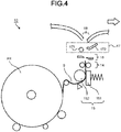
- Fig. 4 is a diagram illustrating the internal structure of the receipt printer 10.
- the receipt printer 10 detachably receives a rolled paper PR.
- the receipt printer 10 prints details on a paper S led from the rolled paper PR to discharge the paper S from the discharge port 18 as a receipt.
- the receipt printer 10 is provided with a controller 11, a communication interface 12, a storage section 13, a conveyance section 14, a printing section 15, a cut section 16 and a clamping section 17.
- the controller 11 is a processing device such as a processor.
- the controller 11 operates according to a program stored in a ROM (Read Only Memory) and a RAM (Random Access Memory) that are not shown, or the storage section 13, to realize various operations including a "receipt discharge processing" described later.
- the controller 11 functions as a discharge control module which controls the conveyance section 14, the cut section 16 and the clamping section 17 to discharge the paper from the discharge port 18.
- the communication interface 12 communicates with a control device (for example, processor) of the commodity information processing apparatus 1.
- the communication interface 12 acquires various data from the commodity information processing apparatus 1 to transmit it to the storage section 13.
- the data acquired by the communication interface 12 from the commodity information processing apparatus 1 contains information (for example, transaction details) to be printed on the receipt by the printing section 15.
- information printed by the printing section 15 on the receipt is referred to as a print data.
- the storage section 13 is a data readable and writable storage device such as a DRAM (Dynamic Random Access Memory), an SRAM (Static Random Access Memory), a flash memory, a hard disk and the like.
- the storage section 13 may be a built-in memory of the controller 11 or a memory separate from the controller 11.
- the storage section 13 stores information such as the transaction details received by the communication interface 12 and a program for operating the controller 11.
- the conveyance section 14 is a device (or a mechanism) for conveying the paper S led from the rolled paper PR towards the discharge port 18. As shown in Fig. 4 , the conveyance section 14 is a pair of rollers arranged to face each other across a movement route of the paper S. The constitution of the conveyance section 14 is not limited to that.
- the paper S may be conveyed by the rotation of a platen roller 152 of the printing section 15 to draw the paper S out of the rolled paper PR.
- the printing section 15 is used to print various information such as a transaction details on the paper S.
- the printing section 15 is a thermal print unit.
- the printing section 15 includes a thermal head 151 and the platen roller 152.
- the printing section 15 prints information such as a transaction details on the paper S under the control of the controller 11.
- the cut section 16 is a cutter, e.g., a slide type cutter, for cutting a part becoming the receipt from the paper S.
- the constitution of the cut section 16 is not limited to that, and various modifications are enabled.
- the cut section 16 enables both full cut and partial cut.
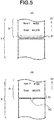
- Fig. 5(A) is a diagram illustrating a state in which the paper S is completely cut.
- Fig. 5(B) is a diagram illustrating a state in which the paper S is partially cut.
- a part (Er shown in Fig. 5(A) ), i.e., a rear end of a receipt Sr, is completely separated from the paper S.
- the part becoming the receipt is partially separated from the paper.
- the cut section completes the separation of the receipt in a state in which a part (NC shown in Fig. 5(B) , hereinafter, referred to as a non-cut section) of a rear end Er of the receipt Sr remains.
- the operator eventually tears the non-cut section NC to separate the receipt Sr from the paper S.
- the non-cut section NC is positioned at the center of the rear end Er of the receipt Sr; however, the position of the non-cut section NC is not limited to that.
- the non-cut section NC may be positioned at a left edge and a right edge of the rear end Er.
- the number of the non-cut sections NC is not limited to one, and a plurality of the non-cut sections NC may be formed.
- FIG. 6(A) and Fig. 6(B) are enlarged views of the vicinity of the clamping section 17 of the receipt printer 10.
- a direction of an outline arrow in Fig. 6 (A) and Fig. 6 (B) is the device front side and an opposite direction thereto is the device rear side.
- the clamping section 17 includes a fixed section 171 (first section) and a movable section 172 (second section).
- the fixed section 171 is a roller fixed on the receipt printer 10 in a rotatable manner.
- a rotation shaft of the fixed section 171 faces a direction (backward direction in the drawing) orthogonal to a movement route P of the paper S.
- a rotational resistance force is applied to the roller constituting the fixed section 171.
- a fixed force is required to rotate the fixed section 171.
- the fixed section 171 is positioned in the front of the discharge port 18.
- the fixed section 171 is arranged at a position entering the inside of the receipt printer 10 along the movement route P from the discharge port 18.
- a distance from the discharge port 18 to the fixed section 171 is, for example, 1 cm ⁇ 10 cm.
- the fixed section 171 is positioned at the device rear side of the movement route P.
- the movable section 172 a movable member, for clamping the paper S with the fixed section 171.
- the movable section 172 is arranged to face the fixed section 171 across the movement route P of the paper S.
- the movable section 172 is a plate-like member and an end thereof at the device rear side bends or curves obliquely upward.
- the movable section 172 is movable towards the device rear side.
- the movable section 172 includes a planar section 172a at obliquely lower side thereof.
- the movable section 172 passes the movement route P of the paper S and moves to the device rear side, and eventually the planar section 172a thereof abuts against the fixed section 171 via an elastic body (spring and the like) as shown in Fig.
- the planar section 172a abuts against the fixed section 171 side via the elastic body (not shown) ; however, the present embodiment is not limited to that.
- the planar section 172a may be moved in a direction shown in Fig. 6 (A) and then a movable mechanism may be arranged in the fixed section 171 to abut against the planar section 172a via the elastic body (not shown).
- a smaller angle r1 (i.e., inferior angle) of angles formed by the planar section 172a and a paper discharge direction D1 is greater than 90°.
- the paper discharge direction D1 is a direction in which the paper S is discharged from the discharge port 18.
- the controller 11 of the receipt printer 10 starts the receipt discharge processing if receiving a printing start command from the commodity information processing apparatus 1.
- data to be printed on the receipt i.e., print data
- the storage section 13 stores data to be printed on the receipt.
- the receipt discharge processing is described with reference to the flowchart in Fig. 7 .
- the controller 11 determines whether a length of the receipt is greater than a preset threshold value (ACT 101) . At this time, the controller 11 determines the length of the receipt on the basis of the print data stored in the storage section 13. For example, the controller 11 determines the length of the receipt according to the number of printing lines and a width of each line.
- ACT 102 If the length of the receipt is smaller than the preset threshold value (No in ACT 101), the controller 11 executes a discharge mode 1 (ACT 102). In the discharge mode 1, the paper S is discharged from the discharge port 18 without being clamped by the clamping section 17.
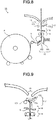
- Fig. 8 is a diagram illustrating a state in which the paper S is discharged in the discharge mode 1.
- the controller 11 controls the printing section 15 to print information on the paper S while controlling the conveyance section 14 to convey the paper S.
- the paper S passes between the fixed section 171 and the movable section 172 to be discharged from the discharge port 18.
- the controller 11 determines whether the printing is completed (ACT 103). If the printing is not completed (No in ACT 103), the controller 11 returns to the processing in ACT 102 to continue the printing operation and the discharge operation. If the printing is completed (Yes in ACT 103), the controller 11 controls the cut section 16 to separate the part which becomes the receipt from the paper S. At this time, the controller 11 carries out the partial cut so that a paper jam caused by the drop of the receipt to the inside of the receipt printer 10 does not occur. As shown in Fig. 5 (B) , the partial cut partially separates the part becoming the receipt from the paper S. If the receipt is short, even if the controller 11 executes the partial cut, there is rare possibility of dropping the receipt by being torn with its own weight.
- the controller 11 executes a discharge mode 2 (ACT 105).
- the discharge mode 2 the paper S is bent into the loop shape to be discharged from the discharge port 18.
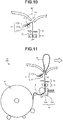
- Fig. 9 ⁇ Fig. 11 are diagrams illustrating a state in which the paper S is discharged in the discharge mode 2.
- the controller 11 prints information on the paper S while controlling the conveyance section 14 to convey the paper S.
- the controller 11 moves the movable section 172 towards the fixed section 171 as shown in Fig. 9 if the front end of the paper S is positioned in the front (i.e., the clamping section 17) of the discharge port 18. Then, the controller 11 clamps the front end of the paper S with the fixed section 171 and the movable section 172 as shown in Fig. 10 .
- the clamping section 17 clamps the front end of the paper S with a circumferential surface of the roller constituting the fixed section 171 and the planar section 172a of the movable section 172. If the controller 11 continues the conveyance of the paper S in this way, the paper S is bent into the loop shape and is discharged from the discharge port 18. Furthermore, the paper S is clamped by the fixed section 171 and the planar section 172a; however, at the time, a clamped part (front end) of the paper S is not necessarily stopped and may be in a clamped state in which the paper S moves slightly.
- Fig. 11 is a diagram illustrating a state in which the paper S is discharged from the discharge port 18 in a state of being bent into the loop shape.
- the planar section 172a is inclined towards the paper discharge direction D1.
- the paper clamping angle r1 at the time the clamping section 17 clamps the paper S is greater than 90°.
- the controller 11 controls the conveyance section 14 and the paper S is smoothly bent into the loop shape only by continuing the conveyance of the paper S after the front end of the paper S is clamped by the clamping section 17.
- the paper clamping angle r1 is formed by the paper discharge direction D1 and the planar section 172a as shown in Fig. 10 .
- the paper clamping angle r1 is an inferior angle and smaller than 180°.
- the printing section 15 is arranged to execute printing on an outer surface side of front and back surfaces of the paper S at the time the paper S is bent into the loop shape to be discharged from the discharge port 18.
- Fig. 12 is a diagram illustrating a state in which information is printed on an outer surface side of the receipt Sr.
- the device front side of the paper S located in the movement route P becomes the outer surface.
- the printing section 15 is arranged such that the thermal head 151 is located at the device front side of the movement route P as shown in Fig. 11 .
- the clamping section 17 is arranged to clamp the front end of the paper S at the device rear side of the movement route P of the paper S.
- the rear end Er of the receipt Sr is located at the device front side as shown in Fig. 12 .
- the controller 11 determines whether the printing is completed (ACT 106). If the printing is not completed (No in ACT 106), the controller 11 returns to the processing in ACT 105 to continue the printing operation and the discharge operation. If the printing is completed (Yes in ACT 106), the controller 11 controls the cut section 16 to separate the part becoming the receipt from the paper S. At this time, the controller 11 carries out the full cut so that the rear end of the receipt is neatly cut (ACT 107). The full cut completely separates the part becoming the receipt Sr from the paper S as shown in Fig. 5 (A) .
- the controller 11 terminates the receipt discharge processing.
- the receipt printer 10 bends the paper S into the loop shape to discharge it from the discharge port 18 by clamping the front end of the paper S in the front of the discharge port 18 in a case in which at least the length of the receipt is longer than a preset length. As the front end of the paper S is clamped, even if the receipt printer 10 completely cuts the paper S, the receipt Sr rarely falls out of the discharge port 18. Of course, even if the receipt printer 10 partially cuts the paper S, the receipt Sr rarely falls out of the discharge port 18.
- the operator hands over the receipt to a customer in a state of folding the receipt in half.
- the receipt printer 10 of the present embodiment bends the receipt into the loop shape to discharge it from the discharge port 18 if the receipt is long.
- the operator can easily fold the long receipt in half by sandwiching a middle part of the loop-like receipt from the front and back sides thereof and pulling it out from the discharge port 18.
- the operator may further fold the receipt in the folded state in half to fold the receipt in four. Because it does not take much time to fold the receipt in half or fold it in four, it is possible to realize improvement in a settlement processing by the operator.
- the receipt printer 10 If the length of the receipt is shorter than the preset length, and the clamping section 17 does not clamp the front end of the paper S, the receipt printer 10 partially cuts the sheet S, as in the past. Thus, the receipt rarely falls out of the discharge port 18. If the length of the receipt is shorter than the preset length as stated above, the receipt printer 10 straightly discharges the receipt Sr from the discharge port 18. Thus, the situation that the operator is hard to pick up the receipt because of the receipt, having a short length, which is bent into the loop shape does not occur. The operator may hand over the receipt in a natural shape, a straight line state, to the customer as it is.
- the receipt printer 10 In a case in which the receipt printer 10 carries out the partial cut, the operator must tear the non-cut section NC to take the receipt out of the discharge port 18. In this case, as a part of the non-cut section NC which is cut becomes coarse, the rear end Er of the receipt is not neat. However, the receipt printer 10 of the present embodiment completely cuts the paper S in a case in which the front end of the paper S is clamped by the clamping section 17. Thus, if at least the front end of the paper S is clamped by the clamping section 17, the rear end Er of the receipt is straight and neat.
- One of the sections (the fixed section in the present embodiment) constituting the clamping section 17 is a roller. Friction generated between the receipt and the clamping section 17 is small at the time the operator pulls out the receipt, and thus the receipt is rarely damaged even if the operator pulls out the receipt with a large force.
- the printing section 15 of the receipt printer 10 is arranged to carry out printing on the outer surface side of the front surface and the back surface of the paper S at the time the paper S is bent into the loop shape to be discharged from the discharge port 18.
- the operator can visually confirm information printed on the receipt in a state in which the receipt is located at the discharge port 18.
- the clamping section 17 of the receipt printer 10 is arranged such that the rear end Er of the receipt is located at the device front side at the time the paper S is bent into the loop shape to be discharged from the discharge port 18.
- a total amount (purchase amount), a deposited amount and a change amount are printed at the last part (rear end) of the receipt.
- the rear end Er of the receipt is located at the device front side, and in this way, the operator can confirm the total amount and the like printed on the receipt while the receipt is located at the discharge port 18.
- the fixed section 171 is a roller and the movable section 172 is a plate-like member having the planar section 172a.
- the constitution of the clamping section 17 is not limited to that.
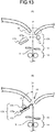
- Fig. 13 (A) shows a clamping section 17A as a modification of the clamping section 17 of the embodiment.
- the clamping section 17A is provided with a fixed section 173 (first section) and a movable section 174 (second section).
- the fixed section 173 is a plate-like member fixed in the receipt printer 10.
- the fixed section 173 is located at a position advancing towards the inner side of the receipt printer 10 along the movement route P of the paper S.
- a distance from the discharge port 18 to the fixed section 171 is, for example, 1cm ⁇ 10cm.
- the fixed section 173 is located at the device rear side of the movement route P.
- the fixed section 173 has a planar section 173a at an obliquely upper side.
- the movable section 174 is a movable member for clamping the paper S together with the fixed section 173.
- the movable section 174 is arranged to face the fixed section 173 across the movement route P of the paper S.
- a rotation shaft of the movable section 174 faces a direction (backward direction in Fig. 13(A) ) orthogonal to the movement route P of the paper S.
- a roller constituting the movable section 174 is applied with a rotation resistance force.
- a fixed force is required to rotate the movable section 174.
- the movable section 174 moves to the fixed section 173 side over the movement route P of the paper S under the control of the controller 11.
- Fig. 13(B) is a diagram illustrating a state in which the clamping section 17A clamps the front end of the paper S with the planar section 173a of the fixed section 173 and a circumferential surface of the movable section 174.
- the planar section 173a is inclined with respect to the paper discharge direction D1.
- a paper clamping angle r2 formed by the paper discharge direction D1 and the planar section 173a is greater than 90°.
- the movable section 174 (second section) is not limited to a roller.
- the movable section 174 may be a plate-like member having the planar section at a side facing the paper S at the time the front end of the paper S is clamped.
- the fixed section 173 (first section) may be a part of a housing of the receipt printer 10.
- the fixed section 171 (first section) included in the clamping section 17 is set to the roller as shown in Fig. 11 ; however, the fixed section 171 is not limited to the roller.
- the fixed section 171 may be a plate-like member having the planar section at a side facing the paper S at the time the front end of the paper S is clamped.
- the fixed section 171 may be a part of a housing of the receipt printer 10.
- any one of the first section and the second section constituting the clamping section 17 or the clamping section 17A is set to the roller; however, both of them may be rollers.
- the rotation resistance force may be applied to both rollers, or may be applied to only either of the two rollers. The friction generated between the receipt and the clamping section at the time the operator pulls out the receipt can be reduced.
- the receipt printer 10 completely cuts the paper S in a case in which the front end of the paper S is clamped by the clamping section 17.
- the receipt printer 10 may partially cut the paper S even if the front end of the paper S is clamped by the clamping section 17.
- the receipt printer 10 discharges the receipt Sr from the discharge port 18 in a straight shape while the front end of the paper S is not clamped by the clamping section 17 if the length of the receipt is smaller than the present threshold value.
- the receipt printer 10 may bend the paper S into the loop shape to discharge it from the discharge port 18 by clamping the front end of the paper S with the clamping section 17 even if the length of the receipt is smaller than the preset threshold value.
- the discharge port 18 is opened upward; however, the discharge port 18 may not necessarily be opened upward.
- the discharge port 18 may be opened in a horizontal direction.
- the printing section 15 is a thermal print unit; however, the printing section 15 is not limited to the thermal print unit.
- the printing section 15 may be an impact dot type, an ink jet type, or an electrophotographic print unit.
- the receipt printer 10 is fixed or built in the commodity information processing apparatus 1; however, the receipt printer 10 may be attached to the commodity information processing apparatus 1.
- the receipt printer 10 may have a connection interface such as a USB (Universal Serial Bus) or the like to be capable of being connected to the commodity information processing apparatus 1 by a communication cable such as a USB cable or the like.
- a connection interface such as a USB (Universal Serial Bus) or the like to be capable of being connected to the commodity information processing apparatus 1 by a communication cable such as a USB cable or the like.
- the receipt printer 10 may have a user interface and operate as a single unit independent of the commodity information processing apparatus 1.
- the receipt printer 10 may also be connected to a personal computer to operate according to an instruction of the personal computer.
- the receipt printer 10 is fixed or built in the commodity information processing apparatus 1.
- the commodity information processing apparatus 1 may directly issue the receipt without passing through the receipt printer 10.
- the commodity information processing apparatus 1 may include the controller (discharge control module) 11, the communication interface 12, the storage section 13, the conveyance section 14, the printing section 15, the cut section 16, the clamping section 17 and the discharge port 18.
- the controller 11 may be common to a control device (for example, a processor) for controlling each section of the commodity information processing apparatus 1.
- the commodity information processing apparatus 1 is the POS terminal; however, the commodity information processing apparatus 1 is not limited to the POS terminal.
- the commodity information processing apparatus 1 may be a stand-alone cash register which does not have a network connection function.
- the receipt printer 10 is installed in the POS terminal or the stand-alone cash register; however, the device in which the receipt printer 10 is installed may be other devices such as a vending machine.
- the control device for controlling the receipt printer 10 or the commodity information processing apparatus 1 may be realized by a dedicated computer system or by a general computer system.
- a program for executing the above-described operation may be stored in a computer-readable recording medium such as an optical disk, a semiconductor memory, a magnetic tape, a flexible disk and the like to be distributed, and the program may be installed in the computer to execute the above processing to constitute the control device.
- the control device may be a computer (processor) included in the receipt printer 10 or the commodity information processing apparatus 1, or may be a computer for controlling the receipt printer 10 or the commodity information processing apparatus 1 from the outside.
- the above program may be stored in a disk device included in a server device on a network such as the Internet to be capable of being downloaded to a computer or the like.
- the above-described function may be realized by cooperation of an OS (Operating System) and application software.
- OS Operating System
- application software In this case, a part other than the OS may be stored in the medium to be distributed, or may be stored in the server device to be capable of being downloaded to the computer.
Landscapes
- Physics & Mathematics (AREA)
- General Physics & Mathematics (AREA)
- Business, Economics & Management (AREA)
- Accounting & Taxation (AREA)
- General Business, Economics & Management (AREA)
- Strategic Management (AREA)
- Finance (AREA)
- Engineering & Computer Science (AREA)
- Theoretical Computer Science (AREA)
- Cash Registers Or Receiving Machines (AREA)
- Handling Of Sheets (AREA)
- Handling Of Continuous Sheets Of Paper (AREA)
- Advancing Webs (AREA)
Abstract
Description
- Embodiments described herein relate generally to a receipt printer.
- A commodity information processing apparatus (for example, POS terminal) is generally equipped with a receipt printer for printing information such as a transaction details on a receipt. The receipt printer prints information on a rolled paper and cuts the paper to discharge it from a discharge port. At this time, there is a case in which the receipt printer cuts the paper in a manner of a so-called partial cut so that the paper (receipt) does not drop or fall from the discharge port to an inner side (for example, a conveyance path of the paper) or an outer side (for example, floor) of the printer. In the partial cut, the paper is partially cut or separated from the rolled paper to leave a part thereof along the cutting direction when the paper becoming the receipt is separated from the rolled paper.
-
-
Fig. 1 is a perspective view illustrating a commodity information processing apparatus provided with a receipt printer according to an embodiment; -
Fig. 2 is a perspective view of the receipt printer according to the present embodiment; -
Fig. 3 is a block diagram of the receipt printer; -
Fig. 4 is a diagram illustrating the internal structure of the receipt printer; -
Fig. 5(A) is a diagram illustrating a state in which a paper is completely cut, andFig. 5(B) is a diagram illustrating a state in which a paper is partially cut; -
Fig. 6 (A) is a diagram illustrating a clamping section in a state in which a fixed section and a movable section are separated, andFig. 6 (B) is a diagram illustrating the clamping section in a state in which the fixed section and the movable section are close to each other; -
Fig. 7 is a flowchart illustrating a receipt discharge processing according to the present embodiment; -
Fig. 8 is a diagram illustrating a state in which the paper is directly discharged from a discharge port without clamping a front end of the paper by the clamping section; -
Fig. 9 is a diagram illustrating a state in which the movable section is moved towards the fixed section; -
Fig. 10 is a diagram illustrating a state in which the front end of the paper is clamped by the fixed section and the movable section; -
Fig. 11 is a diagram illustrating a state in which the paper is discharged from the discharge port in a state of being bent into a loop shape; -
Fig. 12 is a diagram illustrating a state in which information is printed on an outer surface of the receipt; and -
Fig. 13 (A) is a diagram illustrating a modification of the clamping section, andFig. 13(B) is a diagram illustrating a state in which the clamping section clamps a paper between a fixed section and a movable section. - In accordance with an embodiment, a receipt printer comprises a discharge port configured to discharge a receipt, a conveyance section configured to convey a paper becoming the receipt to the discharge port; a clamping section configured to clamp the paper at an upstream side of the discharge port in a conveyance direction of the paper; and a controller configured to control the clamping section and the conveyance section such that the paper is bent into a loop shape to be discharged from the discharge port by clamping a front end of the paper with the clamping section and conveying the paper towards the discharge port while the front end of the paper is clamped by the clamping section.
- Preferably, the clamping section includes a first section and a second section to clamp the front end of the paper with the first section and the second section.
- Preferably, at least one of the first section and the second section is provided with a planar section at a side thereof facing the paper.
- Preferably, the planar section is inclined towards a paper discharge direction in which the paper is discharged from the discharge port to form a paper clamping angle greater than 90° by the paper discharge direction and the planar section at the time the paper is clamped.
- Preferably, at least one of the first section and the second section is a roller.
- The clamping section may clamp the paper between a circumferential surface of the roller and the other section of the clamping section.
- The receipt printer may further comprise: a cut section configured to separate a part becoming the receipt from the paper, wherein the discharge control module carries out a full cut to completely separate the part becoming the receipt from the paper in a case in which at least the front end of the paper is clamped by the clamping section.
- The receipt printer may further comprise: a printing section configured to print information on the paper.
- Preferably, the printing section carries out printing on an outer surface side of front and back surfaces of the paper at the time the paper is bent into the loop shape to be discharged from the discharge port.
- Hereinafter, embodiments for realizing the invention are described with reference to the accompanying drawings. In the drawings, the same or equivalent components are donated with the same reference numerals.
-
Fig. 1 is a perspective view illustrating a commodityinformation processing apparatus 1 provided with areceipt printer 10 according to the embodiment. The commodityinformation processing apparatus 1 is, for example, a POS (Point Of Sales) terminal. The commodityinformation processing apparatus 1 is arranged at each store and is operated by an operator, e.g., store clerk. The commodityinformation processing apparatus 1 is connected to a store server, i.e., POS server, (not shown) via a network. Thereceipt printer 10 is fixed or built in the commodityinformation processing apparatus 1. -
Fig. 2 is a perspective view of thereceipt printer 10 taken out of the commodityinformation processing apparatus 1. Thereceipt printer 10 is used to issue a receipt. Thereceipt printer 10 is provided with adischarge port 18 for discharging the receipt. Thedischarge port 18 is opened upward. The appearances of theport 18 shown inFig. 1 and Fig. 2 are merely examples, and various modifications are enabled. In the following description, a front side (for example, a side where an operator stands at) of thereceipt printer 10 is referred to as a "device front side", and an opposite side thereof is referred to as a "device rear side". In the example inFig. 2 , the device front side is a direction shown by an outline arrow, and the device rear side is an opposite direction thereto. -
Fig. 3 is a block diagram of thereceipt printer 10.Fig. 4 is a diagram illustrating the internal structure of thereceipt printer 10. Thereceipt printer 10 detachably receives a rolled paper PR. Thereceipt printer 10 prints details on a paper S led from the rolled paper PR to discharge the paper S from thedischarge port 18 as a receipt. - As shown in
Fig. 3 , thereceipt printer 10 is provided with acontroller 11, acommunication interface 12, astorage section 13, aconveyance section 14, aprinting section 15, acut section 16 and aclamping section 17. - The
controller 11 is a processing device such as a processor. Thecontroller 11 operates according to a program stored in a ROM (Read Only Memory) and a RAM (Random Access Memory) that are not shown, or thestorage section 13, to realize various operations including a "receipt discharge processing" described later. Thecontroller 11 functions as a discharge control module which controls theconveyance section 14, thecut section 16 and theclamping section 17 to discharge the paper from thedischarge port 18. - The
communication interface 12 communicates with a control device (for example, processor) of the commodityinformation processing apparatus 1. Thecommunication interface 12 acquires various data from the commodityinformation processing apparatus 1 to transmit it to thestorage section 13. The data acquired by thecommunication interface 12 from the commodityinformation processing apparatus 1 contains information (for example, transaction details) to be printed on the receipt by theprinting section 15. In the following description, information printed by theprinting section 15 on the receipt is referred to as a print data. - The
storage section 13 is a data readable and writable storage device such as a DRAM (Dynamic Random Access Memory), an SRAM (Static Random Access Memory), a flash memory, a hard disk and the like. Thestorage section 13 may be a built-in memory of thecontroller 11 or a memory separate from thecontroller 11. Thestorage section 13 stores information such as the transaction details received by thecommunication interface 12 and a program for operating thecontroller 11. - The
conveyance section 14 is a device (or a mechanism) for conveying the paper S led from the rolled paper PR towards thedischarge port 18. As shown inFig. 4 , theconveyance section 14 is a pair of rollers arranged to face each other across a movement route of the paper S. The constitution of theconveyance section 14 is not limited to that. For example, the paper S may be conveyed by the rotation of aplaten roller 152 of theprinting section 15 to draw the paper S out of the rolled paper PR. - The
printing section 15 is used to print various information such as a transaction details on the paper S. Theprinting section 15 is a thermal print unit. Theprinting section 15 includes athermal head 151 and theplaten roller 152. Theprinting section 15 prints information such as a transaction details on the paper S under the control of thecontroller 11. - The
cut section 16 is a cutter, e.g., a slide type cutter, for cutting a part becoming the receipt from the paper S. Of course, the constitution of thecut section 16 is not limited to that, and various modifications are enabled. Thecut section 16 enables both full cut and partial cut.Fig. 5(A) is a diagram illustrating a state in which the paper S is completely cut.Fig. 5(B) is a diagram illustrating a state in which the paper S is partially cut. - In the full cut, the part becoming the receipt is completely separated from the paper. For example, as shown in
Fig. 5(A) , a part (Er shown inFig. 5(A) ), i.e., a rear end of a receipt Sr, is completely separated from the paper S. - In the partial cut, the part becoming the receipt is partially separated from the paper. For example, as shown in
Fig. 5(B) , in the partial cut, the cut section completes the separation of the receipt in a state in which a part (NC shown inFig. 5(B) , hereinafter, referred to as a non-cut section) of a rear end Er of the receipt Sr remains. In this case, the operator eventually tears the non-cut section NC to separate the receipt Sr from the paper S. Further, inFig. 5(B) , the non-cut section NC is positioned at the center of the rear end Er of the receipt Sr; however, the position of the non-cut section NC is not limited to that. For example, the non-cut section NC may be positioned at a left edge and a right edge of the rear end Er. The number of the non-cut sections NC is not limited to one, and a plurality of the non-cut sections NC may be formed. - Returning to
Fig. 4 , theclamping section 17 clamps the paper S in the front of the discharge port 18 (upstream side in a conveyance direction of the paper S).Fig. 6(A) and Fig. 6(B) are enlarged views of the vicinity of theclamping section 17 of thereceipt printer 10. A direction of an outline arrow inFig. 6 (A) and Fig. 6 (B) is the device front side and an opposite direction thereto is the device rear side. Theclamping section 17 includes a fixed section 171 (first section) and a movable section 172 (second section). - The fixed
section 171 is a roller fixed on thereceipt printer 10 in a rotatable manner. A rotation shaft of the fixedsection 171 faces a direction (backward direction in the drawing) orthogonal to a movement route P of the paper S. A rotational resistance force is applied to the roller constituting the fixedsection 171. Thus, a fixed force is required to rotate the fixedsection 171. The fixedsection 171 is positioned in the front of thedischarge port 18. InFig. 6 (A) , the fixedsection 171 is arranged at a position entering the inside of thereceipt printer 10 along the movement route P from thedischarge port 18. A distance from thedischarge port 18 to the fixedsection 171 is, for example, 1 cm∼10 cm. The fixedsection 171 is positioned at the device rear side of the movement route P. - The
movable section 172, a movable member, for clamping the paper S with the fixedsection 171. Themovable section 172 is arranged to face the fixedsection 171 across the movement route P of the paper S. Themovable section 172 is a plate-like member and an end thereof at the device rear side bends or curves obliquely upward. Themovable section 172 is movable towards the device rear side. Themovable section 172 includes aplanar section 172a at obliquely lower side thereof. Themovable section 172 passes the movement route P of the paper S and moves to the device rear side, and eventually theplanar section 172a thereof abuts against the fixedsection 171 via an elastic body (spring and the like) as shown inFig. 6(B) . In the present embodiment, theplanar section 172a abuts against the fixedsection 171 side via the elastic body (not shown) ; however, the present embodiment is not limited to that. For example, theplanar section 172a may be moved in a direction shown inFig. 6 (A) and then a movable mechanism may be arranged in the fixedsection 171 to abut against theplanar section 172a via the elastic body (not shown). A smaller angle r1 (i.e., inferior angle) of angles formed by theplanar section 172a and a paper discharge direction D1 is greater than 90°. The paper discharge direction D1 is a direction in which the paper S is discharged from thedischarge port 18. - An operation of the
receipt printer 10 having such an above constitution is described. - The
controller 11 of thereceipt printer 10 starts the receipt discharge processing if receiving a printing start command from the commodityinformation processing apparatus 1. As stated above, data to be printed on the receipt, i.e., print data, is stored in thestorage section 13. Hereinafter, the receipt discharge processing is described with reference to the flowchart inFig. 7 . - The
controller 11 determines whether a length of the receipt is greater than a preset threshold value (ACT 101) . At this time, thecontroller 11 determines the length of the receipt on the basis of the print data stored in thestorage section 13. For example, thecontroller 11 determines the length of the receipt according to the number of printing lines and a width of each line. - If the length of the receipt is smaller than the preset threshold value (No in ACT 101), the
controller 11 executes a discharge mode 1 (ACT 102). In thedischarge mode 1, the paper S is discharged from thedischarge port 18 without being clamped by theclamping section 17.Fig. 8 is a diagram illustrating a state in which the paper S is discharged in thedischarge mode 1. Thecontroller 11 controls theprinting section 15 to print information on the paper S while controlling theconveyance section 14 to convey the paper S. The paper S passes between thefixed section 171 and themovable section 172 to be discharged from thedischarge port 18. - The
controller 11 determines whether the printing is completed (ACT 103). If the printing is not completed (No in ACT 103), thecontroller 11 returns to the processing in ACT 102 to continue the printing operation and the discharge operation. If the printing is completed (Yes in ACT 103), thecontroller 11 controls thecut section 16 to separate the part which becomes the receipt from the paper S. At this time, thecontroller 11 carries out the partial cut so that a paper jam caused by the drop of the receipt to the inside of thereceipt printer 10 does not occur. As shown inFig. 5 (B) , the partial cut partially separates the part becoming the receipt from the paper S. If the receipt is short, even if thecontroller 11 executes the partial cut, there is rare possibility of dropping the receipt by being torn with its own weight. - Returning to ACT 101 in
Fig. 7 , if the length of the receipt is greater than the preset threshold value (Yes in ACT 101), thecontroller 11 executes a discharge mode 2 (ACT 105). In thedischarge mode 2, the paper S is bent into the loop shape to be discharged from thedischarge port 18. -
Fig. 9∼Fig. 11 are diagrams illustrating a state in which the paper S is discharged in thedischarge mode 2. Thecontroller 11 prints information on the paper S while controlling theconveyance section 14 to convey the paper S. Thecontroller 11 moves themovable section 172 towards the fixedsection 171 as shown inFig. 9 if the front end of the paper S is positioned in the front (i.e., the clamping section 17) of thedischarge port 18. Then, thecontroller 11 clamps the front end of the paper S with the fixedsection 171 and themovable section 172 as shown inFig. 10 . Theclamping section 17 clamps the front end of the paper S with a circumferential surface of the roller constituting the fixedsection 171 and theplanar section 172a of themovable section 172. If thecontroller 11 continues the conveyance of the paper S in this way, the paper S is bent into the loop shape and is discharged from thedischarge port 18. Furthermore, the paper S is clamped by the fixedsection 171 and theplanar section 172a; however, at the time, a clamped part (front end) of the paper S is not necessarily stopped and may be in a clamped state in which the paper S moves slightly. Even in that case, compared with a movement speed of the front end of the paper S, as a conveyance speed of theconveyance section 14 is high, the paper S is bent into the loop shape with such speed difference. Thecontroller 11 sets the speed of print of information on the paper S and the speed of the conveyance of the paper S at a higher rate compared with thedischarge mode 1, and may discharge the paper S at the higher speed compared with thedischarge mode 1.Fig. 11 is a diagram illustrating a state in which the paper S is discharged from thedischarge port 18 in a state of being bent into the loop shape. - Furthermore, the
planar section 172a is inclined towards the paper discharge direction D1. The paper clamping angle r1 at the time theclamping section 17 clamps the paper S is greater than 90°. Thus, thecontroller 11 controls theconveyance section 14 and the paper S is smoothly bent into the loop shape only by continuing the conveyance of the paper S after the front end of the paper S is clamped by theclamping section 17. The paper clamping angle r1 is formed by the paper discharge direction D1 and theplanar section 172a as shown inFig. 10 . The paper clamping angle r1 is an inferior angle and smaller than 180°. - The
printing section 15 is arranged to execute printing on an outer surface side of front and back surfaces of the paper S at the time the paper S is bent into the loop shape to be discharged from thedischarge port 18.Fig. 12 is a diagram illustrating a state in which information is printed on an outer surface side of the receipt Sr. In the case of thereceipt printer 10 of the present embodiment, the device front side of the paper S located in the movement route P becomes the outer surface. Thus, theprinting section 15 is arranged such that thethermal head 151 is located at the device front side of the movement route P as shown inFig. 11 . - The
clamping section 17 is arranged to clamp the front end of the paper S at the device rear side of the movement route P of the paper S. Thus, at the time the paper S is bent into the loop shape to be discharged from thedischarge port 18, the rear end Er of the receipt Sr is located at the device front side as shown inFig. 12 . - Returning to
Fig. 7 , thecontroller 11 determines whether the printing is completed (ACT 106). If the printing is not completed (No in ACT 106), thecontroller 11 returns to the processing in ACT 105 to continue the printing operation and the discharge operation. If the printing is completed (Yes in ACT 106), thecontroller 11 controls thecut section 16 to separate the part becoming the receipt from the paper S. At this time, thecontroller 11 carries out the full cut so that the rear end of the receipt is neatly cut (ACT 107). The full cut completely separates the part becoming the receipt Sr from the paper S as shown inFig. 5 (A) . - After the separation of the part becoming the receipt, the
controller 11 terminates the receipt discharge processing. - In accordance with the present embodiment, the
receipt printer 10 bends the paper S into the loop shape to discharge it from thedischarge port 18 by clamping the front end of the paper S in the front of thedischarge port 18 in a case in which at least the length of the receipt is longer than a preset length. As the front end of the paper S is clamped, even if thereceipt printer 10 completely cuts the paper S, the receipt Sr rarely falls out of thedischarge port 18. Of course, even if thereceipt printer 10 partially cuts the paper S, the receipt Sr rarely falls out of thedischarge port 18. - Generally, if the receipt is longer compared with the preset length, the operator hands over the receipt to a customer in a state of folding the receipt in half. The
receipt printer 10 of the present embodiment bends the receipt into the loop shape to discharge it from thedischarge port 18 if the receipt is long. Thus, the operator can easily fold the long receipt in half by sandwiching a middle part of the loop-like receipt from the front and back sides thereof and pulling it out from thedischarge port 18. At this time, the operator may further fold the receipt in the folded state in half to fold the receipt in four. Because it does not take much time to fold the receipt in half or fold it in four, it is possible to realize improvement in a settlement processing by the operator. - If the length of the receipt is shorter than the preset length, and the
clamping section 17 does not clamp the front end of the paper S, thereceipt printer 10 partially cuts the sheet S, as in the past. Thus, the receipt rarely falls out of thedischarge port 18. If the length of the receipt is shorter than the preset length as stated above, thereceipt printer 10 straightly discharges the receipt Sr from thedischarge port 18. Thus, the situation that the operator is hard to pick up the receipt because of the receipt, having a short length, which is bent into the loop shape does not occur. The operator may hand over the receipt in a natural shape, a straight line state, to the customer as it is. - In a case in which the
receipt printer 10 carries out the partial cut, the operator must tear the non-cut section NC to take the receipt out of thedischarge port 18. In this case, as a part of the non-cut section NC which is cut becomes coarse, the rear end Er of the receipt is not neat. However, thereceipt printer 10 of the present embodiment completely cuts the paper S in a case in which the front end of the paper S is clamped by theclamping section 17. Thus, if at least the front end of the paper S is clamped by theclamping section 17, the rear end Er of the receipt is straight and neat. - One of the sections (the fixed section in the present embodiment) constituting the
clamping section 17 is a roller. Friction generated between the receipt and theclamping section 17 is small at the time the operator pulls out the receipt, and thus the receipt is rarely damaged even if the operator pulls out the receipt with a large force. - The
printing section 15 of thereceipt printer 10 is arranged to carry out printing on the outer surface side of the front surface and the back surface of the paper S at the time the paper S is bent into the loop shape to be discharged from thedischarge port 18. Thus, the operator can visually confirm information printed on the receipt in a state in which the receipt is located at thedischarge port 18. - The
clamping section 17 of thereceipt printer 10 is arranged such that the rear end Er of the receipt is located at the device front side at the time the paper S is bent into the loop shape to be discharged from thedischarge port 18. In many cases, a total amount (purchase amount), a deposited amount and a change amount are printed at the last part (rear end) of the receipt. Thus, the rear end Er of the receipt is located at the device front side, and in this way, the operator can confirm the total amount and the like printed on the receipt while the receipt is located at thedischarge port 18. - The above embodiment is described merely as an example, and various modifications and applications are applicable.
- For example, in the
clamping section 17 of the above embodiment, the fixedsection 171 is a roller and themovable section 172 is a plate-like member having theplanar section 172a. However, the constitution of theclamping section 17 is not limited to that.Fig. 13 (A) shows aclamping section 17A as a modification of theclamping section 17 of the embodiment. Theclamping section 17A is provided with a fixed section 173 (first section) and a movable section 174 (second section). - The fixed
section 173 is a plate-like member fixed in thereceipt printer 10. The fixedsection 173 is located at a position advancing towards the inner side of thereceipt printer 10 along the movement route P of the paper S. - A distance from the
discharge port 18 to the fixedsection 171 is, for example, 1cm∼10cm. The fixedsection 173 is located at the device rear side of the movement route P. The fixedsection 173 has aplanar section 173a at an obliquely upper side. - The
movable section 174 is a movable member for clamping the paper S together with the fixedsection 173. Themovable section 174 is arranged to face the fixedsection 173 across the movement route P of the paper S. A rotation shaft of themovable section 174 faces a direction (backward direction inFig. 13(A) ) orthogonal to the movement route P of the paper S. A roller constituting themovable section 174 is applied with a rotation resistance force. Thus, a fixed force is required to rotate themovable section 174. Themovable section 174 moves to the fixedsection 173 side over the movement route P of the paper S under the control of thecontroller 11. -
Fig. 13(B) is a diagram illustrating a state in which theclamping section 17A clamps the front end of the paper S with theplanar section 173a of the fixedsection 173 and a circumferential surface of themovable section 174. Theplanar section 173a is inclined with respect to the paper discharge direction D1. At the time theclamping section 17 clamps the paper S, a paper clamping angle r2 formed by the paper discharge direction D1 and theplanar section 173a is greater than 90°. Thus, the paper S is smoothly bent into the loop shape by only continuing the conveyance of the paper S after the front end of the paper S is clamped by theclamping section 17. - Furthermore, the movable section 174 (second section) is not limited to a roller. The
movable section 174 may be a plate-like member having the planar section at a side facing the paper S at the time the front end of the paper S is clamped. The fixed section 173 (first section) may be a part of a housing of thereceipt printer 10. - In the above embodiment, the fixed section 171 (first section) included in the
clamping section 17 is set to the roller as shown inFig. 11 ; however, the fixedsection 171 is not limited to the roller. The fixedsection 171 may be a plate-like member having the planar section at a side facing the paper S at the time the front end of the paper S is clamped. The fixedsection 171 may be a part of a housing of thereceipt printer 10. - In the above embodiment, any one of the first section and the second section constituting the
clamping section 17 or theclamping section 17A is set to the roller; however, both of them may be rollers. The rotation resistance force may be applied to both rollers, or may be applied to only either of the two rollers. The friction generated between the receipt and the clamping section at the time the operator pulls out the receipt can be reduced. - In the above embodiment also, the
receipt printer 10 completely cuts the paper S in a case in which the front end of the paper S is clamped by theclamping section 17. However, thereceipt printer 10 may partially cut the paper S even if the front end of the paper S is clamped by theclamping section 17. - In the above embodiment, the
receipt printer 10 discharges the receipt Sr from thedischarge port 18 in a straight shape while the front end of the paper S is not clamped by theclamping section 17 if the length of the receipt is smaller than the present threshold value. However, thereceipt printer 10 may bend the paper S into the loop shape to discharge it from thedischarge port 18 by clamping the front end of the paper S with theclamping section 17 even if the length of the receipt is smaller than the preset threshold value. - In the above embodiment, the
discharge port 18 is opened upward; however, thedischarge port 18 may not necessarily be opened upward. For example, thedischarge port 18 may be opened in a horizontal direction. - In the above embodiment, the
printing section 15 is a thermal print unit; however, theprinting section 15 is not limited to the thermal print unit. For example, theprinting section 15 may be an impact dot type, an ink jet type, or an electrophotographic print unit. - In the above embodiment, the
receipt printer 10 is fixed or built in the commodityinformation processing apparatus 1; however, thereceipt printer 10 may be attached to the commodityinformation processing apparatus 1. For example, thereceipt printer 10 may have a connection interface such as a USB (Universal Serial Bus) or the like to be capable of being connected to the commodityinformation processing apparatus 1 by a communication cable such as a USB cable or the like. - The
receipt printer 10 may have a user interface and operate as a single unit independent of the commodityinformation processing apparatus 1. Thereceipt printer 10 may also be connected to a personal computer to operate according to an instruction of the personal computer. In the above embodiment, thereceipt printer 10 is fixed or built in the commodityinformation processing apparatus 1. However, the commodityinformation processing apparatus 1 may directly issue the receipt without passing through thereceipt printer 10. For example, the commodityinformation processing apparatus 1 may include the controller (discharge control module) 11, thecommunication interface 12, thestorage section 13, theconveyance section 14, theprinting section 15, thecut section 16, theclamping section 17 and thedischarge port 18. Thecontroller 11 may be common to a control device (for example, a processor) for controlling each section of the commodityinformation processing apparatus 1. - In the above embodiment, the commodity
information processing apparatus 1 is the POS terminal; however, the commodityinformation processing apparatus 1 is not limited to the POS terminal. For example, the commodityinformation processing apparatus 1 may be a stand-alone cash register which does not have a network connection function. - In the above embodiment, the
receipt printer 10 is installed in the POS terminal or the stand-alone cash register; however, the device in which thereceipt printer 10 is installed may be other devices such as a vending machine. - The control device for controlling the
receipt printer 10 or the commodityinformation processing apparatus 1 according to the present embodiment may be realized by a dedicated computer system or by a general computer system. For example, a program for executing the above-described operation may be stored in a computer-readable recording medium such as an optical disk, a semiconductor memory, a magnetic tape, a flexible disk and the like to be distributed, and the program may be installed in the computer to execute the above processing to constitute the control device. At this time, the control device may be a computer (processor) included in thereceipt printer 10 or the commodityinformation processing apparatus 1, or may be a computer for controlling thereceipt printer 10 or the commodityinformation processing apparatus 1 from the outside. Further, the above program may be stored in a disk device included in a server device on a network such as the Internet to be capable of being downloaded to a computer or the like. Further, the above-described function may be realized by cooperation of an OS (Operating System) and application software. In this case, a part other than the OS may be stored in the medium to be distributed, or may be stored in the server device to be capable of being downloaded to the computer. - While certain embodiments have been described, these embodiments have been presented by way of example only, and are not intended to limit the scope of the invention. Indeed, the novel embodiments described herein may be embodied in a variety of other forms; furthermore, various omissions, substitutions and changes in the form of the embodiments described herein may be made without departing from the framework of the invention. The accompanying claims and their equivalents are intended to cover such forms or modifications as would fall within the scope of the invention.
Claims (5)
- A receipt printer, comprising:a discharge port configured to discharge a receipt;a conveyance section configured to convey a paper becoming the receipt to the discharge port;a clamping section configured to clamp the paper at an upstream side of the discharge port in a conveyance direction of the paper; anda discharge control module configured to control the clamping section and the conveyance section such that the paper is bent into a loop shape and discharged from the discharge port by clamping a front end of the paper with the clamping section and conveying the paper towards the discharge port while the front end of the paper is clamped by the clamping section.
- The receipt printer according to claim 1, wherein the clamping section includes a first section and a second section to clamp the front end of the paper with the first section and the second section, wherein
at least one of the first section and the second section is provided with a planar section at a side thereof facing the paper, and the planar section is inclined towards a paper discharge direction in which the paper is discharged from the discharge port to form a paper clamping angle greater than 90 ° by the paper discharge direction and the planar section at the time the paper is clamped. - The receipt printer according to claim 2, wherein at least one of the first section and the second section is a roller, and the clamping section clamps the paper between a circumferential surface of the roller and the other section of the clamping section.
- The receipt printer according to any one of claims 1 to 3, further comprising:a cut section configured to separate a part becoming the receipt from the paper, wherein the discharge control module carries out a full cut to completely separate the part becoming the receipt from the paper in a case in which at least the front end of the paper is clamped by the clamping section.
- The receipt printer according to any one of claims 1 to 4, further comprising:a printing section configured to print information on the paper, whereinthe printing section carries out printing on an outer surface side of front and back surfaces of the paper at the time the paper is bent into the loop shape to be discharged from the discharge port.
Applications Claiming Priority (1)
| Application Number | Priority Date | Filing Date | Title |
|---|---|---|---|
| JP2016101683A JP6754611B2 (en) | 2016-05-20 | 2016-05-20 | Receipt printer |
Publications (2)
| Publication Number | Publication Date |
|---|---|
| EP3257678A1 true EP3257678A1 (en) | 2017-12-20 |
| EP3257678B1 EP3257678B1 (en) | 2019-12-04 |
Family
ID=58738927
Family Applications (1)
| Application Number | Title | Priority Date | Filing Date |
|---|---|---|---|
| EP17171862.0A Active EP3257678B1 (en) | 2016-05-20 | 2017-05-19 | Receipt printer |
Country Status (4)
| Country | Link |
|---|---|
| US (2) | US20170337785A1 (en) |
| EP (1) | EP3257678B1 (en) |
| JP (1) | JP6754611B2 (en) |
| CN (1) | CN107424363B (en) |
Families Citing this family (1)
| Publication number | Priority date | Publication date | Assignee | Title |
|---|---|---|---|---|
| CN109255901A (en) * | 2018-08-29 | 2019-01-22 | 浙江建林电子电气股份有限公司 | Billing machine |
Citations (4)
| Publication number | Priority date | Publication date | Assignee | Title |
|---|---|---|---|---|
| US6428226B1 (en) * | 1997-08-21 | 2002-08-06 | Star Micronics Co., Ltd. | Paper discharge apparatus |
| WO2006046454A1 (en) * | 2004-10-26 | 2006-05-04 | Star Micronics Co., Ltd. | Label printer |
| US20130014624A1 (en) * | 2011-07-11 | 2013-01-17 | Toshiba Tec Kabushiki Kaisha | Paper discharging apparatus, paper discharging method, image forming apparatus and image forming method |
| US20140253660A1 (en) * | 2013-03-05 | 2014-09-11 | Toshiba Tec Kabushiki Kaisha | Printing apparatus |
Family Cites Families (5)
| Publication number | Priority date | Publication date | Assignee | Title |
|---|---|---|---|---|
| EP1314569A3 (en) * | 1997-01-13 | 2004-06-23 | Canon Finetech Inc. | Roll paper unit and image formation apparatus |
| EP1013456B1 (en) * | 1997-01-31 | 2006-03-15 | Canon Finetech Inc. | Image forming device |
| JP2010042630A (en) * | 2008-08-18 | 2010-02-25 | Seiko Epson Corp | Printer, control method of printer, and printing system |
| JP5133375B2 (en) * | 2010-07-12 | 2013-01-30 | 東芝テック株式会社 | Paper discharge device, paper discharge method, image forming apparatus, and image forming method |
| CN102848740B (en) * | 2011-06-30 | 2015-01-28 | 山东新北洋信息技术股份有限公司 | Paper holding mechanism and printing device with same |
-
2016
- 2016-05-20 JP JP2016101683A patent/JP6754611B2/en active Active
-
2017
- 2017-05-19 CN CN201710358750.XA patent/CN107424363B/en active Active
- 2017-05-19 EP EP17171862.0A patent/EP3257678B1/en active Active
- 2017-05-19 US US15/599,699 patent/US20170337785A1/en not_active Abandoned
-
2019
- 2019-11-20 US US16/689,140 patent/US20200090472A1/en not_active Abandoned
Patent Citations (4)
| Publication number | Priority date | Publication date | Assignee | Title |
|---|---|---|---|---|
| US6428226B1 (en) * | 1997-08-21 | 2002-08-06 | Star Micronics Co., Ltd. | Paper discharge apparatus |
| WO2006046454A1 (en) * | 2004-10-26 | 2006-05-04 | Star Micronics Co., Ltd. | Label printer |
| US20130014624A1 (en) * | 2011-07-11 | 2013-01-17 | Toshiba Tec Kabushiki Kaisha | Paper discharging apparatus, paper discharging method, image forming apparatus and image forming method |
| US20140253660A1 (en) * | 2013-03-05 | 2014-09-11 | Toshiba Tec Kabushiki Kaisha | Printing apparatus |
Also Published As
| Publication number | Publication date |
|---|---|
| US20170337785A1 (en) | 2017-11-23 |
| CN107424363A (en) | 2017-12-01 |
| JP6754611B2 (en) | 2020-09-16 |
| CN107424363B (en) | 2020-01-31 |
| US20200090472A1 (en) | 2020-03-19 |
| JP2017205986A (en) | 2017-11-24 |
| EP3257678B1 (en) | 2019-12-04 |
Similar Documents
| Publication | Publication Date | Title |
|---|---|---|
| JP2007038557A (en) | Method of controlling printer, printer and program | |
| EP3257678B1 (en) | Receipt printer | |
| JP5785971B2 (en) | Printer device | |
| EP3257679B1 (en) | Receipt printer | |
| JP5974499B2 (en) | RECORDING DEVICE, CONTROL DEVICE, AND RECORDING DEVICE CONTROL METHOD | |
| US11110698B2 (en) | Sheet gripping mechanism and printer | |
| JP2017217816A (en) | Printer | |
| EP3076652B1 (en) | Hybrid media processing device capable of guiding bendable media such as cheques and non-bendable media such as id cards and driving licences | |
| JP7058695B2 (en) | Receipt printer | |
| JP2001310848A (en) | Printer | |
| US9180685B1 (en) | Printer apparatus | |
| JP5622810B2 (en) | Printer device | |
| JP6146080B2 (en) | Recording device | |
| JP6979776B2 (en) | Receipt printer | |
| CN208593167U (en) | Bill printer | |
| US11834290B2 (en) | Printing apparatus | |
| CN110936733B (en) | Printer, control method, computer-readable storage medium, and electronic device | |
| JP2018090393A (en) | Medium processing device | |
| JP6623601B2 (en) | Printing device and medium storage unit | |
| JP6217341B2 (en) | Printing device and medium issuing device | |
| JP2012196863A (en) | Image recorder, and method of controlling image recorder | |
| JP2005067124A (en) | Printer and commodity sales data processor | |
| JP2014024637A (en) | Paper jam detection device and image forming apparatus using the same | |
| JP2004009394A (en) | Receipt printer |
Legal Events
| Date | Code | Title | Description |
|---|---|---|---|
| PUAI | Public reference made under article 153(3) epc to a published international application that has entered the european phase |
Free format text: ORIGINAL CODE: 0009012 |
|
| STAA | Information on the status of an ep patent application or granted ep patent |
Free format text: STATUS: THE APPLICATION HAS BEEN PUBLISHED |
|
| AK | Designated contracting states |
Kind code of ref document: A1 Designated state(s): AL AT BE BG CH CY CZ DE DK EE ES FI FR GB GR HR HU IE IS IT LI LT LU LV MC MK MT NL NO PL PT RO RS SE SI SK SM TR |
|
| AX | Request for extension of the european patent |
Extension state: BA ME |
|
| STAA | Information on the status of an ep patent application or granted ep patent |
Free format text: STATUS: REQUEST FOR EXAMINATION WAS MADE |
|
| 17P | Request for examination filed |
Effective date: 20180620 |
|
| RBV | Designated contracting states (corrected) |
Designated state(s): AL AT BE BG CH CY CZ DE DK EE ES FI FR GB GR HR HU IE IS IT LI LT LU LV MC MK MT NL NO PL PT RO RS SE SI SK SM TR |
|
| GRAP | Despatch of communication of intention to grant a patent |
Free format text: ORIGINAL CODE: EPIDOSNIGR1 |
|
| STAA | Information on the status of an ep patent application or granted ep patent |
Free format text: STATUS: GRANT OF PATENT IS INTENDED |
|
| INTG | Intention to grant announced |
Effective date: 20190828 |
|
| GRAS | Grant fee paid |
Free format text: ORIGINAL CODE: EPIDOSNIGR3 |
|
| GRAA | (expected) grant |
Free format text: ORIGINAL CODE: 0009210 |
|
| STAA | Information on the status of an ep patent application or granted ep patent |
Free format text: STATUS: THE PATENT HAS BEEN GRANTED |
|
| RAP1 | Party data changed (applicant data changed or rights of an application transferred) |
Owner name: TOSHIBA TEC KABUSHIKI KAISHA |
|
| AK | Designated contracting states |
Kind code of ref document: B1 Designated state(s): AL AT BE BG CH CY CZ DE DK EE ES FI FR GB GR HR HU IE IS IT LI LT LU LV MC MK MT NL NO PL PT RO RS SE SI SK SM TR |
|
| REG | Reference to a national code |
Ref country code: GB Ref legal event code: FG4D |
|
| REG | Reference to a national code |
Ref country code: CH Ref legal event code: EP |
|
| REG | Reference to a national code |
Ref country code: AT Ref legal event code: REF Ref document number: 1208904 Country of ref document: AT Kind code of ref document: T Effective date: 20191215 |
|
| REG | Reference to a national code |
Ref country code: DE Ref legal event code: R096 Ref document number: 602017009249 Country of ref document: DE |
|
| REG | Reference to a national code |
Ref country code: IE Ref legal event code: FG4D |
|
| REG | Reference to a national code |
Ref country code: NL Ref legal event code: MP Effective date: 20191204 |
|
| REG | Reference to a national code |
Ref country code: LT Ref legal event code: MG4D |
|
| PG25 | Lapsed in a contracting state [announced via postgrant information from national office to epo] |
Ref country code: LT Free format text: LAPSE BECAUSE OF FAILURE TO SUBMIT A TRANSLATION OF THE DESCRIPTION OR TO PAY THE FEE WITHIN THE PRESCRIBED TIME-LIMIT Effective date: 20191204 Ref country code: GR Free format text: LAPSE BECAUSE OF FAILURE TO SUBMIT A TRANSLATION OF THE DESCRIPTION OR TO PAY THE FEE WITHIN THE PRESCRIBED TIME-LIMIT Effective date: 20200305 Ref country code: NO Free format text: LAPSE BECAUSE OF FAILURE TO SUBMIT A TRANSLATION OF THE DESCRIPTION OR TO PAY THE FEE WITHIN THE PRESCRIBED TIME-LIMIT Effective date: 20200304 Ref country code: LV Free format text: LAPSE BECAUSE OF FAILURE TO SUBMIT A TRANSLATION OF THE DESCRIPTION OR TO PAY THE FEE WITHIN THE PRESCRIBED TIME-LIMIT Effective date: 20191204 Ref country code: SE Free format text: LAPSE BECAUSE OF FAILURE TO SUBMIT A TRANSLATION OF THE DESCRIPTION OR TO PAY THE FEE WITHIN THE PRESCRIBED TIME-LIMIT Effective date: 20191204 Ref country code: BG Free format text: LAPSE BECAUSE OF FAILURE TO SUBMIT A TRANSLATION OF THE DESCRIPTION OR TO PAY THE FEE WITHIN THE PRESCRIBED TIME-LIMIT Effective date: 20200304 Ref country code: FI Free format text: LAPSE BECAUSE OF FAILURE TO SUBMIT A TRANSLATION OF THE DESCRIPTION OR TO PAY THE FEE WITHIN THE PRESCRIBED TIME-LIMIT Effective date: 20191204 |
|
| PG25 | Lapsed in a contracting state [announced via postgrant information from national office to epo] |
Ref country code: RS Free format text: LAPSE BECAUSE OF FAILURE TO SUBMIT A TRANSLATION OF THE DESCRIPTION OR TO PAY THE FEE WITHIN THE PRESCRIBED TIME-LIMIT Effective date: 20191204 Ref country code: HR Free format text: LAPSE BECAUSE OF FAILURE TO SUBMIT A TRANSLATION OF THE DESCRIPTION OR TO PAY THE FEE WITHIN THE PRESCRIBED TIME-LIMIT Effective date: 20191204 |
|
| PG25 | Lapsed in a contracting state [announced via postgrant information from national office to epo] |
Ref country code: AL Free format text: LAPSE BECAUSE OF FAILURE TO SUBMIT A TRANSLATION OF THE DESCRIPTION OR TO PAY THE FEE WITHIN THE PRESCRIBED TIME-LIMIT Effective date: 20191204 |
|
| PG25 | Lapsed in a contracting state [announced via postgrant information from national office to epo] |
Ref country code: PT Free format text: LAPSE BECAUSE OF FAILURE TO SUBMIT A TRANSLATION OF THE DESCRIPTION OR TO PAY THE FEE WITHIN THE PRESCRIBED TIME-LIMIT Effective date: 20200429 Ref country code: ES Free format text: LAPSE BECAUSE OF FAILURE TO SUBMIT A TRANSLATION OF THE DESCRIPTION OR TO PAY THE FEE WITHIN THE PRESCRIBED TIME-LIMIT Effective date: 20191204 Ref country code: EE Free format text: LAPSE BECAUSE OF FAILURE TO SUBMIT A TRANSLATION OF THE DESCRIPTION OR TO PAY THE FEE WITHIN THE PRESCRIBED TIME-LIMIT Effective date: 20191204 Ref country code: RO Free format text: LAPSE BECAUSE OF FAILURE TO SUBMIT A TRANSLATION OF THE DESCRIPTION OR TO PAY THE FEE WITHIN THE PRESCRIBED TIME-LIMIT Effective date: 20191204 Ref country code: NL Free format text: LAPSE BECAUSE OF FAILURE TO SUBMIT A TRANSLATION OF THE DESCRIPTION OR TO PAY THE FEE WITHIN THE PRESCRIBED TIME-LIMIT Effective date: 20191204 Ref country code: CZ Free format text: LAPSE BECAUSE OF FAILURE TO SUBMIT A TRANSLATION OF THE DESCRIPTION OR TO PAY THE FEE WITHIN THE PRESCRIBED TIME-LIMIT Effective date: 20191204 |
|
| PG25 | Lapsed in a contracting state [announced via postgrant information from national office to epo] |
Ref country code: IS Free format text: LAPSE BECAUSE OF FAILURE TO SUBMIT A TRANSLATION OF THE DESCRIPTION OR TO PAY THE FEE WITHIN THE PRESCRIBED TIME-LIMIT Effective date: 20200404 Ref country code: SK Free format text: LAPSE BECAUSE OF FAILURE TO SUBMIT A TRANSLATION OF THE DESCRIPTION OR TO PAY THE FEE WITHIN THE PRESCRIBED TIME-LIMIT Effective date: 20191204 Ref country code: SM Free format text: LAPSE BECAUSE OF FAILURE TO SUBMIT A TRANSLATION OF THE DESCRIPTION OR TO PAY THE FEE WITHIN THE PRESCRIBED TIME-LIMIT Effective date: 20191204 |
|
| REG | Reference to a national code |
Ref country code: DE Ref legal event code: R097 Ref document number: 602017009249 Country of ref document: DE |
|
| REG | Reference to a national code |
Ref country code: AT Ref legal event code: MK05 Ref document number: 1208904 Country of ref document: AT Kind code of ref document: T Effective date: 20191204 |
|
| PLBE | No opposition filed within time limit |
Free format text: ORIGINAL CODE: 0009261 |
|
| STAA | Information on the status of an ep patent application or granted ep patent |
Free format text: STATUS: NO OPPOSITION FILED WITHIN TIME LIMIT |
|
| PG25 | Lapsed in a contracting state [announced via postgrant information from national office to epo] |
Ref country code: DK Free format text: LAPSE BECAUSE OF FAILURE TO SUBMIT A TRANSLATION OF THE DESCRIPTION OR TO PAY THE FEE WITHIN THE PRESCRIBED TIME-LIMIT Effective date: 20191204 |
|
| 26N | No opposition filed |
Effective date: 20200907 |
|
| PG25 | Lapsed in a contracting state [announced via postgrant information from national office to epo] |
Ref country code: AT Free format text: LAPSE BECAUSE OF FAILURE TO SUBMIT A TRANSLATION OF THE DESCRIPTION OR TO PAY THE FEE WITHIN THE PRESCRIBED TIME-LIMIT Effective date: 20191204 Ref country code: SI Free format text: LAPSE BECAUSE OF FAILURE TO SUBMIT A TRANSLATION OF THE DESCRIPTION OR TO PAY THE FEE WITHIN THE PRESCRIBED TIME-LIMIT Effective date: 20191204 Ref country code: PL Free format text: LAPSE BECAUSE OF FAILURE TO SUBMIT A TRANSLATION OF THE DESCRIPTION OR TO PAY THE FEE WITHIN THE PRESCRIBED TIME-LIMIT Effective date: 20191204 |
|
| PG25 | Lapsed in a contracting state [announced via postgrant information from national office to epo] |
Ref country code: LI Free format text: LAPSE BECAUSE OF NON-PAYMENT OF DUE FEES Effective date: 20200531 Ref country code: MC Free format text: LAPSE BECAUSE OF FAILURE TO SUBMIT A TRANSLATION OF THE DESCRIPTION OR TO PAY THE FEE WITHIN THE PRESCRIBED TIME-LIMIT Effective date: 20191204 Ref country code: CH Free format text: LAPSE BECAUSE OF NON-PAYMENT OF DUE FEES Effective date: 20200531 Ref country code: IT Free format text: LAPSE BECAUSE OF FAILURE TO SUBMIT A TRANSLATION OF THE DESCRIPTION OR TO PAY THE FEE WITHIN THE PRESCRIBED TIME-LIMIT Effective date: 20191204 |
|
| REG | Reference to a national code |
Ref country code: BE Ref legal event code: MM Effective date: 20200531 |
|
| PG25 | Lapsed in a contracting state [announced via postgrant information from national office to epo] |
Ref country code: LU Free format text: LAPSE BECAUSE OF NON-PAYMENT OF DUE FEES Effective date: 20200519 |
|
| PG25 | Lapsed in a contracting state [announced via postgrant information from national office to epo] |
Ref country code: IE Free format text: LAPSE BECAUSE OF NON-PAYMENT OF DUE FEES Effective date: 20200519 |
|
| PG25 | Lapsed in a contracting state [announced via postgrant information from national office to epo] |
Ref country code: BE Free format text: LAPSE BECAUSE OF NON-PAYMENT OF DUE FEES Effective date: 20200531 |
|
| PG25 | Lapsed in a contracting state [announced via postgrant information from national office to epo] |
Ref country code: TR Free format text: LAPSE BECAUSE OF FAILURE TO SUBMIT A TRANSLATION OF THE DESCRIPTION OR TO PAY THE FEE WITHIN THE PRESCRIBED TIME-LIMIT Effective date: 20191204 Ref country code: MT Free format text: LAPSE BECAUSE OF FAILURE TO SUBMIT A TRANSLATION OF THE DESCRIPTION OR TO PAY THE FEE WITHIN THE PRESCRIBED TIME-LIMIT Effective date: 20191204 Ref country code: CY Free format text: LAPSE BECAUSE OF FAILURE TO SUBMIT A TRANSLATION OF THE DESCRIPTION OR TO PAY THE FEE WITHIN THE PRESCRIBED TIME-LIMIT Effective date: 20191204 |
|
| PG25 | Lapsed in a contracting state [announced via postgrant information from national office to epo] |
Ref country code: MK Free format text: LAPSE BECAUSE OF FAILURE TO SUBMIT A TRANSLATION OF THE DESCRIPTION OR TO PAY THE FEE WITHIN THE PRESCRIBED TIME-LIMIT Effective date: 20191204 |
|
| PGFP | Annual fee paid to national office [announced via postgrant information from national office to epo] |
Ref country code: FR Payment date: 20230309 Year of fee payment: 7 |
|
| PGFP | Annual fee paid to national office [announced via postgrant information from national office to epo] |
Ref country code: GB Payment date: 20230330 Year of fee payment: 7 |
|
| PGFP | Annual fee paid to national office [announced via postgrant information from national office to epo] |
Ref country code: DE Payment date: 20230321 Year of fee payment: 7 |