EP3257653A1 - Long plastic layer with embossing in register with pattern and rolling method and device therefor - Google Patents
Long plastic layer with embossing in register with pattern and rolling method and device therefor Download PDFInfo
- Publication number
- EP3257653A1 EP3257653A1 EP16189834.1A EP16189834A EP3257653A1 EP 3257653 A1 EP3257653 A1 EP 3257653A1 EP 16189834 A EP16189834 A EP 16189834A EP 3257653 A1 EP3257653 A1 EP 3257653A1
- Authority
- EP
- European Patent Office
- Prior art keywords
- plastic layer
- rolling
- pattern
- embossing
- register
- Prior art date
- Legal status (The legal status is an assumption and is not a legal conclusion. Google has not performed a legal analysis and makes no representation as to the accuracy of the status listed.)
- Granted
Links
Images


Classifications
-
- B—PERFORMING OPERATIONS; TRANSPORTING
- B32—LAYERED PRODUCTS
- B32B—LAYERED PRODUCTS, i.e. PRODUCTS BUILT-UP OF STRATA OF FLAT OR NON-FLAT, e.g. CELLULAR OR HONEYCOMB, FORM
- B32B37/00—Methods or apparatus for laminating, e.g. by curing or by ultrasonic bonding
- B32B37/06—Methods or apparatus for laminating, e.g. by curing or by ultrasonic bonding characterised by the heating method
-
- B—PERFORMING OPERATIONS; TRANSPORTING
- B29—WORKING OF PLASTICS; WORKING OF SUBSTANCES IN A PLASTIC STATE IN GENERAL
- B29C—SHAPING OR JOINING OF PLASTICS; SHAPING OF MATERIAL IN A PLASTIC STATE, NOT OTHERWISE PROVIDED FOR; AFTER-TREATMENT OF THE SHAPED PRODUCTS, e.g. REPAIRING
- B29C59/00—Surface shaping of articles, e.g. embossing; Apparatus therefor
- B29C59/02—Surface shaping of articles, e.g. embossing; Apparatus therefor by mechanical means, e.g. pressing
- B29C59/04—Surface shaping of articles, e.g. embossing; Apparatus therefor by mechanical means, e.g. pressing using rollers or endless belts
-
- B—PERFORMING OPERATIONS; TRANSPORTING
- B29—WORKING OF PLASTICS; WORKING OF SUBSTANCES IN A PLASTIC STATE IN GENERAL
- B29C—SHAPING OR JOINING OF PLASTICS; SHAPING OF MATERIAL IN A PLASTIC STATE, NOT OTHERWISE PROVIDED FOR; AFTER-TREATMENT OF THE SHAPED PRODUCTS, e.g. REPAIRING
- B29C59/00—Surface shaping of articles, e.g. embossing; Apparatus therefor
- B29C59/02—Surface shaping of articles, e.g. embossing; Apparatus therefor by mechanical means, e.g. pressing
- B29C59/04—Surface shaping of articles, e.g. embossing; Apparatus therefor by mechanical means, e.g. pressing using rollers or endless belts
- B29C59/043—Surface shaping of articles, e.g. embossing; Apparatus therefor by mechanical means, e.g. pressing using rollers or endless belts for profiled articles
-
- B—PERFORMING OPERATIONS; TRANSPORTING
- B29—WORKING OF PLASTICS; WORKING OF SUBSTANCES IN A PLASTIC STATE IN GENERAL
- B29C—SHAPING OR JOINING OF PLASTICS; SHAPING OF MATERIAL IN A PLASTIC STATE, NOT OTHERWISE PROVIDED FOR; AFTER-TREATMENT OF THE SHAPED PRODUCTS, e.g. REPAIRING
- B29C59/00—Surface shaping of articles, e.g. embossing; Apparatus therefor
- B29C59/02—Surface shaping of articles, e.g. embossing; Apparatus therefor by mechanical means, e.g. pressing
- B29C59/04—Surface shaping of articles, e.g. embossing; Apparatus therefor by mechanical means, e.g. pressing using rollers or endless belts
- B29C59/046—Surface shaping of articles, e.g. embossing; Apparatus therefor by mechanical means, e.g. pressing using rollers or endless belts for layered or coated substantially flat surfaces
-
- B—PERFORMING OPERATIONS; TRANSPORTING
- B32—LAYERED PRODUCTS
- B32B—LAYERED PRODUCTS, i.e. PRODUCTS BUILT-UP OF STRATA OF FLAT OR NON-FLAT, e.g. CELLULAR OR HONEYCOMB, FORM
- B32B27/00—Layered products comprising a layer of synthetic resin
- B32B27/06—Layered products comprising a layer of synthetic resin as the main or only constituent of a layer, which is next to another layer of the same or of a different material
- B32B27/08—Layered products comprising a layer of synthetic resin as the main or only constituent of a layer, which is next to another layer of the same or of a different material of synthetic resin
-
- B—PERFORMING OPERATIONS; TRANSPORTING
- B32—LAYERED PRODUCTS
- B32B—LAYERED PRODUCTS, i.e. PRODUCTS BUILT-UP OF STRATA OF FLAT OR NON-FLAT, e.g. CELLULAR OR HONEYCOMB, FORM
- B32B27/00—Layered products comprising a layer of synthetic resin
- B32B27/30—Layered products comprising a layer of synthetic resin comprising vinyl (co)polymers; comprising acrylic (co)polymers
- B32B27/304—Layered products comprising a layer of synthetic resin comprising vinyl (co)polymers; comprising acrylic (co)polymers comprising vinyl halide (co)polymers, e.g. PVC, PVDC, PVF, PVDF
-
- B—PERFORMING OPERATIONS; TRANSPORTING
- B32—LAYERED PRODUCTS
- B32B—LAYERED PRODUCTS, i.e. PRODUCTS BUILT-UP OF STRATA OF FLAT OR NON-FLAT, e.g. CELLULAR OR HONEYCOMB, FORM
- B32B37/00—Methods or apparatus for laminating, e.g. by curing or by ultrasonic bonding
- B32B37/10—Methods or apparatus for laminating, e.g. by curing or by ultrasonic bonding characterised by the pressing technique, e.g. using action of vacuum or fluid pressure
-
- B—PERFORMING OPERATIONS; TRANSPORTING
- B32—LAYERED PRODUCTS
- B32B—LAYERED PRODUCTS, i.e. PRODUCTS BUILT-UP OF STRATA OF FLAT OR NON-FLAT, e.g. CELLULAR OR HONEYCOMB, FORM
- B32B37/00—Methods or apparatus for laminating, e.g. by curing or by ultrasonic bonding
- B32B37/14—Methods or apparatus for laminating, e.g. by curing or by ultrasonic bonding characterised by the properties of the layers
- B32B37/16—Methods or apparatus for laminating, e.g. by curing or by ultrasonic bonding characterised by the properties of the layers with all layers existing as coherent layers before laminating
- B32B37/20—Methods or apparatus for laminating, e.g. by curing or by ultrasonic bonding characterised by the properties of the layers with all layers existing as coherent layers before laminating involving the assembly of continuous webs only
-
- B—PERFORMING OPERATIONS; TRANSPORTING
- B32—LAYERED PRODUCTS
- B32B—LAYERED PRODUCTS, i.e. PRODUCTS BUILT-UP OF STRATA OF FLAT OR NON-FLAT, e.g. CELLULAR OR HONEYCOMB, FORM
- B32B37/00—Methods or apparatus for laminating, e.g. by curing or by ultrasonic bonding
- B32B37/14—Methods or apparatus for laminating, e.g. by curing or by ultrasonic bonding characterised by the properties of the layers
- B32B37/16—Methods or apparatus for laminating, e.g. by curing or by ultrasonic bonding characterised by the properties of the layers with all layers existing as coherent layers before laminating
- B32B37/20—Methods or apparatus for laminating, e.g. by curing or by ultrasonic bonding characterised by the properties of the layers with all layers existing as coherent layers before laminating involving the assembly of continuous webs only
- B32B37/203—One or more of the layers being plastic
-
- B—PERFORMING OPERATIONS; TRANSPORTING
- B32—LAYERED PRODUCTS
- B32B—LAYERED PRODUCTS, i.e. PRODUCTS BUILT-UP OF STRATA OF FLAT OR NON-FLAT, e.g. CELLULAR OR HONEYCOMB, FORM
- B32B38/00—Ancillary operations in connection with laminating processes
- B32B38/0004—Cutting, tearing or severing, e.g. bursting; Cutter details
-
- B—PERFORMING OPERATIONS; TRANSPORTING
- B32—LAYERED PRODUCTS
- B32B—LAYERED PRODUCTS, i.e. PRODUCTS BUILT-UP OF STRATA OF FLAT OR NON-FLAT, e.g. CELLULAR OR HONEYCOMB, FORM
- B32B38/00—Ancillary operations in connection with laminating processes
- B32B38/06—Embossing
-
- B—PERFORMING OPERATIONS; TRANSPORTING
- B32—LAYERED PRODUCTS
- B32B—LAYERED PRODUCTS, i.e. PRODUCTS BUILT-UP OF STRATA OF FLAT OR NON-FLAT, e.g. CELLULAR OR HONEYCOMB, FORM
- B32B38/00—Ancillary operations in connection with laminating processes
- B32B38/18—Handling of layers or the laminate
- B32B38/1825—Handling of layers or the laminate characterised by the control or constructional features of devices for tensioning, stretching or registration
- B32B38/1833—Positioning, e.g. registration or centering
- B32B38/1841—Positioning, e.g. registration or centering during laying up
-
- B—PERFORMING OPERATIONS; TRANSPORTING
- B32—LAYERED PRODUCTS
- B32B—LAYERED PRODUCTS, i.e. PRODUCTS BUILT-UP OF STRATA OF FLAT OR NON-FLAT, e.g. CELLULAR OR HONEYCOMB, FORM
- B32B38/00—Ancillary operations in connection with laminating processes
- B32B38/18—Handling of layers or the laminate
- B32B38/1875—Tensioning
-
- B—PERFORMING OPERATIONS; TRANSPORTING
- B32—LAYERED PRODUCTS
- B32B—LAYERED PRODUCTS, i.e. PRODUCTS BUILT-UP OF STRATA OF FLAT OR NON-FLAT, e.g. CELLULAR OR HONEYCOMB, FORM
- B32B41/00—Arrangements for controlling or monitoring lamination processes; Safety arrangements
-
- B—PERFORMING OPERATIONS; TRANSPORTING
- B44—DECORATIVE ARTS
- B44B—MACHINES, APPARATUS OR TOOLS FOR ARTISTIC WORK, e.g. FOR SCULPTURING, GUILLOCHING, CARVING, BRANDING, INLAYING
- B44B5/00—Machines or apparatus for embossing decorations or marks, e.g. embossing coins
- B44B5/0047—Machines or apparatus for embossing decorations or marks, e.g. embossing coins by rolling
-
- B—PERFORMING OPERATIONS; TRANSPORTING
- B44—DECORATIVE ARTS
- B44B—MACHINES, APPARATUS OR TOOLS FOR ARTISTIC WORK, e.g. FOR SCULPTURING, GUILLOCHING, CARVING, BRANDING, INLAYING
- B44B5/00—Machines or apparatus for embossing decorations or marks, e.g. embossing coins
- B44B5/0095—Machines or apparatus for embossing decorations or marks, e.g. embossing coins using computer control means
-
- B—PERFORMING OPERATIONS; TRANSPORTING
- B44—DECORATIVE ARTS
- B44B—MACHINES, APPARATUS OR TOOLS FOR ARTISTIC WORK, e.g. FOR SCULPTURING, GUILLOCHING, CARVING, BRANDING, INLAYING
- B44B5/00—Machines or apparatus for embossing decorations or marks, e.g. embossing coins
- B44B5/02—Dies; Accessories
- B44B5/028—Heated dies
-
- B—PERFORMING OPERATIONS; TRANSPORTING
- B44—DECORATIVE ARTS
- B44C—PRODUCING DECORATIVE EFFECTS; MOSAICS; TARSIA WORK; PAPERHANGING
- B44C1/00—Processes, not specifically provided for elsewhere, for producing decorative surface effects
- B44C1/24—Pressing or stamping ornamental designs on surfaces
-
- E—FIXED CONSTRUCTIONS
- E04—BUILDING
- E04F—FINISHING WORK ON BUILDINGS, e.g. STAIRS, FLOORS
- E04F15/00—Flooring
- E04F15/02—Flooring or floor layers composed of a number of similar elements
-
- B—PERFORMING OPERATIONS; TRANSPORTING
- B29—WORKING OF PLASTICS; WORKING OF SUBSTANCES IN A PLASTIC STATE IN GENERAL
- B29K—INDEXING SCHEME ASSOCIATED WITH SUBCLASSES B29B, B29C OR B29D, RELATING TO MOULDING MATERIALS OR TO MATERIALS FOR MOULDS, REINFORCEMENTS, FILLERS OR PREFORMED PARTS, e.g. INSERTS
- B29K2027/00—Use of polyvinylhalogenides or derivatives thereof as moulding material
- B29K2027/06—PVC, i.e. polyvinylchloride
-
- B—PERFORMING OPERATIONS; TRANSPORTING
- B29—WORKING OF PLASTICS; WORKING OF SUBSTANCES IN A PLASTIC STATE IN GENERAL
- B29L—INDEXING SCHEME ASSOCIATED WITH SUBCLASS B29C, RELATING TO PARTICULAR ARTICLES
- B29L2007/00—Flat articles, e.g. films or sheets
- B29L2007/002—Panels; Plates; Sheets
-
- B—PERFORMING OPERATIONS; TRANSPORTING
- B29—WORKING OF PLASTICS; WORKING OF SUBSTANCES IN A PLASTIC STATE IN GENERAL
- B29L—INDEXING SCHEME ASSOCIATED WITH SUBCLASS B29C, RELATING TO PARTICULAR ARTICLES
- B29L2031/00—Other particular articles
- B29L2031/722—Decorative or ornamental articles
-
- B—PERFORMING OPERATIONS; TRANSPORTING
- B29—WORKING OF PLASTICS; WORKING OF SUBSTANCES IN A PLASTIC STATE IN GENERAL
- B29L—INDEXING SCHEME ASSOCIATED WITH SUBCLASS B29C, RELATING TO PARTICULAR ARTICLES
- B29L2031/00—Other particular articles
- B29L2031/732—Floor coverings
-
- B—PERFORMING OPERATIONS; TRANSPORTING
- B32—LAYERED PRODUCTS
- B32B—LAYERED PRODUCTS, i.e. PRODUCTS BUILT-UP OF STRATA OF FLAT OR NON-FLAT, e.g. CELLULAR OR HONEYCOMB, FORM
- B32B41/00—Arrangements for controlling or monitoring lamination processes; Safety arrangements
- B32B2041/04—Detecting wrong registration, misalignment, deviation, failure
-
- B—PERFORMING OPERATIONS; TRANSPORTING
- B32—LAYERED PRODUCTS
- B32B—LAYERED PRODUCTS, i.e. PRODUCTS BUILT-UP OF STRATA OF FLAT OR NON-FLAT, e.g. CELLULAR OR HONEYCOMB, FORM
- B32B2250/00—Layers arrangement
- B32B2250/24—All layers being polymeric
-
- B—PERFORMING OPERATIONS; TRANSPORTING
- B32—LAYERED PRODUCTS
- B32B—LAYERED PRODUCTS, i.e. PRODUCTS BUILT-UP OF STRATA OF FLAT OR NON-FLAT, e.g. CELLULAR OR HONEYCOMB, FORM
- B32B2327/00—Polyvinylhalogenides
- B32B2327/06—PVC, i.e. polyvinylchloride
-
- B—PERFORMING OPERATIONS; TRANSPORTING
- B32—LAYERED PRODUCTS
- B32B—LAYERED PRODUCTS, i.e. PRODUCTS BUILT-UP OF STRATA OF FLAT OR NON-FLAT, e.g. CELLULAR OR HONEYCOMB, FORM
- B32B2471/00—Floor coverings
Definitions
- the present invention relates to a polyvinyl chloride (PVC) decorative material, and more particularly, to a long plastic layer with an embossing in register with a pattern, and a method and a device for rolling the plastic layer with a continuous length.
- the decorative material may also be other thermoplastic plastic having stretchability.
- Polyvinyl chloride (PVC) decorative material is a new and light floor decorative material that is very popular in the world, especially widely popular in Europe, America, and Japan and Korea in Asia. At present, the material has also been accepted by large and medium-sized cities in domestic and is increasingly applied in families, hospitals, schools, office buildings, factories, supermarkets, airport halls, stadiums, and other sites.
- the existing PVC decorative material is usually formed by overlaying a transparent plastic layer on the surface (equivalent to a transparent layer, a protective layer, and a wear-resistant layer), an image plastic layer with a pattern in the middle (equivalent to a printing layer, a decorative layer, and a colored film layer), and a base layer in the bottom (equivalent to a bottom layer and a bottom plate).
- the PVC decorative material in such a structure may either be directly paved on the floor for use or bonded on the surface of a foam board, a laminated board, or a wood-plastic board to form a composite board.
- a lamination method is a method adopted currently for registering the embossing of the transparent plastic layer with the pattern of the image plastic layer.
- the embossed pattern the embossing for short
- the pattern such as the wood grain, stone grain, or fabric grain
- the transparent plastic layer, the image plastic layer, and the base layer are firstly tailored into rectangle blocks with the same length, wherein the length shall be the length of one unit pattern on the image plastic layer, and then the transparent plastic layer, the image plastic layer, and the base layer are overlaid together in sequence and are placed on a lower pressing plate.
- the raised pattern on an upper pressing plate is aligned with the corresponding pattern on the image plastic layer through a positioning device, and finally the upper pressing plate is pressed on the transparent plastic layer, heating and pressing.
- the embossing pressed on the transparent plastic layer is in register with the pattern of the image plastic layer.
- the traditional lamination method has great defects: one pressing plate can only press two pieces of pros and cons PVC decorative materials at a time; during mass production, a large number of the pressing plates are required in case of increasing the yield, which leads to high costs and high energy consumption; the pattern on the pressing plate is aligned with the pattern on the image plastic layer, which requires manual operation, resulting in heavy workload and low accuracy rate and causing low production efficiency.
- the length of each piece of the PVC decorative material is fixed, and the patterns of the manufactured flooring are repetitive, which does not comply with the property of natural materials.
- US Patent No. 5122212 (filing date is Oct. 27, 1989 and application no. is 07/428262 ) discloses a novel improved process for registering the pattern.
- a bottom plate, a decorative layer (transfer printing), and a wear-resistant layer achieve a pattern register effect through a register roller, and during rolling, the pattern on the decorative layer should correspond to the pattern designed on the register roller to press a pattern register effect.
- the technical solution tries to use a rolling process to improve the traditional lamination method above, so as to register the embossing on the wear-resistant layer with the pattern on the decorative layer.
- the technical solution of the patent cannot be applied in practice all the time due to a fatal defect.
- the fatal defect is that: when the bottom plate, the decorative layer, and the wear-resistant layer are embossed by the register roller synchronously, an longitudinal extension of the decorative layer is unavoidable due to a rolling force and a rolling temperature (over 85°C), while the grains on the register roller for the embossing will not extend, which will certainly lead to a coincidence deviation between the pattern on the register roller and the pattern on the decorative layer and affect a three-dimensional effect and a simulation effect of the PVC decorative material, so that the product quality cannot be guaranteed.
- An objective of the present invention is to provide a rolling method for a long plastic layer with an embossing in register with a pattern, which can implement coincidence between the embossing on a plastic layer and the pattern on a plastic layer and have high production efficiency, low cost and less energy consumption.
- Another problem to be solved by the present invention is to provide a rolling device for implementing the rolling method for the long plastic layer with the embossing in register with the pattern, which can be used to process a long plastic layer with the embossing in register with the pattern and have high production efficiency, low cost and less energy consumption.
- One more problem to be solved by the present invention is to process the long plastic layer with the embossing in register with the pattern using the foregoing method and device, which has low cost, good simulation effect and un-limited cutting length and complies with the property of a natural material.
- the present invention adopts the following technical solution.
- a rolling method for a long plastic layer with an embossing in register with a pattern comprises a feeding step of feeding a plastic layer to be rolled into oppositely rolling rollers, the plastic layer being printed with continuous unit patterns; and a rolling step of hot rolling an embossing on the plastic layer.
- a front side of the plastic layer is adjacent to an embossing roller of the oppositely rolling rollers, and an embossed pattern disposed around an outer circle of the embossing roller corresponds to a pattern of one unit pattern on the plastic layer.
- a longitudinal deviation of the embossing is adjusted in the rolling step.
- the adjusting step comprises detecting the longitudinal deviation between the embossed pattern on the embossing roller and the corresponding pattern on the plastic layer during rolling and adjusting a feeding tension of the plastic layer according to the longitudinal deviation, so as to adjust a stretching length of the plastic layer before rolling, so that the longitudinal deviation in subsequent rolling is reduced until the embossed pattern is longitudinally in register with the corresponding pattern on the plastic layer during rolling.
- the adjusting step may comprise detecting a position of a preset part on each unit pattern of the plastic layer and detecting a position of a corresponding part on the embossing roller corresponding to the preset part at the same time; when the preset part is detected to be ahead of the corresponding part, increase the feeding tension of the plastic layer to increase the stretching length of the plastic layer before rolling, so as to reduce an ahead value of the preset part in subsequent rolling until a deviation between the preset part and the corresponding part is zero, so that the embossing hot-rolled on the plastic layer is longitudinally in register with the corresponding pattern on the plastic layer; and when the preset part is detected to be lagging behind the corresponding part, decrease the feeding tension of the plastic layer to decrease the stretching length of the plastic layer before rolling, so as to increase a lagged value of the preset part in subsequent rolling until the deviation between the preset part and the corresponding part is zero, so that the embossing hot-rolled on the plastic layer is longitudinally in register
- a spread length of the embossed pattern disposed around the outer circle of the embossing roller may be 1.01 to 1.5 times of the length of one unit pattern on the plastic layer before stretching; and a heating temperature in the rolling step may range from 85°C to 250°C.
- the longitudinal deviation of the embossing may be measured by a distance difference or a time difference between the detected preset part on each unit pattern of the plastic layer and the detected corresponding part on the embossing roller corresponding to the preset part.
- a lateral deviation of the image may be further adjusted, and when a lateral deviation is detected to be existing between the pattern on the plastic layer and the embossed pattern on the embossing roller, the plastic layer or the embossing roller may be moved along a lateral direction, so that the pattern on the plastic layer is in register with the embossed pattern around the outer circle of the embossing roller on the lateral direction.
- a plastic base layer may be further comprised, the plastic base layer may be delivered to the oppositely rolling rollers simultaneously in the feeding step, and the plastic base layer may be located at a back side of the plastic layer.
- a rolling device for implementing the rolling method for the long plastic layer comprises:
- control device may control a heating temperature to be between 85°C and 250°C through controlling a hot medium flowing into the oppositely rolling rollers; and a spread length of the embossed pattern disposed around the outer circle of the embossing roller may be 1.01 to 1.5 times of the length a of one unit pattern on the plastic layer before stretching.
- the detecting device may comprise a first sensor for detecting a position of a preset part in each unit pattern on the plastic layer and a second sensor for detecting a position of a corresponding part on the embossing roller corresponding to the preset part
- the control device may use a distance difference or a time difference of signals detected by the two sensors as the longitudinal deviation of the embossing in the rolling step to control the tension of the first feeding device for feeding in the plastic layer, so as to adjust the stretching length of the plastic layer before rolling, so that the longitudinal deviation in subsequent rolling is reduced until the embossed pattern is longitudinally in register with the corresponding pattern on the plastic layer during rolling.
- the first sensor may be a color mark sensor or an image sensor
- the second sensor may be a position sensor, a displacement sensor, or a rotation speed sensor.
- a magnetic powder brake may be adopted as the tension controller and may be disposed on a feed axle of the first feeding device.
- a lateral rectification device may be further comprised, wherein the lateral rectification device may comprise a third sensor for detecting a lateral deviation of the unit pattern on the plastic layer and a lateral transmission device for making the first feeding device move along a lateral direction, and the control device controls the lateral transmission device according to the lateral deviation of the unit pattern on the plastic layer detected by the third sensor, so as to make the first feeding device move along the lateral direction correspondingly, so that the pattern on the plastic layer is in register with the embossed pattern around the outer circle of the embossing roller on the lateral direction.
- a second feeding device for feeding a plastic base layer in the oppositely rolling rollers may be further comprised, wherein the plastic base layer may be adjacent to the backing roller and may be hot-rolled to a back side of the plastic layer by the embossing roller and the backing roller.
- the long plastic layer with the embossing in register with the pattern manufactured using the rolling method comprises a plastic layer, wherein the embossing hot-rolled on the plastic layer is in register with the pattern on the plastic layer.
- a plastic base layer hot-rolled to a back side of the plastic layer may be further comprised.
- the present invention has the following beneficial effects.
- the above-mentioned conventional ways of the prior art are broken by employing the foregoing rolling method for the long plastic layer with the embossing in register with the pattern.
- the feeding tension of the plastic layer is adjusted according to the longitudinal deviation between the embossed pattern on the embossing roller and the corresponding pattern on the plastic layer, so as to adjust the stretching length of the image plastic layer before rolling, so that the longitudinal deviation in subsequent rolling is reduced until the embossed pattern is in register with the corresponding pattern on the plastic layer during rolling, and the embossing hot-rolled on the plastic layer is longitudinally in register with the corresponding pattern on the plastic layer.
- This method can correct the deviation between the embossing and the pattern through the dynamic adjustment during the process of rolling.
- the processing of registering the embossing on the plastic layer with the pattern on the plastic layer is realized through the rolling method, greatly reducing the production costs and the energy losses, which is a major breakthrough for flooring processing.
- the spread length of the embossed pattern on the outer circle thereof is fixed, so that the spread length of the embossed pattern disposed around the outer circle of the embossing roller is 1.01 to 1.5 times of the length of one unit pattern on the plastic layer before stretching (for a specific embossing roller, the spread length of the embossed pattern disposed around the outer circle thereof is a certain value between 1.01a and 1.5a), so that the pattern on the stretched plastic layer is in register with the embossed pattern on the outer circle of the embossing roller, thereby realizing the embossing on the plastic layer in register with the pattern on the plastic layer.
- the present invention has further beneficial effects.
- the first feeding device and the oppositely rolling rollers are improved on the basis of the existing device, wherein the tension controller is additionally disposed on the first feeding device, and the detecting device for detecting the longitudinal deviation between the embossed pattern on the embossing roller and the corresponding pattern on the plastic layer during rolling is additionally added.
- the oppositely rolling rollers When the plastic layer on the first feeding device is mechanically transferred or manually fed to the oppositely rolling rollers, the oppositely rolling rollers will have a tensile force of rolling the plastic layer into the oppositely rolling rollers; when the detecting device detects that the longitudinal deviation appears between the embossed pattern on the embossing roller and the corresponding pattern on the plastic layer, the control device controls the tension controller to adjust the tension of the plastic layer between the first feeding device and the oppositely rolling rollers according to the longitudinal deviation, so as to adjust the stretching length of the plastic layer before rolling and adjust the relative position between the oppositely rolling rollers and the plastic layer through the change of the stretching length of the plastic layer, thereby decreasing the longitudinal deviation during the subsequent rolling until the embossed pattern on the embossing roller is in register with the corresponding pattern on the plastic layer during rolling.
- the embossing hot-rolled on the plastic layer is longitudinally in register with the corresponding pattern on the plastic layer.
- This device can use the rolling method to implement a processing method of registering the embossing of the plastic layer with the pattern of the plastic layer, thereby improving the production efficiency by dozens of times, greatly reducing the production costs and the energy losses, which is a major breakthrough for the flooring processing.
- the embossing hot-rolled on the plastic layer is in register with the pattern on the plastic layer, thereby enhancing the sense of reality and the three-dimensional sense of the decorative material, which improves the simulation effect of the decorative material and has low production cost in unit area and high production efficiency.
- the long plastic layer is manufactured by the continuous rolling of the oppositely rolling rollers, the length thereof is greater than that of the decorative material processed using the lamination method in the prior art, and the long plastic layer is the decorative material having continuous length (including a plurality of continuous unit patterns).
- Different cutting positions can be set for such a long plastic layer decorative material having the continuous length, the cutting lengths are not limited, and the patterns of cut blocks are not repetitive.
- the flooring plank formed by bonding the blocks on the surface of a foaming board, a laminated board, a plastic base layer, or a wood-plastic board complies with the property of a natural material better.
- the present invention relates to a rolling method for a long plastic layer with an embossing in register with a pattern, comprising a feeding step of feeding a plastic layer 3 to be rolled into oppositely rolling rollers 7, the plastic layer 3 being printed with continuous unit patterns; and a rolling step of hot rolling an embossing on the plastic layer 3.
- a front side of the plastic layer 3 is adjacent to an embossing roller 71 of the oppositely rolling rollers 7, and an embossed pattern 712 disposed around an outer circle of the embossing roller 71 corresponds to a pattern 32 of one unit pattern on the plastic layer 3.
- a spread length of the embossed pattern 712 disposed around the outer circle of the embossing roller 71 is 1.01 to 1.5 times of the length a of one unit pattern on the plastic layer 3 before stretching.
- the width of the plastic layer 3 changes little after the stretching, and a deviation of the embossing in a width direction is hard to be visually noticed and can be neglected.
- the width of the embossed pattern 712 on the outer circle of the embossing roller 71 is 0.95-1 times of the width of the unit pattern on the plastic layer 3 before stretching.
- a longitudinal deviation of the embossing is adjusted.
- the longitudinal deviation between the embossed pattern 712 on the embossing roller 71 and the corresponding pattern 32 on the plastic layer 3 during rolling is detected, and a feeding tension of the plastic layer 3 is adjusted according to the longitudinal deviation, so as to adjust a stretching length of the plastic layer 3 before rolling, so that the longitudinal deviation in subsequent rolling is reduced until the embossed pattern 712 is longitudinally in register with the corresponding pattern 32 on the plastic layer 3 during rolling.
- the longitudinal deviation of the embossing is measured by a distance difference or a time difference between a detected preset part 31 on each unit pattern of the plastic layer 3 and a detected corresponding part 711 on the embossing roller 71 corresponding to the preset part 31.
- the adjusting step includes detecting a position of the preset part 31 on each unit pattern of the plastic layer 3 and detecting a position of the corresponding part 711 on the embossing roller 71 corresponding to the preset part 31 at the same time.
- the register mentioned herein refers to register in a deviation range hard to be visually noticed, for example, the deviation is 0-2mm and is preferably 0-0.5mm.
- a heating temperature in the rolling step ranges from 85°C to 250°C.
- a lateral deviation of the pattern is further adjusted.
- the plastic layer 3 or the embossing roller 71 is moved along a lateral direction, so that the pattern 32 on the plastic layer is in register with the embossed pattern 712 around the outer circle of the embossing roller 71 on the lateral direction.
- the plastic layer 3 may either be a transparent plastic layer, or a non-transparent plastic layer.
- the continuous unit patterns may either be printed in the front side or the back side of the transparent plastic layer; and when the plastic layer is a non-transparent plastic layer, the continuous unit patterns are printed in the front side of the transparent plastic layer.
- the plastic layer 3 further comprises a plastic base layer 5.
- the plastic base layer 5 is delivered to the oppositely rolling rollers 7 simultaneously in the feeding step, and the plastic base layer 5 is located at the back side of the plastic layer 3.
- a rolling device for implementing the rolling method for the long plastic layer comprises: a first feeding device 4 for carrying the plastic layer 3, the oppositely rolling rollers 7 including the embossing roller 71 and a backing roller 72, a control device 10 for controlling the first feeding device 4 and the oppositely rolling rollers 7, a detecting device 8 for detecting the longitudinal deviation between the embossed pattern 712 on the embossing roller 71 and the corresponding pattern 32 on the plastic layer 3 during rolling, and a tension controller 41 disposed on the first feeding device 4.
- the plastic layer 3 enters the oppositely rolling rollers 7 from the first feeding device 4, and the front side of the plastic layer 3 is adjacent to the embossing roller 71.
- the embossed pattern 712 disposed around the outer circle of the embossing roller 71 corresponds to the pattern 32 of one unit pattern on the plastic layer 3.
- the spread length of the embossed pattern 712 disposed around the outer circle of the embossing roller 71 is 1.01 to 1.5 times of the length a of one unit pattern on the plastic layer 3 before stretching.
- the control device 10 controls the tension controller 41 to adjust the tension of the plastic layer 3 between the first feeding device 4 and the oppositely rolling rollers 7 according to the longitudinal deviation, so as to adjust the stretching length of the plastic layer 3 before rolling, thereby decreasing the longitudinal deviation during the subsequent rolling until the embossed pattern 712 is in register with the corresponding pattern 32 on the plastic layer 3 during rolling.
- the embossing hot-rolled on the plastic layer 3 is longitudinally in register with the corresponding pattern 32 on the plastic layer 3.
- the detecting device comprises a first sensor 81 for detecting the position of the preset part 31 in each unit pattern on the plastic layer 3 and a second sensor 82 for detecting the position of the corresponding part 711 on the embossing roller 71 corresponding to the preset part 31.
- the control device 10 uses a distance difference or a time difference of signals detected by the two sensors 81 and 82 as the longitudinal deviation of the embossing in the rolling step to control the tension of the first feeding device 4 for feeding in the plastic layer 3, so as to adjust the stretching length of the plastic layer 3 before the rolling, so that the longitudinal deviation in the subsequent rolling is reduced until the embossed pattern 712 is longitudinally in register with the corresponding pattern 32 on the plastic layer 3 during rolling.
- the first sensor 81 is a color mark sensor or an image sensor
- the second sensor 82 is a position sensor, a displacement sensor, or a rotation speed sensor.
- a magnetic powder brake is adopted as the tension controller 41, and is disposed on a feed axle 42 of the first feeding device 4.
- the preset part 31 is preferably a partial pattern of a certain part on each unit pattern of the plastic layer 3 or is preferably a chromatic printing line (may either be a black chromatic line, or a color chromatic line in other colors) at the side of the plastic layer 3.
- a color mark sensor is adopted as the first sensor 81
- the corresponding part 711 is a magnetic block disposed at an end face of the embossing roller 71
- a Hall sensor is adopted as the second sensor 82.
- the embossed pattern 712 on the embossing roller 71 corresponding to the magnetic block corresponds to the pattern on the plastic layer 3 corresponding to the preset part 31.
- the width of the plastic layer 3 changes little after the stretching, and the deviation of the embossing in the width direction is hard to be visually noticed and can be neglected.
- the width of the embossed pattern 712 on the outer circle of the embossing roller 71 is 0.95-1 times of the width of the unit pattern on the plastic layer 3 before stretching.
- a lateral rectification device 9 may be disposed.
- the lateral rectification device 9 includes a third sensor 91 for detecting a lateral deviation of the unit pattern on the plastic layer 3 and a lateral transmission device 92 for making the first feeding device 4 move along the lateral direction.
- the control device 10 controls the lateral transmission device 92 according to the lateral deviation of the unit pattern on the plastic layer 3 detected by the third sensor 91, so as to make the first feeding device 4 move along the lateral direction correspondingly, so that the pattern 32 on the plastic layer 3 is in register with the embossed pattern 712 around the outer circle of the embossing roller 71 on the lateral direction.
- a second feeding device 14 for feeding a plastic base layer 5 in the oppositely rolling rollers 7 may also be additionally disposed.
- the plastic base layer 5 is adjacent to the backing roller 72 and is hot-rolled on the back side of the plastic layer 3 by the embossing roller 71 and the backing roller 72.
- the long plastic layer with the embossing in register with the pattern manufactured using the foregoing rolling method comprises the plastic layer 3, and the embossing hot-rolled on the plastic layer 3 is in register with the pattern 32 on the plastic layer 3.
- the long plastic layer 3 further comprises a plastic base layer 5 hot-rolled to the back side of the plastic layer 3.
- the long plastic layer according to the foregoing technical solutions may either be bonded on the surface of a foaming board, a laminated board, or a wood-plastic board to form a composite board, or be hot-pressed together with the plastic base layer 5 and then is directly paved on a floor for use.
- the plastic layer and the plastic base layer according to the foregoing solutions of the present invention refer to a PVC material layer, and certainly may also refer to other thermoplastic layer with stretchability or other materials having similar functions.
Landscapes
- Engineering & Computer Science (AREA)
- Mechanical Engineering (AREA)
- Architecture (AREA)
- Physics & Mathematics (AREA)
- Fluid Mechanics (AREA)
- General Engineering & Computer Science (AREA)
- Civil Engineering (AREA)
- Structural Engineering (AREA)
- Shaping Of Tube Ends By Bending Or Straightening (AREA)
Abstract
Description
- This patent application claims priority on Patent Application No(s).
201610421191.8 - The present invention relates to a polyvinyl chloride (PVC) decorative material, and more particularly, to a long plastic layer with an embossing in register with a pattern, and a method and a device for rolling the plastic layer with a continuous length. The decorative material may also be other thermoplastic plastic having stretchability.
- Polyvinyl chloride (PVC) decorative material is a new and light floor decorative material that is very popular in the world, especially widely popular in Europe, America, and Japan and Korea in Asia. At present, the material has also been accepted by large and medium-sized cities in domestic and is increasingly applied in families, hospitals, schools, office buildings, factories, supermarkets, airport halls, stadiums, and other sites.
- The existing PVC decorative material is usually formed by overlaying a transparent plastic layer on the surface (equivalent to a transparent layer, a protective layer, and a wear-resistant layer), an image plastic layer with a pattern in the middle (equivalent to a printing layer, a decorative layer, and a colored film layer), and a base layer in the bottom (equivalent to a bottom layer and a bottom plate). The PVC decorative material in such a structure may either be directly paved on the floor for use or bonded on the surface of a foam board, a laminated board, or a wood-plastic board to form a composite board. With the continuous development of the market, the decorative requirements of the PVC decorative material are increasingly improved. Users not only expect to process an embossing on the surface of the transparent plastic layer to increase a three-dimensional sense of the flooring, but also expect to make the embossing on the transparent plastic layer in register with the pattern on the image plastic layer (such as a wood grain, a stone grain, or a fabric grain), to make the embossing become the wood grain, stone grain, or fabric grain, thereby further improving the sense of reality and the three-dimensional sense of the PVC decorative material and increasing the simulation effect of the flooring.
- A lamination method is a method adopted currently for registering the embossing of the transparent plastic layer with the pattern of the image plastic layer. To make the embossed pattern (the embossing for short) on the surface transparent plastic layer in register with the pattern (such as the wood grain, stone grain, or fabric grain) on the image plastic layer (i.e., the plastic layer printed with continuous unit patterns), the transparent plastic layer, the image plastic layer, and the base layer are firstly tailored into rectangle blocks with the same length, wherein the length shall be the length of one unit pattern on the image plastic layer, and then the transparent plastic layer, the image plastic layer, and the base layer are overlaid together in sequence and are placed on a lower pressing plate. The raised pattern on an upper pressing plate is aligned with the corresponding pattern on the image plastic layer through a positioning device, and finally the upper pressing plate is pressed on the transparent plastic layer, heating and pressing. Thus, the embossing pressed on the transparent plastic layer is in register with the pattern of the image plastic layer. The traditional lamination method has great defects: one pressing plate can only press two pieces of pros and cons PVC decorative materials at a time; during mass production, a large number of the pressing plates are required in case of increasing the yield, which leads to high costs and high energy consumption; the pattern on the pressing plate is aligned with the pattern on the image plastic layer, which requires manual operation, resulting in heavy workload and low accuracy rate and causing low production efficiency. Moreover, the length of each piece of the PVC decorative material is fixed, and the patterns of the manufactured flooring are repetitive, which does not comply with the property of natural materials.
-
US Patent No. 5122212 (filing date is Oct. 27, 1989 and application no.is 07/428262 ) discloses a novel improved process for registering the pattern. According to the process, a bottom plate, a decorative layer (transfer printing), and a wear-resistant layer achieve a pattern register effect through a register roller, and during rolling, the pattern on the decorative layer should correspond to the pattern designed on the register roller to press a pattern register effect. The technical solution tries to use a rolling process to improve the traditional lamination method above, so as to register the embossing on the wear-resistant layer with the pattern on the decorative layer. Unfortunately, the technical solution of the patent cannot be applied in practice all the time due to a fatal defect. The fatal defect is that: when the bottom plate, the decorative layer, and the wear-resistant layer are embossed by the register roller synchronously, an longitudinal extension of the decorative layer is unavoidable due to a rolling force and a rolling temperature (over 85°C), while the grains on the register roller for the embossing will not extend, which will certainly lead to a coincidence deviation between the pattern on the register roller and the pattern on the decorative layer and affect a three-dimensional effect and a simulation effect of the PVC decorative material, so that the product quality cannot be guaranteed. Because the register roller tightly extrudes the decorative layer while embossing, a relative position between the register roller and the decorative layer is tightly pressed by the register roller, which can neither be implemented through adjusting the feeding speed of the printing layer, nor implemented through adjusting the rotating speed of the register roller. - After years of exploration, on May 28, 2003, Chinese Patent Publication No.
CN1420025A (application no. is02149569.6 page 5 of the Description)", and this invention "directly uses a glass fiber film made of waterproof stiffener to minimize the transformation of the printed pattern" (see paragraph 2 inpage 5 of the Description). Although the method solves the above problem to some degree, the glass fiber film made of waterproof stiffener needs to be added, which increases the process costs and the material costs. The reason why this invention solves the problem to some degree is that once a register deviation exists between the printed pattern of the printing layer and the embossed pattern on the embossing roller along a longitudinal direction during rolling, the patent technology cannot correct the deviation through dynamic adjustment during rolling. Because an embossing roll machine tightly presses the printing layer while embossing, a relative position between the embossing roller and the printing layer cannot be implemented through adjusting the feeding speed of the printing layer and/or adjusting the rotating speed of the embossing roller (having the same defect with that of theUS Patent No. 5122212 above). - For decades, those skilled in the art have been keeping exploring an effective way to implement coincidence of the embossing of the transparent plastic layer with the pattern of the image plastic layer, but no breakthrough is achieved. Until now, the coincidence of embossing can only be implemented using the oldest lamination method above in the art.
- An objective of the present invention is to provide a rolling method for a long plastic layer with an embossing in register with a pattern, which can implement coincidence between the embossing on a plastic layer and the pattern on a plastic layer and have high production efficiency, low cost and less energy consumption.
- Another problem to be solved by the present invention is to provide a rolling device for implementing the rolling method for the long plastic layer with the embossing in register with the pattern, which can be used to process a long plastic layer with the embossing in register with the pattern and have high production efficiency, low cost and less energy consumption.
- One more problem to be solved by the present invention is to process the long plastic layer with the embossing in register with the pattern using the foregoing method and device, which has low cost, good simulation effect and un-limited cutting length and complies with the property of a natural material.
- To fulfill the foregoing objective, the present invention adopts the following technical solution.
- A rolling method for a long plastic layer with an embossing in register with a pattern comprises a feeding step of feeding a plastic layer to be rolled into oppositely rolling rollers, the plastic layer being printed with continuous unit patterns; and a rolling step of hot rolling an embossing on the plastic layer. In the feeding step, a front side of the plastic layer is adjacent to an embossing roller of the oppositely rolling rollers, and an embossed pattern disposed around an outer circle of the embossing roller corresponds to a pattern of one unit pattern on the plastic layer. A longitudinal deviation of the embossing is adjusted in the rolling step. The adjusting step comprises detecting the longitudinal deviation between the embossed pattern on the embossing roller and the corresponding pattern on the plastic layer during rolling and adjusting a feeding tension of the plastic layer according to the longitudinal deviation, so as to adjust a stretching length of the plastic layer before rolling, so that the longitudinal deviation in subsequent rolling is reduced until the embossed pattern is longitudinally in register with the corresponding pattern on the plastic layer during rolling.
- In an embodiment of the present invention, the adjusting step may comprise detecting a position of a preset part on each unit pattern of the plastic layer and detecting a position of a corresponding part on the embossing roller corresponding to the preset part at the same time; when the preset part is detected to be ahead of the corresponding part, increase the feeding tension of the plastic layer to increase the stretching length of the plastic layer before rolling, so as to reduce an ahead value of the preset part in subsequent rolling until a deviation between the preset part and the corresponding part is zero, so that the embossing hot-rolled on the plastic layer is longitudinally in register with the corresponding pattern on the plastic layer; and when the preset part is detected to be lagging behind the corresponding part, decrease the feeding tension of the plastic layer to decrease the stretching length of the plastic layer before rolling, so as to increase a lagged value of the preset part in subsequent rolling until the deviation between the preset part and the corresponding part is zero, so that the embossing hot-rolled on the plastic layer is longitudinally in register with the corresponding pattern on the plastic layer.
- In an embodiment of the present invention, a spread length of the embossed pattern disposed around the outer circle of the embossing roller may be 1.01 to 1.5 times of the length of one unit pattern on the plastic layer before stretching; and a heating temperature in the rolling step may range from 85°C to 250°C.
- In an embodiment of the present invention, in the rolling step, the longitudinal deviation of the embossing may be measured by a distance difference or a time difference between the detected preset part on each unit pattern of the plastic layer and the detected corresponding part on the embossing roller corresponding to the preset part.
- In an embodiment of the present invention, during the process of adjusting the longitudinal deviation of the embossing in the rolling step, a lateral deviation of the image may be further adjusted, and when a lateral deviation is detected to be existing between the pattern on the plastic layer and the embossed pattern on the embossing roller, the plastic layer or the embossing roller may be moved along a lateral direction, so that the pattern on the plastic layer is in register with the embossed pattern around the outer circle of the embossing roller on the lateral direction.
- In an embodiment of the present invention, a plastic base layer may be further comprised, the plastic base layer may be delivered to the oppositely rolling rollers simultaneously in the feeding step, and the plastic base layer may be located at a back side of the plastic layer.
- A rolling device for implementing the rolling method for the long plastic layer comprises:
- a first feeding device for carrying the plastic layer, the oppositely rolling rollers including the embossing roller and a backing roller, and a control device for controlling the first feeding device and the oppositely rolling rollers;
- the plastic layer entering the oppositely rolling rollers from the first feeding device; and the front side of the plastic layer being adjacent to the embossing roller. The rolling device further comprises a detecting device for detecting the longitudinal deviation between the embossed pattern on the embossing roller and the corresponding pattern on the plastic layer during rolling, and a tension controller disposed on the first feeding device; when the detecting device detects that the longitudinal deviation appears between the embossed pattern on the embossing roller and the corresponding pattern on the plastic layer, the control device controls the tension controller to adjust the tension of the plastic layer between the first feeding device and the oppositely rolling rollers according to the longitudinal deviation, so as to adjust the stretching length of the plastic layer before rolling, so that the longitudinal deviation in subsequent rolling is reduced until the embossed pattern is in register with the corresponding pattern on the plastic layer during rolling, and the embossing hot-rolled on the plastic layer is longitudinally in register with the corresponding pattern on the plastic layer.
- In an embodiment of the present invention, the control device may control a heating temperature to be between 85°C and 250°C through controlling a hot medium flowing into the oppositely rolling rollers; and a spread length of the embossed pattern disposed around the outer circle of the embossing roller may be 1.01 to 1.5 times of the length a of one unit pattern on the plastic layer before stretching.
- In an embodiment of the present invention, the detecting device may comprise a first sensor for detecting a position of a preset part in each unit pattern on the plastic layer and a second sensor for detecting a position of a corresponding part on the embossing roller corresponding to the preset part, the control device may use a distance difference or a time difference of signals detected by the two sensors as the longitudinal deviation of the embossing in the rolling step to control the tension of the first feeding device for feeding in the plastic layer, so as to adjust the stretching length of the plastic layer before rolling, so that the longitudinal deviation in subsequent rolling is reduced until the embossed pattern is longitudinally in register with the corresponding pattern on the plastic layer during rolling.
- In an embodiment of the present invention, the first sensor may be a color mark sensor or an image sensor, and the second sensor may be a position sensor, a displacement sensor, or a rotation speed sensor.
- In an embodiment of the present invention, a magnetic powder brake may be adopted as the tension controller and may be disposed on a feed axle of the first feeding device.
- In an embodiment of the present invention, a lateral rectification device may be further comprised, wherein the lateral rectification device may comprise a third sensor for detecting a lateral deviation of the unit pattern on the plastic layer and a lateral transmission device for making the first feeding device move along a lateral direction, and the control device controls the lateral transmission device according to the lateral deviation of the unit pattern on the plastic layer detected by the third sensor, so as to make the first feeding device move along the lateral direction correspondingly, so that the pattern on the plastic layer is in register with the embossed pattern around the outer circle of the embossing roller on the lateral direction.
- In an embodiment of the present invention, a second feeding device for feeding a plastic base layer in the oppositely rolling rollers may be further comprised, wherein the plastic base layer may be adjacent to the backing roller and may be hot-rolled to a back side of the plastic layer by the embossing roller and the backing roller.
- The long plastic layer with the embossing in register with the pattern manufactured using the rolling method comprises a plastic layer, wherein the embossing hot-rolled on the plastic layer is in register with the pattern on the plastic layer.
- In an embodiment of the present invention, a plastic base layer hot-rolled to a back side of the plastic layer may be further comprised.
- Compared with the prior art, the present invention has the following beneficial effects. The above-mentioned conventional ways of the prior art are broken by employing the foregoing rolling method for the long plastic layer with the embossing in register with the pattern. In the rolling step, the feeding tension of the plastic layer is adjusted according to the longitudinal deviation between the embossed pattern on the embossing roller and the corresponding pattern on the plastic layer, so as to adjust the stretching length of the image plastic layer before rolling, so that the longitudinal deviation in subsequent rolling is reduced until the embossed pattern is in register with the corresponding pattern on the plastic layer during rolling, and the embossing hot-rolled on the plastic layer is longitudinally in register with the corresponding pattern on the plastic layer. This method can correct the deviation between the embossing and the pattern through the dynamic adjustment during the process of rolling. The processing of registering the embossing on the plastic layer with the pattern on the plastic layer is realized through the rolling method, greatly reducing the production costs and the energy losses, which is a major breakthrough for flooring processing.
- After one embossing roller is manufactured, the spread length of the embossed pattern on the outer circle thereof is fixed, so that the spread length of the embossed pattern disposed around the outer circle of the embossing roller is 1.01 to 1.5 times of the length of one unit pattern on the plastic layer before stretching (for a specific embossing roller, the spread length of the embossed pattern disposed around the outer circle thereof is a certain value between 1.01a and 1.5a), so that the pattern on the stretched plastic layer is in register with the embossed pattern on the outer circle of the embossing roller, thereby realizing the embossing on the plastic layer in register with the pattern on the plastic layer.
- The present invention has further beneficial effects. According to the rolling device for implementing the rolling method for the long plastic layer, the first feeding device and the oppositely rolling rollers are improved on the basis of the existing device, wherein the tension controller is additionally disposed on the first feeding device, and the detecting device for detecting the longitudinal deviation between the embossed pattern on the embossing roller and the corresponding pattern on the plastic layer during rolling is additionally added. When the plastic layer on the first feeding device is mechanically transferred or manually fed to the oppositely rolling rollers, the oppositely rolling rollers will have a tensile force of rolling the plastic layer into the oppositely rolling rollers; when the detecting device detects that the longitudinal deviation appears between the embossed pattern on the embossing roller and the corresponding pattern on the plastic layer, the control device controls the tension controller to adjust the tension of the plastic layer between the first feeding device and the oppositely rolling rollers according to the longitudinal deviation, so as to adjust the stretching length of the plastic layer before rolling and adjust the relative position between the oppositely rolling rollers and the plastic layer through the change of the stretching length of the plastic layer, thereby decreasing the longitudinal deviation during the subsequent rolling until the embossed pattern on the embossing roller is in register with the corresponding pattern on the plastic layer during rolling. Thus, the embossing hot-rolled on the plastic layer is longitudinally in register with the corresponding pattern on the plastic layer. This device can use the rolling method to implement a processing method of registering the embossing of the plastic layer with the pattern of the plastic layer, thereby improving the production efficiency by dozens of times, greatly reducing the production costs and the energy losses, which is a major breakthrough for the flooring processing.
- For the long plastic layer with the embossing in register with the pattern manufactured by the rolling method, the embossing hot-rolled on the plastic layer is in register with the pattern on the plastic layer, thereby enhancing the sense of reality and the three-dimensional sense of the decorative material, which improves the simulation effect of the decorative material and has low production cost in unit area and high production efficiency. Moreover, because the long plastic layer is manufactured by the continuous rolling of the oppositely rolling rollers, the length thereof is greater than that of the decorative material processed using the lamination method in the prior art, and the long plastic layer is the decorative material having continuous length (including a plurality of continuous unit patterns). Different cutting positions can be set for such a long plastic layer decorative material having the continuous length, the cutting lengths are not limited, and the patterns of cut blocks are not repetitive. The flooring plank formed by bonding the blocks on the surface of a foaming board, a laminated board, a plastic base layer, or a wood-plastic board complies with the property of a natural material better.
-
-
FIG. 1 is a structure diagram of a processing device according to one embodiment of the present invention; -
FIG. 2 is a structure diagram of a first feeding device according to one embodiment of the present invention; -
Fig 3 is a sectional structural diagram of a long plastic layer with an embossing in register with a pattern according to one embodiment of the invention; -
FIG. 4 is a structure diagram of unit patterns connected end to end according to one embodiment of the invention; -
FIG. 5 is a structure diagram of an embossing roller according to one embodiment of the invention; and -
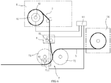
FIG. 6 is a structure diagram of a second feeding device additionally disposed inFIG. 1 . - In order to represent the technical solution of the present invention more clearly, the present invention will be explained in details with reference to the accompanying drawings
FIG. 1 to FIG. 6 hereinafter. It is to be understood that the detailed embodiments described in the description are only intended to interpret the present invention, rather than to define the protection scope of the present invention. - The present invention relates to a rolling method for a long plastic layer with an embossing in register with a pattern, comprising a feeding step of feeding a
plastic layer 3 to be rolled into oppositely rollingrollers 7, theplastic layer 3 being printed with continuous unit patterns; and a rolling step of hot rolling an embossing on theplastic layer 3. - In the feeding step, a front side of the
plastic layer 3 is adjacent to anembossing roller 71 of theoppositely rolling rollers 7, and anembossed pattern 712 disposed around an outer circle of theembossing roller 71 corresponds to apattern 32 of one unit pattern on theplastic layer 3. Optionally, a spread length of theembossed pattern 712 disposed around the outer circle of theembossing roller 71 is 1.01 to 1.5 times of the length a of one unit pattern on theplastic layer 3 before stretching. In a lateral direction, the width of theplastic layer 3 changes little after the stretching, and a deviation of the embossing in a width direction is hard to be visually noticed and can be neglected. Optionally, the width of theembossed pattern 712 on the outer circle of theembossing roller 71 is 0.95-1 times of the width of the unit pattern on theplastic layer 3 before stretching. - In the rolling step, a longitudinal deviation of the embossing is adjusted. First, the longitudinal deviation between the
embossed pattern 712 on theembossing roller 71 and thecorresponding pattern 32 on theplastic layer 3 during rolling is detected, and a feeding tension of theplastic layer 3 is adjusted according to the longitudinal deviation, so as to adjust a stretching length of theplastic layer 3 before rolling, so that the longitudinal deviation in subsequent rolling is reduced until theembossed pattern 712 is longitudinally in register with thecorresponding pattern 32 on theplastic layer 3 during rolling. - The longitudinal deviation of the embossing is measured by a distance difference or a time difference between a detected
preset part 31 on each unit pattern of theplastic layer 3 and a detectedcorresponding part 711 on theembossing roller 71 corresponding to thepreset part 31. Optionally, the adjusting step includes detecting a position of thepreset part 31 on each unit pattern of theplastic layer 3 and detecting a position of thecorresponding part 711 on theembossing roller 71 corresponding to thepreset part 31 at the same time. When thepreset part 31 is detected to be ahead of thecorresponding part 711, increase the feeding tension of theplastic layer 3 to increase the stretching length of theplastic layer 3 before rolling, so as to reduce an ahead value of thepreset part 31 in subsequent rolling until the deviation between thepreset part 31 and thecorresponding part 711 is zero, so that the embossing hot-rolled on theplastic layer 3 is longitudinally in register with thecorresponding pattern 32 on theplastic layer 3. When thepreset part 31 is detected to be lagging behind thecorresponding part 711, decrease the feeding tension of theplastic layer 3 to decrease the stretching length of theplastic layer 3 before rolling, so as to increase a lagged value of thepreset part 31 in the subsequent rolling until the deviation between thepreset part 31 and thecorresponding part 711 is zero, so that the embossing hot-rolled on theplastic layer 3 is longitudinally in register with thecorresponding pattern 32 on theplastic layer 3. Certainly, the register mentioned herein refers to register in a deviation range hard to be visually noticed, for example, the deviation is 0-2mm and is preferably 0-0.5mm. - Optionally, a heating temperature in the rolling step ranges from 85°C to 250°C.
- During the process of adjusting the longitudinal deviation of the embossing in the rolling step, a lateral deviation of the pattern is further adjusted. When the lateral deviation is detected to be existing between the
pattern 32 on theplastic layer 3 and theembossed pattern 712 on theembossing roller 71, theplastic layer 3 or theembossing roller 71 is moved along a lateral direction, so that thepattern 32 on the plastic layer is in register with theembossed pattern 712 around the outer circle of theembossing roller 71 on the lateral direction. - The
plastic layer 3 may either be a transparent plastic layer, or a non-transparent plastic layer. When the plastic layer is a transparent plastic layer, the continuous unit patterns may either be printed in the front side or the back side of the transparent plastic layer; and when the plastic layer is a non-transparent plastic layer, the continuous unit patterns are printed in the front side of the transparent plastic layer. - Further, the
plastic layer 3 further comprises aplastic base layer 5. Theplastic base layer 5 is delivered to theoppositely rolling rollers 7 simultaneously in the feeding step, and theplastic base layer 5 is located at the back side of theplastic layer 3. - A rolling device for implementing the rolling method for the long plastic layer comprises: a
first feeding device 4 for carrying theplastic layer 3, theoppositely rolling rollers 7 including theembossing roller 71 and abacking roller 72, acontrol device 10 for controlling thefirst feeding device 4 and theoppositely rolling rollers 7, a detectingdevice 8 for detecting the longitudinal deviation between theembossed pattern 712 on theembossing roller 71 and thecorresponding pattern 32 on theplastic layer 3 during rolling, and atension controller 41 disposed on thefirst feeding device 4. Theplastic layer 3 enters theoppositely rolling rollers 7 from thefirst feeding device 4, and the front side of theplastic layer 3 is adjacent to theembossing roller 71. As described in the foregoing rolling method for the long plastic layer, theembossed pattern 712 disposed around the outer circle of theembossing roller 71 corresponds to thepattern 32 of one unit pattern on theplastic layer 3. Optionally, the spread length of theembossed pattern 712 disposed around the outer circle of theembossing roller 71 is 1.01 to 1.5 times of the length a of one unit pattern on theplastic layer 3 before stretching. When theplastic layer 3 on thefirst feeding device 4 is mechanically transferred or manually fed to theoppositely rolling rollers 7, theoppositely rolling rollers 7 will have a tensile force of rolling theplastic layer 3 into theoppositely rolling rollers 7. When the detectingdevice 8 detects that the longitudinal deviation appears between theembossed pattern 712 on theembossing roller 71 and thecorresponding pattern 32 on theplastic layer 3, thecontrol device 10 controls thetension controller 41 to adjust the tension of theplastic layer 3 between thefirst feeding device 4 and theoppositely rolling rollers 7 according to the longitudinal deviation, so as to adjust the stretching length of theplastic layer 3 before rolling, thereby decreasing the longitudinal deviation during the subsequent rolling until theembossed pattern 712 is in register with thecorresponding pattern 32 on theplastic layer 3 during rolling. Thus, the embossing hot-rolled on theplastic layer 3 is longitudinally in register with thecorresponding pattern 32 on theplastic layer 3. Optionally, the detecting device comprises afirst sensor 81 for detecting the position of thepreset part 31 in each unit pattern on theplastic layer 3 and asecond sensor 82 for detecting the position of thecorresponding part 711 on theembossing roller 71 corresponding to thepreset part 31. Thecontrol device 10 uses a distance difference or a time difference of signals detected by the twosensors first feeding device 4 for feeding in theplastic layer 3, so as to adjust the stretching length of theplastic layer 3 before the rolling, so that the longitudinal deviation in the subsequent rolling is reduced until theembossed pattern 712 is longitudinally in register with thecorresponding pattern 32 on theplastic layer 3 during rolling. Optionally, thefirst sensor 81 is a color mark sensor or an image sensor, and thesecond sensor 82 is a position sensor, a displacement sensor, or a rotation speed sensor. A magnetic powder brake is adopted as thetension controller 41, and is disposed on afeed axle 42 of thefirst feeding device 4. - The
preset part 31 is preferably a partial pattern of a certain part on each unit pattern of theplastic layer 3 or is preferably a chromatic printing line (may either be a black chromatic line, or a color chromatic line in other colors) at the side of theplastic layer 3. A color mark sensor is adopted as thefirst sensor 81, thecorresponding part 711 is a magnetic block disposed at an end face of theembossing roller 71, and a Hall sensor is adopted as thesecond sensor 82. Theembossed pattern 712 on theembossing roller 71 corresponding to the magnetic block corresponds to the pattern on theplastic layer 3 corresponding to thepreset part 31. - In the lateral direction, the width of the
plastic layer 3 changes little after the stretching, and the deviation of the embossing in the width direction is hard to be visually noticed and can be neglected. Optionally, the width of theembossed pattern 712 on the outer circle of theembossing roller 71 is 0.95-1 times of the width of the unit pattern on theplastic layer 3 before stretching. To prevent theplastic layer 3 from deviation during feeding, alateral rectification device 9 may be disposed. Thelateral rectification device 9 includes athird sensor 91 for detecting a lateral deviation of the unit pattern on theplastic layer 3 and alateral transmission device 92 for making thefirst feeding device 4 move along the lateral direction. Thecontrol device 10 controls thelateral transmission device 92 according to the lateral deviation of the unit pattern on theplastic layer 3 detected by thethird sensor 91, so as to make thefirst feeding device 4 move along the lateral direction correspondingly, so that thepattern 32 on theplastic layer 3 is in register with theembossed pattern 712 around the outer circle of theembossing roller 71 on the lateral direction. During practical application, asecond feeding device 14 for feeding aplastic base layer 5 in theoppositely rolling rollers 7 may also be additionally disposed. Theplastic base layer 5 is adjacent to thebacking roller 72 and is hot-rolled on the back side of theplastic layer 3 by theembossing roller 71 and thebacking roller 72. - The long plastic layer with the embossing in register with the pattern manufactured using the foregoing rolling method comprises the
plastic layer 3, and the embossing hot-rolled on theplastic layer 3 is in register with thepattern 32 on theplastic layer 3. Optionally, thelong plastic layer 3 further comprises aplastic base layer 5 hot-rolled to the back side of theplastic layer 3. - The long plastic layer according to the foregoing technical solutions may either be bonded on the surface of a foaming board, a laminated board, or a wood-plastic board to form a composite board, or be hot-pressed together with the
plastic base layer 5 and then is directly paved on a floor for use. - The plastic layer and the plastic base layer according to the foregoing solutions of the present invention refer to a PVC material layer, and certainly may also refer to other thermoplastic layer with stretchability or other materials having similar functions.
Claims (15)
- A rolling method for a long plastic layer with an embossing in register with a pattern, comprising:a feeding step of feeding a plastic layer (3) to be rolled into oppositely rolling rollers (7), the plastic layer (3) being printed with continuous unit patterns; anda rolling step of hot rolling an embossing on the plastic layer (3);in the feeding step, a front side of the plastic layer (3) being adjacent to an embossing roller (71) of the oppositely rolling rollers (7), and an embossed pattern (712) disposed around an outer circle of the embossing roller (71) being corresponding to a pattern (32) of one unit pattern on the plastic layer (3),wherein a longitudinal deviation of the embossing is adjusted in the rolling step, an adjusting step comprises detecting the longitudinal deviation between the embossed pattern (712) on the embossing roller (71) and the corresponding pattern (32) on the plastic layer (3) during rolling and adjusting a feeding tension of the plastic layer (3) according to the longitudinal deviation, so as to adjust a stretching length of the plastic layer (3) before rolling, so that the longitudinal deviation in subsequent rolling is reduced until the embossed pattern (712) is longitudinally in register with the corresponding pattern (32) on the plastic layer (3) during rolling.
- The rolling method for the long plastic layer according to claim 1, wherein the adjusting step comprises detecting a position of a preset part (31) on each unit pattern of the plastic layer (3) and detecting a position of a corresponding part (711) on the embossing roller (71) corresponding to the preset part (31) at the same time, when the preset part (31) is detected to be ahead of the corresponding part (711), increase the feeding tension of the plastic layer (3) to increase the stretching length of the plastic layer (3) before rolling, so as to reduce an ahead value of the preset part (31) in subsequent rolling until a deviation between the preset part (31) and the corresponding part (711) is zero, so that the embossing hot-rolled on the plastic layer (3) is longitudinally in register with the corresponding pattern (32) on the plastic layer (3); and when the preset part (31) is detected to be lagging behind the corresponding part (711), decrease the feeding tension of the plastic layer (3) to decrease the stretching length of the plastic layer (3) before rolling, so as to increase a lagged value of the preset part (31) in the subsequent rolling until the deviation between the preset part (31) and the corresponding part (711) is zero, so that the embossing hot-rolled on the plastic layer (3) is longitudinally in register with the corresponding pattern (32) on the plastic layer (3).
- The rolling method for the long plastic layer according to claim 1, wherein a spread length of the embossed pattern (712) disposed around the outer circle of the embossing roller (71) is 1.01 to 1.5 times of a length (a) of one unit pattern on the plastic layer (3) before stretching; and a heating temperature in the rolling step ranges from 85°C to 250°C.
- The rolling method for the long plastic layer according to claim 1, wherein in the rolling step, the longitudinal deviation of the embossing is measured by a distance difference or a time difference between a detected preset part (31) on each unit pattern of the plastic layer (3) and a detected corresponding part (711) on the embossing roller (71) corresponding to the preset part (31).
- The rolling method for the long plastic layer according to any one of claims 1 to 4, wherein during the process of adjusting the longitudinal deviation of the embossing in the rolling step, a lateral deviation of the pattern is further adjusted, and when a lateral deviation is detected to be existing between the pattern (32) on the plastic layer (3) and the embossed pattern (712) on the embossing roller (71), the plastic layer (3) or the embossing roller (71) is moved along a lateral direction, so that the pattern (32) on the plastic layer (3) is in register with the embossed pattern (712) around the outer circle of the embossing roller (71) on the lateral direction.
- The rolling method for the long plastic layer according to claim 5, further comprising a plastic base layer (5), wherein the plastic base layer (5) is delivered to the oppositely rolling rollers (7) simultaneously in the feeding step, and the plastic base layer (5) is located at a back side of the plastic layer (3).
- A rolling device for implementing the rolling method for the long plastic layer according to claims 1, 2, 3, or 4, comprising: a first feeding device (4) for carrying the plastic layer (3), the oppositely rolling rollers (7) including the embossing roller (71) and a backing roller (72), and a control device (10) for controlling the first feeding device (4) and the oppositely rolling rollers (7); the plastic layer (3) entering the oppositely rolling rollers (7) from the first feeding device (4); and the front side of the plastic layer (3) being adjacent to the hot embossing roller (71);
wherein the rolling device further comprises a detecting device (8) for detecting the longitudinal deviation between the embossed pattern (712) on the embossing roller (71) and the corresponding pattern (32) on the plastic layer (3) during rolling, and a tension controller (41) disposed on the first feeding device (4); when the detecting device (8) detects that the longitudinal deviation appears between the embossed pattern (712) on the embossing roller (71) and the corresponding pattern (32) on the plastic layer (3), the control device (10) controls the tension controller (41) to adjust the tension of the plastic layer (3) between the first feeding device (4) and the oppositely rolling rollers (7) according to the longitudinal deviation, so as to adjust the stretching length of the plastic layer (3) before rolling, so that the longitudinal deviation in subsequent rolling is reduced until the embossed pattern (712) is in register with the corresponding pattern (32) on the plastic layer (3) during rolling, and the embossing hot-rolled on the plastic layer (3) is longitudinally in register with the corresponding pattern (32) on the plastic layer (3). - The rolling device according to claim 7, wherein the control device (10) controls a heating temperature to be between 85°C and 250 °C through controlling a hot medium flowing into the oppositely rolling rollers (7); and a spread length of the embossed pattern (712) disposed around the outer circle of the embossing roller (71) is 1.01 to 1.5 times of a length (a) of one unit pattern on the plastic layer (3) before stretching.
- The rolling device according to claim 7, wherein the detecting device (8) comprises a first sensor (81) for detecting a position of a preset part (31) in each unit pattern on the plastic layer (3) and a second sensor (82) for detecting a position of a corresponding part (711) on the embossing roller (71) corresponding to the preset part (31), the control device (10) uses a distance difference or a time difference of signals detected by the two sensors (81, 82) as the longitudinal deviation of the embossing in the rolling step to control the tension of the plastic layer between the first feeding device (4) and the oppositely rolling rollers (7), so as to adjust the stretching length of the plastic layer (3) before rolling, so that the longitudinal deviation in subsequent rolling is reduced until the embossed pattern (712) is longitudinally in register with the corresponding pattern (32) on the plastic layer (3) during rolling.
- The rolling device according to claim 9, wherein the first sensor (81) is a color mark sensor or an image sensor, and the second sensor (82) is a position sensor, a displacement sensor, or a rotation speed sensor.
- The rolling device according to any one of claims 7 to 10, wherein a magnetic powder brake is adopted as the tension controller (41) and is disposed on a feed axle (42) of the first feeding device (4).
- The rolling device according to any one of claims 7 to 10, further comprising a lateral rectification device (9), wherein the lateral rectification device (9) comprises a third sensor (91) for detecting a lateral deviation of the unit pattern on the plastic layer (3) and a lateral transmission device (92) for making the first feeding device (4) move along a lateral direction, and the control device (10) controls the lateral transmission device (92) according to the lateral deviation of the unit pattern on the plastic layer (3) detected by the third sensor (91), so as to make the first feeding device (4) move along the lateral direction correspondingly, so that the pattern (32) on the plastic layer (3) is in register with the embossed pattern (712) around the outer circle of the embossing roller (71) on the lateral direction.
- The rolling device according to any one of claims 7 to 10, further comprising a second feeding device (14) for feeding a plastic base layer (5) in the oppositely rolling rollers (7), wherein the plastic base layer (5) is adjacent to the backing roller (72) and is hot-rolled to a back side of the plastic layer (3) by the embossing roller (71) and the backing roller (72).
- A long plastic layer with an embossing in register with a pattern manufactured by the rolling method according to any one of claims 1 to 4, comprising the plastic layer (3), wherein the embossing hot-rolled on the plastic layer (3) is in register with the pattern (32) on the plastic layer (3).
- The long plastic layer according to claim 14, further comprising a plastic base layer (5) hot-rolled to a back side of the plastic layer (3).
Priority Applications (2)
| Application Number | Priority Date | Filing Date | Title |
|---|---|---|---|
| EP21199324.1A EP3957464A1 (en) | 2016-06-15 | 2016-09-21 | Long plastic layer with embossing in register with pattern and rolling method and device therefor |
| PL16189834T PL3257653T3 (en) | 2016-06-15 | 2016-09-21 | Long plastic layer embossed with pattern matching and the way it is rolled and the device for rolling it |
Applications Claiming Priority (1)
| Application Number | Priority Date | Filing Date | Title |
|---|---|---|---|
| CN201610421191.8A CN105904823A (en) | 2016-06-15 | 2016-06-15 | Long plastic layer with coincident embossing and pattern and rolling method and equipment |
Related Child Applications (2)
| Application Number | Title | Priority Date | Filing Date |
|---|---|---|---|
| EP21199324.1A Division-Into EP3957464A1 (en) | 2016-06-15 | 2016-09-21 | Long plastic layer with embossing in register with pattern and rolling method and device therefor |
| EP21199324.1A Division EP3957464A1 (en) | 2016-06-15 | 2016-09-21 | Long plastic layer with embossing in register with pattern and rolling method and device therefor |
Publications (2)
| Publication Number | Publication Date |
|---|---|
| EP3257653A1 true EP3257653A1 (en) | 2017-12-20 |
| EP3257653B1 EP3257653B1 (en) | 2021-11-03 |
Family
ID=56751150
Family Applications (2)
| Application Number | Title | Priority Date | Filing Date |
|---|---|---|---|
| EP16189834.1A Active EP3257653B1 (en) | 2016-06-15 | 2016-09-21 | Long plastic layer with embossing in register with pattern and rolling method and device therefor |
| EP21199324.1A Pending EP3957464A1 (en) | 2016-06-15 | 2016-09-21 | Long plastic layer with embossing in register with pattern and rolling method and device therefor |
Family Applications After (1)
| Application Number | Title | Priority Date | Filing Date |
|---|---|---|---|
| EP21199324.1A Pending EP3957464A1 (en) | 2016-06-15 | 2016-09-21 | Long plastic layer with embossing in register with pattern and rolling method and device therefor |
Country Status (7)
| Country | Link |
|---|---|
| US (2) | US11633904B2 (en) |
| EP (2) | EP3257653B1 (en) |
| CN (2) | CN112172298A (en) |
| AU (2) | AU2016231533A1 (en) |
| CA (1) | CA3062994A1 (en) |
| PL (1) | PL3257653T3 (en) |
| WO (1) | WO2017215045A1 (en) |
Cited By (1)
| Publication number | Priority date | Publication date | Assignee | Title |
|---|---|---|---|---|
| CN107458008A (en) * | 2017-07-26 | 2017-12-12 | 佛山市顺德区飞友自动化技术有限公司 | Ventilated membrane longitudinal stretching casting machine |
Families Citing this family (9)
| Publication number | Priority date | Publication date | Assignee | Title |
|---|---|---|---|---|
| CN112172299A (en) * | 2016-06-15 | 2021-01-05 | 浙江天振科技股份有限公司 | Long decorative material with emboss and pattern coincident, and rolling method and equipment |
| EP3516130B1 (en) | 2016-09-23 | 2023-05-10 | Shaw Industries Group, Inc. | Resilient flooring product and methods of making same |
| CN106985370A (en) * | 2017-05-25 | 2017-07-28 | 孟杰 | A kind of PVC material embossing method |
| CN109940867B (en) * | 2017-12-20 | 2021-04-06 | 无锡市博宇塑机有限公司 | Improved synchronous register system for plastic floor |
| CN109795006A (en) * | 2019-01-31 | 2019-05-24 | 财纳福诺木业(中国)有限公司 | Floor embosses control method to flower to flower Embosser and floor |
| CN110644727A (en) | 2019-09-25 | 2020-01-03 | 浙江永裕竹业股份有限公司 | Online synchronous register co-extrusion SPC floor and production process thereof |
| US20230347567A1 (en) * | 2022-04-27 | 2023-11-02 | Not Wood Inc. | Construction components and systems fabricated using extruded materials |
| CN118410630B (en) * | 2024-04-24 | 2024-09-13 | 平湖市新恒升新材料股份有限公司 | A method and system for optimizing the thermoforming process of PP sheets |
| CN119159792B (en) * | 2024-08-27 | 2025-08-05 | 吾优新材料科技(江苏)有限公司 | A variable lamination roller used in decorative film processing and production |
Citations (9)
| Publication number | Priority date | Publication date | Assignee | Title |
|---|---|---|---|---|
| US5122212A (en) | 1989-10-27 | 1992-06-16 | American Biltrite, Inc. | Method and apparatus for the manufacture of printed and embossed floor covering |
| JPH06215371A (en) * | 1992-05-25 | 1994-08-05 | Tokin Corp | Apparatus for production and production of magnetic recording medium |
| JPH06297570A (en) * | 1993-04-20 | 1994-10-25 | Dainippon Printing Co Ltd | Decorative sheet manufacturing method |
| JPH07276497A (en) * | 1994-04-14 | 1995-10-24 | Dainippon Printing Co Ltd | Decorative sheet manufacturing method |
| JPH0839669A (en) * | 1994-08-02 | 1996-02-13 | Dainippon Printing Co Ltd | Pattern tuning embossing register adjustment method |
| US6416607B1 (en) * | 1999-10-07 | 2002-07-09 | Industrial Technology Research Institute | Automatic embossing device for plastic floor tile |
| CN1420025A (en) | 2001-11-15 | 2003-05-28 | Lg化学株式会社 | Long size floor decoration material with consistent printed pattern and embossed pattern and mfg. method thereof |
| DE102006019591B3 (en) * | 2006-04-27 | 2007-05-31 | Lsf Maschinen- Und Anlagenbau Gmbh & Co. Kg | Method for stamping printed strip material, involves fixing plastic coating in rapport with repeated pattern on strip material |
| US20080122129A1 (en) * | 2004-08-13 | 2008-05-29 | Pekka Koivukunnas | Embossing Device And A Method For Adjusting The Embossing Device |
Family Cites Families (58)
| Publication number | Priority date | Publication date | Assignee | Title |
|---|---|---|---|---|
| US2831097A (en) * | 1956-02-23 | 1958-04-15 | Malewski Theodore | Heating roller assembly for laminating, embossing, and printing machines |
| US3024154A (en) * | 1958-04-04 | 1962-03-06 | Carpenter L E Co | Method and apparatus for embossing and printing thermoplastic film and the product thereof |
| NL283324A (en) * | 1961-09-27 | |||
| US3471354A (en) * | 1964-08-19 | 1969-10-07 | Rohm & Haas | Embossing apparatus |
| US3741851A (en) * | 1970-10-07 | 1973-06-26 | Gaf Corp | Embossed foamed sheet materials |
| US3953639A (en) * | 1974-02-15 | 1976-04-27 | Armstrong Cork Company | Mechanically embossed resilient laminar floor material |
| US3959567A (en) * | 1974-09-12 | 1976-05-25 | Surface Activation Corporation | Method and apparatus for making laminates |
| US4105491A (en) * | 1975-02-21 | 1978-08-08 | Mobil Oil Corporation | Process and apparatus for the manufacture of embossed film laminations |
| US4069081A (en) * | 1976-08-04 | 1978-01-17 | Sealtran Corporation | Method for protective film lamination with curl control |
| US4312686A (en) * | 1980-02-11 | 1982-01-26 | American Biltrite Inc. | Printed and embossed floor covering and method and apparatus for its manufacture |
| FR2515569A1 (en) * | 1981-11-05 | 1983-05-06 | Marne Productions Textiles Pla | IMPRESSION MACHINE WITH PRESERVE CYLINDERS |
| WO1984001733A1 (en) * | 1982-10-25 | 1984-05-10 | Taiho Kogyo Co Ltd | Method of pressure-welding composite material |
| US4612074A (en) * | 1983-08-24 | 1986-09-16 | American Biltrite Inc. | Method for manufacturing a printed and embossed floor covering |
| US4773959A (en) * | 1983-08-24 | 1988-09-27 | American Biltrite, Inc. | Apparatus for the manufacture of printed and embossed floor covering |
| US4589942A (en) * | 1984-07-11 | 1986-05-20 | Transilwrap Company | Method for laminating a composite assembly |
| DE3920946A1 (en) * | 1989-06-27 | 1991-01-03 | Held Kurt | DEVICE FOR THE CONTINUOUS PRODUCTION OF LAMINATES |
| US5118532A (en) * | 1990-02-27 | 1992-06-02 | Vytech Industries, Inc. | Method of producing decorative vertical louver window covering material and decorative vertical louver material so produced |
| US5098507A (en) * | 1991-01-28 | 1992-03-24 | Mao Chen Chi | Relieved plastic floor tile rolling press with an automatic alignment device |
| JPH05508375A (en) * | 1991-05-03 | 1993-11-25 | イーストマン・コダック・カンパニー | Web wrapping control method |
| CN2210082Y (en) * | 1994-09-26 | 1995-10-18 | 褚汉林 | Cylinder like double surface continuously embossing (by rolling or pressing) apparatus for plastic film |
| JP3154931B2 (en) * | 1995-09-22 | 2001-04-09 | 凸版印刷株式会社 | Embossed sheet, laminate using the same, and method of manufacturing the same |
| CN2249280Y (en) * | 1995-12-19 | 1997-03-12 | 陈清文 | Automatic embossing device for plastic floor tiles |
| CA2282853C (en) * | 1998-01-30 | 2002-01-01 | James H. Stauffacher | Apparatus and method for embossing and printing elongated substrates |
| US20030072919A1 (en) * | 2001-09-13 | 2003-04-17 | Frank Watts | Surface covering having differential gloss in-register and method of making |
| ITMI20020153A1 (en) * | 2002-01-29 | 2003-07-29 | Thermo Engineering Srl | CONTINUOUS SYSTEM FOR PLASTIC LAMINATES INCLUDING MULTILAYER IN COLD PRESS |
| WO2004028794A2 (en) * | 2002-09-24 | 2004-04-08 | Schneller, Inc. | Dimensionally stable laminate with removable web carrier and method of manufacture |
| US20050029704A1 (en) * | 2003-03-05 | 2005-02-10 | Tilia International, Inc. | Method for manufacturing a sealable bag having an indicia for use in vacuum packaging |
| US7165959B2 (en) * | 2003-09-09 | 2007-01-23 | 3M Innovative Properties Company | Apparatus and method for producing two-sided patterned webs in registration |
| US20050124242A1 (en) * | 2003-12-03 | 2005-06-09 | Jean Norvell | Novel polymer films and textile laminates containing such polymer films |
| US20070116929A1 (en) * | 2003-12-26 | 2007-05-24 | Dai Nippon Printing Co., Ltd. | Embossed release paper for synthetic leather production and support therefor, and synthetic leather using the release paper and process for producing the synthetic leather |
| JP4486373B2 (en) * | 2004-02-10 | 2010-06-23 | カシオマイクロニクス株式会社 | LAMINATING METHOD AND LAMINATING APPARATUS USING THE METHOD |
| JP4883008B2 (en) * | 2005-11-04 | 2012-02-22 | コニカミノルタオプト株式会社 | Cellulosic resin film, method for producing cellulose resin film, antireflection film, polarizing plate and liquid crystal display device |
| EP2089458B1 (en) * | 2006-09-28 | 2011-09-21 | 3M Innovative Properties Company | Method, system and its use for controlling curl in multi-layer webs |
| US20080210366A1 (en) * | 2007-03-02 | 2008-09-04 | Formosa Saint Jose Corp. | Method of making a mat |
| US7964243B2 (en) * | 2007-04-30 | 2011-06-21 | S.D. Warren Company | Materials having a textured surface and methods for producing same |
| CN101932446B (en) * | 2007-11-27 | 2014-03-26 | 日本瑞翁株式会社 | Stretched film, method for producing same, and liquid crystal display device |
| WO2010021133A1 (en) * | 2008-08-20 | 2010-02-25 | 日本カーバイド工業株式会社 | Optical sheet manufacturing device and optical sheet manufacturing method |
| KR101590102B1 (en) * | 2009-05-07 | 2016-01-29 | 삼성전자 주식회사 | Roll to roll patterning apparatus and patterning system having the same |
| CN101623909B (en) * | 2009-08-05 | 2012-02-15 | 东莞市兄奕塑胶制品有限公司 | Manufacturing method and processing equipment of furniture wood-grain-like edge banding strip |
| CN102101411B (en) * | 2009-12-16 | 2015-02-25 | 东莞市悠悠美居家居制造有限公司 | Plastic decorative sheet, preparation method thereof and special relief hot-pressing roller |
| US9067357B2 (en) * | 2010-09-10 | 2015-06-30 | The Procter & Gamble Company | Method for deforming a web |
| US8628711B2 (en) * | 2010-10-13 | 2014-01-14 | Nan Ya Plastics Corporation | In-mold label and method for producing the same |
| US9120670B2 (en) * | 2011-02-24 | 2015-09-01 | Hoowaki, Llc | System and method for extruding parts having microstructures |
| CN202053674U (en) * | 2011-05-14 | 2011-11-30 | 广东金玉兰包装机械有限公司 | Transfer-printing pattern positioning and embossing machine |
| WO2012174204A2 (en) * | 2011-06-17 | 2012-12-20 | Fiberweb, Inc. | Vapor permeable, substantially water impermeable multilayer article |
| US9765459B2 (en) * | 2011-06-24 | 2017-09-19 | Fiberweb, Llc | Vapor-permeable, substantially water-impermeable multilayer article |
| KR20140066770A (en) * | 2011-09-20 | 2014-06-02 | 애버리 데니슨 코포레이션 | Embossed thermoplastic label |
| EP2636524B1 (en) * | 2012-03-05 | 2014-12-31 | Rodolfo Comerio S.r.l. | Process and apparatus for registered embossing of extensible printed film or of a laminate comprising an extensible printed film |
| WO2013140453A1 (en) * | 2012-03-22 | 2013-09-26 | コニカミノルタ株式会社 | Method for manufacturing long stretched film, and device for manufacturing long stretched film |
| CN102814977B (en) * | 2012-07-20 | 2015-03-25 | 新乡市鼎鑫机械有限公司 | On-line embossing method for PVC floor and special production apparatus used therein |
| PL3524429T3 (en) * | 2014-07-31 | 2021-07-19 | Unilin, Bv | A method of producing a product in the form of a floor covering |
| MX2017003322A (en) * | 2014-09-12 | 2017-11-22 | Procter & Gamble | Method of making nonwoven material having discrete three-dimensional deformations with wide base openings that are bonded to additional layer. |
| CN106715133B (en) * | 2014-09-29 | 2019-05-31 | 塔吉特Gdl公司 | Method for producing a surface covering with an embossed printed surface |
| WO2016184581A1 (en) * | 2015-05-21 | 2016-11-24 | Olbrich Gmbh | Method and device for producing a material, in particular a laminated material, which is registered embossed |
| CN105599420B (en) * | 2016-01-29 | 2019-02-05 | 广州迪滔日用品制造有限公司 | Soft material printing positioning embossing production process and equipment |
| CN205767912U (en) * | 2016-06-15 | 2016-12-07 | 朱彩琴 | Emboss the long ornament materials and process equipment overlapped with decorative pattern |
| CN205800445U (en) * | 2016-06-15 | 2016-12-14 | 朱彩琴 | Emboss the long plastic layer and roll unit overlapped with decorative pattern |
| CN112172299A (en) * | 2016-06-15 | 2021-01-05 | 浙江天振科技股份有限公司 | Long decorative material with emboss and pattern coincident, and rolling method and equipment |
-
2016
- 2016-06-15 CN CN202010923605.3A patent/CN112172298A/en active Pending
- 2016-06-15 CN CN201610421191.8A patent/CN105904823A/en active Pending
- 2016-06-30 CA CA3062994A patent/CA3062994A1/en not_active Abandoned
- 2016-06-30 WO PCT/CN2016/088034 patent/WO2017215045A1/en not_active Ceased
- 2016-09-20 US US15/270,738 patent/US11633904B2/en active Active
- 2016-09-21 AU AU2016231533A patent/AU2016231533A1/en active Pending
- 2016-09-21 AU AU2016102397A patent/AU2016102397A4/en not_active Ceased
- 2016-09-21 EP EP16189834.1A patent/EP3257653B1/en active Active
- 2016-09-21 EP EP21199324.1A patent/EP3957464A1/en active Pending
- 2016-09-21 PL PL16189834T patent/PL3257653T3/en unknown
-
2023
- 2023-03-13 US US18/182,654 patent/US12186973B2/en active Active
Patent Citations (9)
| Publication number | Priority date | Publication date | Assignee | Title |
|---|---|---|---|---|
| US5122212A (en) | 1989-10-27 | 1992-06-16 | American Biltrite, Inc. | Method and apparatus for the manufacture of printed and embossed floor covering |
| JPH06215371A (en) * | 1992-05-25 | 1994-08-05 | Tokin Corp | Apparatus for production and production of magnetic recording medium |
| JPH06297570A (en) * | 1993-04-20 | 1994-10-25 | Dainippon Printing Co Ltd | Decorative sheet manufacturing method |
| JPH07276497A (en) * | 1994-04-14 | 1995-10-24 | Dainippon Printing Co Ltd | Decorative sheet manufacturing method |
| JPH0839669A (en) * | 1994-08-02 | 1996-02-13 | Dainippon Printing Co Ltd | Pattern tuning embossing register adjustment method |
| US6416607B1 (en) * | 1999-10-07 | 2002-07-09 | Industrial Technology Research Institute | Automatic embossing device for plastic floor tile |
| CN1420025A (en) | 2001-11-15 | 2003-05-28 | Lg化学株式会社 | Long size floor decoration material with consistent printed pattern and embossed pattern and mfg. method thereof |
| US20080122129A1 (en) * | 2004-08-13 | 2008-05-29 | Pekka Koivukunnas | Embossing Device And A Method For Adjusting The Embossing Device |
| DE102006019591B3 (en) * | 2006-04-27 | 2007-05-31 | Lsf Maschinen- Und Anlagenbau Gmbh & Co. Kg | Method for stamping printed strip material, involves fixing plastic coating in rapport with repeated pattern on strip material |
Cited By (1)
| Publication number | Priority date | Publication date | Assignee | Title |
|---|---|---|---|---|
| CN107458008A (en) * | 2017-07-26 | 2017-12-12 | 佛山市顺德区飞友自动化技术有限公司 | Ventilated membrane longitudinal stretching casting machine |
Also Published As
| Publication number | Publication date |
|---|---|
| US20170361521A1 (en) | 2017-12-21 |
| EP3257653B1 (en) | 2021-11-03 |
| CN105904823A (en) | 2016-08-31 |
| PL3257653T3 (en) | 2022-02-28 |
| US20230211543A1 (en) | 2023-07-06 |
| US11633904B2 (en) | 2023-04-25 |
| US12186973B2 (en) | 2025-01-07 |
| AU2016231533A1 (en) | 2018-01-18 |
| CN112172298A (en) | 2021-01-05 |
| WO2017215045A1 (en) | 2017-12-21 |
| CA3062994A1 (en) | 2019-12-03 |
| AU2016102397A4 (en) | 2019-05-09 |
| EP3957464A1 (en) | 2022-02-23 |
Similar Documents
| Publication | Publication Date | Title |
|---|---|---|
| US12138848B2 (en) | Long decorative material with embossing in register with pattern and rolling method and device therefor | |
| US12186973B2 (en) | Long plastic layer with embossing in register with pattern and rolling method and device therefor | |
| CN205767912U (en) | Emboss the long ornament materials and process equipment overlapped with decorative pattern | |
| US20240246318A1 (en) | On-line synchronous registering co-extrusion spc floor and production process therefor | |
| CN105711226A (en) | Four-roll calendering and draping production device for PVC plastic floor surface film attachment | |
| CN205800445U (en) | Emboss the long plastic layer and roll unit overlapped with decorative pattern | |
| CN107806221A (en) | Plastic floor with synchronization to floral diagram line | |
| CN106945450A (en) | The manufacture craft of composite membrane product with colored convex-concave pattern | |
| CN109955577A (en) | The preparation method of PVC plastic decorative panel | |
| CN206678523U (en) | The equipment for coating film on PVC overlay films floor | |
| CN212313028U (en) | Synchronous register plate and synchronous register system for plate based on screen printing technology | |
| CN109703000A (en) | A kind of five roller of PVC is synchronized to embossing device | |
| CN103407280A (en) | Wall cloth producing system | |
| CN203792401U (en) | Fast colorful face line pressing machine | |
| CN207072074U (en) | Calender | |
| KR101478559B1 (en) | Chalkboard for magnetic sticking manufacturing apparatus | |
| CN209794602U (en) | Rolling equipment on PVC floor | |
| CN206186466U (en) | Pad pasting panel | |
| CN206245658U (en) | A kind of self-adhesive composite plastic floor | |
| CN202138022U (en) | Biaxially oriented polypropylene base film polished by double electric composite paper |
Legal Events
| Date | Code | Title | Description |
|---|---|---|---|
| STAA | Information on the status of an ep patent application or granted ep patent |
Free format text: STATUS: EXAMINATION IS IN PROGRESS |
|
| PUAI | Public reference made under article 153(3) epc to a published international application that has entered the european phase |
Free format text: ORIGINAL CODE: 0009012 |
|
| 17P | Request for examination filed |
Effective date: 20160921 |
|
| AK | Designated contracting states |
Kind code of ref document: A1 Designated state(s): AL AT BE BG CH CY CZ DE DK EE ES FI FR GB GR HR HU IE IS IT LI LT LU LV MC MK MT NL NO PL PT RO RS SE SI SK SM TR |
|
| AX | Request for extension of the european patent |
Extension state: BA ME |
|
| RIC1 | Information provided on ipc code assigned before grant |
Ipc: B32B 37/20 20060101ALI20180523BHEP Ipc: B44B 5/00 20060101ALI20180523BHEP Ipc: B44B 5/02 20060101ALI20180523BHEP Ipc: B29C 59/04 20060101AFI20180523BHEP Ipc: B32B 38/06 20060101ALN20180523BHEP Ipc: B29L 7/00 20060101ALN20180523BHEP Ipc: B44C 1/24 20060101ALI20180523BHEP |
|
| RIC1 | Information provided on ipc code assigned before grant |
Ipc: B29L 7/00 20060101ALN20180612BHEP Ipc: B44C 1/24 20060101ALI20180612BHEP Ipc: B44B 5/02 20060101ALI20180612BHEP Ipc: B32B 38/06 20060101ALN20180612BHEP Ipc: B29C 59/04 20060101AFI20180612BHEP Ipc: B44B 5/00 20060101ALI20180612BHEP Ipc: B32B 37/20 20060101ALI20180612BHEP |
|
| RAP1 | Party data changed (applicant data changed or rights of an application transferred) |
Owner name: FLOORING INDUSTRIES LIMITED, SARL |
|
| GRAP | Despatch of communication of intention to grant a patent |
Free format text: ORIGINAL CODE: EPIDOSNIGR1 |
|
| STAA | Information on the status of an ep patent application or granted ep patent |
Free format text: STATUS: GRANT OF PATENT IS INTENDED |
|
| RIC1 | Information provided on ipc code assigned before grant |
Ipc: B32B 38/06 20060101ALN20210517BHEP Ipc: B29L 7/00 20060101ALN20210517BHEP Ipc: B44B 5/02 20060101ALI20210517BHEP Ipc: B44B 5/00 20060101ALI20210517BHEP Ipc: B44C 1/24 20060101ALI20210517BHEP Ipc: B32B 37/20 20060101ALI20210517BHEP Ipc: B29C 59/04 20060101AFI20210517BHEP |
|
| INTG | Intention to grant announced |
Effective date: 20210609 |
|
| GRAS | Grant fee paid |
Free format text: ORIGINAL CODE: EPIDOSNIGR3 |
|
| GRAA | (expected) grant |
Free format text: ORIGINAL CODE: 0009210 |
|
| STAA | Information on the status of an ep patent application or granted ep patent |
Free format text: STATUS: THE PATENT HAS BEEN GRANTED |
|
| AK | Designated contracting states |
Kind code of ref document: B1 Designated state(s): AL AT BE BG CH CY CZ DE DK EE ES FI FR GB GR HR HU IE IS IT LI LT LU LV MC MK MT NL NO PL PT RO RS SE SI SK SM TR |
|
| REG | Reference to a national code |
Ref country code: GB Ref legal event code: FG4D |
|
| REG | Reference to a national code |
Ref country code: AT Ref legal event code: REF Ref document number: 1443603 Country of ref document: AT Kind code of ref document: T Effective date: 20211115 Ref country code: CH Ref legal event code: EP |
|
| REG | Reference to a national code |
Ref country code: IE Ref legal event code: FG4D |
|
| REG | Reference to a national code |
Ref country code: DE Ref legal event code: R096 Ref document number: 602016065665 Country of ref document: DE |
|
| REG | Reference to a national code |
Ref country code: LT Ref legal event code: MG9D |
|
| REG | Reference to a national code |
Ref country code: NL Ref legal event code: MP Effective date: 20211103 |
|
| REG | Reference to a national code |
Ref country code: AT Ref legal event code: MK05 Ref document number: 1443603 Country of ref document: AT Kind code of ref document: T Effective date: 20211103 |
|
| PG25 | Lapsed in a contracting state [announced via postgrant information from national office to epo] |
Ref country code: RS Free format text: LAPSE BECAUSE OF FAILURE TO SUBMIT A TRANSLATION OF THE DESCRIPTION OR TO PAY THE FEE WITHIN THE PRESCRIBED TIME-LIMIT Effective date: 20211103 Ref country code: LT Free format text: LAPSE BECAUSE OF FAILURE TO SUBMIT A TRANSLATION OF THE DESCRIPTION OR TO PAY THE FEE WITHIN THE PRESCRIBED TIME-LIMIT Effective date: 20211103 Ref country code: FI Free format text: LAPSE BECAUSE OF FAILURE TO SUBMIT A TRANSLATION OF THE DESCRIPTION OR TO PAY THE FEE WITHIN THE PRESCRIBED TIME-LIMIT Effective date: 20211103 Ref country code: BG Free format text: LAPSE BECAUSE OF FAILURE TO SUBMIT A TRANSLATION OF THE DESCRIPTION OR TO PAY THE FEE WITHIN THE PRESCRIBED TIME-LIMIT Effective date: 20220203 Ref country code: AT Free format text: LAPSE BECAUSE OF FAILURE TO SUBMIT A TRANSLATION OF THE DESCRIPTION OR TO PAY THE FEE WITHIN THE PRESCRIBED TIME-LIMIT Effective date: 20211103 |
|
| PG25 | Lapsed in a contracting state [announced via postgrant information from national office to epo] |
Ref country code: IS Free format text: LAPSE BECAUSE OF FAILURE TO SUBMIT A TRANSLATION OF THE DESCRIPTION OR TO PAY THE FEE WITHIN THE PRESCRIBED TIME-LIMIT Effective date: 20220303 Ref country code: SE Free format text: LAPSE BECAUSE OF FAILURE TO SUBMIT A TRANSLATION OF THE DESCRIPTION OR TO PAY THE FEE WITHIN THE PRESCRIBED TIME-LIMIT Effective date: 20211103 Ref country code: PT Free format text: LAPSE BECAUSE OF FAILURE TO SUBMIT A TRANSLATION OF THE DESCRIPTION OR TO PAY THE FEE WITHIN THE PRESCRIBED TIME-LIMIT Effective date: 20220303 Ref country code: NO Free format text: LAPSE BECAUSE OF FAILURE TO SUBMIT A TRANSLATION OF THE DESCRIPTION OR TO PAY THE FEE WITHIN THE PRESCRIBED TIME-LIMIT Effective date: 20220203 Ref country code: NL Free format text: LAPSE BECAUSE OF FAILURE TO SUBMIT A TRANSLATION OF THE DESCRIPTION OR TO PAY THE FEE WITHIN THE PRESCRIBED TIME-LIMIT Effective date: 20211103 Ref country code: LV Free format text: LAPSE BECAUSE OF FAILURE TO SUBMIT A TRANSLATION OF THE DESCRIPTION OR TO PAY THE FEE WITHIN THE PRESCRIBED TIME-LIMIT Effective date: 20211103 Ref country code: HR Free format text: LAPSE BECAUSE OF FAILURE TO SUBMIT A TRANSLATION OF THE DESCRIPTION OR TO PAY THE FEE WITHIN THE PRESCRIBED TIME-LIMIT Effective date: 20211103 Ref country code: GR Free format text: LAPSE BECAUSE OF FAILURE TO SUBMIT A TRANSLATION OF THE DESCRIPTION OR TO PAY THE FEE WITHIN THE PRESCRIBED TIME-LIMIT Effective date: 20220204 Ref country code: ES Free format text: LAPSE BECAUSE OF FAILURE TO SUBMIT A TRANSLATION OF THE DESCRIPTION OR TO PAY THE FEE WITHIN THE PRESCRIBED TIME-LIMIT Effective date: 20211103 |
|
| PG25 | Lapsed in a contracting state [announced via postgrant information from national office to epo] |
Ref country code: SM Free format text: LAPSE BECAUSE OF FAILURE TO SUBMIT A TRANSLATION OF THE DESCRIPTION OR TO PAY THE FEE WITHIN THE PRESCRIBED TIME-LIMIT Effective date: 20211103 Ref country code: SK Free format text: LAPSE BECAUSE OF FAILURE TO SUBMIT A TRANSLATION OF THE DESCRIPTION OR TO PAY THE FEE WITHIN THE PRESCRIBED TIME-LIMIT Effective date: 20211103 Ref country code: RO Free format text: LAPSE BECAUSE OF FAILURE TO SUBMIT A TRANSLATION OF THE DESCRIPTION OR TO PAY THE FEE WITHIN THE PRESCRIBED TIME-LIMIT Effective date: 20211103 Ref country code: EE Free format text: LAPSE BECAUSE OF FAILURE TO SUBMIT A TRANSLATION OF THE DESCRIPTION OR TO PAY THE FEE WITHIN THE PRESCRIBED TIME-LIMIT Effective date: 20211103 Ref country code: DK Free format text: LAPSE BECAUSE OF FAILURE TO SUBMIT A TRANSLATION OF THE DESCRIPTION OR TO PAY THE FEE WITHIN THE PRESCRIBED TIME-LIMIT Effective date: 20211103 Ref country code: CZ Free format text: LAPSE BECAUSE OF FAILURE TO SUBMIT A TRANSLATION OF THE DESCRIPTION OR TO PAY THE FEE WITHIN THE PRESCRIBED TIME-LIMIT Effective date: 20211103 |
|
| REG | Reference to a national code |
Ref country code: DE Ref legal event code: R097 Ref document number: 602016065665 Country of ref document: DE |
|
| PLBE | No opposition filed within time limit |
Free format text: ORIGINAL CODE: 0009261 |
|
| STAA | Information on the status of an ep patent application or granted ep patent |
Free format text: STATUS: NO OPPOSITION FILED WITHIN TIME LIMIT |
|
| 26N | No opposition filed |
Effective date: 20220804 |
|
| PG25 | Lapsed in a contracting state [announced via postgrant information from national office to epo] |
Ref country code: AL Free format text: LAPSE BECAUSE OF FAILURE TO SUBMIT A TRANSLATION OF THE DESCRIPTION OR TO PAY THE FEE WITHIN THE PRESCRIBED TIME-LIMIT Effective date: 20211103 |
|
| PG25 | Lapsed in a contracting state [announced via postgrant information from national office to epo] |
Ref country code: SI Free format text: LAPSE BECAUSE OF FAILURE TO SUBMIT A TRANSLATION OF THE DESCRIPTION OR TO PAY THE FEE WITHIN THE PRESCRIBED TIME-LIMIT Effective date: 20211103 |
|
| PG25 | Lapsed in a contracting state [announced via postgrant information from national office to epo] |
Ref country code: MC Free format text: LAPSE BECAUSE OF FAILURE TO SUBMIT A TRANSLATION OF THE DESCRIPTION OR TO PAY THE FEE WITHIN THE PRESCRIBED TIME-LIMIT Effective date: 20211103 |
|
| REG | Reference to a national code |
Ref country code: CH Ref legal event code: PL |
|
| GBPC | Gb: european patent ceased through non-payment of renewal fee |
Effective date: 20220921 |
|
| PG25 | Lapsed in a contracting state [announced via postgrant information from national office to epo] |
Ref country code: IT Free format text: LAPSE BECAUSE OF FAILURE TO SUBMIT A TRANSLATION OF THE DESCRIPTION OR TO PAY THE FEE WITHIN THE PRESCRIBED TIME-LIMIT Effective date: 20211103 |
|
| P01 | Opt-out of the competence of the unified patent court (upc) registered |
Effective date: 20230428 |
|
| PG25 | Lapsed in a contracting state [announced via postgrant information from national office to epo] |
Ref country code: LU Free format text: LAPSE BECAUSE OF NON-PAYMENT OF DUE FEES Effective date: 20220921 |
|
| PG25 | Lapsed in a contracting state [announced via postgrant information from national office to epo] |
Ref country code: LI Free format text: LAPSE BECAUSE OF NON-PAYMENT OF DUE FEES Effective date: 20220930 Ref country code: IE Free format text: LAPSE BECAUSE OF NON-PAYMENT OF DUE FEES Effective date: 20220921 Ref country code: CH Free format text: LAPSE BECAUSE OF NON-PAYMENT OF DUE FEES Effective date: 20220930 |
|
| P02 | Opt-out of the competence of the unified patent court (upc) changed |
Effective date: 20230909 |
|
| PG25 | Lapsed in a contracting state [announced via postgrant information from national office to epo] |
Ref country code: GB Free format text: LAPSE BECAUSE OF NON-PAYMENT OF DUE FEES Effective date: 20220921 |
|
| PG25 | Lapsed in a contracting state [announced via postgrant information from national office to epo] |
Ref country code: HU Free format text: LAPSE BECAUSE OF FAILURE TO SUBMIT A TRANSLATION OF THE DESCRIPTION OR TO PAY THE FEE WITHIN THE PRESCRIBED TIME-LIMIT; INVALID AB INITIO Effective date: 20160921 |
|
| REG | Reference to a national code |
Ref country code: DE Ref legal event code: R081 Ref document number: 602016065665 Country of ref document: DE Owner name: UNILIN BV, BE Free format text: FORMER OWNER: FLOORING INDUSTRIES LIMITED, SARL, BERTRANGE, LU |
|
| PG25 | Lapsed in a contracting state [announced via postgrant information from national office to epo] |
Ref country code: CY Free format text: LAPSE BECAUSE OF FAILURE TO SUBMIT A TRANSLATION OF THE DESCRIPTION OR TO PAY THE FEE WITHIN THE PRESCRIBED TIME-LIMIT Effective date: 20211103 |
|
| PG25 | Lapsed in a contracting state [announced via postgrant information from national office to epo] |
Ref country code: MK Free format text: LAPSE BECAUSE OF FAILURE TO SUBMIT A TRANSLATION OF THE DESCRIPTION OR TO PAY THE FEE WITHIN THE PRESCRIBED TIME-LIMIT Effective date: 20211103 |
|
| REG | Reference to a national code |
Ref country code: BE Ref legal event code: PD Owner name: UNILIN BV; BE Free format text: DETAILS ASSIGNMENT: CHANGE OF OWNER(S), ASSIGNMENT; FORMER OWNER NAME: FLOORING INDUSTRIES LIMITED, SARL Effective date: 20240320 |
|
| PG25 | Lapsed in a contracting state [announced via postgrant information from national office to epo] |
Ref country code: TR Free format text: LAPSE BECAUSE OF FAILURE TO SUBMIT A TRANSLATION OF THE DESCRIPTION OR TO PAY THE FEE WITHIN THE PRESCRIBED TIME-LIMIT Effective date: 20211103 |
|
| PG25 | Lapsed in a contracting state [announced via postgrant information from national office to epo] |
Ref country code: MT Free format text: LAPSE BECAUSE OF FAILURE TO SUBMIT A TRANSLATION OF THE DESCRIPTION OR TO PAY THE FEE WITHIN THE PRESCRIBED TIME-LIMIT Effective date: 20211103 |
|
| PGFP | Annual fee paid to national office [announced via postgrant information from national office to epo] |
Ref country code: DE Payment date: 20250929 Year of fee payment: 10 |
|
| PGFP | Annual fee paid to national office [announced via postgrant information from national office to epo] |
Ref country code: PL Payment date: 20250904 Year of fee payment: 10 |
|
| PGFP | Annual fee paid to national office [announced via postgrant information from national office to epo] |
Ref country code: BE Payment date: 20250929 Year of fee payment: 10 |
|
| PGFP | Annual fee paid to national office [announced via postgrant information from national office to epo] |
Ref country code: FR Payment date: 20250925 Year of fee payment: 10 |