EP3256763B1 - Schirmrückschlagventil mit reduzierter hämolyse - Google Patents
Schirmrückschlagventil mit reduzierter hämolyse Download PDFInfo
- Publication number
- EP3256763B1 EP3256763B1 EP16749682.7A EP16749682A EP3256763B1 EP 3256763 B1 EP3256763 B1 EP 3256763B1 EP 16749682 A EP16749682 A EP 16749682A EP 3256763 B1 EP3256763 B1 EP 3256763B1
- Authority
- EP
- European Patent Office
- Prior art keywords
- wall portion
- check valve
- valve assembly
- annular wall
- outlet
- Prior art date
- Legal status (The legal status is an assumption and is not a legal conclusion. Google has not performed a legal analysis and makes no representation as to the accuracy of the status listed.)
- Active
Links
- 206010018910 Haemolysis Diseases 0.000 title description 3
- 230000008588 hemolysis Effects 0.000 title description 3
- 238000000926 separation method Methods 0.000 claims description 25
- 238000003466 welding Methods 0.000 claims description 9
- 239000000853 adhesive Substances 0.000 claims description 6
- 230000001070 adhesive effect Effects 0.000 claims description 6
- 239000002904 solvent Substances 0.000 claims description 6
- 230000007704 transition Effects 0.000 claims description 2
- 239000012530 fluid Substances 0.000 description 30
- 238000007789 sealing Methods 0.000 description 14
- 238000001802 infusion Methods 0.000 description 9
- 210000004027 cell Anatomy 0.000 description 8
- 210000003743 erythrocyte Anatomy 0.000 description 6
- 238000004088 simulation Methods 0.000 description 3
- 238000013459 approach Methods 0.000 description 2
- 230000000712 assembly Effects 0.000 description 2
- 238000000429 assembly Methods 0.000 description 2
- 239000010836 blood and blood product Substances 0.000 description 2
- 229940125691 blood product Drugs 0.000 description 2
- 238000005336 cracking Methods 0.000 description 2
- 230000003247 decreasing effect Effects 0.000 description 2
- 230000005484 gravity Effects 0.000 description 2
- 238000001746 injection moulding Methods 0.000 description 2
- 238000001990 intravenous administration Methods 0.000 description 2
- 239000000463 material Substances 0.000 description 2
- 238000002560 therapeutic procedure Methods 0.000 description 2
- 229920001651 Cyanoacrylate Polymers 0.000 description 1
- 239000004593 Epoxy Substances 0.000 description 1
- WQZGKKKJIJFFOK-GASJEMHNSA-N Glucose Natural products OC[C@H]1OC(O)[C@H](O)[C@@H](O)[C@@H]1O WQZGKKKJIJFFOK-GASJEMHNSA-N 0.000 description 1
- MWCLLHOVUTZFKS-UHFFFAOYSA-N Methyl cyanoacrylate Chemical compound COC(=O)C(=C)C#N MWCLLHOVUTZFKS-UHFFFAOYSA-N 0.000 description 1
- FAPWRFPIFSIZLT-UHFFFAOYSA-M Sodium chloride Chemical compound [Na+].[Cl-] FAPWRFPIFSIZLT-UHFFFAOYSA-M 0.000 description 1
- 230000001133 acceleration Effects 0.000 description 1
- 230000004913 activation Effects 0.000 description 1
- 238000004026 adhesive bonding Methods 0.000 description 1
- WQZGKKKJIJFFOK-VFUOTHLCSA-N beta-D-glucose Chemical compound OC[C@H]1O[C@@H](O)[C@H](O)[C@@H](O)[C@@H]1O WQZGKKKJIJFFOK-VFUOTHLCSA-N 0.000 description 1
- 210000001772 blood platelet Anatomy 0.000 description 1
- 230000006727 cell loss Effects 0.000 description 1
- 210000000170 cell membrane Anatomy 0.000 description 1
- 230000006835 compression Effects 0.000 description 1
- 238000007906 compression Methods 0.000 description 1
- 230000007423 decrease Effects 0.000 description 1
- 239000008121 dextrose Substances 0.000 description 1
- 230000001747 exhibiting effect Effects 0.000 description 1
- 230000002949 hemolytic effect Effects 0.000 description 1
- 239000003978 infusion fluid Substances 0.000 description 1
- 238000002642 intravenous therapy Methods 0.000 description 1
- 230000014759 maintenance of location Effects 0.000 description 1
- 238000013178 mathematical model Methods 0.000 description 1
- 238000000034 method Methods 0.000 description 1
- 239000003186 pharmaceutical solution Substances 0.000 description 1
- 230000036316 preload Effects 0.000 description 1
- 239000011780 sodium chloride Substances 0.000 description 1
- 239000000243 solution Substances 0.000 description 1
- 239000012899 standard injection Substances 0.000 description 1
Images


Classifications
-
- A—HUMAN NECESSITIES
- A61—MEDICAL OR VETERINARY SCIENCE; HYGIENE
- A61M—DEVICES FOR INTRODUCING MEDIA INTO, OR ONTO, THE BODY; DEVICES FOR TRANSDUCING BODY MEDIA OR FOR TAKING MEDIA FROM THE BODY; DEVICES FOR PRODUCING OR ENDING SLEEP OR STUPOR
- A61M39/00—Tubes, tube connectors, tube couplings, valves, access sites or the like, specially adapted for medical use
- A61M39/22—Valves or arrangement of valves
- A61M39/24—Check- or non-return valves
-
- A—HUMAN NECESSITIES
- A61—MEDICAL OR VETERINARY SCIENCE; HYGIENE
- A61J—CONTAINERS SPECIALLY ADAPTED FOR MEDICAL OR PHARMACEUTICAL PURPOSES; DEVICES OR METHODS SPECIALLY ADAPTED FOR BRINGING PHARMACEUTICAL PRODUCTS INTO PARTICULAR PHYSICAL OR ADMINISTERING FORMS; DEVICES FOR ADMINISTERING FOOD OR MEDICINES ORALLY; BABY COMFORTERS; DEVICES FOR RECEIVING SPITTLE
- A61J1/00—Containers specially adapted for medical or pharmaceutical purposes
- A61J1/14—Details; Accessories therefor
- A61J1/20—Arrangements for transferring or mixing fluids, e.g. from vial to syringe
- A61J1/2003—Accessories used in combination with means for transfer or mixing of fluids, e.g. for activating fluid flow, separating fluids, filtering fluid or venting
- A61J1/2048—Connecting means
- A61J1/2058—Connecting means having multiple connecting ports
- A61J1/2062—Connecting means having multiple connecting ports with directional valves
-
- A—HUMAN NECESSITIES
- A61—MEDICAL OR VETERINARY SCIENCE; HYGIENE
- A61J—CONTAINERS SPECIALLY ADAPTED FOR MEDICAL OR PHARMACEUTICAL PURPOSES; DEVICES OR METHODS SPECIALLY ADAPTED FOR BRINGING PHARMACEUTICAL PRODUCTS INTO PARTICULAR PHYSICAL OR ADMINISTERING FORMS; DEVICES FOR ADMINISTERING FOOD OR MEDICINES ORALLY; BABY COMFORTERS; DEVICES FOR RECEIVING SPITTLE
- A61J15/00—Feeding-tubes for therapeutic purposes
- A61J15/0026—Parts, details or accessories for feeding-tubes
- A61J15/0092—Valves on feeding tubes
-
- F—MECHANICAL ENGINEERING; LIGHTING; HEATING; WEAPONS; BLASTING
- F16—ENGINEERING ELEMENTS AND UNITS; GENERAL MEASURES FOR PRODUCING AND MAINTAINING EFFECTIVE FUNCTIONING OF MACHINES OR INSTALLATIONS; THERMAL INSULATION IN GENERAL
- F16K—VALVES; TAPS; COCKS; ACTUATING-FLOATS; DEVICES FOR VENTING OR AERATING
- F16K15/00—Check valves
- F16K15/14—Check valves with flexible valve members
- F16K15/148—Check valves with flexible valve members the closure elements being fixed in their centre
-
- F—MECHANICAL ENGINEERING; LIGHTING; HEATING; WEAPONS; BLASTING
- F16—ENGINEERING ELEMENTS AND UNITS; GENERAL MEASURES FOR PRODUCING AND MAINTAINING EFFECTIVE FUNCTIONING OF MACHINES OR INSTALLATIONS; THERMAL INSULATION IN GENERAL
- F16K—VALVES; TAPS; COCKS; ACTUATING-FLOATS; DEVICES FOR VENTING OR AERATING
- F16K27/00—Construction of housing; Use of materials therefor
- F16K27/02—Construction of housing; Use of materials therefor of lift valves
- F16K27/0209—Check valves or pivoted valves
-
- A—HUMAN NECESSITIES
- A61—MEDICAL OR VETERINARY SCIENCE; HYGIENE
- A61M—DEVICES FOR INTRODUCING MEDIA INTO, OR ONTO, THE BODY; DEVICES FOR TRANSDUCING BODY MEDIA OR FOR TAKING MEDIA FROM THE BODY; DEVICES FOR PRODUCING OR ENDING SLEEP OR STUPOR
- A61M39/00—Tubes, tube connectors, tube couplings, valves, access sites or the like, specially adapted for medical use
- A61M39/22—Valves or arrangement of valves
- A61M39/24—Check- or non-return valves
- A61M2039/2433—Valve comprising a resilient or deformable element, e.g. flap valve, deformable disc
- A61M2039/2446—Flexible disc
- A61M2039/2466—Flexible disc being fixed in its center
-
- F—MECHANICAL ENGINEERING; LIGHTING; HEATING; WEAPONS; BLASTING
- F16—ENGINEERING ELEMENTS AND UNITS; GENERAL MEASURES FOR PRODUCING AND MAINTAINING EFFECTIVE FUNCTIONING OF MACHINES OR INSTALLATIONS; THERMAL INSULATION IN GENERAL
- F16K—VALVES; TAPS; COCKS; ACTUATING-FLOATS; DEVICES FOR VENTING OR AERATING
- F16K15/00—Check valves
- F16K15/14—Check valves with flexible valve members
-
- Y—GENERAL TAGGING OF NEW TECHNOLOGICAL DEVELOPMENTS; GENERAL TAGGING OF CROSS-SECTIONAL TECHNOLOGIES SPANNING OVER SEVERAL SECTIONS OF THE IPC; TECHNICAL SUBJECTS COVERED BY FORMER USPC CROSS-REFERENCE ART COLLECTIONS [XRACs] AND DIGESTS
- Y10—TECHNICAL SUBJECTS COVERED BY FORMER USPC
- Y10T—TECHNICAL SUBJECTS COVERED BY FORMER US CLASSIFICATION
- Y10T137/00—Fluid handling
- Y10T137/7722—Line condition change responsive valves
- Y10T137/7837—Direct response valves [i.e., check valve type]
- Y10T137/7838—Plural
- Y10T137/7839—Dividing and recombining in a single flow path
- Y10T137/784—Integral resilient member forms plural valves
-
- Y—GENERAL TAGGING OF NEW TECHNOLOGICAL DEVELOPMENTS; GENERAL TAGGING OF CROSS-SECTIONAL TECHNOLOGIES SPANNING OVER SEVERAL SECTIONS OF THE IPC; TECHNICAL SUBJECTS COVERED BY FORMER USPC CROSS-REFERENCE ART COLLECTIONS [XRACs] AND DIGESTS
- Y10—TECHNICAL SUBJECTS COVERED BY FORMER USPC
- Y10T—TECHNICAL SUBJECTS COVERED BY FORMER US CLASSIFICATION
- Y10T137/00—Fluid handling
- Y10T137/7722—Line condition change responsive valves
- Y10T137/7837—Direct response valves [i.e., check valve type]
- Y10T137/7879—Resilient material valve
- Y10T137/7888—With valve member flexing about securement
- Y10T137/789—Central mount
Definitions
- the present disclosure is directed to fluid control valves and, more particularly, to self-sealing fluid check valves used in medical equipment such as gravity-fed intravenous infusion sets, infusion pump administration sets, and similar equipment for delivering fluids to the circulatory system of a patient.
- Self-sealing fluid check valves are used in a variety of applications to control fluid flow through lines and devices, including in medical applications as components of gravity-fed and pump-driven intravenous infusion sets.
- Such check valves may be called “back check valves” or “non-return valves” or “one-way valves,” and typically include a feature such as a duckbill valve, a ball valve, or most, commonly, a disc valve which engages with an adjacent valve seat in response to fluid flow in a selected direction.
- a check valve In an infusion line, a check valve is frequently used to prevent fluid backflow during IV therapy, e.g., after disconnection of a fluid supply such as a suspended infusion bag, or to prevent cross-flow during the parallel infusion of solutions through a single patient infusion line.
- Conventional check valves may be suitable for infusing saline, dextrose, or IV-delivered pharmaceutical solutions, but can cause significant levels of hemolysis, i.e. significant rupturing of erythrocytes or so-called red blood cells, when used during the infusion of packed cells or whole blood products into a patient.
- Fig. 1 An exemplary model of such a valve illustrating a flow velocity field and, indirectly, shear forces caused by flow velocity gradients is shown in Fig. 1 for reference.
- EP 1 980 291 A1 teaches a check valve without continuously curved portions as claimed.
- the applicant has developed an improved check valve assembly exhibiting reduced hemolysis when used to control the delivery of concentrated erythrocytes (packed red blood cells), whole blood products, and other cell-containing therapies.
- the check valve assembly is characterized by a umbrella-type check valve, positioned within the inlet port of a valve body, and surrounding wall portions that are essentially continuously curved to define an internal fluid channel that provides a less tortuous path for cells transiting around the check valve.
- the resultant smoothly curved flowpaths serve to reduce mechanical stresses caused by fluid pressure changes (as well as the potential for cavitation), acceleration and impact in turbulent flows, and, most importantly, dynamic shear stress caused by large velocity gradients within the valve assembly.
- the check valve assembly reduces red blood cell loss during infusion therapy as well as the hemolytic activation of blood platelets and other associated complications.
- the check valve assembly has an elongated valve body including an inlet port, an outlet port, and an internal channel communicating between the ports, with each port disposed about and generally aligned with a central longitudinal axis of the body.
- the inlet port includes an umbrella-type check valve configured to obstruct reverse flow from the internal channel into the inlet port, and the internal channel is defined by three annular wall portions: a first annular wall portion aligned generally perpendicularly to the longitudinal axis to form a valve seat for the check valve; a second annular wall potion which is generally concave and adjoins the first annular wall portion, running from it toward the outlet port; and a third annular wall portion which is generally convex and adjoins the second annular wall portion, running from it toward the outlet port.
- the third annular wall portion may directly adjoin the outlet port or be separated from it by other curved or straight annular wall portions; however, at least the second and third annular wall portions form an essentially continuously curved interior surface that smoothly redirects fluid flow around the check valve toward the central longitudinal axis of the body.
- the check valve check assembly has an elongated valve body including an inlet port, an outlet port, and an internal channel communicating between the ports, with each port disposed about and generally aligned with a central longitudinal axis of the body.
- the inlet port includes an umbrella-type check valve configured to obstruct reverse flow from the internal channel into the inlet port, and an internal wall portion running from a valve seat toward the outlet port.
- a sealing portion shall be interpreted to mean those portions of a check valve member that are proximate to a valve seat of the valve body.
- the "valve seat” shall be regarded as the surface or surfaces against which the sealing portion of the valve rests or abuts when the check valve member closes to prevent flow through the inlet port. It will be understood that at least the sealing portion must be displaced in order to alter the closure state of the check valve and check valve assembly.
- the present check valve assembly 100 includes an elongated valve body 110 having an inlet port 120, an outlet port 130, and an internal channel 140 fluidly communicating between the ports 120 and 130.
- the inlet port 120 may provide a female luer fitting and the outlet port 130 may provide a male luer fitting, but those of skill will appreciate that the arrangement of the fittings may be reversed, that ports may both provide the same fitting, and that the ports may provide alternate fittings such as male and/or female threaded fittings, barbed fittings, compression fittings, or any other tubing-connector fitting adopted for medical use (for example, SMC and BPL series connectors marketed by Colder Products of St. Paul, MN and Nordson Corporation of Westlake, OH, respectively).
- the elongated valve body 110 may be constructed from multiple parts, preferably from an inlet part 150 and an outlet part 160, which may be affixed to each other by, for example, ultrasonic welding, solvent welding, an epoxy, cyanoacrylate, or other medical grade adhesive, etc. The respective parts may then be permanently affixed to each other to provide a valve body 110 having a high burst strength in excess of 1000 psi.
- the valve body 110 can thus be manufactured using standard injection molding techniques while allowing for a curved internal channel 140 such as those described further below.
- the inlet part 150 and outlet part 160 will mate about a line of separation "S" dividing the internal channel 140 at its widest point.
- the inlet part 150 and outlet part 160 may include lands 151, 161 configured to abut against each other when the inlet part has been completely inserted within the outlet part, with at least one of the lands including an annular and longitudinally-facing groove, e.g., 162.
- the groove may receive the solvent or adhesive so that these materials are less likely to be extruded into the internal channel 140 during assembly.
- the annular groove may receive a gasket 163 which becomes compressed between the lands 151, 161 so as to form a seal between the parts.
- the check valve assembly 100 further includes an umbrella-type check valve 170 disposed over an inlet-side entrance to the internal channel 140.
- the umbrella-type check valve 170 conventionally includes a bulbous base 172 which engages with an inwardly-projecting flange 152 of the inlet part 150, as well as a diaphragm-shaped sealing disk 174 which selectively engages with an annular valve seat 154 disposed about the flange.
- the flange itself conventionally includes a plurality of apertures 153 which permit fluid to flow around the base 172, through the flange 152, and, upon displacing the sealing disk 174, past a valve seat 154 and sealing portion of the sealing disk 174 into the internal channel 140.
- the umbrella valve 140 is self-centering within the inlet-side entrance, may be configured to have a very low cracking pressure ( ⁇ 2 kPa), and does not require gluing or an in-channel disk retention structure.
- a first annular wall portion 142 of the internal channel 140 is aligned perpendicularly to a central longitudinal axis "L" of the valve body and to define the initial portion of the interior surface of the channel (with respect to the expected direction and manner of fluid flow).
- This first annular wall portion defines the valve seat 154 against which the sealing portion of the sealing disk 174 engages during reverse flow.
- a second annular wall portion 144 of the internal channel 140 adjoins the first annular wall portion 142 and is concave with respect to the internal channel, i.e., curves toward the central longitudinal axis L of the body 110 with increasing distance along axis L.
- This second annular wall portion defines the next portion of the interior surface of the channel, and serves to smoothly redirect fluid flow toward the central longitudinal axis L.
- a third annular wall portion 146 of the internal channel 140 adjoins the second annular wall portion 144 and is convex with respect to the internal channel, i.e., curves away from the central longitudinal axis L of the body 110 with increasing distance along axis L.
- This third annular wall portion defines the following portion of the interior surface of the channel and also serves to smoothly redirect fluid flow toward the central longitudinal axis L, yet curves away from the central longitudinal axis so that fluid may ultimately flow parallel to that axis and out of the valve assembly 100.
- annular wall portions such as a straight annular wall portion 148, may be provided in order to form portions of a male fitting (as shown) or in order to better reestablish an essentially laminar flow regime within the confines of the valve assembly 100.
- first annular wall portion 142 is aligned perpendicularly to the central longitudinal axis "L," although it is noted that in alternate embodiments the first annular wall portion may be aligned generally perpendicularly, deviating by +/- 15 degrees from perpendicularity while still being considered to be “generally perpendicular.”
- first annular wall portion may itself be concave with respect to the internal channel 140. This is because the first annular wall portion both defines the valve seat 154 of the umbrella-type valve 170 and ideally runs parallel to the predominant direction of flow as fluid emerges from the valve.
- the valve assembly 110 may also be designed to have a very low cracking pressure (resistance to forward flow) ⁇ ideally 0.3 psi or less ⁇ and altering the geometry of the first annular wall portion 142 provides an additional way to alter the pre-load upon the sealing portion of the umbrella-type valve 142 in addition to changes in the thickness of the sealing disk 174 and the modulus of elasticity of the sealing disk material.
- a second annular wall portion 144 may have a first subportion 144a which has a constant radius of curvature, and a second portion 144b which has a gradually increasing radius of curvature. This is because the second wall portion 144 must smoothly redirect outward flow from the umbrella-type valve 170 back inward toward the central longitudinal axis "L,” but begin to recurve away from the central longitudinal axis to adjoin the convexly-curved third annular wall portion 146.
- equation (1) is a guideline so that, while remaining a smooth function of x, the actual radial separation r may vary from r' by +/-2, and the actual longitudinal profile of the first portion may be semi-circular, semi-elliptical, or arcuate.
- equation (2a) serves as a guideline so that, while remaining a smooth function of x, r may vary from r' by +/- 2, and the actual longitudinal profile of the second portion may be described by differing coefficients and constants, a different order polynomial model, o a different mathematical model.
- the third annular wall portion 146 has a gradually decreasing radius of curvature. This is because the this annular wall portion must smoothly funnel flow toward the exit of the internal channel 140 while avoiding sudden changes in curvature or surface continuity which might generate eddy currents, additional low pressure zones, or the like.
- equation (2b) serves as a guideline so that, while remaining a smooth function of x, r may vary from r' by +/- 2, and the actual longitudinal profile of the third annular wall portion may be described by differing coefficients and constants, a different polynomial, etc.
- Equations (2a) and (2b) collectively define Equation (2), as introduced earlier above.
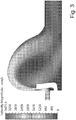
- a fourth annular wall portion 148 may be provided in order to further separate the outlet-side exit of the internal channel 140 from the structure of the illustrated male luer fitting. This feature strengthens the base of the male projection and, as shown in Fig. 3 , a fourth annular wall portion 148 would aid in ensuring a transition to laminar or laminar-like flow if the valve assembly 100 were to be used at higher flow rates.
- the fourth annular wall portion 148 should be considered an optional feature of the embodiments.
- Fig. 3 shows a simulated flow velocity field for fluid and cells passing through a valve assembly 100 of the exemplary first embodiment.
- the simulation is a two dimensional simulation of one half of the volume of the internal channel 140, but since most embodiments will be radially symmetric, the simulation is representative of the three dimensional flow field within such a device.
- flow paths through the internal channel 140 will tend to follow the curvature of the wall portions 142, 144, 146, with some flow across the lee side of the umbrella-type valve 170.
- Fig. 3 shows that there will be essentially one such region ⁇ where incoming fluid encounters and passes around the umbrella-type valve ⁇ in valve assemblies 100 like that of the first embodiment.
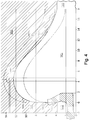
- Fig. 4 shows a cross-section of the exemplary second embodiment.
- the check valve assembly 100 includes a first annular wall portion 142 proximate the inlet port 120 and a second annular wall portion 144 having a both a first subportion 144a with a constant radius of curvature, following the r ' of equation (1), and a second subportion 144b with an increasing radius of curvature, deviating from the r' of equation (2a) but remaining within the genus of wall portion curvatures permitted by equation (3).
- r(x) should remain a smooth function of x so as to produce an essentially continuously curved surface in order to minimize fluid pressure changes, turbulence, and microscale shear forces along the interior wall surface.
- first sub portion 144a may be arcuately curved and deviate from the r' of equation (1), 200, within the range 210 permitted by equation (3) (illustrated by dashed lines bracketing line 200), just as the second annular wall portion 144 and second subportion 144b are shown to deviate from the r ' of equation (2b), 200, within the range 210.
- the check valve assembly 100 of course includes that second subportion, as well as a third annular wall portion 146 with a decreasing radius of curvature, deviating from the r ' of equation (2b) but in this instance converging back toward r' as the wall portion 146 approaches outlet port 130.
- Fig. 5 shows a cross-section of an exemplary third embodiment.
- Fig. 6 shows a simulated flow velocity field for fluid and cells passing through a valve assembly 100 of the exemplary third embodiment. Again, in contrast to Fig. 1 , where flows paths impinge upon the walls of the interior space and include several abrupt changes in direction, Fig. 6 shows that there will be essentially one such region ⁇ where incoming fluid encounters and passes around the umbrella-type valve ⁇ in valve assemblies 100 like that of the third embodiment.
- the inlet part 150 and outlet part 160 mate about a line of separation "S" dividing the internal channel 140 at its widest point.
- the line of separation falls between the first subportion 144a of the second annular wall portion 144 and the second subportion 144b of the portion 144, although there may be other embodiments where the second annular wall portion may be modeled or described via one or more other equations, or even provided with an arbitrary concave-curved profile, and thus not divided by a line of separation corresponding to anything other than a point of maximum width.
- At least part of the second annular wall portion 144 may be molded as a longitudinally-projecting flange 156 (shown in Figs. 2 and 4 ) extending from an cylindrical outer wall portion 157 of the inlet part 150.
- the outlet part 160 may then be provided with a socket 166 (shown in Figs.
Claims (18)
- Rückschlagventilanordnung, Folgendes umfassend:einen länglichen Ventilkörper (110), der einen Einlassstutzen (150), einen Auslassstutzen (160) und einen inneren Kanal (140), der zwischen dem Einlassstutzen und dem Auslassstutzen kommuniziert, aufweist, die jeweils im Allgemeinen an einer mittigen Längsachse (L) des Ventilkörpers ausgerichtet sind;wobei der Einlassstutzen ein Schirmrückschlagventil (170) umfasst, das am Eingang des inneren Kanals angeordnet und dazu ausgelegt ist, die Umkehrströmung vom inneren Kanal zum Einlassstutzen zu blockieren;wobei der innere Kanal durch einen ersten ringförmigen Wandabschnitt (142) definiert ist, der im Allgemeinen senkrecht zur mittigen Längsachse ausgerichtet ist und einen Ventilsitz für das Schirmrückschlagventil ausbildet;und dadurch gekennzeichnet, dass:der innere Kanal ferner durch einen zweiten ringförmigen Wandabschnitt (144) definiert ist,der in Bezug zum inneren Kanal entlang der mittigen Längsachse konkav ist, an den ersten ringförmigen Wandabschnitt angrenzt und zum Auslassstutzen hin verläuft; undder innere Kanal ferner durch einen dritten ringförmigen Wandabschnitt (146) definiert ist, der in Bezug zum inneren Kanal entlang der mittigen Längsachse konkav ist, an den zweiten ringförmigen Wandabschnitt angrenzt und zum Auslassstutzen hin verläuft;wobei zumindest der zweite und dritte ringförmige Wandabschnitt eine im Wesentlichen durchgehend gekrümmte, zusammenhängende Innenfläche in Bezug zur und entlang der mittigen Längsachse ausbilden.
- Rückschlagventilanordnung nach Anspruch 1, wobei der längliche Ventilkörper aus mindestens zwei Teilen besteht, wobei ein erster Teil den Einlassstutzen, das Schirmrückschlagventil, den ersten ringförmigen Wandabschnitt und einen einlassseitigen Teilabschnitt des zweiten ringförmigen Wandabschnitts umfasst und ein zweiter Teil einen auslassseitigen Teilabschnitt des zweiten ringförmigen Wandabschnitts, den dritten ringförmigen Wandabschnitt und den Auslassstutzen umfasst.
- Rückschlagventilanordnung nach Anspruch 2, wobei der einlassseitige Teilabschnitt des zweiten ringförmigen Wandabschnitts von einer unmittelbaren Schräge im Allgemeinen senkrecht zur Längsachse an der Verbindung des einlassseitigen Teilabschnitts zum ersten ringförmigen Wandabschnitt in eine unmittelbare Schräge parallel zur Längsachse an der Verbindung des einlassseitigen Teils zum auslassseitigen Teil übergeht.
- Rückschlagventilanordnung nach Anspruch 3, wobei der zweite Teil einen zylindrischen Innenwandabschnitt umfasst, der an den auslassseitigen Teilabschnitt des zweiten ringförmigen Wandabschnitts angrenzt, wobei der zylindrische Innenwandabschnitt einen zylindrischen Außenwandabschnitt des ersten Teils bei der Montage der Rückschlagventilanordnung aufnimmt und darin eingreift.
- Rückschlagventilanordnung nach Anspruch 4, wobei der erste Teil einen Steg umfasst, der an den zylindrischen Außenwandabschnitt des ersten Teils angrenzt, und der zweite Teil einen entgegengesetzten Steg umfasst, der an den zylindrischen Innenwandabschnitt des zweiten Teils angrenzt, wobei der zylindrische Innenwandabschnitt den zylindrischen Außenwandabschnitt des ersten Teils bei der Montage der Rückschlagventilanordnung aufnimmt und darin eingreift.
- Rückschlagventilanordnung nach Anspruch 5, wobei der Steg des ersten Teils und/oder der entgegengesetzte Steg des zweiten Teils eine ringförmige und in Längsrichtung gewandte Nut umfasst.
- Rückschlagventilanordnung nach Anspruch 6, wobei eine ringförmige Dichtung in der ringförmigen Nut angeordnet ist.
- Rückschlagventilanordnung nach Anspruch 4, wobei der zylindrische Außenwandabschnitt des ersten Teils und der zylindrische Innenwandabschnitt des zweiten Teils durch Ultraschallschweißen, Quellschweißen oder einen Klebstoff miteinander verbunden sind.
- Rückschlagventilanordnung nach Anspruch 2, ferner dadurch gekennzeichnet, dass:
der Abstand entlang der mittigen Längsachse vom Eingang zum inneren Kanal zum Auslassstutzen als x bezeichnet wird und der radiale Abstand einer Innenwand des inneren Kanals von der mittigen Längsachse als r bezeichnet wird, wobei r abhängig von x gemäß den folgenden Gleichungen variiert:Gleichung (1)r'= 8 + √(20,25 - (x-4,5)^2) für 0 < x < 4,5 und r' > 8 für den einlassseitigen Teilabschnitt des zweiten ringförmigen Wandabschnitts;Gleichung (2a) r' = 0,0068*x^3 - 0,2242*x^2 + 1,5392*x + 9,6571 für 4,5 < x < 10,99 für den auslassseitigen Teilabschnitt des zweiten ringförmigen Wandabschnitts;Gleichung (2b) r' = 0,0068*x^3 - 0,2242*x^2 + 1,5392*x + 9,6571 für 10,99 < x < 18,1 für den dritten ringförmigen Wandabschnitt undGleichung (3)r(x) = r'(x) ± 2,0 jeweils für den einlassseitigen und auslassseitigen Teilabschnitt des zweiten ringförmigen Wandabschnitts und des dritten ringförmigen Wandabschnitts; wobei der Abstand r eine im Wesentlichen durchgehend gekrümmte Innenfläche definiert. - Rückschlagventilanordnung nach Anspruch 9, wobei der zweite Teil einen zylindrischen Innenwandabschnitt umfasst, der an den auslassseitigen Teilabschnitt des zweiten ringförmigen Wandabschnitts angrenzt, wobei der zylindrische Innenwandabschnitt einen zylindrischen Außenwandabschnitt des ersten Teils bei der Montage der Rückschlagventilanordnung aufnimmt und darin eingreift.
- Rückschlagventilanordnung nach Anspruch 10, wobei der erste Teil eine Anschlussfläche umfasst, die an den zylindrischen Außenwandabschnitt des ersten Teils angrenzt, und der zweite Teil eine entgegengesetzte Anschlussfläche umfasst, die an den zylindrischen Innenwandabschnitt des zweiten Teils angrenzt, wobei der zylindrische Innenwandabschnitt den zylindrischen Außenwandabschnitt des ersten Teils bei der Montage der Rückschlagventilanordnung aufnimmt und darin eingreift.
- Rückschlagventilanordnung nach Anspruch 10, wobei der zylindrische Außenwandabschnitt des ersten Teils und der zylindrische Innenwandabschnitt des zweiten Teils durch Ultraschallschweißen, Quellschweißen oder einen Klebstoff miteinander verbunden sind.
- Rückschlagventilanordnung nach Anspruch 9, wobei der längliche Ventilkörper aus mindestens zwei Teilen besteht, wobei ein erster Teil den Einlassstutzen, das Schirmrückschlagventil und die Abschnitte der Innenwand auf der Einlassstutzenseite eines Punkts maximaler Breite des inneren Kanals umfasst und ein zweiter Teil diese Abschnitte der Innenwand auf einer Auslassstutzenseite des Punkts maximaler Breite und den Auslassstutzen umfasst.
- Rückschlagventilanordnung nach Anspruch 2, ferner dadurch gekennzeichnet, dass:
der Abstand entlang der mittigen Längsachse vom Eingang zum inneren Kanal zum Auslassstutzen als x bezeichnet wird und der radiale Abstand einer Innenwand des inneren Kanals von der mittigen Längsachse als r bezeichnet wird, wobei r abhängig von x gemäß den folgenden Gleichungen variiert:Gleichung (4)r'= 12,25 + √(7,5625 - (x-2,75)^2) für 0 < x < 2,75 und r' > 12,25 für den einlassseitigen Teilabschnitt des zweiten ringförmigen Wandabschnitts;Gleichung (5a) r' = 0,00003*x^5 - 0,002*x^4 + 0,0506*x^3 - 0,5724*x^2 + 2,1563*x + 12,456 für 2,75 < x < 6,823 für den auslassseitigen Teilabschnitt des zweiten ringförmigen Wandabschnitts;Gleichung 5(b) r' = 0,00003*x^5 - 0,002*x^4 + 0,0506*x^3 - 0,5724*x^2 + 2,1563*x + 12,456 für 6,823 < x < 18,1 für den dritten ringförmigen Wandabschnitt undGleichung (6)r(x) = r'(x) ± 2,0 jeweils für den einlassseitigen und auslassseitigen Teilabschnitt des zweiten ringförmigen Wandabschnitts und des dritten ringförmigen Wandabschnitts; wobei der Abstand r eine im Wesentlichen durchgehend gekrümmte Innenfläche definiert. - Rückschlagventilanordnung nach Anspruch 14, wobei der zweite Teil einen zylindrischen Innenwandabschnitt umfasst, der an den auslassseitigen Teilabschnitt des zweiten ringförmigen Wandabschnitts angrenzt, wobei der zylindrische Innenwandabschnitt einen zylindrischen Außenwandabschnitt des ersten Teils bei der Montage der Rückschlagventilanordnung aufnimmt und darin eingreift.
- Rückschlagventilanordnung nach Anspruch 15, wobei der erste Teil eine Anschlussfläche umfasst, die an den zylindrischen Außenwandabschnitt des ersten Teils angrenzt, und der zweite Teil eine entgegengesetzte Anschlussfläche umfasst, die an den zylindrischen Innenwandabschnitt des zweiten Teils angrenzt, wobei der zylindrische Innenwandabschnitt den zylindrischen Außenwandabschnitt des ersten Teils bei der Montage der Rückschlagventilanordnung aufnimmt und darin eingreift.
- Rückschlagventilanordnung nach Anspruch 15, wobei der zylindrische Außenwandabschnitt des ersten Teils und der zylindrische Innenwandabschnitt des zweiten Teils durch Ultraschallschweißen, Quellschweißen oder einen Klebstoff miteinander verbunden sind.
- Rückschlagventilanordnung nach Anspruch 14, wobei der längliche Ventilkörper aus mindestens zwei Teilen besteht, wobei ein erster Teil den Einlassstutzen, das Schirmrückschlagventil und die Abschnitte der Innenwand auf der Einlassstutzenseite eines Punkts maximaler Breite des inneren Kanals umfasst und ein zweiter Teil diese Abschnitte der Innenwand auf einer Auslassstutzenseite des Punkts maximaler Breite und den Auslassstutzen umfasst.
Applications Claiming Priority (2)
| Application Number | Priority Date | Filing Date | Title |
|---|---|---|---|
| US201562113951P | 2015-02-09 | 2015-02-09 | |
| PCT/US2016/017078 WO2016130505A1 (en) | 2015-02-09 | 2016-02-09 | Umbrella check valve with reduce hemolysis |
Publications (3)
| Publication Number | Publication Date |
|---|---|
| EP3256763A1 EP3256763A1 (de) | 2017-12-20 |
| EP3256763A4 EP3256763A4 (de) | 2019-01-02 |
| EP3256763B1 true EP3256763B1 (de) | 2021-12-01 |
Family
ID=56565326
Family Applications (1)
| Application Number | Title | Priority Date | Filing Date |
|---|---|---|---|
| EP16749682.7A Active EP3256763B1 (de) | 2015-02-09 | 2016-02-09 | Schirmrückschlagventil mit reduzierter hämolyse |
Country Status (5)
| Country | Link |
|---|---|
| US (1) | US10112038B2 (de) |
| EP (1) | EP3256763B1 (de) |
| DK (1) | DK3256763T3 (de) |
| ES (1) | ES2902060T3 (de) |
| WO (1) | WO2016130505A1 (de) |
Families Citing this family (2)
| Publication number | Priority date | Publication date | Assignee | Title |
|---|---|---|---|---|
| EP4004414A4 (de) * | 2019-07-24 | 2023-07-26 | Quest Medical, Inc. | Gefiltertes vakuumentlastungsventil |
| IL273241B (en) * | 2020-03-11 | 2020-08-31 | Brevel Ltd | sealing valve |
Family Cites Families (14)
| Publication number | Priority date | Publication date | Assignee | Title |
|---|---|---|---|---|
| DE1119068B (de) * | 1957-01-09 | 1961-12-07 | Klein Schanzlin & Becker Ag | Rueckschlagventil |
| US3134394A (en) * | 1962-05-29 | 1964-05-26 | Ohta Tsunetaro | Check valves |
| US4084606A (en) * | 1974-04-23 | 1978-04-18 | Baxter Travenol Laboratories, Inc. | Fluid transfer device |
| DE2904686A1 (de) * | 1979-02-08 | 1980-08-14 | Volkswagenwerk Ag | Oelgeschmierte vakuumpumpe mit einem im bereich ihrer ansaugoeffnung angeordneten oelabscheider |
| US6062248A (en) * | 1997-08-13 | 2000-05-16 | Boelkins; Wallace G. | Fluid flow-sensor and valve |
| ITTO20010404A1 (it) * | 2001-04-27 | 2002-10-27 | Pres Block Spa | Valvola di tipo perfezionato. |
| US7326187B2 (en) * | 2002-08-13 | 2008-02-05 | Jms Co., Ltd. | Fluid control device |
| US7243676B2 (en) | 2004-05-19 | 2007-07-17 | Vernay Laboratories, Inc. | Combination umbrella and inverted bi-directional valve |
| US7438090B2 (en) * | 2005-01-06 | 2008-10-21 | Dynamic Air Inc. | Booster valve |
| CA2517785C (en) * | 2005-09-01 | 2009-06-02 | Masco Canada Limited | Check valve |
| US8337446B2 (en) * | 2005-09-02 | 2012-12-25 | Pokorney James L | Prosthetic heart valve housing |
| WO2007083599A1 (ja) * | 2006-01-17 | 2007-07-26 | Jms Co., Ltd. | 通水制御装置及びそれを用いた医療用注入回路 |
| US20080142102A1 (en) * | 2006-12-18 | 2008-06-19 | Savard Raymond T | Check Valve and Pump for High Purity Fluid Handling Systems |
| US9179808B2 (en) * | 2012-08-30 | 2015-11-10 | Gojo Industries, Inc. | Horizontal pumps, refill units and foam dispensers |
-
2016
- 2016-02-09 EP EP16749682.7A patent/EP3256763B1/de active Active
- 2016-02-09 ES ES16749682T patent/ES2902060T3/es active Active
- 2016-02-09 DK DK16749682.7T patent/DK3256763T3/da active
- 2016-02-09 US US15/019,125 patent/US10112038B2/en active Active
- 2016-02-09 WO PCT/US2016/017078 patent/WO2016130505A1/en active Application Filing
Non-Patent Citations (1)
| Title |
|---|
| None * |
Also Published As
| Publication number | Publication date |
|---|---|
| US20160228689A1 (en) | 2016-08-11 |
| EP3256763A4 (de) | 2019-01-02 |
| WO2016130505A8 (en) | 2017-03-09 |
| WO2016130505A1 (en) | 2016-08-18 |
| ES2902060T3 (es) | 2022-03-24 |
| EP3256763A1 (de) | 2017-12-20 |
| DK3256763T3 (da) | 2022-01-10 |
| US10112038B2 (en) | 2018-10-30 |
Similar Documents
| Publication | Publication Date | Title |
|---|---|---|
| CN100569313C (zh) | Y三通连接器及制造其的方法 | |
| US9108034B2 (en) | Infusion check valve for medical devices | |
| EP3079739B1 (de) | Rückschlagventil | |
| CA2510065C (en) | Magnetic automatic stop valve | |
| US9435450B2 (en) | Pressure differential relief valve | |
| US10610678B2 (en) | Bi-directional, pressure-actuated medical valve with improved fluid flow control and method of using such | |
| JP2008173474A (ja) | 医用輸液ライン等用のワンウェイバルブ | |
| US9651161B2 (en) | Check valve, especially for medical applications | |
| EP3256763B1 (de) | Schirmrückschlagventil mit reduzierter hämolyse | |
| EP0886534B1 (de) | Weiblicher luerkonnektor | |
| KR102630666B1 (ko) | 폐쇄 멈춤 꼭지 | |
| TW201137266A (en) | Fluid coupling | |
| ES2829953T3 (es) | Dispositivo de control de flujo | |
| US20160273665A1 (en) | Relievable check valve for medical lines | |
| CN109069732A (zh) | 微流限流器组合件及其制造方法 | |
| US8894629B2 (en) | High flow catheter valve | |
| JP2021156406A (ja) | 逆止弁 | |
| JPS62159867A (ja) | 医用弁装置 |
Legal Events
| Date | Code | Title | Description |
|---|---|---|---|
| STAA | Information on the status of an ep patent application or granted ep patent |
Free format text: STATUS: THE INTERNATIONAL PUBLICATION HAS BEEN MADE |
|
| PUAI | Public reference made under article 153(3) epc to a published international application that has entered the european phase |
Free format text: ORIGINAL CODE: 0009012 |
|
| STAA | Information on the status of an ep patent application or granted ep patent |
Free format text: STATUS: REQUEST FOR EXAMINATION WAS MADE |
|
| 17P | Request for examination filed |
Effective date: 20170712 |
|
| AK | Designated contracting states |
Kind code of ref document: A1 Designated state(s): AL AT BE BG CH CY CZ DE DK EE ES FI FR GB GR HR HU IE IS IT LI LT LU LV MC MK MT NL NO PL PT RO RS SE SI SK SM TR |
|
| AX | Request for extension of the european patent |
Extension state: BA ME |
|
| DAV | Request for validation of the european patent (deleted) | ||
| DAX | Request for extension of the european patent (deleted) | ||
| REG | Reference to a national code |
Ref country code: DE Ref legal event code: R079 Ref document number: 602016066814 Country of ref document: DE Free format text: PREVIOUS MAIN CLASS: F16K0015140000 Ipc: A61M0039240000 |
|
| A4 | Supplementary search report drawn up and despatched |
Effective date: 20181205 |
|
| RIC1 | Information provided on ipc code assigned before grant |
Ipc: F16K 15/14 20060101ALI20181129BHEP Ipc: A61M 39/24 20060101AFI20181129BHEP |
|
| STAA | Information on the status of an ep patent application or granted ep patent |
Free format text: STATUS: EXAMINATION IS IN PROGRESS |
|
| 17Q | First examination report despatched |
Effective date: 20201001 |
|
| GRAP | Despatch of communication of intention to grant a patent |
Free format text: ORIGINAL CODE: EPIDOSNIGR1 |
|
| STAA | Information on the status of an ep patent application or granted ep patent |
Free format text: STATUS: GRANT OF PATENT IS INTENDED |
|
| INTG | Intention to grant announced |
Effective date: 20210701 |
|
| GRAS | Grant fee paid |
Free format text: ORIGINAL CODE: EPIDOSNIGR3 |
|
| GRAA | (expected) grant |
Free format text: ORIGINAL CODE: 0009210 |
|
| STAA | Information on the status of an ep patent application or granted ep patent |
Free format text: STATUS: THE PATENT HAS BEEN GRANTED |
|
| AK | Designated contracting states |
Kind code of ref document: B1 Designated state(s): AL AT BE BG CH CY CZ DE DK EE ES FI FR GB GR HR HU IE IS IT LI LT LU LV MC MK MT NL NO PL PT RO RS SE SI SK SM TR |
|
| REG | Reference to a national code |
Ref country code: GB Ref legal event code: FG4D |
|
| REG | Reference to a national code |
Ref country code: AT Ref legal event code: REF Ref document number: 1451188 Country of ref document: AT Kind code of ref document: T Effective date: 20211215 Ref country code: CH Ref legal event code: EP |
|
| REG | Reference to a national code |
Ref country code: IE Ref legal event code: FG4D |
|
| REG | Reference to a national code |
Ref country code: DE Ref legal event code: R096 Ref document number: 602016066814 Country of ref document: DE |
|
| REG | Reference to a national code |
Ref country code: DK Ref legal event code: T3 Effective date: 20220106 |
|
| REG | Reference to a national code |
Ref country code: NL Ref legal event code: FP |
|
| REG | Reference to a national code |
Ref country code: ES Ref legal event code: FG2A Ref document number: 2902060 Country of ref document: ES Kind code of ref document: T3 Effective date: 20220324 |
|
| REG | Reference to a national code |
Ref country code: LT Ref legal event code: MG9D |
|
| PG25 | Lapsed in a contracting state [announced via postgrant information from national office to epo] |
Ref country code: RS Free format text: LAPSE BECAUSE OF FAILURE TO SUBMIT A TRANSLATION OF THE DESCRIPTION OR TO PAY THE FEE WITHIN THE PRESCRIBED TIME-LIMIT Effective date: 20211201 Ref country code: LT Free format text: LAPSE BECAUSE OF FAILURE TO SUBMIT A TRANSLATION OF THE DESCRIPTION OR TO PAY THE FEE WITHIN THE PRESCRIBED TIME-LIMIT Effective date: 20211201 Ref country code: FI Free format text: LAPSE BECAUSE OF FAILURE TO SUBMIT A TRANSLATION OF THE DESCRIPTION OR TO PAY THE FEE WITHIN THE PRESCRIBED TIME-LIMIT Effective date: 20211201 Ref country code: BG Free format text: LAPSE BECAUSE OF FAILURE TO SUBMIT A TRANSLATION OF THE DESCRIPTION OR TO PAY THE FEE WITHIN THE PRESCRIBED TIME-LIMIT Effective date: 20220301 |
|
| PG25 | Lapsed in a contracting state [announced via postgrant information from national office to epo] |
Ref country code: SE Free format text: LAPSE BECAUSE OF FAILURE TO SUBMIT A TRANSLATION OF THE DESCRIPTION OR TO PAY THE FEE WITHIN THE PRESCRIBED TIME-LIMIT Effective date: 20211201 Ref country code: PL Free format text: LAPSE BECAUSE OF FAILURE TO SUBMIT A TRANSLATION OF THE DESCRIPTION OR TO PAY THE FEE WITHIN THE PRESCRIBED TIME-LIMIT Effective date: 20211201 Ref country code: NO Free format text: LAPSE BECAUSE OF FAILURE TO SUBMIT A TRANSLATION OF THE DESCRIPTION OR TO PAY THE FEE WITHIN THE PRESCRIBED TIME-LIMIT Effective date: 20220301 Ref country code: LV Free format text: LAPSE BECAUSE OF FAILURE TO SUBMIT A TRANSLATION OF THE DESCRIPTION OR TO PAY THE FEE WITHIN THE PRESCRIBED TIME-LIMIT Effective date: 20211201 Ref country code: HR Free format text: LAPSE BECAUSE OF FAILURE TO SUBMIT A TRANSLATION OF THE DESCRIPTION OR TO PAY THE FEE WITHIN THE PRESCRIBED TIME-LIMIT Effective date: 20211201 Ref country code: GR Free format text: LAPSE BECAUSE OF FAILURE TO SUBMIT A TRANSLATION OF THE DESCRIPTION OR TO PAY THE FEE WITHIN THE PRESCRIBED TIME-LIMIT Effective date: 20220302 |
|
| PG25 | Lapsed in a contracting state [announced via postgrant information from national office to epo] |
Ref country code: SM Free format text: LAPSE BECAUSE OF FAILURE TO SUBMIT A TRANSLATION OF THE DESCRIPTION OR TO PAY THE FEE WITHIN THE PRESCRIBED TIME-LIMIT Effective date: 20211201 Ref country code: SK Free format text: LAPSE BECAUSE OF FAILURE TO SUBMIT A TRANSLATION OF THE DESCRIPTION OR TO PAY THE FEE WITHIN THE PRESCRIBED TIME-LIMIT Effective date: 20211201 Ref country code: RO Free format text: LAPSE BECAUSE OF FAILURE TO SUBMIT A TRANSLATION OF THE DESCRIPTION OR TO PAY THE FEE WITHIN THE PRESCRIBED TIME-LIMIT Effective date: 20211201 Ref country code: PT Free format text: LAPSE BECAUSE OF FAILURE TO SUBMIT A TRANSLATION OF THE DESCRIPTION OR TO PAY THE FEE WITHIN THE PRESCRIBED TIME-LIMIT Effective date: 20220401 Ref country code: EE Free format text: LAPSE BECAUSE OF FAILURE TO SUBMIT A TRANSLATION OF THE DESCRIPTION OR TO PAY THE FEE WITHIN THE PRESCRIBED TIME-LIMIT Effective date: 20211201 Ref country code: CZ Free format text: LAPSE BECAUSE OF FAILURE TO SUBMIT A TRANSLATION OF THE DESCRIPTION OR TO PAY THE FEE WITHIN THE PRESCRIBED TIME-LIMIT Effective date: 20211201 |
|
| PGFP | Annual fee paid to national office [announced via postgrant information from national office to epo] |
Ref country code: IT Payment date: 20220331 Year of fee payment: 7 |
|
| REG | Reference to a national code |
Ref country code: DE Ref legal event code: R097 Ref document number: 602016066814 Country of ref document: DE |
|
| PG25 | Lapsed in a contracting state [announced via postgrant information from national office to epo] |
Ref country code: MC Free format text: LAPSE BECAUSE OF FAILURE TO SUBMIT A TRANSLATION OF THE DESCRIPTION OR TO PAY THE FEE WITHIN THE PRESCRIBED TIME-LIMIT Effective date: 20211201 Ref country code: IS Free format text: LAPSE BECAUSE OF FAILURE TO SUBMIT A TRANSLATION OF THE DESCRIPTION OR TO PAY THE FEE WITHIN THE PRESCRIBED TIME-LIMIT Effective date: 20220401 |
|
| PLBE | No opposition filed within time limit |
Free format text: ORIGINAL CODE: 0009261 |
|
| STAA | Information on the status of an ep patent application or granted ep patent |
Free format text: STATUS: NO OPPOSITION FILED WITHIN TIME LIMIT |
|
| REG | Reference to a national code |
Ref country code: BE Ref legal event code: MM Effective date: 20220228 |
|
| PG25 | Lapsed in a contracting state [announced via postgrant information from national office to epo] |
Ref country code: LU Free format text: LAPSE BECAUSE OF NON-PAYMENT OF DUE FEES Effective date: 20220209 Ref country code: AL Free format text: LAPSE BECAUSE OF FAILURE TO SUBMIT A TRANSLATION OF THE DESCRIPTION OR TO PAY THE FEE WITHIN THE PRESCRIBED TIME-LIMIT Effective date: 20211201 |
|
| 26N | No opposition filed |
Effective date: 20220902 |
|
| PG25 | Lapsed in a contracting state [announced via postgrant information from national office to epo] |
Ref country code: SI Free format text: LAPSE BECAUSE OF FAILURE TO SUBMIT A TRANSLATION OF THE DESCRIPTION OR TO PAY THE FEE WITHIN THE PRESCRIBED TIME-LIMIT Effective date: 20211201 |
|
| PG25 | Lapsed in a contracting state [announced via postgrant information from national office to epo] |
Ref country code: IE Free format text: LAPSE BECAUSE OF NON-PAYMENT OF DUE FEES Effective date: 20220209 |
|
| PG25 | Lapsed in a contracting state [announced via postgrant information from national office to epo] |
Ref country code: BE Free format text: LAPSE BECAUSE OF NON-PAYMENT OF DUE FEES Effective date: 20220228 |
|
| PGFP | Annual fee paid to national office [announced via postgrant information from national office to epo] |
Ref country code: FR Payment date: 20230221 Year of fee payment: 8 Ref country code: DK Payment date: 20230220 Year of fee payment: 8 Ref country code: CH Payment date: 20230307 Year of fee payment: 8 Ref country code: AT Payment date: 20230217 Year of fee payment: 8 |
|
| PG25 | Lapsed in a contracting state [announced via postgrant information from national office to epo] |
Ref country code: IT Free format text: LAPSE BECAUSE OF NON-PAYMENT OF DUE FEES Effective date: 20220209 |
|
| P01 | Opt-out of the competence of the unified patent court (upc) registered |
Effective date: 20230519 |
|
| PGFP | Annual fee paid to national office [announced via postgrant information from national office to epo] |
Ref country code: ES Payment date: 20230427 Year of fee payment: 8 |
|
| REG | Reference to a national code |
Ref country code: AT Ref legal event code: UEP Ref document number: 1451188 Country of ref document: AT Kind code of ref document: T Effective date: 20211201 |
|
| PG25 | Lapsed in a contracting state [announced via postgrant information from national office to epo] |
Ref country code: HU Free format text: LAPSE BECAUSE OF FAILURE TO SUBMIT A TRANSLATION OF THE DESCRIPTION OR TO PAY THE FEE WITHIN THE PRESCRIBED TIME-LIMIT; INVALID AB INITIO Effective date: 20160209 |
|
| PGFP | Annual fee paid to national office [announced via postgrant information from national office to epo] |
Ref country code: ES Payment date: 20240326 Year of fee payment: 9 Ref country code: NL Payment date: 20240219 Year of fee payment: 9 |
|
| PGFP | Annual fee paid to national office [announced via postgrant information from national office to epo] |
Ref country code: AT Payment date: 20240220 Year of fee payment: 9 |
|
| PG25 | Lapsed in a contracting state [announced via postgrant information from national office to epo] |
Ref country code: MK Free format text: LAPSE BECAUSE OF FAILURE TO SUBMIT A TRANSLATION OF THE DESCRIPTION OR TO PAY THE FEE WITHIN THE PRESCRIBED TIME-LIMIT Effective date: 20211201 Ref country code: CY Free format text: LAPSE BECAUSE OF FAILURE TO SUBMIT A TRANSLATION OF THE DESCRIPTION OR TO PAY THE FEE WITHIN THE PRESCRIBED TIME-LIMIT Effective date: 20211201 |
|
| PGFP | Annual fee paid to national office [announced via postgrant information from national office to epo] |
Ref country code: DE Payment date: 20240219 Year of fee payment: 9 Ref country code: GB Payment date: 20240219 Year of fee payment: 9 Ref country code: CH Payment date: 20240301 Year of fee payment: 9 |