EP3255358A1 - Heat exchange apparatus and semi-conductor cooling refrigerator provided with same - Google Patents
Heat exchange apparatus and semi-conductor cooling refrigerator provided with same Download PDFInfo
- Publication number
- EP3255358A1 EP3255358A1 EP15880936.8A EP15880936A EP3255358A1 EP 3255358 A1 EP3255358 A1 EP 3255358A1 EP 15880936 A EP15880936 A EP 15880936A EP 3255358 A1 EP3255358 A1 EP 3255358A1
- Authority
- EP
- European Patent Office
- Prior art keywords
- pipe
- heat
- exchanging apparatus
- heat exchanging
- segment
- Prior art date
- Legal status (The legal status is an assumption and is not a legal conclusion. Google has not performed a legal analysis and makes no representation as to the accuracy of the status listed.)
- Granted
Links
- 239000004065 semiconductor Substances 0.000 title claims abstract description 37
- 238000001816 cooling Methods 0.000 title claims abstract description 22
- 239000003570 air Substances 0.000 claims description 22
- 239000012080 ambient air Substances 0.000 claims description 6
- 239000007788 liquid Substances 0.000 description 7
- 238000001704 evaporation Methods 0.000 description 5
- 238000012986 modification Methods 0.000 description 2
- 230000004048 modification Effects 0.000 description 2
- 230000007547 defect Effects 0.000 description 1
- 230000000694 effects Effects 0.000 description 1
- 230000008020 evaporation Effects 0.000 description 1
- 239000004519 grease Substances 0.000 description 1
- 238000010438 heat treatment Methods 0.000 description 1
- 238000000034 method Methods 0.000 description 1
- 229920001296 polysiloxane Polymers 0.000 description 1
- 239000011148 porous material Substances 0.000 description 1
- 230000005855 radiation Effects 0.000 description 1
- 238000003466 welding Methods 0.000 description 1
Images


Classifications
-
- F—MECHANICAL ENGINEERING; LIGHTING; HEATING; WEAPONS; BLASTING
- F28—HEAT EXCHANGE IN GENERAL
- F28D—HEAT-EXCHANGE APPARATUS, NOT PROVIDED FOR IN ANOTHER SUBCLASS, IN WHICH THE HEAT-EXCHANGE MEDIA DO NOT COME INTO DIRECT CONTACT
- F28D15/00—Heat-exchange apparatus with the intermediate heat-transfer medium in closed tubes passing into or through the conduit walls ; Heat-exchange apparatus employing intermediate heat-transfer medium or bodies
- F28D15/02—Heat-exchange apparatus with the intermediate heat-transfer medium in closed tubes passing into or through the conduit walls ; Heat-exchange apparatus employing intermediate heat-transfer medium or bodies in which the medium condenses and evaporates, e.g. heat pipes
-
- H—ELECTRICITY
- H01—ELECTRIC ELEMENTS
- H01L—SEMICONDUCTOR DEVICES NOT COVERED BY CLASS H10
- H01L23/00—Details of semiconductor or other solid state devices
- H01L23/34—Arrangements for cooling, heating, ventilating or temperature compensation ; Temperature sensing arrangements
- H01L23/42—Fillings or auxiliary members in containers or encapsulations selected or arranged to facilitate heating or cooling
- H01L23/427—Cooling by change of state, e.g. use of heat pipes
-
- F—MECHANICAL ENGINEERING; LIGHTING; HEATING; WEAPONS; BLASTING
- F28—HEAT EXCHANGE IN GENERAL
- F28D—HEAT-EXCHANGE APPARATUS, NOT PROVIDED FOR IN ANOTHER SUBCLASS, IN WHICH THE HEAT-EXCHANGE MEDIA DO NOT COME INTO DIRECT CONTACT
- F28D15/00—Heat-exchange apparatus with the intermediate heat-transfer medium in closed tubes passing into or through the conduit walls ; Heat-exchange apparatus employing intermediate heat-transfer medium or bodies
- F28D15/02—Heat-exchange apparatus with the intermediate heat-transfer medium in closed tubes passing into or through the conduit walls ; Heat-exchange apparatus employing intermediate heat-transfer medium or bodies in which the medium condenses and evaporates, e.g. heat pipes
- F28D15/0233—Heat-exchange apparatus with the intermediate heat-transfer medium in closed tubes passing into or through the conduit walls ; Heat-exchange apparatus employing intermediate heat-transfer medium or bodies in which the medium condenses and evaporates, e.g. heat pipes the conduits having a particular shape, e.g. non-circular cross-section, annular
-
- F—MECHANICAL ENGINEERING; LIGHTING; HEATING; WEAPONS; BLASTING
- F25—REFRIGERATION OR COOLING; COMBINED HEATING AND REFRIGERATION SYSTEMS; HEAT PUMP SYSTEMS; MANUFACTURE OR STORAGE OF ICE; LIQUEFACTION SOLIDIFICATION OF GASES
- F25B—REFRIGERATION MACHINES, PLANTS OR SYSTEMS; COMBINED HEATING AND REFRIGERATION SYSTEMS; HEAT PUMP SYSTEMS
- F25B39/00—Evaporators; Condensers
-
- F—MECHANICAL ENGINEERING; LIGHTING; HEATING; WEAPONS; BLASTING
- F25—REFRIGERATION OR COOLING; COMBINED HEATING AND REFRIGERATION SYSTEMS; HEAT PUMP SYSTEMS; MANUFACTURE OR STORAGE OF ICE; LIQUEFACTION SOLIDIFICATION OF GASES
- F25D—REFRIGERATORS; COLD ROOMS; ICE-BOXES; COOLING OR FREEZING APPARATUS NOT OTHERWISE PROVIDED FOR
- F25D11/00—Self-contained movable devices, e.g. domestic refrigerators
-
- F—MECHANICAL ENGINEERING; LIGHTING; HEATING; WEAPONS; BLASTING
- F25—REFRIGERATION OR COOLING; COMBINED HEATING AND REFRIGERATION SYSTEMS; HEAT PUMP SYSTEMS; MANUFACTURE OR STORAGE OF ICE; LIQUEFACTION SOLIDIFICATION OF GASES
- F25D—REFRIGERATORS; COLD ROOMS; ICE-BOXES; COOLING OR FREEZING APPARATUS NOT OTHERWISE PROVIDED FOR
- F25D19/00—Arrangement or mounting of refrigeration units with respect to devices or objects to be refrigerated, e.g. infrared detectors
-
- F—MECHANICAL ENGINEERING; LIGHTING; HEATING; WEAPONS; BLASTING
- F28—HEAT EXCHANGE IN GENERAL
- F28D—HEAT-EXCHANGE APPARATUS, NOT PROVIDED FOR IN ANOTHER SUBCLASS, IN WHICH THE HEAT-EXCHANGE MEDIA DO NOT COME INTO DIRECT CONTACT
- F28D15/00—Heat-exchange apparatus with the intermediate heat-transfer medium in closed tubes passing into or through the conduit walls ; Heat-exchange apparatus employing intermediate heat-transfer medium or bodies
- F28D15/02—Heat-exchange apparatus with the intermediate heat-transfer medium in closed tubes passing into or through the conduit walls ; Heat-exchange apparatus employing intermediate heat-transfer medium or bodies in which the medium condenses and evaporates, e.g. heat pipes
- F28D15/0266—Heat-exchange apparatus with the intermediate heat-transfer medium in closed tubes passing into or through the conduit walls ; Heat-exchange apparatus employing intermediate heat-transfer medium or bodies in which the medium condenses and evaporates, e.g. heat pipes with separate evaporating and condensing chambers connected by at least one conduit; Loop-type heat pipes; with multiple or common evaporating or condensing chambers
-
- F—MECHANICAL ENGINEERING; LIGHTING; HEATING; WEAPONS; BLASTING
- F28—HEAT EXCHANGE IN GENERAL
- F28D—HEAT-EXCHANGE APPARATUS, NOT PROVIDED FOR IN ANOTHER SUBCLASS, IN WHICH THE HEAT-EXCHANGE MEDIA DO NOT COME INTO DIRECT CONTACT
- F28D15/00—Heat-exchange apparatus with the intermediate heat-transfer medium in closed tubes passing into or through the conduit walls ; Heat-exchange apparatus employing intermediate heat-transfer medium or bodies
- F28D15/02—Heat-exchange apparatus with the intermediate heat-transfer medium in closed tubes passing into or through the conduit walls ; Heat-exchange apparatus employing intermediate heat-transfer medium or bodies in which the medium condenses and evaporates, e.g. heat pipes
- F28D15/0275—Arrangements for coupling heat-pipes together or with other structures, e.g. with base blocks; Heat pipe cores
-
- F—MECHANICAL ENGINEERING; LIGHTING; HEATING; WEAPONS; BLASTING
- F28—HEAT EXCHANGE IN GENERAL
- F28D—HEAT-EXCHANGE APPARATUS, NOT PROVIDED FOR IN ANOTHER SUBCLASS, IN WHICH THE HEAT-EXCHANGE MEDIA DO NOT COME INTO DIRECT CONTACT
- F28D15/00—Heat-exchange apparatus with the intermediate heat-transfer medium in closed tubes passing into or through the conduit walls ; Heat-exchange apparatus employing intermediate heat-transfer medium or bodies
- F28D15/02—Heat-exchange apparatus with the intermediate heat-transfer medium in closed tubes passing into or through the conduit walls ; Heat-exchange apparatus employing intermediate heat-transfer medium or bodies in which the medium condenses and evaporates, e.g. heat pipes
- F28D15/04—Heat-exchange apparatus with the intermediate heat-transfer medium in closed tubes passing into or through the conduit walls ; Heat-exchange apparatus employing intermediate heat-transfer medium or bodies in which the medium condenses and evaporates, e.g. heat pipes with tubes having a capillary structure
- F28D15/046—Heat-exchange apparatus with the intermediate heat-transfer medium in closed tubes passing into or through the conduit walls ; Heat-exchange apparatus employing intermediate heat-transfer medium or bodies in which the medium condenses and evaporates, e.g. heat pipes with tubes having a capillary structure characterised by the material or the construction of the capillary structure
-
- H—ELECTRICITY
- H01—ELECTRIC ELEMENTS
- H01L—SEMICONDUCTOR DEVICES NOT COVERED BY CLASS H10
- H01L23/00—Details of semiconductor or other solid state devices
- H01L23/34—Arrangements for cooling, heating, ventilating or temperature compensation ; Temperature sensing arrangements
- H01L23/36—Selection of materials, or shaping, to facilitate cooling or heating, e.g. heatsinks
- H01L23/367—Cooling facilitated by shape of device
- H01L23/3672—Foil-like cooling fins or heat sinks
-
- H—ELECTRICITY
- H01—ELECTRIC ELEMENTS
- H01L—SEMICONDUCTOR DEVICES NOT COVERED BY CLASS H10
- H01L23/00—Details of semiconductor or other solid state devices
- H01L23/34—Arrangements for cooling, heating, ventilating or temperature compensation ; Temperature sensing arrangements
- H01L23/46—Arrangements for cooling, heating, ventilating or temperature compensation ; Temperature sensing arrangements involving the transfer of heat by flowing fluids
- H01L23/473—Arrangements for cooling, heating, ventilating or temperature compensation ; Temperature sensing arrangements involving the transfer of heat by flowing fluids by flowing liquids
-
- F—MECHANICAL ENGINEERING; LIGHTING; HEATING; WEAPONS; BLASTING
- F28—HEAT EXCHANGE IN GENERAL
- F28F—DETAILS OF HEAT-EXCHANGE AND HEAT-TRANSFER APPARATUS, OF GENERAL APPLICATION
- F28F2215/00—Fins
-
- F—MECHANICAL ENGINEERING; LIGHTING; HEATING; WEAPONS; BLASTING
- F28—HEAT EXCHANGE IN GENERAL
- F28F—DETAILS OF HEAT-EXCHANGE AND HEAT-TRANSFER APPARATUS, OF GENERAL APPLICATION
- F28F2255/00—Heat exchanger elements made of materials having special features or resulting from particular manufacturing processes
- F28F2255/18—Heat exchanger elements made of materials having special features or resulting from particular manufacturing processes sintered
Landscapes
- Engineering & Computer Science (AREA)
- Physics & Mathematics (AREA)
- Thermal Sciences (AREA)
- Mechanical Engineering (AREA)
- General Engineering & Computer Science (AREA)
- Life Sciences & Earth Sciences (AREA)
- Sustainable Development (AREA)
- Chemical & Material Sciences (AREA)
- Combustion & Propulsion (AREA)
- Condensed Matter Physics & Semiconductors (AREA)
- General Physics & Mathematics (AREA)
- Computer Hardware Design (AREA)
- Microelectronics & Electronic Packaging (AREA)
- Power Engineering (AREA)
- Materials Engineering (AREA)
- Cooling Or The Like Of Semiconductors Or Solid State Devices (AREA)
- Heat-Exchange Devices With Radiators And Conduit Assemblies (AREA)
Abstract
Description
- The present application claims the priority of the Chinese patent application No.
201510056281.7 filed on February 3, 2015 - The present invention is related to a heat exchanging apparatus, and more particularly to a heat exchanging apparatus having a sintered heat pipe and a semiconductor refrigerator having the heat exchanging apparatus.
- A sintered heat pipe works in the principle that evaporation is utilized to cool a sintered heat pipe so that the temperature difference at the two ends of the heat pipe is quite large to quickly transfer heat. Thanks to their excellent heat transfer performance and other technical advantages, sintered heat pipes are widely used in the field of heat radiation. An existing sintered heat pipe extends from its one end to the other along an exclusive path, which may be linear, L-shaped or U-shaped. One end of the existing sintered heat pipe is an evaporating segment (or a heating segment), and the other end thereof is a condensing segment (or a cooling segment), and a heat insulating segment may be arranged between the evaporating and condensing segments according to the application needs. When one end of the sintered heat pipe is heated, the liquid in the capillary core is evaporated and vaporized. The vapors flow to the other end due to a slight pressure difference, emits heat and condenses into liquid again. Then, the liquid flows to the evaporating segment again under the capillary force along porous materials. This process cycles endlessly, transferring the heat from one end to the other end of the sintered heat pipe. Usually, a heat exchanging apparatus having such a sintered heat pipe is provided with fins on the condensing segment or the evaporating segment of the sintered heat pipe for radiating heat or transferring cold. However, existing heat exchanging apparatuses may not achieve desired effects when radiating heat for heat sources of a high heat flow density such as semiconductor cooling plates.
- One object of a first aspect of the present invention is to overcome at least one defect of an existing heat exchanging apparatus by providing a novel heat exchanging apparatus.
- A further object of the first aspect of the present invention is to improve the heat radiating or cold transferring efficiency of the heat exchanging apparatus so as to adapt to a heat or cold source of a high heat flow density.
- One object of a second aspect of the present invention is to provide a semiconductor refrigerator having the heat exchanging apparatus.
- The first aspect of the present invention provides a heat exchanging apparatus comprising one or more sintered heat pipes. In particular, each sintered heat pipe comprises a main pipe with both ends closed and having a first pipe segment and a second pipe segment, wherein the first pipe segment is configured to connect a heat or cold source, and one or more manifolds for radiating heat or transferring cold extend from one or more portions of the second pipe segment of the main pipe respectively.
- Optionally, the first pipe segment of the main pipe is formed by extending from one end of the main pipe to the other end thereof by a predetermined length, and the second pipe segment of the main pipe is formed by extending from the other end of the main pipe to the one end thereof by a predetermined length.
- Optionally, the first pipe segment of the main pipe is a straight pipe, and the first pipe segments of multiple main pipes are located in the same plane in parallel and with gaps therebetween.
- Optionally, the heat exchanging apparatus further comprises: a fixed bottom plate whose one surface is provided with one or more grooves, and a fixed cover plate whose one surface is provided with one or more grooves and which is configured to cooperate with the fixed bottom plate to clamp the first pipe segment of the main pipe between the grooves of the fixed cover plate and of the fixed bottom plate.
- Optionally, the second pipe segment of the main pipe is a straight pipe, and the second pipe segments of the multiple main pipes are located in the same plane in parallel and with gaps therebetween.
- Optionally, the second pipe segment of the main pipe comprises a first straight pipe portion whose one end communicates with the corresponding first pipe segment, and a second straight pipe portion which extends from the other end of the first straight pipe portion perpendicularly relative to the first straight pipe portion and whose tail end is closed, wherein the first straight pipe portions of the second pipe segments of the multiple main pipes are located in the same plane in parallel and with gaps therebetween, and a starting end of a manifold of each sintered heat pipe is located at the first straight pipe portion of the corresponding second pipe segment.
- Optionally, the projection of the manifold of each sintered heat pipe in a plane perpendicular to the corresponding first straight pipe portion overlaps with the projection of the corresponding second straight pipe portion in the plane.
- Optionally, the manifolds of each sintered heat pipe are located at the same side of the corresponding main pipe, or the manifolds of each sintered heat pipe are located at the opposite sides of the corresponding main pipe respectively.
- Optionally, the heat exchanging apparatus further comprises one or two fin groups, each fin group comprising multiple corresponding fins which are arranged in parallel and with gaps therebetween, and each fin group being installed at the manifold on a corresponding side of the main pipe via the pipe holes of the respective fins.
- Optionally, the heat exchanging apparatus further comprises a blower arranged at the same side as the multiple manifolds and configured such that an air inlet area of the blower sucks air flow and the air flow is blown to a gap between each two adjacent fins, or the air flow is sucked from the gap between each two adjacent fins and is then blown to the air inlet area.
- Optionally, the middle portion of each fin is provided with a receiving through hole so that each fin group defines a receiving space extending along the axes of the receiving through holes; the heat exchanging apparatus further comprises one or two blowers respectively provided in the receiving spaces of the corresponding fin groups and configured such that air flow is sucked from an air inlet area of each blower and is blown to a gap between each two adjacent fins of the corresponding fin group.
- The second aspect of the present invention provides a semiconductor refrigerator comprising an inner tank, a semiconductor cooling plate and a heat exchanging apparatus, wherein the heat exchanging apparatus is configured to radiate heat from a hot end of the semiconductor cooling plate to ambient air or to transfer cold from a cold end of the semiconductor cooling plate to a storage compartment of the inner tank. In particular, the heat exchanging apparatus is any of the above heat exchanging apparatuses; the first pipe segment of the main pipe of each sintered heat pipe of the heat exchanging apparatus is connected to the hot or cold end of the semiconductor cooling plate; and the manifold of each sintered heat pipe is configured to radiate heat to ambient air or transfer cold to the storage compartment.
- In the heat exchanging apparatus and the semiconductor refrigerator having the heat exchanging apparatus of the present invention, as multiple manifolds for radiating heat or transferring cold extend from the second pipe segment, the heat radiating or cold transferring efficiency of the heat exchanging apparatus and the semiconductor refrigerator is considerably improved, enabling the heat exchanging apparatus to adapt to heat/cold sources of a high heat flow density, such as semiconductor cooling plates, for radiating heat or transferring cold.
- Further, thanks to the special structure of each sintered heat pipe in the heat exchanging apparatus and the semiconductor refrigerator having the heat exchanging apparatus of the present invention, the structure of the heat exchanging apparatus is made compact.
- The above and other objects, advantages and features of the present invention will be understood by those skilled in the art more clearly with reference to the detailed description of the embodiments of the present below with reference to the accompanied drawings.
- The followings will describe some embodiments of the present in detail in an exemplary rather than restrictive manner with reference to the accompanying drawings. The same reference signs in the drawings represent the same or similar parts. Those skilled in the art shall understand that these drawings are only schematic ones of this invention, and may not be necessarily drawn according to the scales. In the drawings:
-
Fig. 1 is a schematic front view of a heat exchanging apparatus according to an embodiment of the present invention; -
Fig. 2 is a schematic left view of a heat exchanging apparatus according to an embodiment of the present invention; -
Fig. 3 is a schematic front view of a heat exchanging apparatus according to an embodiment of the present invention; -
Fig. 4 is a schematic front view of a heat exchanging apparatus according to the another embodiment of the present invention; -
Fig. 5 is a schematic front view of a heat exchanging apparatus according to another embodiment of the present invention; -
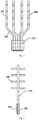
Fig. 6 is a schematic view of a sintered heat pipe of a heat exchanging apparatus according to an embodiment of the present invention; -
Fig. 7 is a schematic right view of a semiconductor refrigerator according to an embodiment of the present invention; and -
Fig. 8 is a schematic rear view of a semiconductor refrigerator according to an embodiment of the present invention. - Reference signs: 100-inner tank; 150-semiconductor cooling plate; 200-sintered heat pipe; 210-main pipe; 211-first pipe segment; 212-second pipe segment; 213-connecting pipe segment; 220-manifold; 310-fixed bottom plate; 320-fin group; 400-fin group; 410-fin; 500-blower; 2121-first straight pipe portion; 2122-second straight pipe portion.
-
Fig. 1 is a schematic front view of a heat exchanging apparatus according to an embodiment of the present invention. As shown inFigs. 1-2 , an embodiment of the present invention provides a heat exchanging apparatus, which is particularly suitable for radiating heat or transferring cold for a heat or cold source of a high heat flow density such as asemiconductor cooling plate 150, and may be applied in a semiconductor refrigerator. The heat exchanging apparatus may comprise one or more sinteredheat pipes 200 to sufficiently utilize the heat conduction performance of the sinteredheat pipes 200. In particular, each sinteredheat pipe 200 comprises amain pipe 210 with both ends closed and having afirst pipe segment 211 and asecond pipe segment 212, wherein thefirst pipe segment 211 is configured to connect the heat or cold source. Preferably, one ormore manifolds 220 for radiating heat or transferring cold extend from one or more portions of thesecond pipe segment 212 of themain pipe 210 respectively to improve the heat radiating or cold transferring efficiency of the heat exchanging apparatus. - In some embodiments of the present invention, the working chamber of the
manifold 220 may communicate with the working chamber of the correspondingmain pipe 210 to facilitate steam flow in the sinteredheat pipe 200. The liquid absorbing core in themanifold 220 may be connected with the liquid absorbing core in themain pipe 210. The liquid absorbing cores in themanifold 220 and in themain pipe 210 closely contact the inner wall of the corresponding pipes respectively to facilitate flow of the working liquid. Further, the diameter of themanifold 220 may equal that of themain pipe 210. In some alternative embodiments of the present invention, the diameter of themanifold 220 may be smaller than that of themain pipe 210. - In some preferred embodiments of the present invention, As shown in
Fig. 1 , thefirst pipe segment 211 of themain pipe 210 is formed by extending from one end of themain pipe 210 to the other end thereof by a predetermined length, and thesecond pipe segment 212 of themain pipe 210 is formed by extending from the other end of themain pipe 210 to the one end thereof by a predetermined length. - For example, the
first pipe segment 211 of themain pipe 210 may be a straight pipe, and thefirst pipe segments 211 of multiplemain pipes 210 are located in the same plane in parallel and with gaps therebetween. Thesecond pipe segment 212 of themain pipe 210 may be a straight pipe, and thesecond pipe segments 212 of multiplemain pipes 210 are located in the same plane in parallel and with gaps therebetween. The first andsecond pipe segments main pipe 210 may be arranged to be parallel, and themain pipe 210 may include aconnecting pipe segment 213 connected between the first andsecond pipe segments second pipe segments heat pipes 200. Themain pipes 210 of the four sinteredheat pipes 200 are arranged in the same plane in symmetry with respect to a geometrical symmetry plane. The length of the connectingpipe segment 213 of onesintered heat pipe 200 at one side of the geometrical symmetry plane is smaller than that of the connectingpipe segment 213 of the othersintered heat pipe 200 at the same side of the geometrical symmetry plane, so that the four sinteredheat pipes 200 are reasonably arranged. - To facilitate heat connection between the
sintered heat pipe 200 and the heat source and the cold source and the fixing of thesintered heat pipe 200, the heat exchanging apparatus of the embodiments of the present invention further comprises a fixedbottom plate 310 and a fixedcover plate 320. One surface of the fixedbottom plate 310 is provided with one or more grooves, and the other surface thereof may press the hot end or cold end of thesemiconductor cooling plate 150. In other words, thefirst pipe segment 211 of thesintered heat pipe 200 may be connected to the heat or cold source via the fixedbottom plate 310. One surface of the fixedcover plate 320 is also provided with one or more grooves, and the fixedcover plate 320 is configured to cooperate with the fixedbottom plate 310 to clamp thefirst pipe segment 211 of themain pipe 210 between the grooves of the fixedcover plate 320 and of the fixedbottom plate 310. After clamping thesintered heat pipe 200 between the fixedcover plate 320 and the fixedbottom plate 310, the three members are firmly fixed together by welding or mechanical squeezing. To effectively transfer heat, usually heat conducting silicone grease is coated on the contact surfaces between thesintered heat pipe 200 and the fixedbottom plate 310/the fixedcover plate 320. - In some embodiments of the present invention, the
manifolds 220 of eachsintered heat pipe 200 are located at the opposite sides of the correspondingmain pipe 210 respectively. There are at least threemanifolds 220 at each side of themain pipe 210. The starting ends of themanifolds 220 at each side of themain pipe 210 are arranged with equal gaps respectively along the extending direction of themain pipe 210. The numbers of themanifolds 220 at two sides of themain pipe 210 are the same. Each manifold at one side of themain pipe 220 is one the same line as thecorresponding manifold 220 at the other side of themain pipe 210. As well-known by those skilled in the art, themanifolds 220 at one side of themain pipe 210 are arranged with gaps relative to themanifolds 220 at the other side of themain pipe 210. In some preferred embodiments of the present invention, themanifolds 220 of eachsintered heat pipe 200 are located at the same side of the correspondingmain pipe 210. Each manifold 220 extends outwards from a corresponding part of the correspondingmain pipe 210 perpendicularly to a corresponding direction. -
Fig. 3 is a schematic front view of a heat exchanging apparatus according to an embodiment of the present invention. The heat exchanging apparatus in the present embodiment of the present invention may comprise one ormore fin groups 400, eachfin group 400 comprising multiplecorresponding fins 410 which are arranged in parallel and with gaps therebetween, and each fin group being installed at the manifold 220 on a corresponding side of themain pipe 210 via the pipe holes of therespective fins 410 to increase the heat radiating or cold transferring area. The heat exchanging apparatus may further comprise ablower 500 arranged at the same side as themultiple manifolds 220. For example, when thefins 410 are vertically arranged, theblower 500 may be arranged above the fin groups 400. Theblower 400 may be configured such that an air inlet area of the blower sucks air flow and the air flow is blown to a gap between each twoadjacent fins 410, or the air flow is sucked from the gap between each twoadjacent fins 410 and is then blown to the air inlet area. Specifically, theblower 500 may be anaxial flow blower 500 fixed on the fin groups 400. The rotary axis of the blades is perpendicular to each manifold 220. -
Fig. 4 is a schematic front view of a heat exchanging apparatus according to the another embodiment of the present invention. As shown inFigs. 4-6 , thefirst pipe segment 211 of themain pipe 210 is a straight pipe, and thefirst pipe segments 211 of multiplemain pipes 210 are located in the same plane in parallel and with gaps therebetween. Thesecond pipe segment 212 of themain pipe 210 comprises a firststraight pipe portion 2121 whose one end communicates with the correspondingfirst pipe segment 211, and a secondstraight pipe portion 2122 which extends from the other end of the firststraight pipe portion 2121 perpendicularly relative to the firststraight pipe portion 2121 and whose tail end is closed. The firststraight pipe portions 2121 of thesecond pipe segments 212 of multiplemain pipes 210 are located in the same plane in parallel and with gaps therebetween. The starting end of amanifold 220 of eachsintered heat pipe 200 is located at the firststraight pipe portion 2121 of the correspondingsecond pipe segment 212. The projection of themanifold 220 of eachsintered heat pipe 200 in a plane perpendicular to the corresponding firststraight pipe portion 2121 overlaps with the projection of the corresponding secondstraight pipe portion 2122 in the plane. - The heat exchanging apparatus may further comprise
multiple fins 410 andmultiple blowers 500. Themultiple fins 410 are arranged in parallel and with gaps therebetween to form afin group 400. The middle portion of eachfin 410 is provided with a receiving through hole so that eachfin group 400 defines a receiving space extending along the axes of the receiving through holes. The multiple blowers are respectively provided in the receiving spaces and configured such that air flow is sucked from an air inlet area of each blower and is blown to a gap between each twoadjacent fins 410 of thecorresponding fin group 400. Theblower 500 is a centrifugal blower. The rotary axis of the blades overlaps with the axis of the receiving through hole, so that air flow is sucked from an axial direction of the centrifugal blower and is blown to the gap between each twoadjacent fins 410 using a centrifugal force. Thefin 410 is a plate whose middle part is provided with the receiving through hole and whose outer profile is rectangular. Thefin group 400 may be installed on the secondstraight pipe portions 2122 of the main pipe via the pipe holes of therespective fins 410, respectively. -
Fig. 7 is a schematic right view of a semiconductor refrigerator according to an embodiment of the present invention. As shown inFigs. 7-8 , the present invention further provides a semiconductor refrigerator, comprising aninner tank 100, asemiconductor cooling plate 150 and a heat exchanging apparatus. The heat exchanging apparatus is configured to radiate heat from a hot end of thesemiconductor cooling plate 150 to ambient air or to transfer cold from a cold end of thesemiconductor cooling plate 150 to a storage compartment of theinner tank 100. In particular, the heat exchanging apparatus is the heat exchanging apparatus of any of the above embodiments. Thefirst pipe segment 211 of themain pipe 210 of eachsintered heat pipe 200 of the heat exchanging apparatus is connected to the hot or cold end of thesemiconductor cooling plate 150. Themanifold 220 of eachsintered heat pipe 200 is configured to radiate heat to ambient air or transfer cold to the storage compartment. When the heat exchanging apparatus is a hot end heat exchanging apparatus, thefirst pipe segment 211 of themain pipe 210 of eachsintered heat pipe 200 of the heat exchanging apparatus is connected to the hot end of thesemiconductor cooling plate 150, and thesecond pipe segment 212 of themain pipe 210 of eachsintered heat pipe 200 may be located above thefirst pipe segment 211. When the heat exchanging apparatus is a cold end heat exchanging apparatus, thefirst pipe segment 211 of themain pipe 210 of eachsintered heat pipe 200 of the heat exchanging apparatus is connected to the cold end of thesemiconductor cooling plate 150, and thesecond pipe segment 212 of themain pipe 210 of eachsintered heat pipe 200 may be located below thefirst pipe segment 211. - Although multiple embodiments of this invention have been illustrated and described in detail, those skilled in the art may make various modifications and variations to the present invention based on the content disclosed by the present invention or the content derived therefrom without departing from the spirit and scope of the present invention. Thus, the scope of the present invention should be understood and deemed to include these and other modifications and variations.
Claims (12)
- A heat exchanging apparatus, comprising one or more sintered heat pipes, and being characterized in that:each sintered heat pipe comprises a main pipe with both ends closed and having a first pipe segment and a second pipe segment, wherein the first pipe segment is configured to connect a heat or cold source, andone or more manifolds for radiating heat or transferring cold extend from one or more portions of the second pipe segment of the main pipe respectively.
- The heat exchanging apparatus of claim 1, being characterized in that:the first pipe segment of the main pipe is formed by extending from one end of the main pipe to the other end thereof by a predetermined length, andthe second pipe segment of the main pipe is formed by extending from the other end of the main pipe to the one end thereof by a predetermined length.
- The heat exchanging apparatus of claim 1, being characterized in that: the first pipe segment of the main pipe is a straight pipe, and the first pipe segments of multiple main pipes are located in the same plane in parallel and with gaps therebetween.
- The heat exchanging apparatus of claim 1, being characterized by further comprising:a fixed bottom plate whose one surface is provided with one or more grooves, anda fixed cover plate whose one surface is provided with one or more grooves and which is configured to cooperate with the fixed bottom plate to clamp the first pipe segment of the main pipe between the grooves of the fixed cover plate and of the fixed bottom plate.
- The heat exchanging apparatus of claim 1, being characterized in that: the second pipe segment of the main pipe is a straight pipe, and the second pipe segments of the multiple main pipes are located in the same plane in parallel and with gaps therebetween.
- The heat exchanging apparatus of claim 1, being characterized in that: the second pipe segment of the main pipe comprises a first straight pipe portion whose one end communicates with the corresponding first pipe segment, and a second straight pipe portion which extends from the other end of the first straight pipe portion perpendicularly relative to the first straight pipe portion and whose tail end is closed, wherein the first straight pipe portions of the second pipe segments of the multiple main pipes are located in the same plane in parallel and with gaps therebetween, and a starting end of a manifold of each sintered heat pipe is located at the first straight pipe portion of the corresponding second pipe segment.
- The heat exchanging apparatus of claim 6, being characterized in that: the projection of the manifold of each sintered heat pipe in a plane perpendicular to the corresponding first straight pipe portion overlaps with the projection of the corresponding second straight pipe portion in the plane.
- The heat exchanging apparatus of claim 1, being characterized in that: the manifolds of each sintered heat pipe are located at the same side of the corresponding main pipe, or the manifolds of each sintered heat pipe are located at the opposite sides of the corresponding main pipe respectively.
- The heat exchanging apparatus of claim 8, being characterized by further comprising: one or two fin groups, each fin group comprising multiple corresponding fins which are arranged in parallel and with gaps therebetween, and each fin group being installed at the manifold on a corresponding side of the main pipe via the pipe holes of the respective fins.
- The heat exchanging apparatus of claim 9, being characterized by further comprising: a blower arranged at the same side as the multiple manifolds and configured such that an air inlet area of the blower sucks air flow and the air flow is blown to a gap between each two adjacent fins, or the air flow is sucked from the gap between each two adjacent fins and is then blown to the air inlet area.
- The heat exchanging apparatus of claim 9, being characterized in that: the middle portion of each fin is provided with a receiving through hole so that each fin group defines a receiving space extending along the axes of the receiving through holes; and
the heat exchanging apparatus further comprises one or two blowers respectively provided in the receiving spaces of the corresponding fin groups and configured such that air flow is sucked from an air inlet area of each blower and is blown to a gap between each two adjacent fins of the corresponding fin group. - A semiconductor refrigerator comprising an inner tank, a semiconductor cooling plate and a heat exchanging apparatus, wherein the heat exchanging apparatus is configured to radiate heat from a hot end of the semiconductor cooling plate to ambient air or to transfer cold from a cold end of the semiconductor cooling plate to a storage compartment of the inner tank, the semiconductor refrigerator being characterized in that:the heat exchanging apparatus is the heat exchanging apparatus according to any of claims 1-11;the first pipe segment of the main pipe of each sintered heat pipe of the heat exchanging apparatus is connected to the hot or cold end of the semiconductor cooling plate; andthe manifold of each sintered heat pipe is configured to radiate heat to ambient air or transfer cold to the storage compartment.
Applications Claiming Priority (2)
| Application Number | Priority Date | Filing Date | Title |
|---|---|---|---|
| CN201510056281.7A CN104654670B (en) | 2015-02-03 | 2015-02-03 | Heat-exchanger rig and there is its semiconductor freezer |
| PCT/CN2015/091093 WO2016123994A1 (en) | 2015-02-03 | 2015-09-29 | Heat exchange apparatus and semi-conductor cooling refrigerator provided with same |
Publications (3)
| Publication Number | Publication Date |
|---|---|
| EP3255358A1 true EP3255358A1 (en) | 2017-12-13 |
| EP3255358A4 EP3255358A4 (en) | 2018-09-12 |
| EP3255358B1 EP3255358B1 (en) | 2020-08-26 |
Family
ID=53246092
Family Applications (1)
| Application Number | Title | Priority Date | Filing Date |
|---|---|---|---|
| EP15880936.8A Active EP3255358B1 (en) | 2015-02-03 | 2015-09-29 | Heat exchange apparatus and semi-conductor cooling refrigerator provided with same |
Country Status (4)
| Country | Link |
|---|---|
| US (1) | US20170330819A1 (en) |
| EP (1) | EP3255358B1 (en) |
| CN (1) | CN104654670B (en) |
| WO (1) | WO2016123994A1 (en) |
Cited By (1)
| Publication number | Priority date | Publication date | Assignee | Title |
|---|---|---|---|---|
| EP3896378A1 (en) * | 2020-04-15 | 2021-10-20 | Nokia Technologies Oy | Cooling apparatus |
Families Citing this family (12)
| Publication number | Priority date | Publication date | Assignee | Title |
|---|---|---|---|---|
| CN104654670B (en) * | 2015-02-03 | 2016-11-02 | 青岛海尔股份有限公司 | Heat-exchanger rig and there is its semiconductor freezer |
| CN106288584A (en) * | 2015-05-29 | 2017-01-04 | 青岛海尔智能技术研发有限公司 | Semiconductor refrigerating box |
| EP3316745B1 (en) * | 2015-07-03 | 2021-10-13 | Société des Produits Nestlé S.A. | Fluid foaming machine |
| TWM512730U (en) * | 2015-08-20 | 2015-11-21 | Cooler Master Co Ltd | Water-cooling radiator |
| CN107401871A (en) * | 2017-07-28 | 2017-11-28 | 安徽康佳同创电器有限公司 | A kind of refrigerator for cosmetics |
| CN110132034B (en) * | 2018-02-13 | 2020-10-30 | 山东大学 | Method for optimizing radial through density of heat accumulator |
| CN108534109B (en) * | 2018-03-16 | 2019-04-16 | 青岛鑫众合贸易有限公司 | The heat pipe steam generator of medical fluid is set in a kind of water tank |
| CN108870801A (en) * | 2018-08-09 | 2018-11-23 | 江苏热声机电科技有限公司 | Refrigeration motor conduction structure |
| US10760855B2 (en) * | 2018-11-30 | 2020-09-01 | Furukawa Electric Co., Ltd. | Heat sink |
| US10677535B1 (en) * | 2018-11-30 | 2020-06-09 | Furukawa Electric Co., Ltd. | Heat sink |
| JP6782326B2 (en) * | 2019-04-17 | 2020-11-11 | 古河電気工業株式会社 | heatsink |
| JP6640401B1 (en) * | 2019-04-18 | 2020-02-05 | 古河電気工業株式会社 | heatsink |
Family Cites Families (18)
| Publication number | Priority date | Publication date | Assignee | Title |
|---|---|---|---|---|
| US5253702A (en) * | 1992-01-14 | 1993-10-19 | Sun Microsystems, Inc. | Integral heat pipe, heat exchanger, and clamping plate |
| GB2317222B (en) * | 1996-09-04 | 1998-11-25 | Babcock & Wilcox Co | Heat pipe heat exchangers for subsea pipelines |
| JPH11257882A (en) * | 1998-03-12 | 1999-09-24 | Sharp Corp | Heat pipe and heat-collecting device |
| JP2004125381A (en) * | 2002-08-02 | 2004-04-22 | Mitsubishi Alum Co Ltd | Heat pipe unit and heat pipe cooler |
| US7061446B1 (en) * | 2002-10-24 | 2006-06-13 | Raytheon Company | Method and apparatus for controlling temperature gradients within a structure being cooled |
| CN2597905Y (en) * | 2002-12-23 | 2004-01-07 | 苏州三星电子有限公司 | Heat pipe mechanism for semiconductor refrigerator |
| CN100517665C (en) * | 2005-04-22 | 2009-07-22 | 富准精密工业(深圳)有限公司 | Heat-pipe radiating apparatus |
| US7686071B2 (en) * | 2005-07-30 | 2010-03-30 | Articchoke Enterprises Llc | Blade-thru condenser having reeds and heat dissipation system thereof |
| TR200708640A2 (en) * | 2007-12-13 | 2009-07-21 | Bsh Ev Aletleri̇ Sanayi̇ Ve Ti̇caret Anoni̇m Şi̇rketi̇@ | A fridge. |
| JP2010060164A (en) * | 2008-09-01 | 2010-03-18 | Sumitomo Light Metal Ind Ltd | Heat pipe type heat sink |
| CN101941072B (en) * | 2009-07-08 | 2013-06-05 | 富准精密工业(深圳)有限公司 | Manufacturing method of panel-type heat pipe |
| CN102510990B (en) * | 2009-07-17 | 2015-07-15 | 史泰克公司 | Heat pipes and thermoelectric cooling devices |
| US8596084B2 (en) * | 2010-08-17 | 2013-12-03 | General Electric Company | Icemaker with reversible thermosiphon |
| US20120186785A1 (en) * | 2011-01-25 | 2012-07-26 | Khanh Dinh | Heat pipe system having common vapor rail for use in a ventilation system |
| CN102331055A (en) * | 2011-10-24 | 2012-01-25 | 北京德能恒信科技有限公司 | Cold and warm heat pipe and heat pump air conditioning |
| CN204612552U (en) * | 2015-02-03 | 2015-09-02 | 青岛海尔股份有限公司 | Heat-exchanger rig and there is its semiconductor freezer |
| CN104654669B (en) * | 2015-02-03 | 2016-10-19 | 青岛海尔股份有限公司 | Heat-exchanger rig and there is its semiconductor freezer |
| CN104654670B (en) * | 2015-02-03 | 2016-11-02 | 青岛海尔股份有限公司 | Heat-exchanger rig and there is its semiconductor freezer |
-
2015
- 2015-02-03 CN CN201510056281.7A patent/CN104654670B/en active Active
- 2015-09-29 US US15/533,649 patent/US20170330819A1/en not_active Abandoned
- 2015-09-29 WO PCT/CN2015/091093 patent/WO2016123994A1/en active Application Filing
- 2015-09-29 EP EP15880936.8A patent/EP3255358B1/en active Active
Cited By (2)
| Publication number | Priority date | Publication date | Assignee | Title |
|---|---|---|---|---|
| EP3896378A1 (en) * | 2020-04-15 | 2021-10-20 | Nokia Technologies Oy | Cooling apparatus |
| WO2021209256A1 (en) * | 2020-04-15 | 2021-10-21 | Nokia Technologies Oy | Cooling apparatus |
Also Published As
| Publication number | Publication date |
|---|---|
| CN104654670B (en) | 2016-11-02 |
| US20170330819A1 (en) | 2017-11-16 |
| EP3255358A4 (en) | 2018-09-12 |
| WO2016123994A1 (en) | 2016-08-11 |
| EP3255358B1 (en) | 2020-08-26 |
| CN104654670A (en) | 2015-05-27 |
Similar Documents
| Publication | Publication Date | Title |
|---|---|---|
| EP3255358B1 (en) | Heat exchange apparatus and semi-conductor cooling refrigerator provided with same | |
| CN100517665C (en) | Heat-pipe radiating apparatus | |
| CN102980427B (en) | Heat exchanger | |
| EP3255362B1 (en) | Semiconductor cooling refrigerator | |
| US9982948B2 (en) | Heat exchanger | |
| WO2016123993A1 (en) | Heat exchanger apparatus and semiconductor cooling refrigerator provided with same | |
| US10451354B2 (en) | Cooling apparatus with multiple pumps | |
| CA2907056C (en) | Heat pipe assembly with bonded fins on the baseplate hybrid | |
| KR20130110178A (en) | Cooling of an electric machine | |
| CN105258382A (en) | Heat exchange device and semiconductor refrigerator provided with same | |
| WO2016123996A1 (en) | Sintered heat pipe and semiconductor cooling refrigerator having same | |
| EP3255359B1 (en) | Sintered heat pipe and semi-conductor cooling refrigerator provided with same | |
| CN102036536B (en) | Cooling device | |
| CN111366018B (en) | Semiconductor refrigeration heat dissipation assembly and semiconductor refrigeration equipment | |
| WO2016123992A1 (en) | Heat exchange device and semiconductor cooling refrigerator having same | |
| CN103807835A (en) | Plate-shaped heat pipe insertion type heat dissipation device of large-power LED | |
| CN101677503B (en) | Heat radiating device | |
| CN204612552U (en) | Heat-exchanger rig and there is its semiconductor freezer | |
| CN214041986U (en) | Heat radiation assembly and projector | |
| CN204612224U (en) | Sintered heat pipe and there is its semiconductor freezer | |
| CN209820234U (en) | High-efficiency plate-tube heat exchanger | |
| TW202041132A (en) | Cooling module | |
| CN204612257U (en) | Heat-exchanger rig and there is its semiconductor freezer | |
| CN105466100A (en) | Heat exchanging device and semiconductor cooling refrigerator comprising same | |
| CN105758237A (en) | Heat radiator with longitudinal and transverse heat tubes |
Legal Events
| Date | Code | Title | Description |
|---|---|---|---|
| STAA | Information on the status of an ep patent application or granted ep patent |
Free format text: STATUS: THE INTERNATIONAL PUBLICATION HAS BEEN MADE |
|
| PUAI | Public reference made under article 153(3) epc to a published international application that has entered the european phase |
Free format text: ORIGINAL CODE: 0009012 |
|
| STAA | Information on the status of an ep patent application or granted ep patent |
Free format text: STATUS: REQUEST FOR EXAMINATION WAS MADE |
|
| 17P | Request for examination filed |
Effective date: 20170529 |
|
| AK | Designated contracting states |
Kind code of ref document: A1 Designated state(s): AL AT BE BG CH CY CZ DE DK EE ES FI FR GB GR HR HU IE IS IT LI LT LU LV MC MK MT NL NO PL PT RO RS SE SI SK SM TR |
|
| AX | Request for extension of the european patent |
Extension state: BA ME |
|
| DAV | Request for validation of the european patent (deleted) | ||
| DAX | Request for extension of the european patent (deleted) | ||
| A4 | Supplementary search report drawn up and despatched |
Effective date: 20180809 |
|
| RIC1 | Information provided on ipc code assigned before grant |
Ipc: H01L 23/367 20060101ALI20180804BHEP Ipc: H01L 23/427 20060101ALI20180804BHEP Ipc: F28D 15/02 20060101ALI20180804BHEP Ipc: H01L 23/473 20060101ALI20180804BHEP Ipc: F28D 15/04 20060101ALI20180804BHEP Ipc: F25D 11/00 20060101ALI20180804BHEP Ipc: F25B 39/00 20060101AFI20180804BHEP |
|
| GRAP | Despatch of communication of intention to grant a patent |
Free format text: ORIGINAL CODE: EPIDOSNIGR1 |
|
| STAA | Information on the status of an ep patent application or granted ep patent |
Free format text: STATUS: GRANT OF PATENT IS INTENDED |
|
| RIC1 | Information provided on ipc code assigned before grant |
Ipc: H01L 23/427 20060101ALI20200403BHEP Ipc: H01L 23/473 20060101ALI20200403BHEP Ipc: H01L 23/367 20060101ALI20200403BHEP Ipc: F28D 15/04 20060101ALI20200403BHEP Ipc: F28D 15/02 20060101ALI20200403BHEP Ipc: F25B 39/00 20060101AFI20200403BHEP Ipc: F25D 11/00 20060101ALI20200403BHEP |
|
| INTG | Intention to grant announced |
Effective date: 20200429 |
|
| GRAS | Grant fee paid |
Free format text: ORIGINAL CODE: EPIDOSNIGR3 |
|
| GRAA | (expected) grant |
Free format text: ORIGINAL CODE: 0009210 |
|
| STAA | Information on the status of an ep patent application or granted ep patent |
Free format text: STATUS: THE PATENT HAS BEEN GRANTED |
|
| AK | Designated contracting states |
Kind code of ref document: B1 Designated state(s): AL AT BE BG CH CY CZ DE DK EE ES FI FR GB GR HR HU IE IS IT LI LT LU LV MC MK MT NL NO PL PT RO RS SE SI SK SM TR |
|
| REG | Reference to a national code |
Ref country code: GB Ref legal event code: FG4D |
|
| REG | Reference to a national code |
Ref country code: CH Ref legal event code: EP |
|
| REG | Reference to a national code |
Ref country code: AT Ref legal event code: REF Ref document number: 1306775 Country of ref document: AT Kind code of ref document: T Effective date: 20200915 |
|
| REG | Reference to a national code |
Ref country code: IE Ref legal event code: FG4D |
|
| REG | Reference to a national code |
Ref country code: DE Ref legal event code: R096 Ref document number: 602015058172 Country of ref document: DE |
|
| REG | Reference to a national code |
Ref country code: LT Ref legal event code: MG4D |
|
| PG25 | Lapsed in a contracting state [announced via postgrant information from national office to epo] |
Ref country code: FI Free format text: LAPSE BECAUSE OF FAILURE TO SUBMIT A TRANSLATION OF THE DESCRIPTION OR TO PAY THE FEE WITHIN THE PRESCRIBED TIME-LIMIT Effective date: 20200826 Ref country code: LT Free format text: LAPSE BECAUSE OF FAILURE TO SUBMIT A TRANSLATION OF THE DESCRIPTION OR TO PAY THE FEE WITHIN THE PRESCRIBED TIME-LIMIT Effective date: 20200826 Ref country code: HR Free format text: LAPSE BECAUSE OF FAILURE TO SUBMIT A TRANSLATION OF THE DESCRIPTION OR TO PAY THE FEE WITHIN THE PRESCRIBED TIME-LIMIT Effective date: 20200826 Ref country code: SE Free format text: LAPSE BECAUSE OF FAILURE TO SUBMIT A TRANSLATION OF THE DESCRIPTION OR TO PAY THE FEE WITHIN THE PRESCRIBED TIME-LIMIT Effective date: 20200826 Ref country code: PT Free format text: LAPSE BECAUSE OF FAILURE TO SUBMIT A TRANSLATION OF THE DESCRIPTION OR TO PAY THE FEE WITHIN THE PRESCRIBED TIME-LIMIT Effective date: 20201228 Ref country code: NO Free format text: LAPSE BECAUSE OF FAILURE TO SUBMIT A TRANSLATION OF THE DESCRIPTION OR TO PAY THE FEE WITHIN THE PRESCRIBED TIME-LIMIT Effective date: 20201126 Ref country code: GR Free format text: LAPSE BECAUSE OF FAILURE TO SUBMIT A TRANSLATION OF THE DESCRIPTION OR TO PAY THE FEE WITHIN THE PRESCRIBED TIME-LIMIT Effective date: 20201127 Ref country code: BG Free format text: LAPSE BECAUSE OF FAILURE TO SUBMIT A TRANSLATION OF THE DESCRIPTION OR TO PAY THE FEE WITHIN THE PRESCRIBED TIME-LIMIT Effective date: 20201126 |
|
| REG | Reference to a national code |
Ref country code: NL Ref legal event code: MP Effective date: 20200826 |
|
| REG | Reference to a national code |
Ref country code: AT Ref legal event code: MK05 Ref document number: 1306775 Country of ref document: AT Kind code of ref document: T Effective date: 20200826 |
|
| PG25 | Lapsed in a contracting state [announced via postgrant information from national office to epo] |
Ref country code: RS Free format text: LAPSE BECAUSE OF FAILURE TO SUBMIT A TRANSLATION OF THE DESCRIPTION OR TO PAY THE FEE WITHIN THE PRESCRIBED TIME-LIMIT Effective date: 20200826 Ref country code: PL Free format text: LAPSE BECAUSE OF FAILURE TO SUBMIT A TRANSLATION OF THE DESCRIPTION OR TO PAY THE FEE WITHIN THE PRESCRIBED TIME-LIMIT Effective date: 20200826 Ref country code: NL Free format text: LAPSE BECAUSE OF FAILURE TO SUBMIT A TRANSLATION OF THE DESCRIPTION OR TO PAY THE FEE WITHIN THE PRESCRIBED TIME-LIMIT Effective date: 20200826 Ref country code: LV Free format text: LAPSE BECAUSE OF FAILURE TO SUBMIT A TRANSLATION OF THE DESCRIPTION OR TO PAY THE FEE WITHIN THE PRESCRIBED TIME-LIMIT Effective date: 20200826 Ref country code: IS Free format text: LAPSE BECAUSE OF FAILURE TO SUBMIT A TRANSLATION OF THE DESCRIPTION OR TO PAY THE FEE WITHIN THE PRESCRIBED TIME-LIMIT Effective date: 20201226 |
|
| PG25 | Lapsed in a contracting state [announced via postgrant information from national office to epo] |
Ref country code: EE Free format text: LAPSE BECAUSE OF FAILURE TO SUBMIT A TRANSLATION OF THE DESCRIPTION OR TO PAY THE FEE WITHIN THE PRESCRIBED TIME-LIMIT Effective date: 20200826 Ref country code: RO Free format text: LAPSE BECAUSE OF FAILURE TO SUBMIT A TRANSLATION OF THE DESCRIPTION OR TO PAY THE FEE WITHIN THE PRESCRIBED TIME-LIMIT Effective date: 20200826 Ref country code: SM Free format text: LAPSE BECAUSE OF FAILURE TO SUBMIT A TRANSLATION OF THE DESCRIPTION OR TO PAY THE FEE WITHIN THE PRESCRIBED TIME-LIMIT Effective date: 20200826 Ref country code: CZ Free format text: LAPSE BECAUSE OF FAILURE TO SUBMIT A TRANSLATION OF THE DESCRIPTION OR TO PAY THE FEE WITHIN THE PRESCRIBED TIME-LIMIT Effective date: 20200826 Ref country code: DK Free format text: LAPSE BECAUSE OF FAILURE TO SUBMIT A TRANSLATION OF THE DESCRIPTION OR TO PAY THE FEE WITHIN THE PRESCRIBED TIME-LIMIT Effective date: 20200826 |
|
| REG | Reference to a national code |
Ref country code: CH Ref legal event code: PL |
|
| REG | Reference to a national code |
Ref country code: DE Ref legal event code: R097 Ref document number: 602015058172 Country of ref document: DE |
|
| PG25 | Lapsed in a contracting state [announced via postgrant information from national office to epo] |
Ref country code: ES Free format text: LAPSE BECAUSE OF FAILURE TO SUBMIT A TRANSLATION OF THE DESCRIPTION OR TO PAY THE FEE WITHIN THE PRESCRIBED TIME-LIMIT Effective date: 20200826 Ref country code: AT Free format text: LAPSE BECAUSE OF FAILURE TO SUBMIT A TRANSLATION OF THE DESCRIPTION OR TO PAY THE FEE WITHIN THE PRESCRIBED TIME-LIMIT Effective date: 20200826 Ref country code: AL Free format text: LAPSE BECAUSE OF FAILURE TO SUBMIT A TRANSLATION OF THE DESCRIPTION OR TO PAY THE FEE WITHIN THE PRESCRIBED TIME-LIMIT Effective date: 20200826 Ref country code: MC Free format text: LAPSE BECAUSE OF FAILURE TO SUBMIT A TRANSLATION OF THE DESCRIPTION OR TO PAY THE FEE WITHIN THE PRESCRIBED TIME-LIMIT Effective date: 20200826 |
|
| REG | Reference to a national code |
Ref country code: BE Ref legal event code: MM Effective date: 20200930 |
|
| PG25 | Lapsed in a contracting state [announced via postgrant information from national office to epo] |
Ref country code: LU Free format text: LAPSE BECAUSE OF NON-PAYMENT OF DUE FEES Effective date: 20200929 Ref country code: SK Free format text: LAPSE BECAUSE OF FAILURE TO SUBMIT A TRANSLATION OF THE DESCRIPTION OR TO PAY THE FEE WITHIN THE PRESCRIBED TIME-LIMIT Effective date: 20200826 |
|
| PLBE | No opposition filed within time limit |
Free format text: ORIGINAL CODE: 0009261 |
|
| STAA | Information on the status of an ep patent application or granted ep patent |
Free format text: STATUS: NO OPPOSITION FILED WITHIN TIME LIMIT |
|
| PG25 | Lapsed in a contracting state [announced via postgrant information from national office to epo] |
Ref country code: IT Free format text: LAPSE BECAUSE OF FAILURE TO SUBMIT A TRANSLATION OF THE DESCRIPTION OR TO PAY THE FEE WITHIN THE PRESCRIBED TIME-LIMIT Effective date: 20200826 |
|
| 26N | No opposition filed |
Effective date: 20210527 |
|
| PG25 | Lapsed in a contracting state [announced via postgrant information from national office to epo] |
Ref country code: BE Free format text: LAPSE BECAUSE OF NON-PAYMENT OF DUE FEES Effective date: 20200930 Ref country code: CH Free format text: LAPSE BECAUSE OF NON-PAYMENT OF DUE FEES Effective date: 20200930 Ref country code: SI Free format text: LAPSE BECAUSE OF FAILURE TO SUBMIT A TRANSLATION OF THE DESCRIPTION OR TO PAY THE FEE WITHIN THE PRESCRIBED TIME-LIMIT Effective date: 20200826 Ref country code: LI Free format text: LAPSE BECAUSE OF NON-PAYMENT OF DUE FEES Effective date: 20200930 Ref country code: IE Free format text: LAPSE BECAUSE OF NON-PAYMENT OF DUE FEES Effective date: 20200929 |
|
| PG25 | Lapsed in a contracting state [announced via postgrant information from national office to epo] |
Ref country code: TR Free format text: LAPSE BECAUSE OF FAILURE TO SUBMIT A TRANSLATION OF THE DESCRIPTION OR TO PAY THE FEE WITHIN THE PRESCRIBED TIME-LIMIT Effective date: 20200826 Ref country code: MT Free format text: LAPSE BECAUSE OF FAILURE TO SUBMIT A TRANSLATION OF THE DESCRIPTION OR TO PAY THE FEE WITHIN THE PRESCRIBED TIME-LIMIT Effective date: 20200826 Ref country code: CY Free format text: LAPSE BECAUSE OF FAILURE TO SUBMIT A TRANSLATION OF THE DESCRIPTION OR TO PAY THE FEE WITHIN THE PRESCRIBED TIME-LIMIT Effective date: 20200826 |
|
| PG25 | Lapsed in a contracting state [announced via postgrant information from national office to epo] |
Ref country code: MK Free format text: LAPSE BECAUSE OF FAILURE TO SUBMIT A TRANSLATION OF THE DESCRIPTION OR TO PAY THE FEE WITHIN THE PRESCRIBED TIME-LIMIT Effective date: 20200826 |
|
| PGFP | Annual fee paid to national office [announced via postgrant information from national office to epo] |
Ref country code: GB Payment date: 20230920 Year of fee payment: 9 |
|
| PGFP | Annual fee paid to national office [announced via postgrant information from national office to epo] |
Ref country code: DE Payment date: 20230911 Year of fee payment: 9 Ref country code: FR Payment date: 20230927 Year of fee payment: 9 |