EP3255331B1 - Procédé permettant de raccorder deux conduits d'équipement à stériliser - Google Patents
Procédé permettant de raccorder deux conduits d'équipement à stériliser Download PDFInfo
- Publication number
- EP3255331B1 EP3255331B1 EP17174666.2A EP17174666A EP3255331B1 EP 3255331 B1 EP3255331 B1 EP 3255331B1 EP 17174666 A EP17174666 A EP 17174666A EP 3255331 B1 EP3255331 B1 EP 3255331B1
- Authority
- EP
- European Patent Office
- Prior art keywords
- clamp
- section
- ferrules
- arm
- gasket
- Prior art date
- Legal status (The legal status is an assumption and is not a legal conclusion. Google has not performed a legal analysis and makes no representation as to the accuracy of the status listed.)
- Active
Links
Images
Classifications
-
- F—MECHANICAL ENGINEERING; LIGHTING; HEATING; WEAPONS; BLASTING
- F16—ENGINEERING ELEMENTS AND UNITS; GENERAL MEASURES FOR PRODUCING AND MAINTAINING EFFECTIVE FUNCTIONING OF MACHINES OR INSTALLATIONS; THERMAL INSULATION IN GENERAL
- F16L—PIPES; JOINTS OR FITTINGS FOR PIPES; SUPPORTS FOR PIPES, CABLES OR PROTECTIVE TUBING; MEANS FOR THERMAL INSULATION IN GENERAL
- F16L23/00—Flanged joints
- F16L23/04—Flanged joints the flanges being connected by members tensioned in the radial plane
- F16L23/08—Flanged joints the flanges being connected by members tensioned in the radial plane connection by tangentially arranged pin and nut
- F16L23/10—Flanged joints the flanges being connected by members tensioned in the radial plane connection by tangentially arranged pin and nut with a pivoting or swinging pin
-
- A—HUMAN NECESSITIES
- A61—MEDICAL OR VETERINARY SCIENCE; HYGIENE
- A61M—DEVICES FOR INTRODUCING MEDIA INTO, OR ONTO, THE BODY; DEVICES FOR TRANSDUCING BODY MEDIA OR FOR TAKING MEDIA FROM THE BODY; DEVICES FOR PRODUCING OR ENDING SLEEP OR STUPOR
- A61M39/00—Tubes, tube connectors, tube couplings, valves, access sites or the like, specially adapted for medical use
- A61M39/10—Tube connectors; Tube couplings
- A61M39/12—Tube connectors; Tube couplings for joining a flexible tube to a rigid attachment
-
- A—HUMAN NECESSITIES
- A61—MEDICAL OR VETERINARY SCIENCE; HYGIENE
- A61M—DEVICES FOR INTRODUCING MEDIA INTO, OR ONTO, THE BODY; DEVICES FOR TRANSDUCING BODY MEDIA OR FOR TAKING MEDIA FROM THE BODY; DEVICES FOR PRODUCING OR ENDING SLEEP OR STUPOR
- A61M39/00—Tubes, tube connectors, tube couplings, valves, access sites or the like, specially adapted for medical use
- A61M39/10—Tube connectors; Tube couplings
- A61M39/16—Tube connectors; Tube couplings having provision for disinfection or sterilisation
- A61M39/18—Methods or apparatus for making the connection under sterile conditions, i.e. sterile docking
-
- F—MECHANICAL ENGINEERING; LIGHTING; HEATING; WEAPONS; BLASTING
- F16—ENGINEERING ELEMENTS AND UNITS; GENERAL MEASURES FOR PRODUCING AND MAINTAINING EFFECTIVE FUNCTIONING OF MACHINES OR INSTALLATIONS; THERMAL INSULATION IN GENERAL
- F16J—PISTONS; CYLINDERS; SEALINGS
- F16J15/00—Sealings
- F16J15/02—Sealings between relatively-stationary surfaces
- F16J15/06—Sealings between relatively-stationary surfaces with solid packing compressed between sealing surfaces
-
- F—MECHANICAL ENGINEERING; LIGHTING; HEATING; WEAPONS; BLASTING
- F16—ENGINEERING ELEMENTS AND UNITS; GENERAL MEASURES FOR PRODUCING AND MAINTAINING EFFECTIVE FUNCTIONING OF MACHINES OR INSTALLATIONS; THERMAL INSULATION IN GENERAL
- F16L—PIPES; JOINTS OR FITTINGS FOR PIPES; SUPPORTS FOR PIPES, CABLES OR PROTECTIVE TUBING; MEANS FOR THERMAL INSULATION IN GENERAL
- F16L23/00—Flanged joints
- F16L23/16—Flanged joints characterised by the sealing means
- F16L23/18—Flanged joints characterised by the sealing means the sealing means being rings
- F16L23/22—Flanged joints characterised by the sealing means the sealing means being rings made exclusively of a material other than metal
-
- F—MECHANICAL ENGINEERING; LIGHTING; HEATING; WEAPONS; BLASTING
- F16—ENGINEERING ELEMENTS AND UNITS; GENERAL MEASURES FOR PRODUCING AND MAINTAINING EFFECTIVE FUNCTIONING OF MACHINES OR INSTALLATIONS; THERMAL INSULATION IN GENERAL
- F16L—PIPES; JOINTS OR FITTINGS FOR PIPES; SUPPORTS FOR PIPES, CABLES OR PROTECTIVE TUBING; MEANS FOR THERMAL INSULATION IN GENERAL
- F16L2201/00—Special arrangements for pipe couplings
- F16L2201/40—Special arrangements for pipe couplings for special environments
- F16L2201/44—Special arrangements for pipe couplings for special environments sterile
Definitions
- the present invention relates to a method of connecting two conduits of equipment to be sterilised, each conduit comprising at a free end thereof a ferrule, wherein a gasket comprising a through-hole is provided between the ferrules of the conduits and a clamp is used to clamp the ferrules together, said clamp comprising two arms, each arm comprising a recess for receiving a circumferential section of the ferrules; wherein in a state wherein the ferrules are clamped by the clamp, the ferrules provide a passage and the inner surface of the through-hole of the gasket after clamping is flush with the inner wall of the passage provided by the ferrules, and the gasket is capable of bulging into said passage by a temporary increase in temperature.
- a ferrule comprises a flange that tapers to a reduced thickness towards the circumference of the flange.
- a gasket is provided between the two opposing parallel first surfaces of the flanges.
- the gasket is a disk of elastomeric (resilient) material, such as EPDM, and has a through-hole with a diameter that is slightly larger than the inner diameter of the ferrules.
- the through-hole of the gasket has the same diameter as the inner diameter of the ferrules, i.e. the inner surface of the through-hole of the gasket after clamping is flush with the inner wall of the passage provided by the ferrules. This helps to avoid that dirt accumulates at the location of the gasket, and also the flow resistance of liquid passed through the connection is not affected, i.e. there is no pressure drop at the joint. The latter may be in particular significant in case there are several connections, each with a pressure drop.
- the above method is in use in biotech plants and in particular in pharmaceutical plants. There it is often required to sterilise the equipment containing the connection provided by the two clamped ferrules. To this end steam is passed through the conduits, e,g. at 121°C and about 2 Bar steam pressure. As a result of the resulting thermal expansion, the gasket is compressed even more and bulges into the lumen of the connection. Being resilient material, it should return to its original shape once the temperature is back to the regular operating temperature, but it has been found that this is often not the case. As a result, the edge of the hole of the gasket protruding into the lumen of the connection results in a pressure drop.
- protruding material of the gasket is vulnerable and may break off, which is undesirable.
- the problem of bulging which increases with the number of sterilisation operations, exists even if a torque wrench is used to close the clamp to the intended strength so as to have inner surface of the through-hole of the gasket the flush with the inside of the conduits, the torque wrench preventing over tightening which could exacerbate the problem.
- the object of the present invention is to provide a method in which the problem of gasket bulging caused by a temporary increase in temperature, such as in case of sterilisation, is reduced.
- a method according to the preamble is characterized in that a resilient element is provided in the recess of at least one arm of the clamp between said at least one arm and the ferrules, wherein the resilient element is an elastomeric lining, wherein the recess of at least one arm of the clamp comprises said elastomeric lining.
- the thickness of the elastomeric element will in general be at least 0.3 mm.
- the elastomeric element is for example made of EPDM rubber. It is for example a rubber band, which is preferably wider than the combined width of the circumferential edges of the flanges of the ferrules and the gasket. Thus, at least part of the rubber band will be in contact with a second surface of a flange of a ferrule.
- An arm of a clamp used in the method according to the invention may be an articulated arm.
- US3828403 discloses a clamp for sealing the circumference of a joint using an elastomeric material.
- US3432189A discloses a method of joining plain-ended pipes by providing a sleeve over both pipe ends.
- GB552080A discloses a clamp for providing a compression joint, said clamp comprising an elastic ring.
- US5380052A discloses a clamp comprising two identical arms.
- WO2009146764 discloses a clamp for joining two pipe ends comprising ferrules with a gasket in between.
- US2011254268 discloses a clamp for connecting cooling hoses to an engine of an automotive vehicle.
- the thickness of the elastomeric lining is at least 0.7 mm, preferably at least 1 mm.
- the thickness of the elastomeric lining is less than 10 mm, preferably less than 6 mm.
- the elastomer is silicone.
- Silicone was found to have excellent suitability for preventing damage to gaskets.
- the clamp comprising two arms is a clamp comprising a first arm and a second arm, each of said arms comprising a first end section and a second end section and between said first end section and said second end section a third section, said third section comprising
- both first faces of the wall sections are provided with the elastomeric lining.
- both arms are provided with the elastomeric lining.
- the elastomeric lining is preferably silicone.
- An arm of a clamp according to the invention may be an articulated arm.
- first end section and the second end section are connected using a hinge.
- the method further comprising the step of sterilising the equipment.
- the sterilisation is performed using steam.
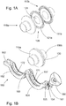
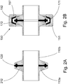
- Fig. 1A to Fig. 1D show perspective views of a method of connecting two ferrules (ferrule 110a and ferrule 110b) of conduits (not shown for reasons of clarity) using a clamp 150 according to the invention.
- the two ferrules 110a, 110b are separated by a gasket 120 having a central hole 121 having a diameter that is slightly larger than the inner diameter of the ferrules 110a, 110b.
- the gasket 120 comprises at both faces thereof an annular ridge (ridge 121a is visible in Fig. 1A ) that is received in a corresponding annular recess (annular recess 111b is visible in Fig. 1A ) of the ferrules. This helps to center the gasket 120 between the ferrules 110a, 110b and thus to center the hole 121 ( Fig. 1B ).
- a clamp 150 is used to hold the assembly of the ferrules 110a, 110b and the gasket 120 together.
- the clamp 150 comprises a first arm 151 and a second arm 152.
- the arms of a clamp may be separate pieces, but in the embodiment discussed here they are capable of hinging at first ends of said arms 151, 152 at hinge 153.
- the arms 151, 152 are typically made of metal. In the art such clamping arms are also referred to as shells or clamping members.
- the second end of the first arm 151 is forked comprising two prongs to provide a first aperture 161 that is provided with a threaded rod 154 capable of hinging about pin 155 held by the prongs at a first end thereof.
- the threaded rod 154 is provided with a nut 156 for tightening the clamp 150.
- the second arm 152 also has a forked second end comprising two prongs providing a second aperture 162 for receiving the threaded rod 154 and to provide a contact surface for the nut 156 when the clamp 150 is tightened.
- the first arm 151 comprises a first groove 171 and the second arm 152 comprises a second groove 172 as recesses for receiving part of the circumference of the assembly of both ferrules 110a, 110b and the gasket 120 in a closed state of the clamp (the closed state is shown Fig 1D ).
- the clamp 150 according to the present invention comprises an elastomeric lining 157, here of silicone having a thickness of 1.5 mm.
- Fig. 1C shows that the assembly of both ferrules 110a, 110b and the gasket 120 is received in the first groove 171 of the first arm 151 over part of the circumference thereof, in contact with the elastomeric lining 157.
- the second arm 152 is rotated using the hinge 153, the threaded rod 154 is pivoted so as to receive it in the second aperture 162 of the second arm 152 and the nut 156 is tightened ( Fig. 1D ).
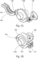
- Fig. 2A and Fig. 2B show a cross-sectional view through an assembly of two ferrules 110a, 110b and a gasket 120 without a clamp 150 and with a clamp 150 respectively.
- a ferrule 110 comprises a flange 212 that tapers to a reduced thickness towards the circumference of the flange 212.
- the grooves provided with lining 157 of the arms are also tapered towards the circumference of the closed clamp 150.
Landscapes
- Engineering & Computer Science (AREA)
- Health & Medical Sciences (AREA)
- General Engineering & Computer Science (AREA)
- Heart & Thoracic Surgery (AREA)
- Mechanical Engineering (AREA)
- General Health & Medical Sciences (AREA)
- Pulmonology (AREA)
- Anesthesiology (AREA)
- Biomedical Technology (AREA)
- Hematology (AREA)
- Life Sciences & Earth Sciences (AREA)
- Animal Behavior & Ethology (AREA)
- Public Health (AREA)
- Veterinary Medicine (AREA)
- Epidemiology (AREA)
- Gasket Seals (AREA)
Claims (8)
- Procédé destiné à relier deux conduits d'un équipement qui doit être stérilisé, chaque conduit comprenant une bague à une extrémité libre dudit conduit ; dans lequel un joint d'étanchéité statique (120) qui comprend un trou de passage est prévu entre les bagues (110a, 110b) des conduits et un collier (150) est utilisé pour le serrage (150) des bagues (110a, 110b) l'une contre l'autre, ledit collier (150) comprenant deux bras (151, 152), chaque bras comprenant un évidement (171, 172) destiné à la réception d'un tronçon circonférentiel des bagues (110a, 110b) ;
dans lequel, dans un état dans lequel les bagues (110a, 110b) sont serrées par le collier (150), les bagues (110a, 110b) procurent un passage et la surface interne du trou de passage du joint d'étanchéité statique (120), après le serrage, est disposé à fleur avec la paroi interne du passage procuré par les bagues (110a, 110b), et le joint d'étanchéité statique (120) est capable de subir un gonflement à l'intérieur dudit passage par l'intermédiaire d'une élévation temporaire de la température ;
caractérisé en ce que l'on prévoit un élément résilient (157) dans l'évidement (171, 172) d'au moins un bras du collier (150) entre ledit au moins un bras et les bagues (110a, 110b) ; dans lequel l'élément résilient (157) représente un revêtement intérieur élastomère (157) ; dans lequel l'évidement (171, 172) d'au moins un bras du collier (150) comprend ledit revêtement intérieur élastomère. - Procédé selon la revendication 1, dans lequel l'épaisseur du revêtement intérieur élastomère s'élève à au moins 0,7 mm, de préférence à au moins 1 mm.
- Procédé selon la revendication 1 ou 2, dans lequel l'épaisseur du revêtement intérieur élastomère est inférieure à 10 mm, de préférence inférieure à 6 mm.
- Procédé selon l'une quelconque des revendications précédentes, dans lequel l'élastomère représente du silicone.
- Procédé selon l'une quelconque des revendications précédentes, dans lequel le collier (150) comprenant deux bras (151, 152) représente un collier (150) qui comprend un premier bras (151) et un deuxième bras (152), chacun desdits bras (151, 152) comprenant un premier tronçon terminal et un deuxième tronçon terminal et, entre ledit premier tronçon terminal et ledit deuxième tronçon terminal, un troisième tronçon, ledit troisième tronçon comprenant :- un premier tronçon faisant office de paroi qui s'étend entre ledit premier tronçon terminal et ledit deuxième tronçon terminal ;- un deuxième tronçon faisant office de paroi qui s'étend entre ledit premier tronçon terminal et ledit deuxième tronçon terminal ; et- un troisième tronçon de liaison qui relie le premier tronçon faisant office de paroi et le deuxième tronçon faisant office de paroi ; une première face du premier tronçon faisant office de paroi, une première face du troisième tronçon de liaison et une première face du deuxième tronçon faisant office de paroi définissant une rainure ; dans lequel la première face du premier tronçon faisant office de paroi et la première face du deuxième tronçon faisant office de paroi définissent la rainure sous la forme d'un rétrécissement qui s'étend dans la direction de la première face du troisième tronçon de liaison ;dans lequel
au moins un desdits premiers tronçons terminaux peut être relié de manière amovible :- dans le but de verrouiller le collier (150) dans un premier état fermé ; et- dans le but d'ouvrir le collier (150) en définissant un deuxième état du collier (150) ;dans lequel, en ce qui concerne au moins un bras (151, 152), au moins une première face choisie parmi i) la première face du premier tronçon faisant office de paroi et ii) la première face du deuxième tronçon faisant office de paroi comprend le revêtement intérieur élastomère (157). - Procédé selon la revendication 5, dans lequel le premier tronçon terminal et le deuxième tronçon terminal sont reliés en utilisant une articulation (153).
- Procédé selon l'une quelconque des revendications précédentes, dans lequel le procédé comprend en outre l'étape dans laquelle on stérilise l'équipement.
- Procédé selon la revendication 7, dans lequel la stérilisation est mise en œuvre en utilisant de la vapeur.
Applications Claiming Priority (1)
| Application Number | Priority Date | Filing Date | Title |
|---|---|---|---|
| NL2016906A NL2016906B1 (en) | 2016-06-07 | 2016-06-07 | A method of connecting two conduits, and a clamp suitable for said method |
Publications (2)
| Publication Number | Publication Date |
|---|---|
| EP3255331A1 EP3255331A1 (fr) | 2017-12-13 |
| EP3255331B1 true EP3255331B1 (fr) | 2021-03-31 |
Family
ID=59021404
Family Applications (1)
| Application Number | Title | Priority Date | Filing Date |
|---|---|---|---|
| EP17174666.2A Active EP3255331B1 (fr) | 2016-06-07 | 2017-06-07 | Procédé permettant de raccorder deux conduits d'équipement à stériliser |
Country Status (3)
| Country | Link |
|---|---|
| EP (1) | EP3255331B1 (fr) |
| DK (1) | DK3255331T3 (fr) |
| NL (1) | NL2016906B1 (fr) |
Families Citing this family (3)
| Publication number | Priority date | Publication date | Assignee | Title |
|---|---|---|---|---|
| DE102019005004A1 (de) * | 2019-07-17 | 2021-01-21 | Pharmatec GmbH | Vorrichtung und Verfahren zur Stabilisierung von elastomeren Kompensatoren während der Sterilisierungsphase |
| US11965613B2 (en) * | 2020-10-27 | 2024-04-23 | Zeta Gmbh | System and a method for providing a sterile fluid connection between a first fluid channel and a second fluid channel |
| DE102021202883A1 (de) * | 2021-03-24 | 2022-09-29 | Glatt Gesellschaft Mit Beschränkter Haftung | System mit einer Vorrichtung zur Herstellung einer Rohrleitungseinheit und Verfahren zur Herstellung einer Rohrleitungseinheit |
Family Cites Families (5)
| Publication number | Priority date | Publication date | Assignee | Title |
|---|---|---|---|---|
| US3042430A (en) * | 1958-08-25 | 1962-07-03 | Poly Ind Inc | Fast action coupling and clamping assembly |
| US4438960A (en) * | 1982-07-16 | 1984-03-27 | Alcolite Products Corp. | Clamping & sealing system for flanged ducts |
| DE102008026563A1 (de) * | 2008-06-03 | 2009-12-17 | Bernd Hansen | Klemmverbinder zum Zusammenspannen von Verbindungsstutzen an Rohrleitungen |
| US20120074694A1 (en) * | 2009-06-08 | 2012-03-29 | Hygienic Design Group Llc | Self-aligning sanitary pipe joints and related systems |
| US8590944B2 (en) * | 2010-04-15 | 2013-11-26 | GM Global Technology Operations LLC | Band clamp having radial alignment feature |
-
2016
- 2016-06-07 NL NL2016906A patent/NL2016906B1/en not_active IP Right Cessation
-
2017
- 2017-06-07 EP EP17174666.2A patent/EP3255331B1/fr active Active
- 2017-06-07 DK DK17174666.2T patent/DK3255331T3/da active
Non-Patent Citations (1)
| Title |
|---|
| None * |
Also Published As
| Publication number | Publication date |
|---|---|
| NL2016906B1 (en) | 2017-12-13 |
| DK3255331T3 (da) | 2021-06-28 |
| EP3255331A1 (fr) | 2017-12-13 |
Similar Documents
| Publication | Publication Date | Title |
|---|---|---|
| US7591489B2 (en) | Detachable pipe joint | |
| US6830268B2 (en) | Pipe repair clamp | |
| US5476292A (en) | Pipe couplings | |
| US2688500A (en) | Coupling for pipes | |
| KR102107324B1 (ko) | 스프링클러 어댑터 및 파이프 플러그 | |
| EP3255331B1 (fr) | Procédé permettant de raccorder deux conduits d'équipement à stériliser | |
| US20120074694A1 (en) | Self-aligning sanitary pipe joints and related systems | |
| JPH07158783A (ja) | 締め付けフランジ型管取付け組立体 | |
| HK1225781B (zh) | 用於将pex管材与包括夹具的配件相连的连接系统 | |
| TW201730470A (zh) | 轉接頭之連接器 | |
| US5845386A (en) | Method for connecting a multiple-piece elbow assembly | |
| GB2349189A (en) | Pipe collar | |
| CA2325498A1 (fr) | Joint d'etancheite pour raccord de tuyauterie | |
| CA2918203C (fr) | Dispositif de capsulage de raccord de tuyau | |
| US3917324A (en) | Pipe joint | |
| TW202120847A (zh) | 出口管聯結器 | |
| US10927986B2 (en) | Universal device for the replacement of worn or lacerated parts of connecting conduits between components of climate control, cooling or hydraulic systems | |
| US2788993A (en) | Hose coupling with part spherical joining ring | |
| CN108884954B (zh) | 带有指示器的锁定管道接头装置 | |
| CA2458788C (fr) | Bride amelioree de reparation des tuyaux | |
| KR101452357B1 (ko) | 관이음 장치 | |
| KR20210066522A (ko) | 관 이음 장치 | |
| JP7364412B2 (ja) | 管継手とパイプの接続構造及び接続方法 | |
| CN117072774A (zh) | 推入式接头 | |
| KR101960492B1 (ko) | 무용접 파이프 이음구 |
Legal Events
| Date | Code | Title | Description |
|---|---|---|---|
| PUAI | Public reference made under article 153(3) epc to a published international application that has entered the european phase |
Free format text: ORIGINAL CODE: 0009012 |
|
| STAA | Information on the status of an ep patent application or granted ep patent |
Free format text: STATUS: THE APPLICATION HAS BEEN PUBLISHED |
|
| AK | Designated contracting states |
Kind code of ref document: A1 Designated state(s): AL AT BE BG CH CY CZ DE DK EE ES FI FR GB GR HR HU IE IS IT LI LT LU LV MC MK MT NL NO PL PT RO RS SE SI SK SM TR |
|
| AX | Request for extension of the european patent |
Extension state: BA ME |
|
| STAA | Information on the status of an ep patent application or granted ep patent |
Free format text: STATUS: REQUEST FOR EXAMINATION WAS MADE |
|
| 17P | Request for examination filed |
Effective date: 20180608 |
|
| RBV | Designated contracting states (corrected) |
Designated state(s): AL AT BE BG CH CY CZ DE DK EE ES FI FR GB GR HR HU IE IS IT LI LT LU LV MC MK MT NL NO PL PT RO RS SE SI SK SM TR |
|
| RAP1 | Party data changed (applicant data changed or rights of an application transferred) |
Owner name: ULTRAPHARMA HOLDING BV |
|
| STAA | Information on the status of an ep patent application or granted ep patent |
Free format text: STATUS: EXAMINATION IS IN PROGRESS |
|
| 17Q | First examination report despatched |
Effective date: 20200204 |
|
| GRAP | Despatch of communication of intention to grant a patent |
Free format text: ORIGINAL CODE: EPIDOSNIGR1 |
|
| STAA | Information on the status of an ep patent application or granted ep patent |
Free format text: STATUS: GRANT OF PATENT IS INTENDED |
|
| RIC1 | Information provided on ipc code assigned before grant |
Ipc: F16L 23/10 20060101AFI20201002BHEP Ipc: A61M 39/12 20060101ALI20201002BHEP Ipc: F16L 23/22 20060101ALI20201002BHEP Ipc: A61M 39/18 20060101ALI20201002BHEP Ipc: F16J 15/06 20060101ALI20201002BHEP |
|
| INTG | Intention to grant announced |
Effective date: 20201023 |
|
| GRAS | Grant fee paid |
Free format text: ORIGINAL CODE: EPIDOSNIGR3 |
|
| GRAA | (expected) grant |
Free format text: ORIGINAL CODE: 0009210 |
|
| STAA | Information on the status of an ep patent application or granted ep patent |
Free format text: STATUS: THE PATENT HAS BEEN GRANTED |
|
| AK | Designated contracting states |
Kind code of ref document: B1 Designated state(s): AL AT BE BG CH CY CZ DE DK EE ES FI FR GB GR HR HU IE IS IT LI LT LU LV MC MK MT NL NO PL PT RO RS SE SI SK SM TR |
|
| REG | Reference to a national code |
Ref country code: GB Ref legal event code: FG4D Ref country code: CH Ref legal event code: EP |
|
| REG | Reference to a national code |
Ref country code: DE Ref legal event code: R096 Ref document number: 602017035549 Country of ref document: DE Ref country code: AT Ref legal event code: REF Ref document number: 1377301 Country of ref document: AT Kind code of ref document: T Effective date: 20210415 |
|
| REG | Reference to a national code |
Ref country code: IE Ref legal event code: FG4D |
|
| REG | Reference to a national code |
Ref country code: DK Ref legal event code: T3 Effective date: 20210623 |
|
| REG | Reference to a national code |
Ref country code: NL Ref legal event code: FP |
|
| REG | Reference to a national code |
Ref country code: SE Ref legal event code: TRGR |
|
| REG | Reference to a national code |
Ref country code: LT Ref legal event code: MG9D |
|
| PG25 | Lapsed in a contracting state [announced via postgrant information from national office to epo] |
Ref country code: NO Free format text: LAPSE BECAUSE OF FAILURE TO SUBMIT A TRANSLATION OF THE DESCRIPTION OR TO PAY THE FEE WITHIN THE PRESCRIBED TIME-LIMIT Effective date: 20210630 Ref country code: HR Free format text: LAPSE BECAUSE OF FAILURE TO SUBMIT A TRANSLATION OF THE DESCRIPTION OR TO PAY THE FEE WITHIN THE PRESCRIBED TIME-LIMIT Effective date: 20210331 Ref country code: FI Free format text: LAPSE BECAUSE OF FAILURE TO SUBMIT A TRANSLATION OF THE DESCRIPTION OR TO PAY THE FEE WITHIN THE PRESCRIBED TIME-LIMIT Effective date: 20210331 Ref country code: BG Free format text: LAPSE BECAUSE OF FAILURE TO SUBMIT A TRANSLATION OF THE DESCRIPTION OR TO PAY THE FEE WITHIN THE PRESCRIBED TIME-LIMIT Effective date: 20210630 |
|
| PG25 | Lapsed in a contracting state [announced via postgrant information from national office to epo] |
Ref country code: LV Free format text: LAPSE BECAUSE OF FAILURE TO SUBMIT A TRANSLATION OF THE DESCRIPTION OR TO PAY THE FEE WITHIN THE PRESCRIBED TIME-LIMIT Effective date: 20210331 Ref country code: RS Free format text: LAPSE BECAUSE OF FAILURE TO SUBMIT A TRANSLATION OF THE DESCRIPTION OR TO PAY THE FEE WITHIN THE PRESCRIBED TIME-LIMIT Effective date: 20210331 |
|
| REG | Reference to a national code |
Ref country code: AT Ref legal event code: MK05 Ref document number: 1377301 Country of ref document: AT Kind code of ref document: T Effective date: 20210331 |
|
| PG25 | Lapsed in a contracting state [announced via postgrant information from national office to epo] |
Ref country code: EE Free format text: LAPSE BECAUSE OF FAILURE TO SUBMIT A TRANSLATION OF THE DESCRIPTION OR TO PAY THE FEE WITHIN THE PRESCRIBED TIME-LIMIT Effective date: 20210331 Ref country code: CZ Free format text: LAPSE BECAUSE OF FAILURE TO SUBMIT A TRANSLATION OF THE DESCRIPTION OR TO PAY THE FEE WITHIN THE PRESCRIBED TIME-LIMIT Effective date: 20210331 Ref country code: LT Free format text: LAPSE BECAUSE OF FAILURE TO SUBMIT A TRANSLATION OF THE DESCRIPTION OR TO PAY THE FEE WITHIN THE PRESCRIBED TIME-LIMIT Effective date: 20210331 Ref country code: AT Free format text: LAPSE BECAUSE OF FAILURE TO SUBMIT A TRANSLATION OF THE DESCRIPTION OR TO PAY THE FEE WITHIN THE PRESCRIBED TIME-LIMIT Effective date: 20210331 Ref country code: SM Free format text: LAPSE BECAUSE OF FAILURE TO SUBMIT A TRANSLATION OF THE DESCRIPTION OR TO PAY THE FEE WITHIN THE PRESCRIBED TIME-LIMIT Effective date: 20210331 |
|
| PG25 | Lapsed in a contracting state [announced via postgrant information from national office to epo] |
Ref country code: SK Free format text: LAPSE BECAUSE OF FAILURE TO SUBMIT A TRANSLATION OF THE DESCRIPTION OR TO PAY THE FEE WITHIN THE PRESCRIBED TIME-LIMIT Effective date: 20210331 Ref country code: RO Free format text: LAPSE BECAUSE OF FAILURE TO SUBMIT A TRANSLATION OF THE DESCRIPTION OR TO PAY THE FEE WITHIN THE PRESCRIBED TIME-LIMIT Effective date: 20210331 Ref country code: PL Free format text: LAPSE BECAUSE OF FAILURE TO SUBMIT A TRANSLATION OF THE DESCRIPTION OR TO PAY THE FEE WITHIN THE PRESCRIBED TIME-LIMIT Effective date: 20210331 Ref country code: PT Free format text: LAPSE BECAUSE OF FAILURE TO SUBMIT A TRANSLATION OF THE DESCRIPTION OR TO PAY THE FEE WITHIN THE PRESCRIBED TIME-LIMIT Effective date: 20210802 Ref country code: IS Free format text: LAPSE BECAUSE OF FAILURE TO SUBMIT A TRANSLATION OF THE DESCRIPTION OR TO PAY THE FEE WITHIN THE PRESCRIBED TIME-LIMIT Effective date: 20210731 |
|
| REG | Reference to a national code |
Ref country code: DE Ref legal event code: R097 Ref document number: 602017035549 Country of ref document: DE |
|
| PG25 | Lapsed in a contracting state [announced via postgrant information from national office to epo] |
Ref country code: ES Free format text: LAPSE BECAUSE OF FAILURE TO SUBMIT A TRANSLATION OF THE DESCRIPTION OR TO PAY THE FEE WITHIN THE PRESCRIBED TIME-LIMIT Effective date: 20210331 Ref country code: AL Free format text: LAPSE BECAUSE OF FAILURE TO SUBMIT A TRANSLATION OF THE DESCRIPTION OR TO PAY THE FEE WITHIN THE PRESCRIBED TIME-LIMIT Effective date: 20210331 Ref country code: MC Free format text: LAPSE BECAUSE OF FAILURE TO SUBMIT A TRANSLATION OF THE DESCRIPTION OR TO PAY THE FEE WITHIN THE PRESCRIBED TIME-LIMIT Effective date: 20210331 |
|
| PLBE | No opposition filed within time limit |
Free format text: ORIGINAL CODE: 0009261 |
|
| STAA | Information on the status of an ep patent application or granted ep patent |
Free format text: STATUS: NO OPPOSITION FILED WITHIN TIME LIMIT |
|
| 26N | No opposition filed |
Effective date: 20220104 |
|
| PG25 | Lapsed in a contracting state [announced via postgrant information from national office to epo] |
Ref country code: LU Free format text: LAPSE BECAUSE OF NON-PAYMENT OF DUE FEES Effective date: 20210607 |
|
| PG25 | Lapsed in a contracting state [announced via postgrant information from national office to epo] |
Ref country code: IS Free format text: LAPSE BECAUSE OF FAILURE TO SUBMIT A TRANSLATION OF THE DESCRIPTION OR TO PAY THE FEE WITHIN THE PRESCRIBED TIME-LIMIT Effective date: 20210731 |
|
| PG25 | Lapsed in a contracting state [announced via postgrant information from national office to epo] |
Ref country code: HU Free format text: LAPSE BECAUSE OF FAILURE TO SUBMIT A TRANSLATION OF THE DESCRIPTION OR TO PAY THE FEE WITHIN THE PRESCRIBED TIME-LIMIT; INVALID AB INITIO Effective date: 20170607 |
|
| PG25 | Lapsed in a contracting state [announced via postgrant information from national office to epo] |
Ref country code: CY Free format text: LAPSE BECAUSE OF FAILURE TO SUBMIT A TRANSLATION OF THE DESCRIPTION OR TO PAY THE FEE WITHIN THE PRESCRIBED TIME-LIMIT Effective date: 20210331 |
|
| PG25 | Lapsed in a contracting state [announced via postgrant information from national office to epo] |
Ref country code: GR Free format text: LAPSE BECAUSE OF FAILURE TO SUBMIT A TRANSLATION OF THE DESCRIPTION OR TO PAY THE FEE WITHIN THE PRESCRIBED TIME-LIMIT Effective date: 20210331 |
|
| PG25 | Lapsed in a contracting state [announced via postgrant information from national office to epo] |
Ref country code: MK Free format text: LAPSE BECAUSE OF FAILURE TO SUBMIT A TRANSLATION OF THE DESCRIPTION OR TO PAY THE FEE WITHIN THE PRESCRIBED TIME-LIMIT Effective date: 20210331 |
|
| PG25 | Lapsed in a contracting state [announced via postgrant information from national office to epo] |
Ref country code: MT Free format text: LAPSE BECAUSE OF FAILURE TO SUBMIT A TRANSLATION OF THE DESCRIPTION OR TO PAY THE FEE WITHIN THE PRESCRIBED TIME-LIMIT Effective date: 20210331 |
|
| PGFP | Annual fee paid to national office [announced via postgrant information from national office to epo] |
Ref country code: DE Payment date: 20250612 Year of fee payment: 9 |
|
| PGFP | Annual fee paid to national office [announced via postgrant information from national office to epo] |
Ref country code: GB Payment date: 20250617 Year of fee payment: 9 Ref country code: DK Payment date: 20250617 Year of fee payment: 9 |
|
| PGFP | Annual fee paid to national office [announced via postgrant information from national office to epo] |
Ref country code: NL Payment date: 20250612 Year of fee payment: 9 Ref country code: BE Payment date: 20250612 Year of fee payment: 9 |
|
| PGFP | Annual fee paid to national office [announced via postgrant information from national office to epo] |
Ref country code: FR Payment date: 20250617 Year of fee payment: 9 |
|
| PGFP | Annual fee paid to national office [announced via postgrant information from national office to epo] |
Ref country code: IE Payment date: 20250617 Year of fee payment: 9 |
|
| PGFP | Annual fee paid to national office [announced via postgrant information from national office to epo] |
Ref country code: SE Payment date: 20250617 Year of fee payment: 9 |
|
| PGFP | Annual fee paid to national office [announced via postgrant information from national office to epo] |
Ref country code: IT Payment date: 20250626 Year of fee payment: 9 |
|
| PGFP | Annual fee paid to national office [announced via postgrant information from national office to epo] |
Ref country code: CH Payment date: 20250701 Year of fee payment: 9 |
|
| PG25 | Lapsed in a contracting state [announced via postgrant information from national office to epo] |
Ref country code: TR Free format text: LAPSE BECAUSE OF FAILURE TO SUBMIT A TRANSLATION OF THE DESCRIPTION OR TO PAY THE FEE WITHIN THE PRESCRIBED TIME-LIMIT Effective date: 20210331 |