EP3255278A1 - Rückschlagventil für eine vakuumpumpe - Google Patents
Rückschlagventil für eine vakuumpumpe Download PDFInfo
- Publication number
- EP3255278A1 EP3255278A1 EP17169915.0A EP17169915A EP3255278A1 EP 3255278 A1 EP3255278 A1 EP 3255278A1 EP 17169915 A EP17169915 A EP 17169915A EP 3255278 A1 EP3255278 A1 EP 3255278A1
- Authority
- EP
- European Patent Office
- Prior art keywords
- hold
- check valve
- spring strip
- curvature
- screw
- Prior art date
- Legal status (The legal status is an assumption and is not a legal conclusion. Google has not performed a legal analysis and makes no representation as to the accuracy of the status listed.)
- Granted
Links
Images
Classifications
-
- F—MECHANICAL ENGINEERING; LIGHTING; HEATING; WEAPONS; BLASTING
- F04—POSITIVE - DISPLACEMENT MACHINES FOR LIQUIDS; PUMPS FOR LIQUIDS OR ELASTIC FLUIDS
- F04B—POSITIVE-DISPLACEMENT MACHINES FOR LIQUIDS; PUMPS
- F04B39/00—Component parts, details, or accessories, of pumps or pumping systems specially adapted for elastic fluids, not otherwise provided for in, or of interest apart from, groups F04B25/00 - F04B37/00
- F04B39/10—Adaptations or arrangements of distribution members
- F04B39/1073—Adaptations or arrangements of distribution members the members being reed valves
-
- F—MECHANICAL ENGINEERING; LIGHTING; HEATING; WEAPONS; BLASTING
- F04—POSITIVE - DISPLACEMENT MACHINES FOR LIQUIDS; PUMPS FOR LIQUIDS OR ELASTIC FLUIDS
- F04B—POSITIVE-DISPLACEMENT MACHINES FOR LIQUIDS; PUMPS
- F04B37/00—Pumps having pertinent characteristics not provided for in, or of interest apart from, groups F04B25/00 - F04B35/00
- F04B37/10—Pumps having pertinent characteristics not provided for in, or of interest apart from, groups F04B25/00 - F04B35/00 for special use
- F04B37/14—Pumps having pertinent characteristics not provided for in, or of interest apart from, groups F04B25/00 - F04B35/00 for special use to obtain high vacuum
Definitions
- the present invention relates to a check valve for a vacuum pump, comprising a housing, a spring strip and a hold-down, according to the preamble of claim 1.
- the invention also relates to a vacuum pump with at least one such check valve.
- a generic check valve for a vacuum pump which comprises a housing, a hold-down and a valve opening covering a spring strip.
- the spring strip and the hold-down are fixed by a common screw on the housing.
- the hold-down has a screw portion and a contact portion, which merge into one another via a curved intermediate portion, ie concretely a curvature.
- the hold-down is screwed to the screw section on the screw on the housing.
- the hold-down has in its contact section a slot-shaped recess, which is intended in particular to prevent breakage of the hold-down for larger subsidized lubricating oil.
- a wing vacuum pump having a discharge port for discharging sucked air and a diaphragm valve member.
- the diaphragm valve part has a first diaphragm valve, which specifically covers the valve opening, that is to say the discharge port, and a second diaphragm valve which covers the first diaphragm valve.
- Both diaphragm valves have different resonance frequencies due to different thicknesses. As a result, in particular an unpleasant noise is to be at least reduced.
- check valves known from the prior art have the problem that dirt particles can collect between a hold-down device and a spring strip, that is to say a valve closure body, and can cause damage if the check valve is permanently opened.
- the present invention is therefore concerned with the problem of providing for a check valve of the generic type an improved or at least one alternative embodiment, which is in particular more resistant.
- the present invention is based on the general idea to provide between a spring strip and a deflecting movement of this spring strip holding down a space formed by a buckle of the hold-down, which allows a receptacle for dirt between the hold-down and the spring strip and wherein in the region of this curvature simultaneously Opening is provided, via which corresponding dirt particles can be removed immediately.
- the check valve according to the invention for a vacuum pump in this case comprises a housing, the hold-down device described above and the above-described and a valve opening covering spring strip.
- the spring strip and the hold-down are fastened via a common screw on the housing of the check valve.
- the hold-down itself has a screw section and a ganbrough, which merge into one another via the above-described curvature.
- the hold-down is screwed to the housing via the screw section and the screw.
- the curvature is now oriented in such a way that it forms a cavity between the hold-down device and the spring strip, thereby enabling a pick-up of dirt or dirt particles.
- at least one opening is additionally provided according to the invention, which allows an immediate removal of the dirt particles and thereby a long-term trouble-free operation of the check valve.
- the hold-down device is bent in the contact section.
- a bend for example, an opening behavior of the spring strip can be influenced.
- the hold-down serves only as a stop on which the spring strip applies from a certain opening angle.
- the spring strip engages in the contact section of the hold-down device when the check valve is open.
- the hold-down usually has an arcuate shape pointing away from the valve opening, so that the spring strip does not yet rest against the abutment section of the hold-down during a slight opening movement, but at a larger opening movement.
- the curvature has a radius r between 1.5 and 3.0 mm.
- a sufficiently large volume or a sufficiently large cavity for receiving dirt particles can be created. This can also for the proper operation of the Inventive check valve required size of the cavity to accommodate dirt particles are guaranteed.
- the hold-down is made of a spring steel band.
- the hold-down can not only be produced inexpensively, but at the same time with the properties required for a precisely predefined opening movement.
- Both the spring strip and the hold-down can be formed as a stamped part and thereby be produced as inexpensively as high quality.
- the hold-down is wider than the spring strip at least in the region of its contact section. This also allows an opening characteristic of the check valve to be predefined exactly.
- the holding-down device is at a distance a from the spring strip spaced with a closed check valve in the contact section.
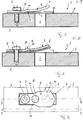
- FIGS. 1 to 3 An inventive check valve 1 for a vacuum pump 2, a housing 3, a spring strip 4 and a hold-5.
- the spring strip 4 covers a valve opening 6 and closes this tight (see FIG. 1 ).
- the spring strip 4 and the hold-down 5 are fixed by a common screw 7 on the housing 3, wherein the hold-down 5 has a screw portion 8 and a contact portion 9, which merge into one another via a curvature 10.
- the hold-down 5 is at the screw section 8 via the screw 7 with the Housing 3 bolted.
- the curvature 10 is now oriented in such a way that it forms a receptacle 11 for dirt particles between the hold-down 5 and the spring strip 4, the hold-down 5 also having an opening 12 in the region of the curvature 10, via which dirt particles reaching the receptacle 11 again can be discharged.
- the check valve 1 is shown in the closed state, in which the spring strip 4 rests tightly on the valve opening 6.
- a contact between the spring strip 4 and the contact portion 9 of the blank holder 5 takes place exclusively when the check valve 1 is open, as shown in the FIG. 2 is shown.
- the curvature 10 has a radius r between 1.5 and 3 mm, whereby the receptacle 11 has sufficient volume for receiving dirt particles.
- the opening 12 in the region of the curvature 10 is here not to be underestimated cross-sectional weakening of the hold 5, wherein depending on the size of the opening 12, the Auslenk characterizing the spring strip 4 can be influenced when opening the check valve 1.
- the hold-down 5 is made of a spring steel strip, for example, punched out of it and simultaneously formed, whereby the hold-down 5 can be made of high quality and cost overall.
- the spring strip 4 is made, the thickness of which is usually significantly lower than that of the blank holder. 4
- this is formed in the contact section 9 continuously closed, that is, has no openings, whereby a flat concerns of the spring strip 4 can be made in the open state.
- valve opening 6 for example, an exhaust valve of a vacuum pump 2
- the check valve 1 cost and at the same time wear-resistant to be closed, since the provided between the spring strip 4 and the hold-5 in the buckle 10 receptacle 11 of the opening 12 a long-term investment of Prevent dirt particles between the hold-down 5 and the spring strip 4 reliably, which in particular the resulting damage to the holddown 5 can be reliably avoided up to a break thereof.
- the opening 12 is limited exclusively to the region of the curvature 10 and ends before the contact section 9.
- the hold-5 is at a closed check valve 1 in the contact section 9, adjacent to the buckle 10, with a distance a from the spring strip 4 spaced, for example 0, 8 mm to 2.0 mm, this distance a allows easy entry of dirt particles in the arranged between the hold-5 and the spring strip 4 receptacle 10 and a discharge of this dirt particles on the opening 12.
- the hold-5 is wider at least in the region of the contact portion 9 as the spring strip 4, whereby a reliable support of the spring strip 4 in the open state is possible.
- the check valve 1 of the invention has the great advantage that also long term between the spring strip 4 and the hold-down. 5 can accumulate no dirt particles, which both lead to an impairment of the life of the check valve 1 and can negatively affect its opening and closing ability.
Landscapes
- Engineering & Computer Science (AREA)
- Mechanical Engineering (AREA)
- General Engineering & Computer Science (AREA)
- Check Valves (AREA)
- Details Of Valves (AREA)
- Applications Or Details Of Rotary Compressors (AREA)
Abstract
Description
- Die vorliegende Erfindung betrifft ein Rückschlagventil für eine Vakuumpumpe, umfassend ein Gehäuse, einen Federstreifen und einen Niederhalter, gemäß dem Oberbegriff des Anspruchs 1. Die Erfindung betrifft außerdem eine Vakuumpumpe mit zumindest einem solchen Rückschlagventil.
- Aus der
DE 195 24 906 A1 ist ein gattungsgemäßes Rückschlagventil für eine Vakuumpumpe bekannt, welches ein Gehäuse, einen Niederhalter sowie einen eine Ventilöffnung überdeckenden Federstreifen umfasst. Der Federstreifen und der Niederhalter sind dabei über eine gemeinsame Schraube am Gehäuse festgelegt. Darüber hinaus besitzt der Niederhalter einen Schraubabschnitt und einen Anlageabschnitt, die über einen gewölbten Zwischenabschnitt, das heißt konkret eine Wölbung, ineinander übergehen. Der Niederhalter ist dabei am Schraubabschnitt über die Schraube am Gehäuse angeschraubt. Der Niederhalter besitzt in seinem Anlageabschnitt eine langlochförmige Ausnehmung, welche insbesondere ein Brechen des Niederhalters bei größeren geförderten Schmierölanteilen vermeiden soll. - Aus der
DE 10 2015 100 987 A1 ist eine Flügelunterdruckpumpe mit einem Abgabeanschluss zum Abgeben von angesaugter Luft und einem Membranventilteil bekannt. Der Membranventilteil weist ein erstes Membranventil auf, das die Ventilöffnung, das heißt konkret den Abgabeanschluss abdeckt, sowie ein zweites Membranventil, das das erste Membranventil überdeckt. Beide Membranventile haben dabei unterschiedliche Resonanzfrequenzen aufgrund unterschiedlicher Dicken. Hierdurch soll insbesondere eine unangenehme Geräuschentwicklung zumindest reduziert werden. - Generell besteht bei den aus dem Stand der Technik bekannten Rückschlagventilen das Problem, dass sich Schmutzpartikel zwischen einem Niederhalter und einem Federstreifen, das heißt einem Ventilverschlusskörper, sammeln und bei einem ständigen Öffnen des Rückschlagventils eine Schädigung hervorrufen können.
- Die vorliegende Erfindung beschäftigt sich daher mit dem Problem, für ein Rückschlagventil der gattungsgemäßen Art eine verbesserte oder zumindest eine alternative Ausführungsform anzugeben, die insbesondere widerstandsfähiger ist.
- Dieses Problem wird erfindungsgemäß durch den Gegenstand des unabhängigen Anspruchs 1 gelöst. Vorteilhafte Ausführungsformen sind Gegenstand der abhängigen Ansprüche.
- Die vorliegende Erfindung beruht auf dem allgemeinen Gedanken, zwischen einem Federstreifen und einem eine Auslenkbewegung dieses Federstreifens begrenzenden Niederhalter einen durch eine Wölbung des Niederhalters gebildeten Raum vorzusehen, die eine Aufnahme für Schmutz zwischen dem Niederhalter und dem Federstreifen ermöglicht und wobei im Bereich dieser Wölbung gleichzeitig eine Öffnung vorgesehen ist, über welche entsprechende Schmutzpartikel sofort abgeführt werden können. Hierdurch kann insbesondere eine das Rückschlagventil langfristig schädigende Ansammlung von Schmutzpartikeln zwischen dem Federstreifen und dem Niederhalter zuverlässig vermieden werden. Das erfindungsgemäße Rückschlagventil für eine Vakuumpumpe umfasst dabei ein Gehäuse, den zuvor beschriebenen Niederhalter sowie den zuvor beschriebenen und eine Ventilöffnung überdeckenden Federstreifen. Der Federstreifen und der Niederhalter sind dabei über eine gemeinsame Schraube am Gehäuse des Rückschlagventils befestigt. Der Niederhalter selbst besitzt einen Schraubabschnitt sowie einen Anlageabschnitt, die über die zuvor beschriebene Wölbung ineinander übergehen. Der Niederhalter ist dabei über den Schraubabschnitt und die Schraube am Gehäuse angeschraubt. Erfindungsgemäß ist nun die Wölbung derart orientiert, dass sie eine Kavität zwischen dem Niederhalter und dem Federstreifen bildet und dadurch eine Aufnahme von Schmutz bzw. Schmutzpartikeln ermöglicht. Im Bereich dieser Wölbung ist zusätzlich erfindungsgemäß zumindest eine Öffnung vorgesehen, die eine sofortige Entfernung der Schmutzpartikel und dadurch einen langfristig störungsfreien Betrieb des Rückschlagventils ermöglicht.
- Bei einer vorteilhaften Weiterbildung der erfindungsgemäßen Lösung ist der Niederhalter im Anlageabschnitt gebogen. Über eine derartige Biegung kann beispielsweise ein Öffnungsverhalten des Federstreifens beeinflusst werden. Dabei ist denkbar, dass der Niederhalter lediglich als Anschlag dient, an welchen sich der Federstreifen ab einem gewissen Öffnungswinkel anlegt.
- Gemäß einer besonders bevorzugten Ausführungsform der erfindungsgemäßen Lösung legt sich dabei der Federstreifen bei geöffnetem Rückschlagventil ausschließlich im Anlageabschnitt des Niederhalters an diesen an. Der Niederhalter weist dabei im Bereich seines Anlageabschnitts üblicherweise eine von der Ventilöffnung wegweisende, gebogene Form, so dass der Federstreifen bei einer geringen Öffnungsbewegung noch nicht am Anlageabschnitt des Niederhalters anliegt, wohl aber bei einer größeren Öffnungsbewegung.
- Zweckmäßig weist die Wölbung einen Radius r zwischen 1,5 und 3,0 mm auf. Durch einen derart gewählten Radius r kann insbesondere ein genügend großes Volumen bzw. eine genügend große Kavität zur Aufnahme von Schmutzpartikeln geschaffen werden. Auch hierdurch kann die für den einwandfreien Betrieb des erfindungsgemäßen Rückschlagventils erforderliche Größe der Kavität zur Aufnahme von Schmutzpartikeln gewährleistet werden.
- Zweckmäßig ist der Niederhalter aus einem Federstahlband hergestellt. Hierdurch lässt sich der Niederhalter nicht nur kostengünstig herstellen, sondern zugleich auch mit den für eine exakt vordefinierte Öffnungsbewegung erforderlichen Eigenschaften. Sowohl der Federstreifen als auch der Niederhalter können dabei als Stanzteil ausgebildet sein und dadurch ebenso kostengünstig wie qualitativ hochwertig hergestellt werden.
- Zweckmäßig ist der Niederhalter zumindest im Bereich seines Anlageabschnitts breiter als der Federstreifen. Auch hierdurch lässt sich eine Öffnungscharakteristik des Rückschlagventils exakt vordefinieren.
- Bei einer weiteren vorteilhaften Ausführungsform der erfindungsgemäßen Lösung ist der Niederhalter bei geschlossenem Rückschlagventil im Anlageabschnitt mit einem Abstand a vom Federstreifen beabstandet. Dies ermöglicht, dass die Wölbung und die dadurch gebildete Kavität auch bei geschlossenem Rückschlagventil von außen zugänglich ist, so dass Schmutzpartikel bei geschlossenem Federstreifen und damit geschlossenem Rückschlagventil in die durch die Kavität gebildete Wölbung gelangen und durch die dort vorgesehene Öffnung wieder ausgetragen werden können, so dass sich langfristig keine Schmutzpartikel zwischen dem Federstreifen und dem Niederhalter anlagern können.
- Weitere wichtige Merkmale und Vorteile der Erfindung ergeben sich aus den Unteransprüchen, aus den Zeichnungen und aus der zugehörigen Figurenbeschreibung anhand der Zeichnungen.
- Es versteht sich, dass die vorstehend genannten und die nachstehend noch zu erläuternden Merkmale nicht nur in der jeweils angegebenen Kombination, sondern auch in anderen Kombinationen oder in Alleinstellung verwendbar sind, ohne den Rahmen der vorliegenden Erfindung zu verlassen.
- Bevorzugte Ausführungsbeispiele der Erfindung sind in den Zeichnungen dargestellt und werden in der nachfolgenden Beschreibung näher erläutert, wobei sich gleiche Bezugszeichen auf gleiche oder ähnliche oder funktional gleiche Bauteile beziehen.
- Dabei zeigen, jeweils schematisch,
- Fig. 1
- eine Schnittdarstellung durch ein erfindungsgemäßen Rückschlagventil einer Vakuumpumpe bei geschlossenem Federstreifen entlang der Schnittebene I-I,
- Fig. 2
- eine Darstellung wie in
Fig. 1 , jedoch entlang der Schnittebene II-II und bei gleichzeitig geöffnetem Rückschlagventil, - Fig. 3
- eine Draufsicht auf das erfindungsgemäße Rückschlagventil.
- Entsprechend den
Figuren 1 bis 3 , weist ein erfindungsgemäßes Rückschlagventil 1 für eine Vakuumpumpe 2 ein Gehäuse 3, einen Federstreifen 4 sowie einen Niederhalter 5 auf. Der Federstreifen 4 überdeckt dabei eine Ventilöffnung 6 und schließt diese dicht ab (vergleicheFigur 1 ). Der Federstreifen 4 und der Niederhalter 5 sind über eine gemeinsame Schraube 7 am Gehäuse 3 festgelegt, wobei der Niederhalter 5 einen Schraubabschnitt 8 und einen Anlageabschnitt 9 aufweist, die über eine Wölbung 10 ineinander übergehen. Der Niederhalter 5 ist dabei am Schraubabschnitt 8 über die Schraube 7 mit dem Gehäuse 3 verschraubt. Erfindungsgemäß ist nun die Wölbung 10 derart orientiert, dass sie eine Aufnahme 11 für Schmutzpartikel zwischen dem Niederhalter 5 und dem Federstreifen 4 bildet, wobei der Niederhalter 5 im Bereich der Wölbung 10 zugleich eine Öffnung 12 aufweist, über welche in die Aufnahme 11 gelangende Schmutzpartikel wieder ausgetragen werden können. - Gemäß der
Figur 1 ist dabei das Rückschlagventil 1 im geschlossenen Zustand gezeigt, in welchem der Federstreifen 4 dicht auf der Ventilöffnung 6 aufliegt. Demgegenüber zeigt dieFigur 2 ein geöffnetes Rückschlagventil 1, bei welchem der Federstreifen 4 von der Ventilöffnung 6 abgehoben ist und am Anlageabschnitt 9 des Niederhalters 5 anliegt. Ein Kontakt zwischen dem Federstreifen 4 und dem Anlageabschnitt 9 des Niederhalters 5 erfolgt dabei ausschließlich bei geöffnetem Rückschlagventil 1, wie dies gemäß derFigur 2 dargestellt ist. - Betrachtet man den Niederhalter 5 weiter, so kann man erkennen, dass dieser im Anlageabschnitt 9 gebogen ausgebildet ist. Die Wölbung 10 besitzt einen Radius r zwischen 1,5 und 3 mm, wodurch die Aufnahme 11 genügend Volumen zur Aufnahme von Schmutzpartikeln aufweist. Durch die Öffnung 12 im Bereich der Wölbung 10 erfolgt hier eine nicht zu unterschätzende Querschnittsschwächung des Niederhalters 5, wobei je nach Größe der Öffnung 12 die Auslenkcharakteristik des Federstreifens 4 beim Öffnen des Rückschlagventils 1 beeinflusst werden kann. Generell ist der Niederhalter 5 aus einem Federstahlband hergestellt, beispielsweise daraus ausgestanzt und gleichzeitig umgeformt, wodurch der Niederhalter 5 insgesamt qualitativ hochwertig und kostengünstig hergestellt werden kann. In ähnlicher Weise ist auch der Federstreifen 4 hergestellt, wobei dessen Dicke üblicherweise deutlich geringer ist als die des Niederhalters 4.
- Betrachtet man den Niederhalter 5 weiter, so kann man erkennen, dass dieser im Anlageabschnitt 9 durchgängig geschlossen ausgebildet ist, das heißt keinerlei Öffnungen aufweist, wodurch ein flächiges Anliegen des Federstreifens 4 im Öffnungszustand erfolgen kann.
- Mit dem erfindungsgemäßen Rückschlagventil 1 kann insbesondere eine Ventilöffnung 6, beispielsweise eines Auslassventils einer Vakuumpumpe 2, kostengünstig und zugleich verschleißbeständig verschlossen werden, da die zwischen dem Federstreifen 4 und dem Niederhalter 5 im Bereich der Wölbung 10 vorgesehene Aufnahme 11 der Öffnung 12 ein langfristiges Anlagern von Schmutzpartikeln zwischen dem Niederhalter 5 und dem Federstreifen 4 zuverlässig verhindern, wodurch insbesondere hieraus resultierende Schädigungen des Niederhalters 5 bis hin zu einem Brechen desselben zuverlässig vermieden werden können. Die Öffnung 12 ist dabei ausschließlich auf den Bereich der Wölbung 10 begrenzt und endet vor dem Anlageabschnitt 9. Der Niederhalter 5 ist bei geschlossenem Rückschlagventil 1 im Anlageabschnitt 9, angrenzend an die Wölbung 10, mit einem Abstand a vom Federstreifen 4 beabstandet, beispielsweise 0,8 mm bis 2,0 mm, wobei dieser Abstand a einen problemlosen Eintrag von Schmutzpartikeln in die zwischen dem Niederhalter 5 und dem Federstreifen 4 angeordnete Aufnahme 10 sowie einen Austrag dieser Schmutzpartikel über der Öffnung 12 ermöglicht.
- Betrachtet man noch die
Figur 3 , so kann man erkennen, dass der Niederhalter 5 zumindest im Bereich des Anlageabschnitts 9 breiter ist als der Federstreifen 4, wodurch eine zuverlässige Abstützung des Federstreifens 4 im geöffneten Zustand möglich ist. - Generell bietet das erfindungsgemäße Rückschlagventil 1 den großen Vorteil, dass sich auch langfristig zwischen dem Federstreifen 4 und dem Niederhalter 5 keine Schmutzpartikel anlagern können, die sowohl zu einer Beeinträchtigung der Lebensdauer des Rückschlagventils 1 führen als auch dessen Öffnungs- und Schließfähigkeit negativ beeinflussen können.
Claims (9)
- Rückschlagventil (1) für eine Vakuumpumpe (2), umfassend ein Gehäuse (3), einen Niederhalter (5) und einen eine Ventilöffnung (6) überdeckenden Federstreifen (4),- wobei der Federstreifen (4) und der Niederhalter (5) über eine gemeinsame Schraube (7) am Gehäuse (3) befestigt sind,- wobei der Niederhalter (5) einen Schraubabschnitt (8) und einen Anlageabschnitt (9) aufweist, die über eine Wölbung (10) ineinander übergehen,- wobei der Niederhalter (5) am Schraubabschnitt (8) über die Schraube (7) am Gehäuse (3) angeschraubt ist,dadurch gekennzeichnet,- dass die Wölbung (10) so orientiert ist, dass sie eine Aufnahme für Schmutz zwischen dem Niederhalter (5) und dem Federstreifen (4) ermöglicht,- dass der Niederhalter (5) im Bereich der Wölbung (10) eine Öffnung (12) aufweist.
- Rückschlagventil nach Anspruch 1,
dadurch gekennzeichnet, dass
der Federstreifen (4) sich bei geöffnetem Rückschlagventil (1) ausschließlich am Anlageabschnitt (9) des Niederhalters (5) anlegt. - Rückschlagventil nach Anspruch 1 oder 2,
dadurch gekennzeichnet, dass
der Anlageabschnitt (9) gebogen ist. - Rückschlagventil nach einem der Ansprüche 1 bis 3,
dadurch gekennzeichnet, dass
die Wölbung (10) einen Radius r zwischen 1,5 mm und 3 mm aufweist. - Rückschlagventil nach einem der vorhergehenden Ansprüche,
dadurch gekennzeichnet, dass
der Niederhalter (5) bei geschlossenem Rückschlagventil (1) im Anlageabschnitt (9) mit einem Abstand a vom Federstreifen (4) beabstandet ist. - Rückschlagventil nach einem der vorhergehenden Ansprüche,
dadurch gekennzeichnet, dass
dass der Niederhalter (5) aus einem Federstahlband hergestellt ist. - Rückschlagventil nach einem der vorhergehenden Ansprüche,
dadurch gekennzeichnet, dass
der Niederhalter (5) breiter ist als der Federstreifen (4). - Rückschlagventil nach einem der vorhergehenden Ansprüche,
dadurch gekennzeichnet, dass
der Niederhalter (5) im Anlageabschnitt (9) durchgängig geschlossen ausgebildet ist. - Vakuumpumpe (2) mit zumindest einem Rückschlagventil (1) nach einem der vorhergehenden Ansprüche.
Applications Claiming Priority (1)
| Application Number | Priority Date | Filing Date | Title |
|---|---|---|---|
| DE102016210102.1A DE102016210102A1 (de) | 2016-06-08 | 2016-06-08 | Rückschlagventil für eine Vakuumpumpe |
Publications (2)
| Publication Number | Publication Date |
|---|---|
| EP3255278A1 true EP3255278A1 (de) | 2017-12-13 |
| EP3255278B1 EP3255278B1 (de) | 2018-09-19 |
Family
ID=58692412
Family Applications (1)
| Application Number | Title | Priority Date | Filing Date |
|---|---|---|---|
| EP17169915.0A Not-in-force EP3255278B1 (de) | 2016-06-08 | 2017-05-08 | Rückschlagventil für eine vakuumpumpe |
Country Status (3)
| Country | Link |
|---|---|
| EP (1) | EP3255278B1 (de) |
| CN (1) | CN207297282U (de) |
| DE (1) | DE102016210102A1 (de) |
Citations (4)
| Publication number | Priority date | Publication date | Assignee | Title |
|---|---|---|---|---|
| EP0206154A2 (de) * | 1985-06-22 | 1986-12-30 | Barmag Ag | Blattfederventil für Pumpenauslass |
| DE19524906A1 (de) | 1995-07-08 | 1997-01-09 | Pierburg Ag | Rückschlagventil für Vakuumpumpen |
| DE102007018247A1 (de) * | 2007-04-12 | 2008-10-16 | Joma-Hydromechanic Gmbh | Vakuumpumpe |
| DE102015100987A1 (de) | 2014-01-28 | 2015-07-30 | Toyota Jidosha Kabushiki Kaisha | Flügelunterdruckpumpe |
Family Cites Families (3)
| Publication number | Priority date | Publication date | Assignee | Title |
|---|---|---|---|---|
| DE102010044898A1 (de) * | 2010-09-09 | 2012-03-15 | Schwäbische Hüttenwerke Automotive GmbH | Vakuumpumpe mit Lüftungseinrichtung |
| KR101509898B1 (ko) * | 2013-07-09 | 2015-04-07 | 현대자동차주식회사 | 작동소음이 저감되는 차량용 진공펌프 |
| US9863422B2 (en) * | 2013-12-17 | 2018-01-09 | Magna Powertrain Bad Homburg GmbH | Vacuum pump outlet valve |
-
2016
- 2016-06-08 DE DE102016210102.1A patent/DE102016210102A1/de not_active Withdrawn
-
2017
- 2017-05-08 EP EP17169915.0A patent/EP3255278B1/de not_active Not-in-force
- 2017-06-07 CN CN201720659300.XU patent/CN207297282U/zh active Active
Patent Citations (4)
| Publication number | Priority date | Publication date | Assignee | Title |
|---|---|---|---|---|
| EP0206154A2 (de) * | 1985-06-22 | 1986-12-30 | Barmag Ag | Blattfederventil für Pumpenauslass |
| DE19524906A1 (de) | 1995-07-08 | 1997-01-09 | Pierburg Ag | Rückschlagventil für Vakuumpumpen |
| DE102007018247A1 (de) * | 2007-04-12 | 2008-10-16 | Joma-Hydromechanic Gmbh | Vakuumpumpe |
| DE102015100987A1 (de) | 2014-01-28 | 2015-07-30 | Toyota Jidosha Kabushiki Kaisha | Flügelunterdruckpumpe |
Also Published As
| Publication number | Publication date |
|---|---|
| CN207297282U (zh) | 2018-05-01 |
| DE102016210102A1 (de) | 2017-12-14 |
| EP3255278B1 (de) | 2018-09-19 |
Similar Documents
| Publication | Publication Date | Title |
|---|---|---|
| EP2154339A1 (de) | Ölwanne mit Öfilter an Trägereinheit | |
| EP3839186B1 (de) | Fensterheberbaugruppe mit sicherungselement und sicherungsabschnitt für die sicherung eines zugmittels | |
| EP3255278B1 (de) | Rückschlagventil für eine vakuumpumpe | |
| DE102008010956A1 (de) | Gliederschürze | |
| DE102014117847B4 (de) | Lüftungsgitter | |
| DE102016209382A1 (de) | Rückschlag-/Auslassventil für eine Vakuumpumpe | |
| DE102010051573A1 (de) | Spannvorrichtung | |
| EP2406107B1 (de) | Einbaurahmen zur aufnahme eines geräts in einer einbauöffnung | |
| DE202015101530U1 (de) | Pneumatischer Ventilschieber | |
| DE102019123149B4 (de) | Staubfilterbeutel | |
| EP2946955B1 (de) | Anordnung aus einem verbundteil und rahmenteil eines fahrzeugtürfensters | |
| EP2183483B1 (de) | Kältemittelverdichter | |
| DE102012010430A1 (de) | Durchflussmessgerät | |
| DE102010039788A1 (de) | Wischerschienenelement mit integrierter Wischerarmanbindung | |
| DE102015213992A1 (de) | Filtereinrichtung für ein Kraftfahrzeug | |
| DE2215974B2 (de) | Ventil für Kompressoren | |
| DE3023928A1 (de) | Ungesteuertes ventil, insbesondere fuer vakuumpumpen | |
| DE102009007390B4 (de) | Ladeeinrichtung mit einer variablen Turbinengeometrie | |
| DE102019102882A1 (de) | Halterung für ein Kraftfahrzeugkennzeichen | |
| DE102016202426A1 (de) | Rückschlagventil für eine Vakuumpumpe | |
| DE202004003396U1 (de) | Offendachkonstruktion für ein Fahrzeug | |
| DE102015112670A1 (de) | Spannvorrichtung | |
| DE102017012254A1 (de) | Fensterheberbaugruppe mit Sicherungseiement und Sicherungsabschnitt für die Sicherung eines Zugmittels | |
| DE102023103702A1 (de) | Überdruckventil | |
| DE102005020430A1 (de) | Gummi-Metalllager, insbesondere Motorlager in Kraftfahrzeugen |
Legal Events
| Date | Code | Title | Description |
|---|---|---|---|
| PUAI | Public reference made under article 153(3) epc to a published international application that has entered the european phase |
Free format text: ORIGINAL CODE: 0009012 |
|
| STAA | Information on the status of an ep patent application or granted ep patent |
Free format text: STATUS: THE APPLICATION HAS BEEN PUBLISHED |
|
| AK | Designated contracting states |
Kind code of ref document: A1 Designated state(s): AL AT BE BG CH CY CZ DE DK EE ES FI FR GB GR HR HU IE IS IT LI LT LU LV MC MK MT NL NO PL PT RO RS SE SI SK SM TR |
|
| AX | Request for extension of the european patent |
Extension state: BA ME |
|
| STAA | Information on the status of an ep patent application or granted ep patent |
Free format text: STATUS: REQUEST FOR EXAMINATION WAS MADE |
|
| 17P | Request for examination filed |
Effective date: 20180119 |
|
| RBV | Designated contracting states (corrected) |
Designated state(s): AL AT BE BG CH CY CZ DE DK EE ES FI FR GB GR HR HU IE IS IT LI LT LU LV MC MK MT NL NO PL PT RO RS SE SI SK SM TR |
|
| GRAP | Despatch of communication of intention to grant a patent |
Free format text: ORIGINAL CODE: EPIDOSNIGR1 |
|
| STAA | Information on the status of an ep patent application or granted ep patent |
Free format text: STATUS: GRANT OF PATENT IS INTENDED |
|
| INTG | Intention to grant announced |
Effective date: 20180528 |
|
| GRAS | Grant fee paid |
Free format text: ORIGINAL CODE: EPIDOSNIGR3 |
|
| GRAA | (expected) grant |
Free format text: ORIGINAL CODE: 0009210 |
|
| STAA | Information on the status of an ep patent application or granted ep patent |
Free format text: STATUS: THE PATENT HAS BEEN GRANTED |
|
| AK | Designated contracting states |
Kind code of ref document: B1 Designated state(s): AL AT BE BG CH CY CZ DE DK EE ES FI FR GB GR HR HU IE IS IT LI LT LU LV MC MK MT NL NO PL PT RO RS SE SI SK SM TR |
|
| REG | Reference to a national code |
Ref country code: GB Ref legal event code: FG4D Free format text: NOT ENGLISH |
|
| REG | Reference to a national code |
Ref country code: CH Ref legal event code: EP |
|
| REG | Reference to a national code |
Ref country code: AT Ref legal event code: REF Ref document number: 1043565 Country of ref document: AT Kind code of ref document: T Effective date: 20181015 |
|
| REG | Reference to a national code |
Ref country code: IE Ref legal event code: FG4D Free format text: LANGUAGE OF EP DOCUMENT: GERMAN |
|
| REG | Reference to a national code |
Ref country code: DE Ref legal event code: R096 Ref document number: 502017000177 Country of ref document: DE |
|
| REG | Reference to a national code |
Ref country code: NL Ref legal event code: MP Effective date: 20180919 |
|
| PG25 | Lapsed in a contracting state [announced via postgrant information from national office to epo] |
Ref country code: FI Free format text: LAPSE BECAUSE OF FAILURE TO SUBMIT A TRANSLATION OF THE DESCRIPTION OR TO PAY THE FEE WITHIN THE PRESCRIBED TIME-LIMIT Effective date: 20180919 Ref country code: NO Free format text: LAPSE BECAUSE OF FAILURE TO SUBMIT A TRANSLATION OF THE DESCRIPTION OR TO PAY THE FEE WITHIN THE PRESCRIBED TIME-LIMIT Effective date: 20181219 Ref country code: BG Free format text: LAPSE BECAUSE OF FAILURE TO SUBMIT A TRANSLATION OF THE DESCRIPTION OR TO PAY THE FEE WITHIN THE PRESCRIBED TIME-LIMIT Effective date: 20181219 Ref country code: SE Free format text: LAPSE BECAUSE OF FAILURE TO SUBMIT A TRANSLATION OF THE DESCRIPTION OR TO PAY THE FEE WITHIN THE PRESCRIBED TIME-LIMIT Effective date: 20180919 Ref country code: RS Free format text: LAPSE BECAUSE OF FAILURE TO SUBMIT A TRANSLATION OF THE DESCRIPTION OR TO PAY THE FEE WITHIN THE PRESCRIBED TIME-LIMIT Effective date: 20180919 Ref country code: LT Free format text: LAPSE BECAUSE OF FAILURE TO SUBMIT A TRANSLATION OF THE DESCRIPTION OR TO PAY THE FEE WITHIN THE PRESCRIBED TIME-LIMIT Effective date: 20180919 Ref country code: GR Free format text: LAPSE BECAUSE OF FAILURE TO SUBMIT A TRANSLATION OF THE DESCRIPTION OR TO PAY THE FEE WITHIN THE PRESCRIBED TIME-LIMIT Effective date: 20181220 |
|
| REG | Reference to a national code |
Ref country code: LT Ref legal event code: MG4D |
|
| PG25 | Lapsed in a contracting state [announced via postgrant information from national office to epo] |
Ref country code: HR Free format text: LAPSE BECAUSE OF FAILURE TO SUBMIT A TRANSLATION OF THE DESCRIPTION OR TO PAY THE FEE WITHIN THE PRESCRIBED TIME-LIMIT Effective date: 20180919 Ref country code: AL Free format text: LAPSE BECAUSE OF FAILURE TO SUBMIT A TRANSLATION OF THE DESCRIPTION OR TO PAY THE FEE WITHIN THE PRESCRIBED TIME-LIMIT Effective date: 20180919 Ref country code: LV Free format text: LAPSE BECAUSE OF FAILURE TO SUBMIT A TRANSLATION OF THE DESCRIPTION OR TO PAY THE FEE WITHIN THE PRESCRIBED TIME-LIMIT Effective date: 20180919 |
|
| PG25 | Lapsed in a contracting state [announced via postgrant information from national office to epo] |
Ref country code: EE Free format text: LAPSE BECAUSE OF FAILURE TO SUBMIT A TRANSLATION OF THE DESCRIPTION OR TO PAY THE FEE WITHIN THE PRESCRIBED TIME-LIMIT Effective date: 20180919 Ref country code: RO Free format text: LAPSE BECAUSE OF FAILURE TO SUBMIT A TRANSLATION OF THE DESCRIPTION OR TO PAY THE FEE WITHIN THE PRESCRIBED TIME-LIMIT Effective date: 20180919 Ref country code: NL Free format text: LAPSE BECAUSE OF FAILURE TO SUBMIT A TRANSLATION OF THE DESCRIPTION OR TO PAY THE FEE WITHIN THE PRESCRIBED TIME-LIMIT Effective date: 20180919 Ref country code: CZ Free format text: LAPSE BECAUSE OF FAILURE TO SUBMIT A TRANSLATION OF THE DESCRIPTION OR TO PAY THE FEE WITHIN THE PRESCRIBED TIME-LIMIT Effective date: 20180919 Ref country code: IS Free format text: LAPSE BECAUSE OF FAILURE TO SUBMIT A TRANSLATION OF THE DESCRIPTION OR TO PAY THE FEE WITHIN THE PRESCRIBED TIME-LIMIT Effective date: 20190119 Ref country code: PL Free format text: LAPSE BECAUSE OF FAILURE TO SUBMIT A TRANSLATION OF THE DESCRIPTION OR TO PAY THE FEE WITHIN THE PRESCRIBED TIME-LIMIT Effective date: 20180919 Ref country code: ES Free format text: LAPSE BECAUSE OF FAILURE TO SUBMIT A TRANSLATION OF THE DESCRIPTION OR TO PAY THE FEE WITHIN THE PRESCRIBED TIME-LIMIT Effective date: 20180919 Ref country code: IT Free format text: LAPSE BECAUSE OF FAILURE TO SUBMIT A TRANSLATION OF THE DESCRIPTION OR TO PAY THE FEE WITHIN THE PRESCRIBED TIME-LIMIT Effective date: 20180919 |
|
| PG25 | Lapsed in a contracting state [announced via postgrant information from national office to epo] |
Ref country code: SK Free format text: LAPSE BECAUSE OF FAILURE TO SUBMIT A TRANSLATION OF THE DESCRIPTION OR TO PAY THE FEE WITHIN THE PRESCRIBED TIME-LIMIT Effective date: 20180919 Ref country code: SM Free format text: LAPSE BECAUSE OF FAILURE TO SUBMIT A TRANSLATION OF THE DESCRIPTION OR TO PAY THE FEE WITHIN THE PRESCRIBED TIME-LIMIT Effective date: 20180919 Ref country code: PT Free format text: LAPSE BECAUSE OF FAILURE TO SUBMIT A TRANSLATION OF THE DESCRIPTION OR TO PAY THE FEE WITHIN THE PRESCRIBED TIME-LIMIT Effective date: 20190119 |
|
| REG | Reference to a national code |
Ref country code: DE Ref legal event code: R097 Ref document number: 502017000177 Country of ref document: DE |
|
| PLBE | No opposition filed within time limit |
Free format text: ORIGINAL CODE: 0009261 |
|
| STAA | Information on the status of an ep patent application or granted ep patent |
Free format text: STATUS: NO OPPOSITION FILED WITHIN TIME LIMIT |
|
| PG25 | Lapsed in a contracting state [announced via postgrant information from national office to epo] |
Ref country code: DK Free format text: LAPSE BECAUSE OF FAILURE TO SUBMIT A TRANSLATION OF THE DESCRIPTION OR TO PAY THE FEE WITHIN THE PRESCRIBED TIME-LIMIT Effective date: 20180919 |
|
| 26N | No opposition filed |
Effective date: 20190620 |
|
| PG25 | Lapsed in a contracting state [announced via postgrant information from national office to epo] |
Ref country code: SI Free format text: LAPSE BECAUSE OF FAILURE TO SUBMIT A TRANSLATION OF THE DESCRIPTION OR TO PAY THE FEE WITHIN THE PRESCRIBED TIME-LIMIT Effective date: 20180919 |
|
| PG25 | Lapsed in a contracting state [announced via postgrant information from national office to epo] |
Ref country code: MC Free format text: LAPSE BECAUSE OF FAILURE TO SUBMIT A TRANSLATION OF THE DESCRIPTION OR TO PAY THE FEE WITHIN THE PRESCRIBED TIME-LIMIT Effective date: 20180919 |
|
| REG | Reference to a national code |
Ref country code: BE Ref legal event code: MM Effective date: 20190531 |
|
| PG25 | Lapsed in a contracting state [announced via postgrant information from national office to epo] |
Ref country code: LU Free format text: LAPSE BECAUSE OF NON-PAYMENT OF DUE FEES Effective date: 20190508 |
|
| PG25 | Lapsed in a contracting state [announced via postgrant information from national office to epo] |
Ref country code: TR Free format text: LAPSE BECAUSE OF FAILURE TO SUBMIT A TRANSLATION OF THE DESCRIPTION OR TO PAY THE FEE WITHIN THE PRESCRIBED TIME-LIMIT Effective date: 20180919 |
|
| PG25 | Lapsed in a contracting state [announced via postgrant information from national office to epo] |
Ref country code: IE Free format text: LAPSE BECAUSE OF NON-PAYMENT OF DUE FEES Effective date: 20190508 |
|
| PG25 | Lapsed in a contracting state [announced via postgrant information from national office to epo] |
Ref country code: BE Free format text: LAPSE BECAUSE OF NON-PAYMENT OF DUE FEES Effective date: 20190531 |
|
| PG25 | Lapsed in a contracting state [announced via postgrant information from national office to epo] |
Ref country code: FR Free format text: LAPSE BECAUSE OF NON-PAYMENT OF DUE FEES Effective date: 20190531 |
|
| PG25 | Lapsed in a contracting state [announced via postgrant information from national office to epo] |
Ref country code: CH Free format text: LAPSE BECAUSE OF NON-PAYMENT OF DUE FEES Effective date: 20200531 Ref country code: LI Free format text: LAPSE BECAUSE OF NON-PAYMENT OF DUE FEES Effective date: 20200531 |
|
| PG25 | Lapsed in a contracting state [announced via postgrant information from national office to epo] |
Ref country code: CY Free format text: LAPSE BECAUSE OF FAILURE TO SUBMIT A TRANSLATION OF THE DESCRIPTION OR TO PAY THE FEE WITHIN THE PRESCRIBED TIME-LIMIT Effective date: 20180919 |
|
| PG25 | Lapsed in a contracting state [announced via postgrant information from national office to epo] |
Ref country code: HU Free format text: LAPSE BECAUSE OF FAILURE TO SUBMIT A TRANSLATION OF THE DESCRIPTION OR TO PAY THE FEE WITHIN THE PRESCRIBED TIME-LIMIT; INVALID AB INITIO Effective date: 20170508 Ref country code: MT Free format text: LAPSE BECAUSE OF FAILURE TO SUBMIT A TRANSLATION OF THE DESCRIPTION OR TO PAY THE FEE WITHIN THE PRESCRIBED TIME-LIMIT Effective date: 20180919 |
|
| GBPC | Gb: european patent ceased through non-payment of renewal fee |
Effective date: 20210508 |
|
| PG25 | Lapsed in a contracting state [announced via postgrant information from national office to epo] |
Ref country code: GB Free format text: LAPSE BECAUSE OF NON-PAYMENT OF DUE FEES Effective date: 20210508 |
|
| PG25 | Lapsed in a contracting state [announced via postgrant information from national office to epo] |
Ref country code: MK Free format text: LAPSE BECAUSE OF FAILURE TO SUBMIT A TRANSLATION OF THE DESCRIPTION OR TO PAY THE FEE WITHIN THE PRESCRIBED TIME-LIMIT Effective date: 20180919 |
|
| REG | Reference to a national code |
Ref country code: AT Ref legal event code: MM01 Ref document number: 1043565 Country of ref document: AT Kind code of ref document: T Effective date: 20220508 |
|
| PG25 | Lapsed in a contracting state [announced via postgrant information from national office to epo] |
Ref country code: AT Free format text: LAPSE BECAUSE OF NON-PAYMENT OF DUE FEES Effective date: 20220508 |
|
| P01 | Opt-out of the competence of the unified patent court (upc) registered |
Effective date: 20240527 |
|
| PGFP | Annual fee paid to national office [announced via postgrant information from national office to epo] |
Ref country code: DE Payment date: 20240521 Year of fee payment: 8 |
|
| REG | Reference to a national code |
Ref country code: DE Ref legal event code: R119 Ref document number: 502017000177 Country of ref document: DE |
|
| PG25 | Lapsed in a contracting state [announced via postgrant information from national office to epo] |
Ref country code: DE Free format text: LAPSE BECAUSE OF NON-PAYMENT OF DUE FEES Effective date: 20251202 |