EP3255271B1 - Kühlvorrichtung für brennkammer, raketenmotor mit kühlmechanismus und kühlmechanismusherstellungsverfahren - Google Patents
Kühlvorrichtung für brennkammer, raketenmotor mit kühlmechanismus und kühlmechanismusherstellungsverfahren Download PDFInfo
- Publication number
- EP3255271B1 EP3255271B1 EP16761794.3A EP16761794A EP3255271B1 EP 3255271 B1 EP3255271 B1 EP 3255271B1 EP 16761794 A EP16761794 A EP 16761794A EP 3255271 B1 EP3255271 B1 EP 3255271B1
- Authority
- EP
- European Patent Office
- Prior art keywords
- passage
- wall
- connection section
- cooling
- collision wall
- Prior art date
- Legal status (The legal status is an assumption and is not a legal conclusion. Google has not performed a legal analysis and makes no representation as to the accuracy of the status listed.)
- Active
Links
Images









Classifications
-
- F—MECHANICAL ENGINEERING; LIGHTING; HEATING; WEAPONS; BLASTING
- F02—COMBUSTION ENGINES; HOT-GAS OR COMBUSTION-PRODUCT ENGINE PLANTS
- F02K—JET-PROPULSION PLANTS
- F02K9/00—Rocket-engine plants, i.e. plants carrying both fuel and oxidant therefor; Control thereof
- F02K9/42—Rocket-engine plants, i.e. plants carrying both fuel and oxidant therefor; Control thereof using liquid or gaseous propellants
- F02K9/60—Constructional parts; Details not otherwise provided for
- F02K9/62—Combustion or thrust chambers
- F02K9/64—Combustion or thrust chambers having cooling arrangements
-
- F—MECHANICAL ENGINEERING; LIGHTING; HEATING; WEAPONS; BLASTING
- F01—MACHINES OR ENGINES IN GENERAL; ENGINE PLANTS IN GENERAL; STEAM ENGINES
- F01D—NON-POSITIVE DISPLACEMENT MACHINES OR ENGINES, e.g. STEAM TURBINES
- F01D5/00—Blades; Blade-carrying members; Heating, heat-insulating, cooling or antivibration means on the blades or the members
- F01D5/12—Blades
- F01D5/14—Form or construction
- F01D5/18—Hollow blades, i.e. blades with cooling or heating channels or cavities; Heating, heat-insulating or cooling means on blades
-
- F—MECHANICAL ENGINEERING; LIGHTING; HEATING; WEAPONS; BLASTING
- F02—COMBUSTION ENGINES; HOT-GAS OR COMBUSTION-PRODUCT ENGINE PLANTS
- F02K—JET-PROPULSION PLANTS
- F02K9/00—Rocket-engine plants, i.e. plants carrying both fuel and oxidant therefor; Control thereof
- F02K9/08—Rocket-engine plants, i.e. plants carrying both fuel and oxidant therefor; Control thereof using solid propellants
- F02K9/32—Constructional parts; Details not otherwise provided for
- F02K9/40—Cooling arrangements
-
- F—MECHANICAL ENGINEERING; LIGHTING; HEATING; WEAPONS; BLASTING
- F02—COMBUSTION ENGINES; HOT-GAS OR COMBUSTION-PRODUCT ENGINE PLANTS
- F02K—JET-PROPULSION PLANTS
- F02K9/00—Rocket-engine plants, i.e. plants carrying both fuel and oxidant therefor; Control thereof
- F02K9/97—Rocket nozzles
- F02K9/972—Fluid cooling arrangements for nozzles
-
- F—MECHANICAL ENGINEERING; LIGHTING; HEATING; WEAPONS; BLASTING
- F23—COMBUSTION APPARATUS; COMBUSTION PROCESSES
- F23M—CASINGS, LININGS, WALLS OR DOORS SPECIALLY ADAPTED FOR COMBUSTION CHAMBERS, e.g. FIREBRIDGES; DEVICES FOR DEFLECTING AIR, FLAMES OR COMBUSTION PRODUCTS IN COMBUSTION CHAMBERS; SAFETY ARRANGEMENTS SPECIALLY ADAPTED FOR COMBUSTION APPARATUS; DETAILS OF COMBUSTION CHAMBERS, NOT OTHERWISE PROVIDED FOR
- F23M5/00—Casings; Linings; Walls
- F23M5/08—Cooling thereof; Tube walls
-
- F—MECHANICAL ENGINEERING; LIGHTING; HEATING; WEAPONS; BLASTING
- F23—COMBUSTION APPARATUS; COMBUSTION PROCESSES
- F23R—GENERATING COMBUSTION PRODUCTS OF HIGH PRESSURE OR HIGH VELOCITY, e.g. GAS-TURBINE COMBUSTION CHAMBERS
- F23R3/00—Continuous combustion chambers using liquid or gaseous fuel
- F23R3/005—Combined with pressure or heat exchangers
-
- F—MECHANICAL ENGINEERING; LIGHTING; HEATING; WEAPONS; BLASTING
- F05—INDEXING SCHEMES RELATING TO ENGINES OR PUMPS IN VARIOUS SUBCLASSES OF CLASSES F01-F04
- F05D—INDEXING SCHEME FOR ASPECTS RELATING TO NON-POSITIVE-DISPLACEMENT MACHINES OR ENGINES, GAS-TURBINES OR JET-PROPULSION PLANTS
- F05D2260/00—Function
- F05D2260/20—Heat transfer, e.g. cooling
- F05D2260/221—Improvement of heat transfer
- F05D2260/2212—Improvement of heat transfer by creating turbulence
-
- F—MECHANICAL ENGINEERING; LIGHTING; HEATING; WEAPONS; BLASTING
- F05—INDEXING SCHEMES RELATING TO ENGINES OR PUMPS IN VARIOUS SUBCLASSES OF CLASSES F01-F04
- F05D—INDEXING SCHEME FOR ASPECTS RELATING TO NON-POSITIVE-DISPLACEMENT MACHINES OR ENGINES, GAS-TURBINES OR JET-PROPULSION PLANTS
- F05D2260/00—Function
- F05D2260/20—Heat transfer, e.g. cooling
- F05D2260/221—Improvement of heat transfer
- F05D2260/2214—Improvement of heat transfer by increasing the heat transfer surface
-
- F—MECHANICAL ENGINEERING; LIGHTING; HEATING; WEAPONS; BLASTING
- F23—COMBUSTION APPARATUS; COMBUSTION PROCESSES
- F23R—GENERATING COMBUSTION PRODUCTS OF HIGH PRESSURE OR HIGH VELOCITY, e.g. GAS-TURBINE COMBUSTION CHAMBERS
- F23R2900/00—Special features of, or arrangements for continuous combustion chambers; Combustion processes therefor
- F23R2900/03043—Convection cooled combustion chamber walls with means for guiding the cooling air flow
-
- F—MECHANICAL ENGINEERING; LIGHTING; HEATING; WEAPONS; BLASTING
- F23—COMBUSTION APPARATUS; COMBUSTION PROCESSES
- F23R—GENERATING COMBUSTION PRODUCTS OF HIGH PRESSURE OR HIGH VELOCITY, e.g. GAS-TURBINE COMBUSTION CHAMBERS
- F23R2900/00—Special features of, or arrangements for continuous combustion chambers; Combustion processes therefor
- F23R2900/03045—Convection cooled combustion chamber walls provided with turbolators or means for creating turbulences to increase cooling
-
- Y—GENERAL TAGGING OF NEW TECHNOLOGICAL DEVELOPMENTS; GENERAL TAGGING OF CROSS-SECTIONAL TECHNOLOGIES SPANNING OVER SEVERAL SECTIONS OF THE IPC; TECHNICAL SUBJECTS COVERED BY FORMER USPC CROSS-REFERENCE ART COLLECTIONS [XRACs] AND DIGESTS
- Y10—TECHNICAL SUBJECTS COVERED BY FORMER USPC
- Y10T—TECHNICAL SUBJECTS COVERED BY FORMER US CLASSIFICATION
- Y10T29/00—Metal working
- Y10T29/49—Method of mechanical manufacture
- Y10T29/49316—Impeller making
- Y10T29/49336—Blade making
- Y10T29/49339—Hollow blade
- Y10T29/49341—Hollow blade with cooling passage
-
- Y—GENERAL TAGGING OF NEW TECHNOLOGICAL DEVELOPMENTS; GENERAL TAGGING OF CROSS-SECTIONAL TECHNOLOGIES SPANNING OVER SEVERAL SECTIONS OF THE IPC; TECHNICAL SUBJECTS COVERED BY FORMER USPC CROSS-REFERENCE ART COLLECTIONS [XRACs] AND DIGESTS
- Y10—TECHNICAL SUBJECTS COVERED BY FORMER USPC
- Y10T—TECHNICAL SUBJECTS COVERED BY FORMER US CLASSIFICATION
- Y10T29/00—Metal working
- Y10T29/49—Method of mechanical manufacture
- Y10T29/49995—Shaping one-piece blank by removing material
Definitions
- the present invention relates to a cooling mechanism of a combustion chamber, a rocket engine having the cooling mechanism, and a method of manufacturing the cooling mechanism.
- the wall of a combustion chamber becomes hot with heat generated by combustion of fuel.
- a cooling mechanism is provided to be adjacent to the combustion chamber, in order to prevent a damage of the wall of the combustion chamber due to the heat generated by combustion of fuel.
- the cooling mechanism has a cooling passage through which a cooling medium flows.
- the temperature rise of the cooling medium which flows through the cooling passage is large.
- the temperature rise of the cooling medium which flows through a side far from the combustion chamber is small.
- the temperature of the cooling medium on the side near the combustion chamber is relatively high, and the temperature of the cooling medium on the side far from the combustion chamber is relatively low.
- JP 2008-274937 A discloses that convection heat transfer in the cooling passage is improved by inserting a twisting ribbon or a twisting wire in the cooling passage.
- US 2005/0188678 A1 discloses a cooling mechanism of a combustion chamber comprising an inner wall in contact with the combustion chamber, an outer wall and a cooling passage arranged between the inner and outer walls.
- a cooling passage includes a first passage arranged along the inner wall and extending in a first direction towards a U-turn section where the first passage is connected to a second passage leading in a direction opposite to the first direction.
- a collision wall is provided at the bottom of the U-turn section such that the part of the cooling medium which flows through the first passage to the first direction in operation collides with the collision wall and is re-directed into the opposite direction.
- WO 2008/010748 A1 US 2004/237533 A1 and US 2009/235636 A1 respectively disclose a cooling mechanism of a combustion chamber which has an inner wall in contact with the combustion chamber, an outer wall and a cooling passage arranged between the inner wall and the outer wall.
- the cooling passage includes a first passage for the cooling medium extending in a first direction and a branch-structure where the first cooling passage is split up into a pair of second passages continuing to extend in the first direction.
- the branch-structure includes a certain collision surface creating vortices in the flow of the cooling medium.
- An object of the present invention is to provide a cooling mechanism of a combustion chamber in which the stirring of a cooling medium is promoted and the cooling efficiency by the cooling mechanism is improved by arranging a first passage extending to a first direction, and a second passage extending to the first direction to have an offset, a rocket engine having the cooling mechanism, and a method of manufacturing the cooling mechanism.
- the cooling mechanism of a combustion chamber according to the invention has the features of claim 1.
- the rocket engine according to the invention has the features of claim 9 and includes the above-mentioned cooling mechanism.
- the method of manufacturing the cooling mechanism according to the invention has the features of claim 10.
- the cooling mechanism of a combustion chamber in which the stirring of the cooling medium is promoted and the cooling efficiency by the cooling mechanism is improved by arranging the first passage extending to a first direction, and the second passage extending to the first direction to have an offset, and a rocket engine having the cooling mechanism and a method of manufacturing the cooling mechanism are provided.
- an axis along a longitudinal direction of a first passage is defined as an "X axis".
- the direction to which a cooling medium flows along the first passage is defined as a "+X direction”.
- a direction opposite to the +X direction is defined as a "-X direction”.
- a direction is merely referred to as an "X direction” when the direction is one of the -X direction and the +X direction and the direction is the +X direction or the -X direction is not important.
- an axis perpendicular to the X direction and the axis in the direction apart from the combustion chamber is defined as a "Z axis".
- the direction apart from the combustion chamber is defined as a "+Z direction”
- the direction approaching the combustion chamber is defined as the "-Z direction”.
- Y axis An axis perpendicular to the X axis and the Z axis is defined as a "Y axis". Also, a direction to which a right-hand thread goes ahead when rotating the Z axis for the X axis is defined as a "+Y direction”, and a direction opposite to the "+Y direction” is defined as a "-Y direction”.
- the X axis is an axis defined in correspondence to a local area of the first passage.
- Z axis is an axis defined in correspondence to a local area of the first passage.
- the "first direction” means the "+X direction”.
- the “second direction” means the "+Y direction” or the "-Y direction”.
- the “third direction means the "+Z direction”.
- FIG. 1 is a schematic perspective view of a rocket engine to which the cooling mechanism is applied.
- FIG. 2A and FIG. 2B are sectional views along a plane A of FIG. 1 .
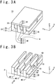
- FIG. 3A is a schematic perspective view showing a part of the cooling mechanism according to an example serving to explain features of the invention.
- FIG. 3B is a schematic perspective view showing the part of the cooling mechanism and is a diagram when an upper wall is omitted.
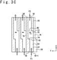
- FIG. 3C is a plan view of the part of the cooling mechanism shown in FIG. 3B and is a diagram when the upper wall is omitted.
- FIG. 4 is a graph schematically showing the temperature distribution of the bottom wall.
- FIG. 1 shows a rocket engine 1.
- the rocket engine 1 includes a combustor 2 and a nozzle 3.
- the combustor 2 includes a combustion chamber 4.
- FIG. 2A is a sectional view along the plane A of FIG. 1 .
- the combustor 2 includes a bottom wall 22 in contact with the combustion chamber 4, an upper wall 30 and a plurality of side walls 26. Each of the side walls 26 is connected with the upper wall 30 and the bottom wall 22.
- the bottom wall 22 and the plurality of side walls 26 are formed as a unitary body, and configures a first member 20 from the bottom wall 22 and the plurality of side walls 26.
- the upper wall 30 configure a second member formed separately from the first member.
- the first member 20 and the second member are bonded by a welding method, a brazing method and so on.
- the configuration of the bottom wall, the side walls, and the upper wall is not limited to an example of FIG. 2A .
- each of the bottom wall, the side wall, and the upper wall may be separately formed.
- the bottom wall 22 (or the bottom wall 22 and the side wall 26) is sometimes called an inner wall
- the upper wall 30 is sometimes called an outer wall.
- the space surrounded by the bottom wall 22, the upper wall 30 and the two side walls 26 configures a cooling passage 40, through which a cooling medium flows and passes.
- a cooling passage 40 through which a cooling medium flows and passes.
- FIG. 2A an example in which a plurality of cooling passages 40 are provided is shown.
- the number of cooling passages 40 is an optional integer equal to or more than one.
- the cooling medium is, for example, liquid-hydrogen.
- a kind of cooling medium is not limited to the liquid-hydrogen and is optional.
- the cooling medium may be liquid, may be gas and may be supercritical fluid.
- the materials of the bottom wall, the upper wall, and the side wall are optional.
- the materials of the bottom wall, the upper wall, and the side walls are, for example, copper alloy.
- FIG. 2B shows a modification example of the combustor.
- the combustor 2' is different from the combustor 2 shown in FIG. 2A in that a wall 21 surrounding the combustion chamber 4 is provided as a member separate from the bottom wall 22.
- the wall 21 and the bottom wall 22 are separately formed, and the wall 21 and the bottom wall 22 are bonded by a welding method, a brazing method and so on.
- a combination of the wall 21 and the bottom wall 22 is called the bottom wall.
- the cooling mechanism is applied to the combustion chamber of the rocket engine has been described in FIG. 1 to FIG. 2B .
- the object to which the cooling mechanism is applied is not limited to the example of FIG. 1 to FIG. 2B and is optional.
- the object to which the cooling mechanism is applied is an optional target in which cooling is needed.
- FIG. 3A is a schematic perspective view showing a part of the cooling mechanism.
- FIG. 3A shows an example of the cooling mechanism.
- the cooling mechanism 10 has a plurality of cooling passages 40 that include a first cooling passage 40-1, a second cooling passage 40-2, and a third cooling passage 40-3. Note that the cooling passages other than the first cooling passage 40-1, the second cooling passage 40-2, and the third cooling passage 40-3 are omitted in FIG. 3A , to avoid the complication of the drawing.
- first cooling passages 40-1, the second cooling passages 40-2, and the third cooling passages 40-3 is arranged between the bottom wall 22 and the upper wall 30.
- first cooling passage 40-1 is a passage surrounded by the bottom wall 22, the upper wall 30 and the two side walls 26 (note that one of the side walls is omitted).
- second cooling passage 40-2 is a passage surrounded by the bottom wall 22, the upper wall 30 and the two side walls 26.
- third cooling passage 40-3 is s passage surrounded with the bottom wall 22, the upper wall 30 and the two side walls 26.
- the bottom wall 22 is in contact with the combustion chamber 4. In other words, the bottom surface of the bottom wall faces directly to a combustion space as the combustion chamber 4.
- FIG. 3A an example will be described in which the first member 20 configuring first cooling passage 40-1, the first member 20 configuring the second cooling passage 40-2, and the first member 20 configuring the third cooling passage 40-3 are separately formed, and bonded to each other.
- the example is not limited to the example of FIG. 3A .
- the first member 20 configuring the first cooling passage 40-1, the first member 20 configuring the second cooling passage 40-2, and the first member 20 configuring the third cooling passage 40-3 may be formed from a single member as a unitary body.
- FIG. 3A an example in which the cross section of each cooling passage 40 perpendicular to the X axis is rectangular will be described. However, the cross section shape of each cooling passage 40 is optional.
- FIG. 3B is a schematic perspective view showing the part of the cooling mechanism, and is a diagram in which the upper wall 30 is removed from the configuration of FIG. 3A .
- the first cooling passage 40-1 wills be described.
- the first cooling passage 40-1 is a cooling passage arranged between the bottom wall 22 in contact with the combustion chamber 4 and the upper wall (not shown in FIG. 3B ).
- the first cooling passage 40-1 has a first passage 50 which is arranged along the bottom wall 22 to extend along the +X direction (in other words, the first direction). Also, the first cooling passage 40-1 has a second passage 60 which is arranged along the bottom wall 22 to extend to the +X direction (in other words, the first direction). The second passage 60 is arranged to have an offset to the first passage 50 in the direction along the Y axis (i.e. the second direction). Note that when the shape of the combustion chamber 4 is cylindrical, the direction along the Y axis is a direction along the circumference of the circular cylinder.
- the first cooling passage 40-1 has a connection section 70 (a first connection section 70) which is arranged between the first passage 50 and the second passage 60 in the direction along the X axis.
- the connection section 70 can be called a connection passage.
- the connection section 70 is connected with the first passage 50 and the second passage 60.
- the first passage 50 is connected with a side of the connection section 70 in the -X direction (the direction opposite to the first direction).
- the second passage 60 is connected with a side of the connection section 70 in the +X direction (the first direction).
- a first collision wall 72 is disposed to collide with a part of the cooling medium which flows through the connection section 70 to the +X direction (the first direction).
- a second collision wall 74 is arranged to collide with a part of the cooling medium which flows through the connection section 70 to the -X direction (a direction opposite to the first direction).
- the cooling medium which flows through the first passage 50 to the +X direction flows into the connection section 70 from the side of the connection section 70 in the -X direction.
- a part of the cooling medium which flows into the connection section 70 and flows through the connection section 70 to the +X direction collides with the first collision wall 72.
- a momentum component is given to the cooling medium through the collision to proceed toward directions except for the +X direction, and the cooling medium is stirred.
- the momentum component to proceed toward one direction except for the X direction is typically a momentum component T1 in the direction along the Y axis (i.e., the momentum component along the second direction), a momentum component in the direction along the Z axis, or a momentum component to proceed to the -X direction.
- FIG. 3B An example in which a flow direction of combustion gas G in the combustion chamber 4 is in the +X direction is shown in FIG. 3B .
- the flow direction of combustion gas G is not limited to the example of FIG. 3B and is optional.
- FIG. 3C is a plan view of a part of the cooling mechanism shown in FIG. 3B , and is a diagram when the upper wall is omitted. Note that in FIG. 3C , the side wall of the first cooling passage 40-1 in the -Y direction is shown by a broken line.
- the first passage 50 is a passage surrounded by a first side wall 56, a second side wall 58, the bottom wall 22 and the upper wall (not shown in FIG. 3C ).
- the connection section 70 (the connection passage) is a portion surrounded by a first side wall 76, a second side wall 78, the bottom wall 22, the upper wall (not shown in FIG. 3C ), a first boundary surface section B1 (a boundary surface section between the first passage 50 and the connection section 70), a second boundary surface section B2 (a boundary surface section between the connection section 70 and the second passage 60), the first collision wall 72 and the second collision wall 74.
- the second passage 60 is a passage surrounded by a first side wall 66, a second side wall 68, the bottom wall 22 and the upper wall (not shown in FIG. 3C ). Note that in the example shown in FIG. 3C , an area hatched by a slanted line shows an area where the side wall exists.
- the cooling medium F1 which flows through the first passage 50 flows into the connection section 70 through the first boundary surface section B1 between the first passage 50 and the connection section 70.
- a momentum component T1 in a direction along +Y direction and a momentum component in the direction along the Z axis are given by the first collision wall 72 to the cooling medium which flows through the connection section 70.
- the cooling medium which flows through the connection section 70 flows into the second passage 60 through the second boundary surface section B2 between the connection section 70 and the second passage 60.
- the cooling medium F2 which flows through the second passage 60 becomes large in the degree of turbulence by passing through the connection section 70, compared with the cooling medium F1 which flows through the side of the first passage 50 to the +X direction.
- FIG. 4 is a graph schematically showing a temperature distribution of the bottom wall.
- the x-axis of FIG. 4 shows a position of the bottom wall 22 along the +X direction (the unit: meter).
- the y-axis of FIG. 4 shows temperature of the bottom wall 22 (the unit: Kelvin).
- a curve shown by "B” shows a temperature change of the bottom wall when the cooling mechanism according to the embodiment is adopted, and a curve shown by "C” shows a temperature change of the bottom wall when the first passage and the second passage are not arranged to have an offset.
- the cooling medium which flows through the first passage 50 is gradually heated with the heat transferred from the combustion chamber. For this reason, when the cooling medium advances toward the downstream of the first passage 50 (to the +X direction), the cooling effect by the cooling medium declines gradually. As a result, the temperature of the bottom wall of the first passage 50 rises gradually from the upstream of the first passage 50 (the -X direction) to the downstream (the -X direction) (reference to the temperature change of the first passage 50, i.e., a part of the curve "B" corresponding to the first passage 50).
- connection section 70 the cooling medium is stirred since a part of the cooling medium collides with the first collision wall 72. Therefore, a part of the cooling medium having relatively higher temperature moves to leave from the bottom wall (the +Z direction), and a part of the cooling medium having relatively lower temperature moves to the direction approaching the bottom wall (the -Z direction).
- the temperature of the bottom wall of the connection section 70 lower than the temperature of the bottom wall on the downstream side of the first passage 50 (a part on the +X direction) (reference to the temperature change of the connection section 70, i.e. a part of the curve "B" corresponding to the connection section 70).
- the cooling medium which flows through the second passage 60 is gradually heated with the heat transferred from the combustion chamber. Therefore, as the cooling medium advances toward the downstream of the second passage 60 (the +X direction), the cooling effect by the cooling medium declines gradually. As a result, the temperature of the bottom wall in the second passage 60 rises gradually from the upstream of the second passage 60 (the -X direction) to the downstream thereof (the +X direction). The temperature of the bottom wall in the upstream of the second passage 60 (-the X direction) is kept relatively low by the stirring effect of the cooling medium in the connection section 70.
- the temperature of the bottom wall in the second passage 60 when the cooling mechanism according to the embodiment is adopted (reference to a part of the curve "B" corresponding to the second passage 60) becomes lower than the temperature of the bottom wall in the second passage 60 when the first passage and the second passage are not arranged to have an offset (reference to a part of the curve "C" corresponding to the second passage 60). Therefore, when the cooling mechanism according to embodiment is adopted, the cooling efficiency of the bottom wall by the cooling mechanism is improved.
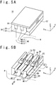
- FIG. 5A is a schematic perspective view showing a part of the cooling mechanism.
- FIG. 5B is a schematic perspective view showing a part of the cooling mechanism and is a diagram when the upper wall is omitted.
- FIG. 5C is a plan view of the part of the cooling mechanism shown in FIG. 5B , and is a diagram when the upper wall is omitted.
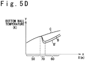
- FIG. 5D is a graph schematically showing a temperature distribution of the bottom wall.
- FIG. 5E is a diagram showing an offset distance.
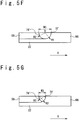
- FIG. 5F and FIG. 5G are diagrams showing the distance along the X direction between the first collision wall and the second collision wall.
- FIG. 5A is a schematic perspective view showing a part of the cooling mechanism.
- the cooling mechanism 10 has a plurality of cooling passages 40 which include the first cooling passage 40-1, the second cooling passage 40-2, and the third cooling passage 40-3.
- cooling passages except for the first cooling passage 40-1, the second cooling passage 40-2, and the third cooling passage 40-3 are omitted to avoid the complication of the drawing. That is, actually, a cooling passage is provided through the side wall in the -Y direction of the first cooling passage 40-1, a cooling passage is provided in the +Y direction through the side wall of the third cooling passage 40-3. However, these passages are omitted.
- first cooling passages 40-1, the second cooling passages 40-2, and the third cooling passages 40-3 is arranged between the bottom wall 22 and the upper wall 30.
- first cooling passage 40-1 is a passage surrounded by the bottom wall 22, the upper wall 30 and the two side walls 26 (note that one of the side walls is omitted).
- second cooling passage 40-2 is a passage surrounded by the bottom wall 22, the upper wall 30 and the two side walls 26.
- third cooling passage 40-3 is a passage surrounded by the bottom wall 22, the upper wall 30 and the two side walls 26.
- the bottom wall 22 is in contact with the combustion chamber 4. In other words, the bottom surface of the bottom wall faces directly to a combustion space as the combustion chamber 4. Note that in FIG.
- the bottom surface of the bottom wall 22 has a shape corresponding to the shape of the combustion chamber 4.
- the bottom surface of the bottom wall 22 has a curved surface corresponding to the side surface of the cylindrical shape.
- FIG. 5A shows an example in which the bottom wall 22 and the plurality of side walls 26 are formed from one member.
- the embodiment is not limited to such an example.
- the bottom wall 22 may be divided into a plurality of parts.
- the shape of a first collision wall 72' is different from the shape of the first collision wall in FIG. 3A .
- FIG. 5B is a schematic perspective view showing a part of the cooling mechanism, and is a diagram when the upper wall is omitted 30 shown in FIG. 5A .
- An example in which the shape of the first cooling passage 40-1, the shape of the second cooling passage 40-2 and the shape of the third cooling passage 40-3 are identical is shown in FIG. 5B .
- the second cooling passage 40-2 when being virtually translated in parallel to the -Y direction coincides with the first cooling passage 40-1.
- the third cooling passage 40-3 when being virtually translated in parallel to the -Y direction coincides with the first cooling passage 40-1. Therefore, only the first cooling passage 40-1 will be described.
- the first cooling passage 40-1 is a cooling passage arranged between the bottom wall 22 which is in contact with the combustion chamber 4, and the upper wall (not shown in FIG. 5B ).
- the first cooling passage 40-1 has the first passage 50 arranged along the bottom wall 22 to extend to the +X direction (in other words, the first direction). Also, the first cooling passage 40-1 has the second passage 60 arranged along the bottom wall 22 to extend to the +X direction (in other words, the first direction). The second passage 60 is arranged to have an offset in the direction along the Y axis to the first passage 50 (i.e. the second direction).
- the first cooling passage 40-1 has the connection section 70 arranged between the first passage 50 and the second passage 60 in the direction along the X axis.
- the connection section 70 can be referred to as the connection passage.
- the connection section 70 is connected with the first passage 50 and the second passage 60.
- the first passage 50 is connected with the side of the connection section 70 in the -X direction (in the direction opposite to the first direction).
- the second passage 60 is connected with a side of the connection section 70 in the +X direction (the first direction).
- a first collision wall 72' is arranged to collide with a part of the cooling medium which flows through the connection section 70 to the +X direction (the first direction).
- a second collision wall 74' is arranged to collide with a part of the cooling medium which flows through the connection section 70 to the - X direction (the direction opposite to the first direction).
- the first collision wall 72' has a surface far from the bottom wall 22 as proceeding for the +X direction (the first direction).
- the first collision wall 72' has a curved surface (the surface of an arc shape as an example). That is, the cross section of the first collision wall 72' along a plane perpendicular to the Y axis (in other words, the cross section perpendicular to the second direction) has a curved line.
- the second collision wall 74' has a surface becoming near the bottom wall 22 as heading for the +X direction (the first direction).
- the second collision wall 74' has a curved surface (an arc-shaped surface as an example). That is, the cross section of the second collision wall 74' along a plane perpendicular to the Y axis (in other words, the cross section perpendicular to the second direction) has a curved line.
- the shape of the second collision wall is identical to the shape of the first collision wall.
- the shape of the second collision wall may be different from the shape of the first collision wall.
- the shape of the second collision wall the shape of the second collision wall 74 shown in FIG. 3B may be adopted, the shape of a second collision wall 74'' shown in FIG. 6A may be adopted, or another shape may be adopted.
- the cooling medium which flows through the first passage 50 to the +X direction flows into the connection section 70 from the side of the connection section 70 in the -X direction.
- a part of the cooling medium which flows into the connection section 70 and flows through the connection section 70 to the +X direction collides with the first collision wall 72'.
- a momentum component is given to the cooling medium through the collision to advance toward the directions except for the +X direction, and the cooling medium is stirred.
- the momentum component proceeding toward the direction except for the X direction is typically a momentum component along the Y axis (i.e., the momentum component of the second direction), and also, is the momentum component proceeding toward the +Z direction.
- the momentum component in the +Z direction which is generated by collision of the cooling medium with the first collision wall 72' generates a rotary flow RT rotating around the Y axis in the connection section 70.
- the cooling medium with a higher temperature which flows through a region near the bottom wall 22 moves to a direction apart from the bottom wall 22 by the rotary flow RT, and the cooling medium with a lower temperature which flows through the region far from the bottom wall 22 moves to the direction approaching the bottom wall 22.
- the connection section 70 the temperature inclination of the cooling medium in a direction of the Z axial is effectively eased.
- the cooling medium in which the temperature inclination has been effectively eased in the connection section 70 flows into the second passage 60. Almost of the cooling medium F2 which flows through the second passage 60 moves to the +X direction. Note that the cooling medium F2 flowing through the second passage 60 after passing through the connection section 70 has a large degree of turbulence, compared with the cooling medium F1 which flows to the +X direction in the first passage 50.
- the first collision wall 72' becomes far from the bottom wall 22 as proceeding for the +X direction (the first direction). Therefore, the rotary flow RT is effectively generated.
- the second collision wall 74' becomes near the bottom wall 22 as proceeding for the +X direction (the first direction). Therefore, the rotary flow RT is effectively maintained.
- the flow direction of combustion gas G in the combustion chamber 4 is the +X direction.
- the flow direction of combustion gas G is not limited to the example of FIG. 5B and is optional.
- FIG. 5C is a plan view of a part of the cooling mechanism shown in FIG. 5B , and is a diagram when the upper wall is omitted. Note that the side wall of the first cooling passage 40-1 in the -Y direction is shown by the broken line in FIG. 5C (that is, the side wall omitted in FIG. 5B ).
- the first passage 50 is a passage surrounded by the first side wall 56, the second side wall 58, the bottom wall 22 and the upper wall (not shown in FIG. 5C ).
- the connection section 70 (the connection passage) is a part surrounded by the first side wall 76, the second side wall 78, the bottom wall 22, the upper wall (not shown in FIG. 5C ), a first boundary surface section B1, a second boundary surface section B2, the first collision wall 72' and the second collision wall 74'.
- the second passage 60 is a passage surrounded by the first side wall 66, the second side wall 68, the bottom wall 22 and the upper wall (not shown in FIG. 5C ). Note that in the example of FIG. 5C , a region hatched by slanted lines shows a region where the side wall exists, and the region where the cooling medium does not exist.
- the cooling medium F1 which flows through the first passage 50 flows into the connection section 70 through the first boundary surface section B1 between the first passage 50 and the connection section 70.
- a momentum component T1 for the +Y direction and a momentum component for the +Z direction are given to the cooling medium, which flows through the connection section 70, by the first collision wall 72'. Due to the rotary flow RT caused by the collision with the first collision wall 72', a part of the cooling medium collides with the second collision wall 74'. The rotary flow RT is effectively maintained by the second collision wall 74'.
- the cooling medium which flows through the connection section 70 flows into the second passage 60 through the second boundary surface section B2 between the connection section 70 and the second passage 60.
- FIG. 5D is a graph schematically showing a temperature distribution of the bottom wall.
- the x-axis of FIG. 5D shows the position of the bottom wall 22 along the +X direction (unit: meter).
- the y axis of FIG. 5D shows the temperature (unit: Kelvin) of the bottom wall 22.
- a curve shown by "B” shows a temperature change of the bottom wall when the cooling mechanism of the embodiments shown in FIG. 3A to FIG. 3C is adopted.
- a curve shown by "B'” shows a temperature change of the bottom wall when the cooling mechanism of the embodiment shown in FIG. 5A to FIG. 5C is adopted.
- a curve specified by "C” shows a temperature change of the bottom wall when the first passage and the second passage are not arranged to have an offset.
- the rotary flow RT is effectively caused in the connection section 70. Therefore, in the example of FIG. 5A to FIG. 5C , the cooling efficiency of the bottom wall by the cooling mechanism is more improved, compared with the embodiment shown in FIG. 3A to FIG. 3C .
- FIG. 5E is a plan view of a part of the cooling mechanism shown in FIG. 5B and is a diagram when the upper wall is omitted.
- a longitudinal center axis of the first passage 50 is defined as a central axis C1
- a longitudinal center axis of the second passage 60 is defined as a central axis C2.
- a distance between the central axis C1 and the central axis C2 is an offset distance OF.
- the distance between the longitudinal center axis C1 of the first passage 50 and the longitudinal center axis C2 of the second passage 60 in a second direction (the direction along the Y axis) which is perpendicular to the +X direction (the first direction) and along the bottom wall 22 can be defined as an offset distance OF.
- the offset distance OF is, for example, smaller than the width W1 of the first passage 50 in the direction along the Y axis (the second direction).
- a part of the first passage 50 overlaps with a part of the second passage 60 when viewing to the +X direction.
- a part of the cooling medium which flows through the first passage 50 to the +X direction proceeds to the +X direction through the connection section 70 without colliding with the first collision wall 72', and is possible to flow into the second passage 60.
- the decline of the flow speed of the cooling medium due to existence of the connection section 70 or the pressure loss of the cooling medium is reduced.
- the decline of flow speed of the cooling medium causes the decline of the heat transfer coefficient of the cooling medium.
- the offset distance OF is smaller than the width W1
- the decline of flow speed of the cooling medium is restrained and the decline of the heat transfer coefficient of the cooling medium is restrained.
- the cooling efficiency by the cooling mechanism is more improved.
- width W2 of the second passage 60 in the direction along the Y axis (the second direction) is, for example, equal to the width W1 of the first passage.
- FIG. 5F and FIG. 5G are diagrams showing the distance in the X direction between the first collision wall 72' and the second collision wall 74'.
- the radius of curvature of the first collision wall 72' is defined as radius R1
- the radius of curvature of the second collision wall 74' is defined as radius R2.
- the radius R1 and the radius R2 coincide with each other.
- the central axis O of an arc surface of the first collision wall 72' and the central axis O of an arc surface of the second collision wall 74' coincide with each other. Therefore, in the example of FIG. 5F , the rotary flow RT is effectively generated and is maintained.
- a distance W3 between the upper end of the first collision wall 72' and the upper end of the second collision wall 74' is equal to a summation of the radius R1 and the radius R2 (in other words, the distance W3 between the upper end of the first collision wall 72' and the upper end of the second collision wall 74' is equal to twice of the radius R1).
- the area of cross section of the connection section 70 perpendicular to the X axis is larger than the area of cross section of the first passage 50 perpendicular to the X axis.
- the cross section area of the passage becomes large, the flow speed declines. Therefore, the flow speed of the cooling medium in the connection section 70 is smaller than the flow speed of the cooling medium of the first passage 50. According to the decline of the flow speed, there is a fear that cooling efficiency of the bottom wall 22 in the connection section 70 declines.
- FIG. 5G An example of means for restraining the decline of flow speed of the cooling medium in the connection section 70 is shown in FIG. 5G .
- the distance W3 between the upper end of the first collision wall 72' and the upper end of the second collision wall 74' is smaller than a summation of the radius R1 and the radius R2 (in other words, the distance W3 between the upper end of the first collision wall 72' and the upper end of the second collision wall 74' is smaller than twice of the radius R1).
- the position of the lower end of the second collision wall 74' in the direction along the X axis is in the +X direction (the first direction), compared with the position of the lower end of the first collision wall 72' in the direction along the X axis. That is, when viewing the first collision wall 72' and the second collision wall 74' in the direction along the Y axis, the first collision wall 72' and the second collision wall 74' intersect each other. Therefore, the maximum value of the area of cross section, perpendicular to the X axis, of the connection section 70 shown in FIG. 5G is smaller than the maximum value of the area of cross section, perpendicular to the X axis, of the connection section 70 shown in FIG. 5F . As a result, in the example shown in FIG. 5G , the decline of flow speed of the cooling medium in the connection section 70 is restrained.
- the distance W3 between the upper end of the first collision wall 72' and the upper end of the second collision wall 74' is equal to the length of the connection section 70 in the +X direction (the first direction).
- FIG. 6A to FIG. 6C a second modification example of the collision wall will be described.
- the shape of a first collision wall 72'' and the shape of a second collision wall 74'' are different from those of the examples of FIG. 5A to FIG. 5G .
- the other components in the example shown in FIG. 6A to FIG. 6C are same as those in the example shown in FIG. 5A to FIG. 5G .
- FIG. 6A is a schematic perspective view showing a part of the cooling mechanism and is a diagram when the upper wall is omitted.
- FIG. 6B is a side view of the part of the cooling mechanism shown in FIG. 6A and a diagram when the upper wall is omitted.
- the first collision wall 72'' has a surface far from the bottom wall 22 as proceeding for the +X direction (the first direction). In more detail, the first collision wall 72'' has an even slope.
- the second collision wall 74'' has a surface approaching the bottom wall 22 as proceeding for the +X direction (the first direction). In more detail, the second collision wall 74'' has an even slope.
- the shape of the second collision wall is identical to the shape of the first collision wall. However, the embodiment is not limited to such an example. The shape of the second collision wall may be different from the shape of the first collision wall. As the shape of the second collision wall, the shape of the second collision wall 74 shown in FIG. 3B may be adopted, the shape of the second collision wall 74' shown in FIG. 5B may be adopted, or another shape may be adopted.
- the rotary flow RT is effectively caused by the first collision wall 72'' in FIG. 6A and FIG. 6B . Also, the rotary flow RT is effectively maintained by the second collision wall 74'' in FIG. 6A and FIG. 6B . Therefore, in the example of FIG. 6A and FIG. 6B , the cooling efficiency by the cooling mechanism is more improved, compared with the example shown in FIG. 3A to FIG. 3C .
- FIG. 6B and FIG. 6C are diagrams showing the distance in the X direction between the first collision wall and the second collision wall.
- the position of the lower end of the first collision wall 72'' in the direction along the X axis is equal to the position of the lower end of the second collision wall 74'' in the direction along the X axis.
- the area of cross section of the connection section 70 perpendicular to the X axis is larger than the area of cross section of the first passage 50 perpendicular to the X axis.
- FIG. 6C An example of means for restraining the decline of flow speed of the cooling medium in the connection section 70 is shown in FIG. 6C .
- the position of the lower end of the second collision wall 74'' in the direction along the X axis is in the +X direction (the side of the first direction), compared with the position of the lower end of the first collision wall 72'' in the direction along the X axis.
- the first collision wall 72'' and the second collision wall 74'' intersect each other.
- the maximum value of the area of cross section, perpendicular to the X axis, of the connection section 70 shown in FIG. 6C is smaller than the maximum value of the area of cross section, perpendicular to the X axis, of the connection section 70 shown in FIG. 6B .
- the decline of flow speed of the cooling medium in the connection section 70 is restrained.
- the distance W3 between the upper end of the first collision wall 72'' and the upper end of the second collision wall 74'' is equal to the length of the connection section 70 in the +X direction (the first direction).
- the distance W3 it is possible to equalize the area of cross section of the connection section 70 perpendicular to the X axis and the area of cross section of the first passage 50 perpendicular to the X axis.
- the distance W3 it is possible to equalize the area of cross section of the connection section 70 perpendicular to the X axis and the area of cross section of the second passage 60 perpendicular to the X axis.
- connection section 70 perpendicular to the X axis and the area of cross section of the first passage 50 perpendicular to the X axis are equal to each other, the decline of flow speed of the cooling medium in the connection section 70 is most restrained.
- FIG. 7A and FIG. 7B a third modification example of the collision wall will be described.
- the shape of a first collision wall 72''' is different from that of the example shown in FIG. 6A to FIG. 6C .
- the other components in the example shown in FIG. 7A and FIG. 7B are same as those of the example shown in FIG. 6A to FIG. 6C .
- FIG. 7A is a schematic perspective view showing a part of the cooling mechanism and is a diagram when the upper wall is omitted.
- FIG. 7B is a side view of the part of the cooling mechanism shown in FIG. 7A and is a diagram when the upper wall is omitted.
- the first collision wall 72''' has a step-like surface far from the bottom wall 22 as proceeding for the +X direction (the first direction).
- the shape of a second collision wall 74''' in the example shown in FIG. 7B is identical to the shape of the second collision wall 74" in the example shown in FIG. 6B .
- the shape of the second collision wall may be identical to the shape of the first collision wall 72'''.
- the shape of the second collision wall the shape of the second collision wall 74 shown in FIG. 3B may be adopted, or the shape of the second collision wall 74' shown in FIG. 5B may be adopted.
- the rotary flow RT is effectively caused by the first collision wall 72'''. Also, the rotary flow RT is effectively maintained by the second collision wall 74'''. Therefore, in the example shown in FIG. 7A and FIG. 7B , the cooling efficiency by the cooling mechanism is improved.
- FIG. 8A is a plan view of a part of the cooling mechanism and is a diagram when the upper wall is omitted.
- the first passage 50 and the second passage 60 in FIG. 8A may be identical to any of the first passage 50 and the second passage 60 shown in FIG. 3A to FIG. 3C , the first passage 50 and the second passage 60 shown in FIG. 5A to FIG. 5G , the first passage 50 and the second passage 60 shown FIG. 6A to FIG. 6C , and the first passage 50 and the second passage 60 shown in FIG. 7 and FIG. 7B .
- the cooling mechanism 10 has a plurality of cooling passages 40 which contain the first cooling passage 40-1, the second cooling passage 40-2, and the third cooling passage 40-3.
- cooling passages except for the first cooling passage 40-1, the second cooling passage 40-2, and the third cooling passage 40-3 are omitted to avoid the complication of the drawing. That is, actually, a cooling passage is provided in the -Y direction of the first cooling passage 40-1 through the side wall. A cooling passage is provided in the +Y direction of the third cooling passage 40-3 through the side wall. However, these passages are omitted in the drawing.
- Each of the first cooling passages 40-1, the second cooling passages 40-2, and the third cooling passages 40-3 is arranged between the bottom wall 22 and the upper wall 30 (not shown in FIG. 8A ).
- the first cooling passage 40-1 is a cooling passage surrounded by the bottom wall 22 in contact with the combustion chamber 4, the upper wall (not shown in FIG. 8A ) and the two side walls.
- the first passage 50 and the second passage 60 are same as the first passage 50 and the second passage 60 shown in FIG. 3A to FIG. 7B . Therefore, the description is omitted.
- a second connection section 90 and a third passage 80 are mainly described.
- the first cooling passage 40-1 includes the third passage 80 arranged along the bottom wall 22 to extend along the +X direction (in other words, the first direction).
- the third passage 80 is arranged to have an offset in the direction along the Y axis (i.e. the second direction) to the second passage 60.
- the third passage 80 is a passage which is surrounded by a first side wall 86, a second side wall 88, the bottom wall 22 and the upper wall (not shown in FIG. 8A ).
- the first cooling passage 40-1 has a second connection section 90 arranged between the second passage 60 and the third passage 80 in the direction along the X axis.
- the second connection section 90 can be also called a second connection passage.
- the second connection section 90 is connected with the second passage 60 and is connected with the third passage 80.
- the second passage 60 is connected with the side of the second connection section 90 in the -X direction (the direction opposite to the first direction).
- the third passage 80 is connected with a part of the second connection section 90 in the +X direction (the first direction).
- the second connection section 90 (the second connection passage) is a part surrounded by a first side wall 96, a second side wall 98, the bottom wall 22, the upper wall (not shown in FIG. 8A ), a third boundary surface section B3, a fourth boundary surface section B4, a third collision wall 92 and a fourth collision wall 94.
- the third collision wall 92 is arranged in the end of the second connection section 90 in the +X direction (the first direction) such that a part of the cooling medium which flows through the second connection section 90 to the +X direction (the first direction) collides with the third collision wall 92.
- the fourth collision wall 94 is arranged in the end of the second connection section 90 in the -X direction (the direction opposite to the first direction) such that a part of the cooling medium which flows through the second connection section 90 to the -X direction (the direction opposite to the first direction) collides with the fourth collision wall 94.
- the shape of the third collision wall 92 may be identical to the shape of the first collision wall 72 shown in FIG. 3B , may be identical to the shape of the first collision wall 72' shown in FIG. 5B , may be identical to the shape of the first collision wall 72'' shown in FIG. 6A , or may be another shape.
- the shape of the fourth collision wall 94 may be identical to the shape of the second collision wall 74 shown in FIG. 3B , may be identical to the shape of the second collision wall 74' shown in FIG. 5B , may be identical to the shape of the second collision wall 74'' shown in FIG. 6A , or may be another shape.
- the cooling medium F2 which flows through the second passage 60 to the +X direction flows into the second connection section 90 from the end of the second connection section 90 in the -X direction (the third boundary surface section B3).
- a part of the cooling medium which flows into the second connection section 90 and flows through the second connection section 90 to the +X direction collides with the third collision wall 92.
- a momentum component which heads for a direction except for the +X direction is given to the cooling medium by the collision, and the cooling medium is stirred.
- a momentum component which heads for a direction except for the X direction is typically a momentum component in the direction along the Y axis (i.e. the second direction), and a momentum component in the direction along the Z axis.
- the stirred cooling medium flows into the third passage 80 through the fourth boundary surface section B4.
- the cooling medium F3 which flows into the third passage flows through the third passage 80 to the +X direction.
- the cooling medium F3 which flows through the third passage is the cooling medium effectively stirred in the second connection section. Therefore, the cooling efficiency of the bottom wall in the third passage 80 is improved.
- a length W4 in the direction along the X axis between the connection section 70 and the second connection section 90 is determined in consideration of a degree of the temperature inclination in the direction along the Z axis, of the cooling medium which flows through the second passage 60.
- FIG. 8B is a graph schematically showing a temperature distribution of the bottom wall.
- the x-axis of FIG. 8B shows a position (the unit: meter) of the bottom wall 22 along the +X direction.
- the Y axis of FIG. 8B shows the temperature of the bottom wall 22 (the unit: Kelvin).
- a curve shown by "B” shows a temperature change of the bottom wall when the cooling mechanism in the embodiment shown in FIG. 8A is adopted.
- a curve shown by "C” shows the temperature change of the bottom wall when the first passage and the second passage are not arranged to have an offset and when the second passage and the third passage are not arranged to have an offset.
- connection section 70 and the second connection section 90 are effectively stirred in the connection section 70 and the second connection section 90 so that the cooling efficiency of the bottom wall is improved.
- FIG. 8A an example in which the second passage 60 is arranged to have an offset in the +Y direction to the first passage 50, and the third passage 80 is arranged to have an offset in the -Y direction to the second passage 60 is shown in FIG. 8A . That is, in the example of FIG. 8A , the direction of the offset of the second passage 60 to the first passage 50 is opposite to the direction of the offset of the third passage 80 to the second passage 60.
- FIG. 9 an example in is shown in FIG. 9 which the second passage 60 is arranged to have an offset in the +Y direction to the first passage 50 and the third passage 80 is arranged to have an offset in the +Y direction to the second passage 60. That is, the direction of the offset of the second passage 60 to the first passage 50 is the same as the direction of the offset of the third passage 80 to the second passage 60 in the example of FIG. 9 .
- the cooling efficiency of the bottom wall is improved, like the embodiment shown in FIG. 8A .
- FIG. 10 is a plan view of a part of the cooling mechanism and is a diagram when the upper wall is omitted.
- the cooling mechanism 10 has a plurality of cooling passages 40 which contain the first cooling passage 40-1, the second cooling passage 40-2, and the third cooling passage 40-3. Note that the cooling passages except for the first cooling passage 40-1, the second cooling passage 40-2, and the third cooling passage 40-3 are omitted in FIG. 10 to avoid the complication of the drawing.
- a cooling passage is provided on the side of the first cooling passage 40-1 in the -Y direction through the side wall, and a cooling passage is provided on the side of the +Y direction of the third cooling passage 40-3 through the side wall.
- these passages are omitted.
- the first cooling passage 40-1 includes a first connection section 70-1 and a second connection section 90-1.
- the second cooling passage 40-2 includes a third connection section 70-2 and a fourth connection section 90-2.
- the third cooling passage 40-3 includes a fifth connection section 70-3 and a sixth connection section 90-3.
- the first connection section 70-1 and the third connection section 70-2 are arranged to have an offset to each other in the direction along the X axis.
- the third connection section 70-2 and the fifth connection section 70-3 are arranged to have an offset to each other in the direction along the X axis.
- the second connection section 90-1 and the fourth connection section 90-2 are arranged to have an offset to each other in the direction along the X axis.
- the fourth connection section 90-2 and the sixth connection section 90-3 are arranged to have an offset to each other in the direction along the X axis.
- Each of the first connection section 70-1, the second connection section 90-1, the third connection section 70-2, the fourth connection section 90-2, the fifth connection section 70-3, and the sixth connection section 90-3 has a collision wall and is a region in which that the area of cross section perpendicular to the X axis is relatively large.
- each of the first connection section 70-1, the second connection section 90-1, the third connection section 70-2, the fourth connection section 90-2, the fifth connection section 70-3, and the sixth connection section 90-3 is a region where there is a possibility that flow speed of the cooling medium declines.
- the cooling effect becomes insufficient to the bottom wall of the first connection section 70-1, the bottom wall of the second connection section 90-1, the bottom wall of the third connection section 70-2, the bottom wall of the fourth connection section 90-2, the bottom wall of the fifth connection section 70-3, and the bottom wall of the sixth connection section 90-3.
- the plurality of connection sections are arranged to have offsets to each other in the direction along the X axis. Therefore, the region where there is a possibility that the cooling effect becomes insufficient is arranged distributedly in the X direction. Thus, the cooling of the whole bottom wall 22 becomes able to be more uniformly carried out.
- the first cooling passage 40-1 has a first passage 50-1, a first connection section 70-1, a second passage 60-1, a second connection section 90-1 and a third passage 80-1.
- the second passage 60-1 is arranged to have an offset in the +Y direction to the first passage 50-1.
- the third passage 80-1 is arranged to have an offset in the -Y direction to the second passage 60-1.
- the first connection section 70-1 has the first collision wall 72-1, the second collision wall 74-1, the first boundary surface section B1 (a boundary surface section between the first passage 50-1 and the first connection section 70-1), and the second boundary surface section B2 (a boundary surface section between the first connection section 70-1 and the second passage 60-1).
- the second connection section 90-1 has a first collision wall 92-1, a second collision wall 94-1, a third boundary surface section B3 (a boundary surface section between the second passage 60-1 and the second connection section 90-1), and a fourth boundary surface section B4 (a boundary surface section between the second connection section 90-1 and the third passage 80-1).
- the second cooling passage 40-2 has a fourth passage 50-2, the third connection section 70-2, a fifth passage 60-2, a fourth connection section 90-2 and a sixth passage 80-2.
- the fifth passage 60-2 is arranged to have an offset in the +Y direction to the fourth passage 50-2.
- the sixth passage 80-2 is arranged to have an offset in the -Y direction to the fifth passage 60-2.
- the third connection section 70-2 has a first collision wall 72-2, a second collision wall 74-2, a fifth boundary surface section B5 (a boundary surface section between fourth passage 50-2 and a third connection section 70-2) and a sixth boundary surface section B6 (a boundary surface section between the third connection section 70-2 and fifth passage 60-2).
- the fourth connection section 90-2 has a first collision wall 92-2, a second collision wall 94-2, a seventh boundary surface section B7 (a boundary surface section between the fifth passage 60-2 and the fourth connection section 90-2), and an eighth boundary surface section B8 (a boundary surface section between a fourth connection section 90-2 and a sixth passage 80-2).
- the third cooling passage 40-3 has a seventh passage 50-3, a fifth connection section 70-3, an eighth passage 60-3, a sixth connection section 90-3 and a ninth passage 80-3.
- the eighth passage 60-3 is arranged to have an offset in the +Y direction to the seventh passage 50-3.
- the ninth passage 80-3 is arranged to have an offset in the -Y direction to the eighth passage 60-3.
- the fifth connection section 70-3 has the first collision wall 72-3, the second collision wall 74-3, the ninth boundary surface section B9 (a boundary surface section between the seventh passage 50-3 and the fifth connection section 70-3), and a tenth boundary surface section B10 (a boundary surface section between the fifth connection section 70-3 and the eighth passage 60-3).
- the sixth connection section 90-3 has a first collision wall 92-3, a second collision wall 94-3, an eleventh boundary surface section B11 (a boundary surface section between the eighth passage 60-3 and the sixth connection section 90-3), and a twelfth boundary surface section B12 (a boundary surface section between the sixth connection section 90-3 and the ninth passage 80-3).
- each first collision wall may be identical to the shape of the first collision wall 72 shown in FIG. 3B , may be identical to the shape of the first collision wall 72' shown in FIG. 5B , may be identical to the shape of the first collision wall 72'' shown diagram 6A, or may be another shape.
- the shape of each second collision wall may be identical to the shape of the second collision wall 74 shown in FIG. 3B , may be identical to the shape of the second collision wall 74' shown in FIG. 5B , may be identical to the shape of the second collision wall 74'' shown diagram 6A, or may be another shape.
- FIG. 11 is a flow chart showing the manufacturing process of the cooling mechanism.
- the first member 20 is prepared to have a bottom surface 23 and an upper surface 25.
- FIG. 12 shows a schematic perspective view of the prepared first member 20. Note that the bottom surface 23 is a surface to be cooled or a surface in contact with a cooling target.
- the first step S1 is a step of preparing the first member 20.
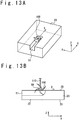
- FIG. 13A and FIG. 13B are a schematic perspective view and a schematic side view showing the state during execution of the second step S2. Note that in FIG. 13A (and FIG. 14A , FIG. 15, FIG. 16 , FIG. 17A ), a supporting member 110 which supports the rotary blade 100 to be rotatable is omitted.
- the first ditch 51 is formed in the first member 20 to extend to the +X direction (the first direction).
- the rotation axis RA of the rotary blade 100 is parallel to the Y axis.
- the movement of the rotary blade 100 to the +X direction (the first direction) is stopped. Since the movement of the rotary blade 100 to the +X direction is stopped, the first collision wall 72' is formed on the side of the first member 20 in the +X direction from the rotary blade 100. The first collision wall 72' is formed through cutting by the rotary blade 100.
- the first collision wall 72' has the surface of an arc shape, and the radius of the arc is equal to the rotation radius of the rotary blade 100 (that is, a distance from the rotation axis RA of the rotary blade 100 to the tip of the rotary blade). Note that the first collision wall 72' is shown in FIG. 14B . Also, the first collision wall 72' has a surface which is far from the bottom surface 23 as proceeding for the +X direction (the first direction). Note that the step of forming the first collision wall 72' is included in a step of forming the first connection section 70.
- the first connection section 70 is a region which connects the first ditch 51 and a second ditch 61 to be described later, and is the region having the first collision wall 72' and the second collision wall 74' to be described later.
- the first connection section 70 (referring to FIG. 16 , FIG. 17A, and FIG. 17B , if necessary) may be identical to the first connection section 70 in the example shown in FIG. 5B and FIG. 5C .
- the first collision wall 72' is on the side of the first ditch 51 in the +X direction, and is formed in the end of the first connection section 70 in the +X direction.
- the second step S2 is a step of forming the first ditch 51.
- FIG. 14A and FIG. 14B are respectively a schematic perspective view and a schematic side view showing the state during execution of the third step S3.
- the third step S3 is a rotary blade rising step.
- FIG. 15 is a schematic perspective view showing the state during execution of the fourth step S4.
- the movement component in the direction along the X axis or the movement component in the direction along the Z axis may be contained in the above-mentioned offset movement. That is, the movement in the direction along the Y axis may be combined with the movement in a direction along the X axis or the movement in a direction along the Z axis.
- the distance W3 between the upper end of the first collision wall 72' and the upper end of the second collision wall 74' should be made smaller than twice the rotation radius of the rotary blade 100
- the fourth step S4 is an offset movement step.
- FIG. 16 is a schematic perspective view showing a state after execution of the fifth step S5.
- the second collision wall 74' is formed in the first member 20.
- the second collision wall 74' has a surface of an arc shape, and the radius of the arc is equal to the rotation radius of the rotary blade 100 (that is, a distance from the rotation axis RA of the rotary blade 100 to the tip of the rotary blade).
- the second collision wall 74' is a surface in which the distance from the bottom surface 23 becomes short as proceeding for the +X direction (the first direction).
- the fifth step is the rotary blade descending step. Note that the step of forming the second collision wall 74' is contained in the step of forming the first connection section 70.
- the second collision wall 74' is formed at the end of the first connection section 70 in the - X direction and the end of the second ditch 61 in the -X direction.
- FIG. 17A and FIG. 17B are respectively a schematic perspective view and a schematic side view showing the state during execution of the sixth step S6.
- the second ditch 61 is formed in the first member 20 to extend to the +X direction (the first direction). Note that the rotation axis RA of the rotary blade 100 is parallel to the Y axis.
- the second ditch 61 is arranged to have an offset in the +Y direction or the -Y direction to the first ditch 51.
- the sixth step S6 is a step of forming the second ditch 61.
- a seventh step S7 it is determined whether another offset ditch is to be formed. The determination may be carried out by a user and may be automatically carried out by a control device which controls the rotary blade 100.
- the third ditch is formed to have an offset in the +Y direction or the -Y direction to the second ditch 61.
- the process of the second half the above-mentioned second step S2 (the step of stopping the movement of the rotary blade 100 to the +X direction) to the sixth step S6 is repeatedly executed.
- step S7 when the offset ditches are determined not to be further form (in case of NO), the control advances to an eighth step S8.
- FIG. 18 is a schematic perspective view showing a state after execution of the eighth step S8. Note that the eighth step S8 may be incorporated into the sixth step S6 (in other words, the eighth step S8 may be omitted).
- FIG. 19 is a schematic perspective view showing a state after execution of the ninth step S9.
- the first ditch 51, the second ditch 61, and so on function as the passages through which the cooling medium passes.
- the first collision wall 72' functions as the surface which generates the rotary flow RT effectively.
- the second collision wall 74' functions as the surface which maintains the rotary flow RT effectively.
- the ninth step S9 is a bonding step of the first member 20 and the second member (the upper wall 30).
- the step of forming the first collision wall 72' is executed between the step of forming the first ditch 51 (S2) and the step of forming the second ditch 61 (S6).
- the first ditch 51 may be formed by moving the rotating rotary blade 100 along the -X direction after the rotating rotary blade 100 is descended to form the first collision wall 72'. That is, the step of forming the first collision wall 72' may be executed before the step of forming the first ditch 51 (S2) and after the step of forming the first ditch 51 (S2).
- the step of forming the first collision wall 72' may be executed before the step of forming the second ditch 61 (S6) and after the step of forming the second ditch 61 (S6).
- the step of forming the first collision wall 72' is executed before the step of forming the second collision wall 74'.
- the step of forming the first collision wall 72' may be executed after the step of forming the second collision wall 74'.
- the step of forming the second collision wall 74' is executed between the step of forming the first ditch 51 (S2) and the step of forming the second ditch 61 (S6).
- the second collision wall 74' may be formed by raising the rotary blade 100 after the second ditch 61 is formed by moving the rotating rotary blade 100 along the -X direction. That is, the step of forming the second collision wall 74' may be executed before the step of forming the second ditch 61 (S6) and may be executed after the step of forming the second ditch 61 (S6).
- the step of forming the second collision wall 74' may be executed before the step of forming the first ditch 51 (S2) and may be executed after the step of forming the first ditch 51 (S2).
- the first ditch 51 (the first passage) and the second ditch 61 (the second passage) having an offset to the first ditch in the direction along the Y axis can be formed by only combining the movement of the rotary blade 100 along the X axis, the movement of the rotary blade 100 along the Y axis and the movement of the rotary blade 100 along the Z axis.
- the first collision wall 72' and the second collision wall 74' can be formed by only combining the movement of the rotary blade 100 along the X axis, the movement of the rotary blade 100 along the Y axis and the movement of the rotary blade 100 along the Z axis. Therefore, the manufacture of the cooling mechanism with high cooling efficiency becomes able to be easily carried out.
Landscapes
- Engineering & Computer Science (AREA)
- Mechanical Engineering (AREA)
- General Engineering & Computer Science (AREA)
- Chemical & Material Sciences (AREA)
- Combustion & Propulsion (AREA)
- Turbine Rotor Nozzle Sealing (AREA)
- Gas Burners (AREA)
Claims (12)
- Ein Kühlmechanismus (10) einer Brennkammer (4), umfassend:eine Innenwand (22) in Kontakt mit der Brennkammer (4),eine Außenwand (30), undeinen Kühldurchgang (40), der zwischen der Innenwand (22) und der Außenwand (30) angeordnet ist,wobei der Kühldurchgang (40) umfasst:einen ersten Durchgang (50), der entlang der Innenwand (22) so angeordnet ist, dass er sich in einer ersten Richtung (X) erstreckt,einen zweiten Durchgang (60), der entlang der Innenwand (22) so angeordnet ist, dass er sich in der ersten Richtung (X) erstreckt, undeinen ersten Verbindungsabschnitt (70), der mit dem ersten Durchgang (50) und dem zweiten Durchgang (60) verbunden ist,wobei eine Längsmittelachse (C1) des ersten Durchgangs (50) und eine Längsmittelachse (C2) des zweiten Durchgangs (60) in einer zweiten Richtung (Y), die senkrecht zur ersten Richtung (X) ist und sich entlang der Innenwand (22) erstreckt, voneinander getrennt sind,wobei der erste Durchgang (50) mit einem Teil des ersten Verbindungsabschnitts (70) durch eine erste Kollisionswand (72';72'';72''') verbunden ist, die an einem Ende des ersten Verbindungsabschnitts (70) in der ersten Richtung (X) so angeordnet ist, dass ein Teil eines Kühlmediums (F1), das im Betrieb durch den ersten Durchgang (50) in die erste Richtung (X) und in den ersten Verbindungsabschnitt (70) hinein strömt, mit der ersten Kollisionswand (72';72'';72'''') kollidiert,wobei der zweite Durchgang (60) mit einem Teil des ersten Verbindungsabschnitts (70) durch eine zweite Kollisionswand (74';74";74"') verbunden ist, die an einem Ende des ersten Verbindungsabschnitts (70) in der Richtung (-X) entgegengesetzt zu der ersten Richtung (X) angeordnet ist, so dass ein Teil des Kühlmediums (F1), das im Betrieb durch den ersten Verbindungsabschnitt (70) in die Richtung (-X) entgegengesetzt zu der ersten Richtung (X) strömt, mit der zweiten Kollisionswand (74';74";74''') kollidiert und weiter in dem zweiten Durchgang (60) in die erste Richtung (X) strömt,wobei die zweite Kollisionswand (74';74";74"') eine Oberfläche aufweist, die sich der Innenwand (22) im Verlauf in der ersten Richtung (X) nähert, undwobei die erste Kollisionswand (72';72";72"') eine Oberfläche aufweist, die sich von der Innenwand (22) im Verlauf in der erste Richtung (X) entfernt.
- Der Kühlmechanismus (10) einer Brennkammer (4) nach Anspruch 1, wobei ein Abstand (OF) zwischen der Längsmittelachse (C1) des ersten Kanals (50) und der Längsmittelachse (C2) des zweiten Kanals (60) kleiner ist als eine Breite (W1) des ersten Kanals (50) in der zweiten Richtung (Y).
- Der Kühlmechanismus (10) einer Brennkammer (4) nach Anspruch 1 oder 2, wobei ein Querschnitt der ersten Kollisionswand (72';72'';72'''') in einer Ebene senkrecht zu der zweiten Richtung (Y) eine gekrümmte Form, eine gleichmäßige Neigungsform oder eine stufenartige Form aufweist.
- Der Kühlmechanismus (10) einer Brennkammer (4) nach Anspruch 1, 2 oder 3, wobei ein Querschnitt der zweiten Kollisionswand (74';74";74'''') in einer Ebene senkrecht zu der zweiten Richtung (Y) eine gekrümmte Form, eine gleichmäßige Neigungsform oder eine stufenartige Form aufweist.
- Der Kühlmechanismus (10) einer Brennkammer (4) nach Anspruch 1, 2 oder 3, wobei ein unteres Ende der zweiten Kollisionswand (74';74";74'''') weiter in der ersten Richtung (X) positioniert ist, verglichen mit einem unteren Ende der ersten Kollisionswand (72';72'';72''').
- Der Kühlmechanismus (10) einer Brennkammer (4) nach Anspruch 1, 2 oder 3, wobei eine Querschnittsfläche des ersten Durchgangs (50) in einer Ebene senkrecht zu der ersten Richtung (X) gleich einer Querschnittsfläche des ersten Verbindungsabschnitts (70) in einer Ebene senkrecht zu der ersten Richtung (X) ist, und
wobei eine Querschnittsfläche des zweiten Durchgangs (60) in einer Ebene senkrecht zu der ersten Richtung (X) gleich einer Querschnittsfläche des ersten Verbindungsabschnitts (70) in der Ebene senkrecht zu der ersten Richtung (X) ist. - Der Kühlmechanismus (10) einer Brennkammer (4) nach einem der Ansprüche 1 bis 6, wobei der Kühlkanal (40) umfasst:einen dritten Kanal (80), der entlang der Innenwand (22) so angeordnet ist, dass er sich in die erste Richtung (X) erstreckt, undeinen zweiten Verbindungsabschnitt (90), der mit dem zweiten Durchgang (60) und dem dritten Durchgang (80) verbunden ist,wobei die Längsmittelachse (C2) des zweiten Durchgangs (60) und eine Längsmittelachse des dritten Durchgangs (80) in der zweiten Richtung (Y) voneinander getrennt sind,wobei der dritte Durchgang (80) mit einem Teil des zweiten Verbindungsabschnitts (90) in der ersten Richtung (X) verbunden ist, undwobei der zweite Durchgang (60) mit einem Teil des zweiten Verbindungsabschnitts (90) in der Richtung (-X) entgegengesetzt zu der ersten Richtung (X) verbunden ist.
- Der Kühlmechanismus (10) einer Brennkammer (4) nach einem der Ansprüche 1 bis 7, wobei der Kühlkanal (40) ferner umfasst:einen vierten Kanal (50-2), der entlang der Innenwand (22) so angeordnet ist, dass er sich in die erste Richtung (X) erstreckt,einen fünften Durchgang (60-2), der entlang der Innenwand (22) so angeordnet ist, dass er sich in die erste Richtung (X) erstreckt, undeinen dritten Verbindungsabschnitt (70-2), der mit dem vierten Durchgang (50-2) und dem fünften Durchgang (60-2) verbunden ist,wobei eine Längsmittelachse des fünften Durchgangs (60-2) und eine Längsmittelachse des vierten Durchgangs (50-2) in der zweiten Richtung (Y) voneinander getrennt sind,wobei der fünfte Durchgang (60-2) mit einem Teil des dritten Verbindungsabschnitts (70-2) in der ersten Richtung (X) verbunden ist,wobei der vierte Durchgang (50-2) mit einem Teil des dritten Verbindungsabschnitts (70-2) in der Richtung (-X) entgegengesetzt zu der ersten Richtung (X) verbunden ist,wobei der erste Durchgang (50) und der vierte Durchgang (50-2) so angeordnet sind, dass sie nebeneinander liegen, wobei der zweite Durchgang (60) und der fünfte Durchgang (60-2) so angeordnet sind, dass sie einander benachbart sind, undwobei sich eine Position des dritten Verbindungsabschnitts (70-2) entlang der ersten Richtung (X) von einer Position des ersten Verbindungsabschnitts (70) entlang der ersten Richtung (X) unterscheidet.
- Ein Raketentriebwerk (1) mit dem Kühlmechanismus (10) nach einem der Ansprüche 1 bis 8.
- Ein Verfahren zur Herstellung eines Kühlmechanismus (10), umfassend:Vorbereiten eines ersten Elements (20) mit einer unteren Oberfläche (23) und einer oberen Oberfläche (25),Ausbilden eines ersten Grabens (51) in dem ersten Element (20), der sich in eine erste Richtung (X) erstreckt, durch Bewegen einer rotierenden Drehschneide (100) in die erste Richtung (X) oder in eine der ersten Richtung (X) entgegengesetzte Richtung (-X) entlang der unteren Oberfläche (23),Ausbilden eines zweiten Grabens (61) in dem ersten Element (20), der sich in die erste Richtung (X) erstreckt, durch Bewegen der rotierenden Drehschneide (100) in die erste Richtung (X) oder in die der ersten Richtung (X) entgegengesetzte Richtung (-X) entlang der unteren Oberfläche (23), undAusbilden eines ersten Verbindungsabschnitts (70), der den ersten Graben (51) und den zweiten Graben (61) verbindet,wobei das Ausbilden des ersten Verbindungsabschnitts (70) ein Ausbilden einer ersten Kollisionswand (72') in einem Ende des ersten Verbindungsabschnitts (70) in der ersten Richtung (X) durch Schneiden mittels der rotierenden Drehschneide (100) umfasst, so dass ein Abstand von der unteren Oberfläche (23) in Richtung der ersten Richtung (X) fortschreitend größer wird, und ein Ausbilden einer zweiten Kollisionswand (74') in einem Ende des ersten Verbindungsabschnitts (70) in der Richtung (-X) entgegengesetzt zu der ersten Richtung (X) durch Schneiden durch die rotierende Drehschneide (100) umfasst, so dass ein Abstand von der unteren Oberfläche (23) in Richtung der ersten Richtung (X) fortschreitend kleiner wird.
- Das Verfahren zur Herstellung des Kühlmechanismus (10) nach Anspruch 10, wobei die Ausbildung der ersten Kollisionswand (72') zwischen der Ausbildung des ersten Grabens (51) und der Bildung des zweiten Grabens (61) ausgeführt wird.
- Das Verfahren zur Herstellung des Kühlmechanismus (10) nach Anspruch 10, wobei das Ausbilden der ersten Kollisionswand (72') vor dem Ausbilden des ersten Grabens (51) und dem Ausbilden des zweiten Grabens (61) ausgeführt wird.
Applications Claiming Priority (2)
| Application Number | Priority Date | Filing Date | Title |
|---|---|---|---|
| JP2015047695A JP6481978B2 (ja) | 2015-03-10 | 2015-03-10 | 燃焼室の冷却機構、冷却機構を備えるロケットエンジン、及び、冷却機構の製造方法 |
| PCT/JP2016/057429 WO2016143827A1 (ja) | 2015-03-10 | 2016-03-09 | 燃焼室の冷却機構、冷却機構を備えるロケットエンジン、及び、冷却機構の製造方法 |
Publications (4)
| Publication Number | Publication Date |
|---|---|
| EP3255271A1 EP3255271A1 (de) | 2017-12-13 |
| EP3255271A4 EP3255271A4 (de) | 2018-03-21 |
| EP3255271B1 true EP3255271B1 (de) | 2020-10-14 |
| EP3255271B8 EP3255271B8 (de) | 2020-12-23 |
Family
ID=56880163
Family Applications (1)
| Application Number | Title | Priority Date | Filing Date |
|---|---|---|---|
| EP16761794.3A Active EP3255271B8 (de) | 2015-03-10 | 2016-03-09 | Kühlvorrichtung für brennkammer, raketenmotor mit kühlmechanismus und kühlmechanismusherstellungsverfahren |
Country Status (4)
| Country | Link |
|---|---|
| US (1) | US10787998B2 (de) |
| EP (1) | EP3255271B8 (de) |
| JP (1) | JP6481978B2 (de) |
| WO (1) | WO2016143827A1 (de) |
Families Citing this family (2)
| Publication number | Priority date | Publication date | Assignee | Title |
|---|---|---|---|---|
| US11262074B2 (en) * | 2019-03-21 | 2022-03-01 | General Electric Company | HGP component with effusion cooling element having coolant swirling chamber |
| DE102021109260A1 (de) * | 2021-04-13 | 2022-10-13 | Deutsches Zentrum für Luft- und Raumfahrt e.V. | Triebwerkskomponente, Raketentriebwerk und Verfahren zur Herstellung einer Triebwerkskomponente |
Family Cites Families (21)
| Publication number | Priority date | Publication date | Assignee | Title |
|---|---|---|---|---|
| JPS649215A (en) | 1987-07-02 | 1989-01-12 | Shinetsu Chemical Co | Epoxy resin composition |
| JP2810373B2 (ja) * | 1988-03-08 | 1998-10-15 | 日産自動車株式会社 | エンジンの冷却装置 |
| JP2532554Y2 (ja) * | 1989-07-20 | 1997-04-16 | 本田技研工業株式会社 | 多気筒エンジンのエンジンブロック |
| JP2000088252A (ja) * | 1998-09-11 | 2000-03-31 | Hitachi Ltd | 冷却促進構造を有するガスタービン |
| SE512942C2 (sv) | 1998-10-02 | 2000-06-12 | Volvo Aero Corp | Förfarande för tillverkning av utloppsmunstycken för raketmotorer |
| CA2288557C (en) | 1998-11-12 | 2007-02-06 | Mitsubishi Heavy Industries, Ltd. | Gas turbine combustor cooling structure |
| JP3626861B2 (ja) * | 1998-11-12 | 2005-03-09 | 三菱重工業株式会社 | ガスタービン燃焼器の冷却構造 |
| EP1352166B1 (de) | 2001-01-11 | 2006-04-12 | Volvo Aero Corporation | Abgabedüse und verfahren zur herstellung einer abgabedüse |
| AU2002347745A1 (en) | 2001-12-18 | 2003-06-30 | Volvo Aero Corporation | A component for being subjected to high thermal load during operation and a method for manufacturing such a component |
| DE10343049B3 (de) * | 2003-09-16 | 2005-04-14 | Eads Space Transportation Gmbh | Brennkammer mit Kühleinrichtung und Verfahren zur Herstellung der Brennkammer |
| GB0601413D0 (en) * | 2006-01-25 | 2006-03-08 | Rolls Royce Plc | Wall elements for gas turbine engine combustors |
| WO2008010748A1 (en) * | 2006-07-19 | 2008-01-24 | Volvo Aero Corporation | Method for manufacturing a wall structure |
| US20080264035A1 (en) | 2007-04-25 | 2008-10-30 | Ricciardo Mark J | Coolant flow swirler for a rocket engine |
| KR100959793B1 (ko) * | 2007-12-31 | 2010-05-28 | 한국항공우주연구원 | 액체로켓엔진용 양방향 재생냉각 연소실 및 이의 모사시험장치 |
| DE102008011502A1 (de) * | 2008-02-25 | 2009-09-03 | Deutsches Zentrum für Luft- und Raumfahrt e.V. | Düsenerweiterung und Verfahren zur Herstellung einer Düsenerweiterung |
| US20090235636A1 (en) * | 2008-03-21 | 2009-09-24 | Robert Oehrlein | Reinforced, regeneratively cooled uni-body rocket engine |
| US20100223931A1 (en) * | 2009-03-04 | 2010-09-09 | General Electric Company | Pattern cooled combustor liner |
| US8353278B2 (en) * | 2009-07-22 | 2013-01-15 | C.M.S.-North America, Inc. | Rotary stone cutting tool |
| JP2011089462A (ja) * | 2009-10-22 | 2011-05-06 | Ihi Corp | 燃焼器の冷却構造 |
| JP6041299B2 (ja) * | 2012-11-15 | 2016-12-07 | 三菱日立パワーシステムズ株式会社 | ガスタービン燃焼器及び該燃焼器を備えたガスタービン |
| RU2514863C1 (ru) | 2013-04-16 | 2014-05-10 | Николай Борисович Болотин | Система охлаждения камеры жидкостного ракетного двигателя |
-
2015
- 2015-03-10 JP JP2015047695A patent/JP6481978B2/ja active Active
-
2016
- 2016-03-09 EP EP16761794.3A patent/EP3255271B8/de active Active
- 2016-03-09 WO PCT/JP2016/057429 patent/WO2016143827A1/ja not_active Ceased
- 2016-03-09 US US15/556,461 patent/US10787998B2/en active Active
Non-Patent Citations (1)
| Title |
|---|
| None * |
Also Published As
| Publication number | Publication date |
|---|---|
| EP3255271A1 (de) | 2017-12-13 |
| JP6481978B2 (ja) | 2019-03-13 |
| EP3255271B8 (de) | 2020-12-23 |
| WO2016143827A1 (ja) | 2016-09-15 |
| US10787998B2 (en) | 2020-09-29 |
| US20180051655A1 (en) | 2018-02-22 |
| EP3255271A4 (de) | 2018-03-21 |
| JP2016166595A (ja) | 2016-09-15 |
Similar Documents
| Publication | Publication Date | Title |
|---|---|---|
| EP3719432B1 (de) | Fraktalverteiler für wärmetauscher | |
| US11359495B2 (en) | Coverage cooling holes | |
| US10513983B2 (en) | Fuel/oil manifold | |
| EP2213838B1 (de) | Gussverfahren einer turbinenschaufel | |
| EP3312538B1 (de) | Rippenrohrwärmetauscher | |
| EP4230943A1 (de) | Integrierte hornstrukturen für wärmetauscherköpfe | |
| US20160290733A1 (en) | Heat exchanger and production method for heat exchanger | |
| US20190033002A1 (en) | U-tube heat exchanger | |
| WO2002025163A1 (en) | Pipe structure of branch pipe line | |
| EP3255271A1 (de) | Kühlvorrichtung für brennkammer, raketenmotor mit kühlmechanismus und kühlmechanismusherstellungsverfahren | |
| JP2008286396A (ja) | 流れ媒体の流れを案内するための流れ案内部材 | |
| WO2015089033A1 (en) | Heat-shielded conduit | |
| CN111989524B (zh) | 空气吹出装置 | |
| KR20190008368A (ko) | 래비린스 시일 | |
| EP3822079A1 (de) | Selbstunterstützendes additiv hergestelltes wärmetauschersammelrohr | |
| US10151208B2 (en) | Guide vane arrangement | |
| EP2933440A1 (de) | Turbinendüse und verfahren zur herstellung davon | |
| KR101901683B1 (ko) | 직선형 냉각홀을 포함하는 가스터빈 링세그먼트 및 이를 포함하는 가스터빈 | |
| JP2004270738A (ja) | 分岐配管および高温流体供給方法 | |
| EP3683532B1 (de) | Kanalwärmetauscher | |
| US10605093B2 (en) | Heat transfer device and related turbine airfoil | |
| JP2008275173A (ja) | 分岐配管 | |
| JP2019138560A (ja) | 流体噴射装置、ガスタービンエンジン及び流体噴射装置の製造方法 | |
| JP5545401B2 (ja) | タービン翼 | |
| EP3653984B1 (de) | Flexible verteilerstruktur für plattenrippenwärmetauscher |
Legal Events
| Date | Code | Title | Description |
|---|---|---|---|
| STAA | Information on the status of an ep patent application or granted ep patent |
Free format text: STATUS: THE INTERNATIONAL PUBLICATION HAS BEEN MADE |
|
| PUAI | Public reference made under article 153(3) epc to a published international application that has entered the european phase |
Free format text: ORIGINAL CODE: 0009012 |
|
| STAA | Information on the status of an ep patent application or granted ep patent |
Free format text: STATUS: REQUEST FOR EXAMINATION WAS MADE |
|
| 17P | Request for examination filed |
Effective date: 20170906 |
|
| AK | Designated contracting states |
Kind code of ref document: A1 Designated state(s): AL AT BE BG CH CY CZ DE DK EE ES FI FR GB GR HR HU IE IS IT LI LT LU LV MC MK MT NL NO PL PT RO RS SE SI SK SM TR |
|
| AX | Request for extension of the european patent |
Extension state: BA ME |
|
| A4 | Supplementary search report drawn up and despatched |
Effective date: 20180216 |
|
| RIC1 | Information provided on ipc code assigned before grant |
Ipc: F02K 9/40 20060101ALI20180212BHEP Ipc: F02K 9/64 20060101AFI20180212BHEP Ipc: F23R 3/00 20060101ALI20180212BHEP Ipc: F23M 5/08 20060101ALI20180212BHEP |
|
| DAV | Request for validation of the european patent (deleted) | ||
| DAX | Request for extension of the european patent (deleted) | ||
| GRAP | Despatch of communication of intention to grant a patent |
Free format text: ORIGINAL CODE: EPIDOSNIGR1 |
|
| STAA | Information on the status of an ep patent application or granted ep patent |
Free format text: STATUS: GRANT OF PATENT IS INTENDED |
|
| INTG | Intention to grant announced |
Effective date: 20200428 |
|
| GRAS | Grant fee paid |
Free format text: ORIGINAL CODE: EPIDOSNIGR3 |
|
| GRAA | (expected) grant |
Free format text: ORIGINAL CODE: 0009210 |
|
| STAA | Information on the status of an ep patent application or granted ep patent |
Free format text: STATUS: THE PATENT HAS BEEN GRANTED |
|
| AK | Designated contracting states |
Kind code of ref document: B1 Designated state(s): AL AT BE BG CH CY CZ DE DK EE ES FI FR GB GR HR HU IE IS IT LI LT LU LV MC MK MT NL NO PL PT RO RS SE SI SK SM TR |
|
| REG | Reference to a national code |
Ref country code: GB Ref legal event code: FG4D |
|
| REG | Reference to a national code |
Ref country code: AT Ref legal event code: REF Ref document number: 1323844 Country of ref document: AT Kind code of ref document: T Effective date: 20201015 Ref country code: CH Ref legal event code: EP |
|
| REG | Reference to a national code |
Ref country code: DE Ref legal event code: R096 Ref document number: 602016045869 Country of ref document: DE |
|
| REG | Reference to a national code |
Ref country code: IE Ref legal event code: FG4D |
|
| REG | Reference to a national code |
Ref country code: DE Ref legal event code: R081 Ref document number: 602016045869 Country of ref document: DE Owner name: MITSUBISHI HEAVY INDUSTRIES, LTD., JP Free format text: FORMER OWNERS: JAPAN AEROSPACE EXPLORATION AGENCY, TOKYO, JP; MITSUBISHI HEAVY INDUSTRIES, LTD., TOKYO, JP |
|
| RAP2 | Party data changed (patent owner data changed or rights of a patent transferred) |
Owner name: MITSUBISHI HEAVY INDUSTRIES, LTD. |
|
| REG | Reference to a national code |
Ref country code: CH Ref legal event code: PK Free format text: BERICHTIGUNG B8 |
|
| REG | Reference to a national code |
Ref country code: AT Ref legal event code: MK05 Ref document number: 1323844 Country of ref document: AT Kind code of ref document: T Effective date: 20201014 |
|
| REG | Reference to a national code |
Ref country code: NL Ref legal event code: MP Effective date: 20201014 |
|
| PG25 | Lapsed in a contracting state [announced via postgrant information from national office to epo] |
Ref country code: NO Free format text: LAPSE BECAUSE OF FAILURE TO SUBMIT A TRANSLATION OF THE DESCRIPTION OR TO PAY THE FEE WITHIN THE PRESCRIBED TIME-LIMIT Effective date: 20210114 Ref country code: NL Free format text: LAPSE BECAUSE OF FAILURE TO SUBMIT A TRANSLATION OF THE DESCRIPTION OR TO PAY THE FEE WITHIN THE PRESCRIBED TIME-LIMIT Effective date: 20201014 Ref country code: RS Free format text: LAPSE BECAUSE OF FAILURE TO SUBMIT A TRANSLATION OF THE DESCRIPTION OR TO PAY THE FEE WITHIN THE PRESCRIBED TIME-LIMIT Effective date: 20201014 Ref country code: PT Free format text: LAPSE BECAUSE OF FAILURE TO SUBMIT A TRANSLATION OF THE DESCRIPTION OR TO PAY THE FEE WITHIN THE PRESCRIBED TIME-LIMIT Effective date: 20210215 Ref country code: GR Free format text: LAPSE BECAUSE OF FAILURE TO SUBMIT A TRANSLATION OF THE DESCRIPTION OR TO PAY THE FEE WITHIN THE PRESCRIBED TIME-LIMIT Effective date: 20210115 Ref country code: FI Free format text: LAPSE BECAUSE OF FAILURE TO SUBMIT A TRANSLATION OF THE DESCRIPTION OR TO PAY THE FEE WITHIN THE PRESCRIBED TIME-LIMIT Effective date: 20201014 |
|
| REG | Reference to a national code |
Ref country code: LT Ref legal event code: MG4D |
|
| PG25 | Lapsed in a contracting state [announced via postgrant information from national office to epo] |
Ref country code: ES Free format text: LAPSE BECAUSE OF FAILURE TO SUBMIT A TRANSLATION OF THE DESCRIPTION OR TO PAY THE FEE WITHIN THE PRESCRIBED TIME-LIMIT Effective date: 20201014 Ref country code: AT Free format text: LAPSE BECAUSE OF FAILURE TO SUBMIT A TRANSLATION OF THE DESCRIPTION OR TO PAY THE FEE WITHIN THE PRESCRIBED TIME-LIMIT Effective date: 20201014 Ref country code: BG Free format text: LAPSE BECAUSE OF FAILURE TO SUBMIT A TRANSLATION OF THE DESCRIPTION OR TO PAY THE FEE WITHIN THE PRESCRIBED TIME-LIMIT Effective date: 20210114 Ref country code: LV Free format text: LAPSE BECAUSE OF FAILURE TO SUBMIT A TRANSLATION OF THE DESCRIPTION OR TO PAY THE FEE WITHIN THE PRESCRIBED TIME-LIMIT Effective date: 20201014 Ref country code: IS Free format text: LAPSE BECAUSE OF FAILURE TO SUBMIT A TRANSLATION OF THE DESCRIPTION OR TO PAY THE FEE WITHIN THE PRESCRIBED TIME-LIMIT Effective date: 20210214 Ref country code: PL Free format text: LAPSE BECAUSE OF FAILURE TO SUBMIT A TRANSLATION OF THE DESCRIPTION OR TO PAY THE FEE WITHIN THE PRESCRIBED TIME-LIMIT Effective date: 20201014 Ref country code: SE Free format text: LAPSE BECAUSE OF FAILURE TO SUBMIT A TRANSLATION OF THE DESCRIPTION OR TO PAY THE FEE WITHIN THE PRESCRIBED TIME-LIMIT Effective date: 20201014 |
|
| PG25 | Lapsed in a contracting state [announced via postgrant information from national office to epo] |
Ref country code: HR Free format text: LAPSE BECAUSE OF FAILURE TO SUBMIT A TRANSLATION OF THE DESCRIPTION OR TO PAY THE FEE WITHIN THE PRESCRIBED TIME-LIMIT Effective date: 20201014 |
|
| REG | Reference to a national code |
Ref country code: DE Ref legal event code: R097 Ref document number: 602016045869 Country of ref document: DE |
|
| PG25 | Lapsed in a contracting state [announced via postgrant information from national office to epo] |
Ref country code: SK Free format text: LAPSE BECAUSE OF FAILURE TO SUBMIT A TRANSLATION OF THE DESCRIPTION OR TO PAY THE FEE WITHIN THE PRESCRIBED TIME-LIMIT Effective date: 20201014 Ref country code: RO Free format text: LAPSE BECAUSE OF FAILURE TO SUBMIT A TRANSLATION OF THE DESCRIPTION OR TO PAY THE FEE WITHIN THE PRESCRIBED TIME-LIMIT Effective date: 20201014 Ref country code: EE Free format text: LAPSE BECAUSE OF FAILURE TO SUBMIT A TRANSLATION OF THE DESCRIPTION OR TO PAY THE FEE WITHIN THE PRESCRIBED TIME-LIMIT Effective date: 20201014 Ref country code: CZ Free format text: LAPSE BECAUSE OF FAILURE TO SUBMIT A TRANSLATION OF THE DESCRIPTION OR TO PAY THE FEE WITHIN THE PRESCRIBED TIME-LIMIT Effective date: 20201014 Ref country code: SM Free format text: LAPSE BECAUSE OF FAILURE TO SUBMIT A TRANSLATION OF THE DESCRIPTION OR TO PAY THE FEE WITHIN THE PRESCRIBED TIME-LIMIT Effective date: 20201014 Ref country code: LT Free format text: LAPSE BECAUSE OF FAILURE TO SUBMIT A TRANSLATION OF THE DESCRIPTION OR TO PAY THE FEE WITHIN THE PRESCRIBED TIME-LIMIT Effective date: 20201014 |
|
| PLBE | No opposition filed within time limit |
Free format text: ORIGINAL CODE: 0009261 |
|
| STAA | Information on the status of an ep patent application or granted ep patent |
Free format text: STATUS: NO OPPOSITION FILED WITHIN TIME LIMIT |
|
| PG25 | Lapsed in a contracting state [announced via postgrant information from national office to epo] |
Ref country code: DK Free format text: LAPSE BECAUSE OF FAILURE TO SUBMIT A TRANSLATION OF THE DESCRIPTION OR TO PAY THE FEE WITHIN THE PRESCRIBED TIME-LIMIT Effective date: 20201014 |
|
| 26N | No opposition filed |
Effective date: 20210715 |
|
| REG | Reference to a national code |
Ref country code: DE Ref legal event code: R119 Ref document number: 602016045869 Country of ref document: DE |
|
| PG25 | Lapsed in a contracting state [announced via postgrant information from national office to epo] |
Ref country code: AL Free format text: LAPSE BECAUSE OF FAILURE TO SUBMIT A TRANSLATION OF THE DESCRIPTION OR TO PAY THE FEE WITHIN THE PRESCRIBED TIME-LIMIT Effective date: 20201014 Ref country code: IT Free format text: LAPSE BECAUSE OF FAILURE TO SUBMIT A TRANSLATION OF THE DESCRIPTION OR TO PAY THE FEE WITHIN THE PRESCRIBED TIME-LIMIT Effective date: 20201014 Ref country code: MC Free format text: LAPSE BECAUSE OF FAILURE TO SUBMIT A TRANSLATION OF THE DESCRIPTION OR TO PAY THE FEE WITHIN THE PRESCRIBED TIME-LIMIT Effective date: 20201014 |
|
| REG | Reference to a national code |
Ref country code: CH Ref legal event code: PL |
|
| GBPC | Gb: european patent ceased through non-payment of renewal fee |
Effective date: 20210309 |
|
| PG25 | Lapsed in a contracting state [announced via postgrant information from national office to epo] |
Ref country code: SI Free format text: LAPSE BECAUSE OF FAILURE TO SUBMIT A TRANSLATION OF THE DESCRIPTION OR TO PAY THE FEE WITHIN THE PRESCRIBED TIME-LIMIT Effective date: 20201014 |
|
| REG | Reference to a national code |
Ref country code: BE Ref legal event code: MM Effective date: 20210331 |
|
| PG25 | Lapsed in a contracting state [announced via postgrant information from national office to epo] |
Ref country code: DE Free format text: LAPSE BECAUSE OF NON-PAYMENT OF DUE FEES Effective date: 20211001 Ref country code: LU Free format text: LAPSE BECAUSE OF NON-PAYMENT OF DUE FEES Effective date: 20210309 Ref country code: LI Free format text: LAPSE BECAUSE OF NON-PAYMENT OF DUE FEES Effective date: 20210331 Ref country code: CH Free format text: LAPSE BECAUSE OF NON-PAYMENT OF DUE FEES Effective date: 20210331 Ref country code: GB Free format text: LAPSE BECAUSE OF NON-PAYMENT OF DUE FEES Effective date: 20210309 Ref country code: IE Free format text: LAPSE BECAUSE OF NON-PAYMENT OF DUE FEES Effective date: 20210309 |
|
| PG25 | Lapsed in a contracting state [announced via postgrant information from national office to epo] |
Ref country code: IS Free format text: LAPSE BECAUSE OF FAILURE TO SUBMIT A TRANSLATION OF THE DESCRIPTION OR TO PAY THE FEE WITHIN THE PRESCRIBED TIME-LIMIT Effective date: 20210214 |
|
| PG25 | Lapsed in a contracting state [announced via postgrant information from national office to epo] |
Ref country code: BE Free format text: LAPSE BECAUSE OF NON-PAYMENT OF DUE FEES Effective date: 20210331 |
|
| PG25 | Lapsed in a contracting state [announced via postgrant information from national office to epo] |
Ref country code: CY Free format text: LAPSE BECAUSE OF FAILURE TO SUBMIT A TRANSLATION OF THE DESCRIPTION OR TO PAY THE FEE WITHIN THE PRESCRIBED TIME-LIMIT Effective date: 20201014 |
|
| PG25 | Lapsed in a contracting state [announced via postgrant information from national office to epo] |
Ref country code: HU Free format text: LAPSE BECAUSE OF FAILURE TO SUBMIT A TRANSLATION OF THE DESCRIPTION OR TO PAY THE FEE WITHIN THE PRESCRIBED TIME-LIMIT; INVALID AB INITIO Effective date: 20160309 |
|
| PG25 | Lapsed in a contracting state [announced via postgrant information from national office to epo] |
Ref country code: MK Free format text: LAPSE BECAUSE OF FAILURE TO SUBMIT A TRANSLATION OF THE DESCRIPTION OR TO PAY THE FEE WITHIN THE PRESCRIBED TIME-LIMIT Effective date: 20201014 |
|
| PG25 | Lapsed in a contracting state [announced via postgrant information from national office to epo] |
Ref country code: MT Free format text: LAPSE BECAUSE OF FAILURE TO SUBMIT A TRANSLATION OF THE DESCRIPTION OR TO PAY THE FEE WITHIN THE PRESCRIBED TIME-LIMIT Effective date: 20201014 |
|
| PG25 | Lapsed in a contracting state [announced via postgrant information from national office to epo] |
Ref country code: TR Free format text: LAPSE BECAUSE OF FAILURE TO SUBMIT A TRANSLATION OF THE DESCRIPTION OR TO PAY THE FEE WITHIN THE PRESCRIBED TIME-LIMIT Effective date: 20201014 |
|
| PGFP | Annual fee paid to national office [announced via postgrant information from national office to epo] |
Ref country code: FR Payment date: 20260209 Year of fee payment: 11 |