EP3254812A1 - Ceramic knife - Google Patents
Ceramic knife Download PDFInfo
- Publication number
- EP3254812A1 EP3254812A1 EP16800047.9A EP16800047A EP3254812A1 EP 3254812 A1 EP3254812 A1 EP 3254812A1 EP 16800047 A EP16800047 A EP 16800047A EP 3254812 A1 EP3254812 A1 EP 3254812A1
- Authority
- EP
- European Patent Office
- Prior art keywords
- cutting tool
- particles
- blade body
- ceramic cutting
- blade
- Prior art date
- Legal status (The legal status is an assumption and is not a legal conclusion. Google has not performed a legal analysis and makes no representation as to the accuracy of the status listed.)
- Granted
Links
Images



Classifications
-
- B—PERFORMING OPERATIONS; TRANSPORTING
- B26—HAND CUTTING TOOLS; CUTTING; SEVERING
- B26B—HAND-HELD CUTTING TOOLS NOT OTHERWISE PROVIDED FOR
- B26B9/00—Blades for hand knives
- B26B9/02—Blades for hand knives characterised by the shape of the cutting edge, e.g. wavy
-
- B—PERFORMING OPERATIONS; TRANSPORTING
- B26—HAND CUTTING TOOLS; CUTTING; SEVERING
- B26B—HAND-HELD CUTTING TOOLS NOT OTHERWISE PROVIDED FOR
- B26B9/00—Blades for hand knives
-
- C—CHEMISTRY; METALLURGY
- C04—CEMENTS; CONCRETE; ARTIFICIAL STONE; CERAMICS; REFRACTORIES
- C04B—LIME, MAGNESIA; SLAG; CEMENTS; COMPOSITIONS THEREOF, e.g. MORTARS, CONCRETE OR LIKE BUILDING MATERIALS; ARTIFICIAL STONE; CERAMICS; REFRACTORIES; TREATMENT OF NATURAL STONE
- C04B35/00—Shaped ceramic products characterised by their composition; Ceramics compositions; Processing powders of inorganic compounds preparatory to the manufacturing of ceramic products
- C04B35/01—Shaped ceramic products characterised by their composition; Ceramics compositions; Processing powders of inorganic compounds preparatory to the manufacturing of ceramic products based on oxide ceramics
- C04B35/10—Shaped ceramic products characterised by their composition; Ceramics compositions; Processing powders of inorganic compounds preparatory to the manufacturing of ceramic products based on oxide ceramics based on aluminium oxide
- C04B35/111—Fine ceramics
- C04B35/117—Composites
- C04B35/119—Composites with zirconium oxide
-
- C—CHEMISTRY; METALLURGY
- C04—CEMENTS; CONCRETE; ARTIFICIAL STONE; CERAMICS; REFRACTORIES
- C04B—LIME, MAGNESIA; SLAG; CEMENTS; COMPOSITIONS THEREOF, e.g. MORTARS, CONCRETE OR LIKE BUILDING MATERIALS; ARTIFICIAL STONE; CERAMICS; REFRACTORIES; TREATMENT OF NATURAL STONE
- C04B35/00—Shaped ceramic products characterised by their composition; Ceramics compositions; Processing powders of inorganic compounds preparatory to the manufacturing of ceramic products
- C04B35/01—Shaped ceramic products characterised by their composition; Ceramics compositions; Processing powders of inorganic compounds preparatory to the manufacturing of ceramic products based on oxide ceramics
- C04B35/48—Shaped ceramic products characterised by their composition; Ceramics compositions; Processing powders of inorganic compounds preparatory to the manufacturing of ceramic products based on oxide ceramics based on zirconium or hafnium oxides, zirconates, zircon or hafnates
- C04B35/486—Fine ceramics
-
- C—CHEMISTRY; METALLURGY
- C04—CEMENTS; CONCRETE; ARTIFICIAL STONE; CERAMICS; REFRACTORIES
- C04B—LIME, MAGNESIA; SLAG; CEMENTS; COMPOSITIONS THEREOF, e.g. MORTARS, CONCRETE OR LIKE BUILDING MATERIALS; ARTIFICIAL STONE; CERAMICS; REFRACTORIES; TREATMENT OF NATURAL STONE
- C04B35/00—Shaped ceramic products characterised by their composition; Ceramics compositions; Processing powders of inorganic compounds preparatory to the manufacturing of ceramic products
- C04B35/01—Shaped ceramic products characterised by their composition; Ceramics compositions; Processing powders of inorganic compounds preparatory to the manufacturing of ceramic products based on oxide ceramics
- C04B35/48—Shaped ceramic products characterised by their composition; Ceramics compositions; Processing powders of inorganic compounds preparatory to the manufacturing of ceramic products based on oxide ceramics based on zirconium or hafnium oxides, zirconates, zircon or hafnates
- C04B35/486—Fine ceramics
- C04B35/488—Composites
-
- C—CHEMISTRY; METALLURGY
- C04—CEMENTS; CONCRETE; ARTIFICIAL STONE; CERAMICS; REFRACTORIES
- C04B—LIME, MAGNESIA; SLAG; CEMENTS; COMPOSITIONS THEREOF, e.g. MORTARS, CONCRETE OR LIKE BUILDING MATERIALS; ARTIFICIAL STONE; CERAMICS; REFRACTORIES; TREATMENT OF NATURAL STONE
- C04B35/00—Shaped ceramic products characterised by their composition; Ceramics compositions; Processing powders of inorganic compounds preparatory to the manufacturing of ceramic products
- C04B35/01—Shaped ceramic products characterised by their composition; Ceramics compositions; Processing powders of inorganic compounds preparatory to the manufacturing of ceramic products based on oxide ceramics
- C04B35/48—Shaped ceramic products characterised by their composition; Ceramics compositions; Processing powders of inorganic compounds preparatory to the manufacturing of ceramic products based on oxide ceramics based on zirconium or hafnium oxides, zirconates, zircon or hafnates
- C04B35/486—Fine ceramics
- C04B35/488—Composites
- C04B35/4885—Composites with aluminium oxide
-
- C—CHEMISTRY; METALLURGY
- C04—CEMENTS; CONCRETE; ARTIFICIAL STONE; CERAMICS; REFRACTORIES
- C04B—LIME, MAGNESIA; SLAG; CEMENTS; COMPOSITIONS THEREOF, e.g. MORTARS, CONCRETE OR LIKE BUILDING MATERIALS; ARTIFICIAL STONE; CERAMICS; REFRACTORIES; TREATMENT OF NATURAL STONE
- C04B35/00—Shaped ceramic products characterised by their composition; Ceramics compositions; Processing powders of inorganic compounds preparatory to the manufacturing of ceramic products
- C04B35/622—Forming processes; Processing powders of inorganic compounds preparatory to the manufacturing of ceramic products
- C04B35/64—Burning or sintering processes
-
- C—CHEMISTRY; METALLURGY
- C04—CEMENTS; CONCRETE; ARTIFICIAL STONE; CERAMICS; REFRACTORIES
- C04B—LIME, MAGNESIA; SLAG; CEMENTS; COMPOSITIONS THEREOF, e.g. MORTARS, CONCRETE OR LIKE BUILDING MATERIALS; ARTIFICIAL STONE; CERAMICS; REFRACTORIES; TREATMENT OF NATURAL STONE
- C04B35/00—Shaped ceramic products characterised by their composition; Ceramics compositions; Processing powders of inorganic compounds preparatory to the manufacturing of ceramic products
- C04B35/622—Forming processes; Processing powders of inorganic compounds preparatory to the manufacturing of ceramic products
- C04B35/64—Burning or sintering processes
- C04B35/645—Pressure sintering
- C04B35/6455—Hot isostatic pressing
-
- C—CHEMISTRY; METALLURGY
- C04—CEMENTS; CONCRETE; ARTIFICIAL STONE; CERAMICS; REFRACTORIES
- C04B—LIME, MAGNESIA; SLAG; CEMENTS; COMPOSITIONS THEREOF, e.g. MORTARS, CONCRETE OR LIKE BUILDING MATERIALS; ARTIFICIAL STONE; CERAMICS; REFRACTORIES; TREATMENT OF NATURAL STONE
- C04B41/00—After-treatment of mortars, concrete, artificial stone or ceramics; Treatment of natural stone
- C04B41/0036—Laser treatment
-
- C—CHEMISTRY; METALLURGY
- C04—CEMENTS; CONCRETE; ARTIFICIAL STONE; CERAMICS; REFRACTORIES
- C04B—LIME, MAGNESIA; SLAG; CEMENTS; COMPOSITIONS THEREOF, e.g. MORTARS, CONCRETE OR LIKE BUILDING MATERIALS; ARTIFICIAL STONE; CERAMICS; REFRACTORIES; TREATMENT OF NATURAL STONE
- C04B2235/00—Aspects relating to ceramic starting mixtures or sintered ceramic products
- C04B2235/02—Composition of constituents of the starting material or of secondary phases of the final product
- C04B2235/30—Constituents and secondary phases not being of a fibrous nature
- C04B2235/32—Metal oxides, mixed metal oxides, or oxide-forming salts thereof, e.g. carbonates, nitrates, (oxy)hydroxides, chlorides
- C04B2235/3217—Aluminum oxide or oxide forming salts thereof, e.g. bauxite, alpha-alumina
-
- C—CHEMISTRY; METALLURGY
- C04—CEMENTS; CONCRETE; ARTIFICIAL STONE; CERAMICS; REFRACTORIES
- C04B—LIME, MAGNESIA; SLAG; CEMENTS; COMPOSITIONS THEREOF, e.g. MORTARS, CONCRETE OR LIKE BUILDING MATERIALS; ARTIFICIAL STONE; CERAMICS; REFRACTORIES; TREATMENT OF NATURAL STONE
- C04B2235/00—Aspects relating to ceramic starting mixtures or sintered ceramic products
- C04B2235/02—Composition of constituents of the starting material or of secondary phases of the final product
- C04B2235/30—Constituents and secondary phases not being of a fibrous nature
- C04B2235/32—Metal oxides, mixed metal oxides, or oxide-forming salts thereof, e.g. carbonates, nitrates, (oxy)hydroxides, chlorides
- C04B2235/3224—Rare earth oxide or oxide forming salts thereof, e.g. scandium oxide
- C04B2235/3225—Yttrium oxide or oxide-forming salts thereof
-
- C—CHEMISTRY; METALLURGY
- C04—CEMENTS; CONCRETE; ARTIFICIAL STONE; CERAMICS; REFRACTORIES
- C04B—LIME, MAGNESIA; SLAG; CEMENTS; COMPOSITIONS THEREOF, e.g. MORTARS, CONCRETE OR LIKE BUILDING MATERIALS; ARTIFICIAL STONE; CERAMICS; REFRACTORIES; TREATMENT OF NATURAL STONE
- C04B2235/00—Aspects relating to ceramic starting mixtures or sintered ceramic products
- C04B2235/02—Composition of constituents of the starting material or of secondary phases of the final product
- C04B2235/30—Constituents and secondary phases not being of a fibrous nature
- C04B2235/38—Non-oxide ceramic constituents or additives
- C04B2235/3817—Carbides
- C04B2235/3826—Silicon carbides
-
- C—CHEMISTRY; METALLURGY
- C04—CEMENTS; CONCRETE; ARTIFICIAL STONE; CERAMICS; REFRACTORIES
- C04B—LIME, MAGNESIA; SLAG; CEMENTS; COMPOSITIONS THEREOF, e.g. MORTARS, CONCRETE OR LIKE BUILDING MATERIALS; ARTIFICIAL STONE; CERAMICS; REFRACTORIES; TREATMENT OF NATURAL STONE
- C04B2235/00—Aspects relating to ceramic starting mixtures or sintered ceramic products
- C04B2235/02—Composition of constituents of the starting material or of secondary phases of the final product
- C04B2235/30—Constituents and secondary phases not being of a fibrous nature
- C04B2235/38—Non-oxide ceramic constituents or additives
- C04B2235/3852—Nitrides, e.g. oxynitrides, carbonitrides, oxycarbonitrides, lithium nitride, magnesium nitride
- C04B2235/3873—Silicon nitrides, e.g. silicon carbonitride, silicon oxynitride
-
- C—CHEMISTRY; METALLURGY
- C04—CEMENTS; CONCRETE; ARTIFICIAL STONE; CERAMICS; REFRACTORIES
- C04B—LIME, MAGNESIA; SLAG; CEMENTS; COMPOSITIONS THEREOF, e.g. MORTARS, CONCRETE OR LIKE BUILDING MATERIALS; ARTIFICIAL STONE; CERAMICS; REFRACTORIES; TREATMENT OF NATURAL STONE
- C04B2235/00—Aspects relating to ceramic starting mixtures or sintered ceramic products
- C04B2235/02—Composition of constituents of the starting material or of secondary phases of the final product
- C04B2235/50—Constituents or additives of the starting mixture chosen for their shape or used because of their shape or their physical appearance
- C04B2235/54—Particle size related information
- C04B2235/5418—Particle size related information expressed by the size of the particles or aggregates thereof
- C04B2235/5445—Particle size related information expressed by the size of the particles or aggregates thereof submicron sized, i.e. from 0,1 to 1 micron
-
- C—CHEMISTRY; METALLURGY
- C04—CEMENTS; CONCRETE; ARTIFICIAL STONE; CERAMICS; REFRACTORIES
- C04B—LIME, MAGNESIA; SLAG; CEMENTS; COMPOSITIONS THEREOF, e.g. MORTARS, CONCRETE OR LIKE BUILDING MATERIALS; ARTIFICIAL STONE; CERAMICS; REFRACTORIES; TREATMENT OF NATURAL STONE
- C04B2235/00—Aspects relating to ceramic starting mixtures or sintered ceramic products
- C04B2235/02—Composition of constituents of the starting material or of secondary phases of the final product
- C04B2235/50—Constituents or additives of the starting mixture chosen for their shape or used because of their shape or their physical appearance
- C04B2235/54—Particle size related information
- C04B2235/5418—Particle size related information expressed by the size of the particles or aggregates thereof
- C04B2235/5454—Particle size related information expressed by the size of the particles or aggregates thereof nanometer sized, i.e. below 100 nm
-
- C—CHEMISTRY; METALLURGY
- C04—CEMENTS; CONCRETE; ARTIFICIAL STONE; CERAMICS; REFRACTORIES
- C04B—LIME, MAGNESIA; SLAG; CEMENTS; COMPOSITIONS THEREOF, e.g. MORTARS, CONCRETE OR LIKE BUILDING MATERIALS; ARTIFICIAL STONE; CERAMICS; REFRACTORIES; TREATMENT OF NATURAL STONE
- C04B2235/00—Aspects relating to ceramic starting mixtures or sintered ceramic products
- C04B2235/60—Aspects relating to the preparation, properties or mechanical treatment of green bodies or pre-forms
- C04B2235/604—Pressing at temperatures other than sintering temperatures
-
- C—CHEMISTRY; METALLURGY
- C04—CEMENTS; CONCRETE; ARTIFICIAL STONE; CERAMICS; REFRACTORIES
- C04B—LIME, MAGNESIA; SLAG; CEMENTS; COMPOSITIONS THEREOF, e.g. MORTARS, CONCRETE OR LIKE BUILDING MATERIALS; ARTIFICIAL STONE; CERAMICS; REFRACTORIES; TREATMENT OF NATURAL STONE
- C04B2235/00—Aspects relating to ceramic starting mixtures or sintered ceramic products
- C04B2235/70—Aspects relating to sintered or melt-casted ceramic products
- C04B2235/96—Properties of ceramic products, e.g. mechanical properties such as strength, toughness, wear resistance
Definitions
- the present invention relates to a ceramic cutting tool.
- the ceramic cutting tool of the present disclosure has a blade body containing zirconium oxide as a primary component, and this blade body contains particles containing any one of aluminum oxide, silicon carbide, or silicon nitride as a primary component.
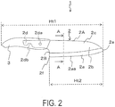
- a ceramic cutting tool 1 of the present disclosure has a blade body 2 containing zirconium oxide as a primary component.
- the blade body 2 contains particles containing any one of aluminum oxide, silicon carbide, or silicon nitride as a primary component.
- the total length Ht1 of the ceramic cutting tool 1 is, for example, not less than 8 cm and not greater than 40 cm.
- the ceramic cutting tool 1 includes the blade body 2 and a handle 3.
- part of the blade body 2 is disposed inside the handle 3.
- the ceramic cutting tool 1 may also be configured with only the blade body 2 without having a handle 3.
- the blade body 2 is set to a shape and size in accordance with an application as a cutting tool.
- the specific shape of the blade body 2 may be set to the shape of a Japanese kitchen knife such as a broad-bladed kitchen knife or an all-purpose kitchen knife, a Western kitchen knife such as a butcher knife, a Chinese kitchen knife, or the like, for example.
- the blade body 2 is not limited to a kitchen knife and may, for example, have the shape of a knife, a surgical instrument, or the like.
- the blade body 2 includes a base body exposed part 2c which is exposed from the handle 3, and a core 2d disposed inside the handle 3.
- the base body exposed part 2c includes a blade part 2a and a base body part 2b.
- the width of the core 2d may be set as needed and is determined, for example, by the relationship with the width of the base body exposed part 2c.
- a hole 2da is provided in the core 2d.
- a single hole 2da may be provided, or a plurality of holes 2da may be provided.
- the blade body 2 may be firmly fixed to the handle 3.
- the core 2d is provided with a hook 2db.
- the hook 2db is provided so that a notch is formed from a part of the core 2d.
- the hole 2da is formed into a circular shape with a radius of not less than 0.5 mm and not greater than 3 mm, for example.
- a metal plate may also be disposed inside the handle 3. When a metal plate is disposed inside the handle 3, it may be detected by a metal detector or the like.
- the handle 3 is made of a resin, ceramic, wood, or the like.
- resin materials include synthetic resins such as ethylene, polypropylene, and polyester, elastomer resins, so-called ABS resins, or materials prepared by vulcanizing synthetic rubbers to an appropriate hardness.
- An antimicrobial agent may be added to the resin, or it may be surface-treated with an antimicrobial agent as necessary.
- a resin having a bending modulus of elasticity of not less than 400 kg/cm 2 and not greater than 4000 kg/cm 2 , for example, and a compressive elastic modulus of not less than 520 kg/cm 2 and not greater than 3300 kg/cm 2 , for example, may be used.
- the width Ht3 (blade width) in a direction perpendicular to the total length Ht1 of the blade body 2 illustrated in FIG. 3 , which is a view facing the tip 2e of the ceramic cutting tool 1, may be set appropriately in accordance with the application of the ceramic cutting tool 1.
- the width Ht3 may be set to not less than 15 mm and not greater than 50 mm.
- the thickness Ht4 of the blade body 2 is the thickest part and may be set to not less than 1.3 mm and not greater than 5.0 mm, for example.
- the cutting blade ridge 2aa (simply referred to as the top part 2aa hereafter) of the blade part 2a is connected to the upper surface 2A (back) and the side surface 2B of the blade body 2.
- the tip 2e of the blade body 2 (more specifically, the blade part 2a) is curved.
- the curvature of the curve of the tip 2e of the blade body 2 is not less than 2 mm and not greater than 10 mm, for example.
- the curving of the tip 2e of the blade body 2 reduces the chipping of the tip 2e.
- the blade length (length of the portion with a blade edge) Ht2 of the blade body 2 may be set appropriately in accordance with the application, and when the ceramic cutting tool 1 is used as a general kitchen knife or the like, the blade length Ht2 may be set to not less than 5 cm and not greater than 20 cm, for example.
- the central end portion 2f to which the blade part 2a and the side surface 2B are connected may also be curved. As a result of such curving, chipping of the blade body 2a is suppressed.
- the curvature of the central end portion 2f is set to be smaller than the curvature of the tip 2e.
- the radius of curvature of the central end portion 2f is not less than 1 mm and not greater than 5 mm, for example.
- FIG. 4 is a cross-sectional view of the portion corresponding to the Zm region of FIG. 3 when the ceramic cutting tool 1 is cut along line A-A of FIGS. 1 and 2 .
- the blade part 2a of the blade body 2 includes two cutting edge side surfaces 2ab disposed at an angle so that the spacing narrows toward the top part 2aa from the base body part 2b.
- the top part 2aa corresponds to a surface interposed between the cutting blade ridge side edges of the two cutting edge side surfaces 2ab.
- the top part 2aa is illustrated as a flat surface, but the top part 2aa may also have a shape in which fine irregularities are disposed in a continuous manner.
- the width Yh of the top part 2aa When the width Yh of the top part 2aa is relatively small, the sharpness is enhanced, and when the width Yh of the top part 2aa is relatively large, defects such as so-called blade nicks are unlikely to occur.
- the width Yh of the top part 2aa is not less than 1 ⁇ m and not greater than 10 ⁇ m, the sharpness and durability are relatively high.
- the blade tip angle Dg of the blade part 2a is set to a range of 35° ⁇ 5° in the cross-sectional view, for example, the sharpness and the durability of the ceramic cutting tool 1 are, again, relatively high.
- the blade body 2 is made of a sintered compact of a ceramic material.
- the ceramic material constituting the blade body 2 is a material containing zirconium oxide (zirconia) as a primary component.
- a primary component refers to a component contained at a ratio of not less than 50 vol.%. In addition to zirconia, yttria or the like may also be contained as a stabilizer.
- the blade body 2 contains particles 4 containing any one of aluminum oxide, silicon carbide, or silicon nitride as a primary component.
- the particles 4 described here are particles with a higher Vickers hardness than zirconia.
- the primary component may be identified by measurements using an X-ray diffractometer.
- Al and O for example, are confirmed by an energy dispersive X-ray spectrometer attached to a scanning electron microscope, the composition may be considered aluminum oxide.
- the composition may be considered aluminum oxide.
- the zirconia content of the blade body 2 is not less than 50 vol.% and not greater than 95 vol.%, for example.
- the content of alumina particles (particles 4) is not less than 5 vol.% and less than 50 vol.%.
- the average particle size of the particles 4 is not less than 10 nm and not greater than 800 nm, for example.
- the average particle size may be calculated by measuring the particle diameter of the particles 4 present in an image magnified by 10000 times with a scanning electron microscope. Note that the average particle size may also be calculated by analyzing an image or photograph taken using a scanning electron microscope with image analysis software. When the average particle size is within the range described above, the sharpness of the ceramic cutting tool 1 is maintained over a relatively long period of time.
- the particles 4 are contained in the blade part 2a of the blade body 2. More specifically, as illustrated in FIGS. 5A and 5B , the particles 4 are positioned so that some of them are exposed from the top part 2aa of the blade part 2a. When the particles 4 are positioned so as to be exposed from the top part 2aa, the sharpness of the ceramic cutting tool 1 is relatively high.
- the particles 4 may also be distributed over the entire blade body 2. When the particles 4 are distributed over the entire blade body 2, it is possible to reduce the incidence of chipping or breaking of the blade body 2 over the entire blade body 2.
- the particles 4 may also be distributed and positioned in only certain regions of the blade part 2a including the top part 2aa. In this case, the blade tip portion of the blade part 2a is less likely to be chipped.
- the average particle size of the particles 4 may differ in accordance with the position of the blade body 2. For example, the average particle size of the particles 4 contained in the base body part 2b may be larger than the average particle size of the particles 4 contained in the blade part 2
- the particles 4 are positioned on the top part 2aa so that some of the particles are partially embedded inside a sintered compact containing zirconium oxide as a primary component.
- the particles are unlikely to drop off from the top part 2aa when an object is cut by the ceramic cutting tool 1, and the sharpness of the ceramic cutting tool 1 is maintained over a relatively long period of time.
- a plurality of particles 4 may be distributed and positioned so that the particles are distanced from one another.
- a plurality of aggregates each formed by the cohesion of a plurality of particles 4 may also be formed.
- the size of the aggregate of a plurality of particles 4 is not less than 500 nm and not greater than 5 ⁇ m for example.
- markings on the surface of the blade body 2 may also be markings on the surface of the blade body 2 (base body part 2b).
- the markings may be characters, figures, patterns, or designs. Having markings enhances the palatability to consumers.
- using markings containing the characters or figures of a manufacturer, vendor, or the like makes it possible to easily identify the manufacturer, vendor, or the like.
- the reflectance of portions with the marking may be lower than other portions of the blade body 2.
- the visibility of a portion with low reflectance is high.
- a laser is applied to the base body part 2b of the blade body 2, the surface is modified so as to give off a black color tone with low reflectance. Modification includes oxidation, carbonization, and the like, for example.
- the base body 2b containing particles 4 made of alumina exhibits a low transmittance in comparison to the base body 2b without the particles 4 (when the zirconia content is 100 vol.%).
- the base body part 2b is irradiated with a laser beam, the laser beam is unlikely to be diffused by the base body part 2b, and the surface becomes susceptible to modification by the laser beam.
- the markings on the ceramic cutting tool 1 assume a stronger black color than when the particles 4 made of alumina are not added. That is, the markings on the ceramic cutting tool 1 have a lower light reflectance than when the particles 4 made of alumina are not added. As a result, it is possible to enhance the visibility of the markings.
- Various methods may be used as a method of measuring the reflectance. For example, a microspectroscopic method or the like may be used.
- the ceramic cutting tool 1 described above can be produced with the following method, for example.
- a blade body 2 made of a ceramic is produced.
- the blade body 2 is produced, for example, by adding an alumina powder to a zirconia powder containing an yttria powder at a concentration of not less than 1.5 mol% and not greater than 4 mol%, adding an acrylic, wax, or polyethylene glycol-based binder in an amount of not less than 2 vol.% and not greater than 10 vol.%, and granulating the mixture.
- each powder is mixed so that the zirconia content is not less than 50 vol.% and not greater than 95 vol.%, for example, and so that the alumina content is not less than 5 vol.% and less than 50 vol.%, for example.
- the obtained granules are pressure-molded under conditions with a molding pressure of not less than 1000 kg/cm 2 and not greater than 1500 kg/cm 2 using a metal mold into the shape of the blade body 2 illustrated in FIG. 2 .
- the powder compact is then fired to obtain a zirconia sintered compact.
- the obtained zirconia sintered compact is edged so as to obtain a blade body 2 made of a ceramic.
- molding may be performed with a method ordinarily employed by a person skilled in the art in addition to molding using a metal mold. For example, slip casting, plastic molding (injection method), a rubber press method, a hot press method, an extrusion molding method, or the like may be used as needed.
- the firing temperature may be set appropriately in accordance with the material.
- the material is fired at a temperature of not lower than 1300°C and not higher than 1700°C, for example.
- the obtained zirconia sintered compact may be treated with a hot isotropic pressurization method as necessary, wherein the sintered compact is held at a pressure of not less than 1500 kg/cm 2 and not greater than 2500 kg/cm 2 for 2 to 5 hours.
- the blade body 2 is produced in this way.
- Polishing the blade body 2 produced in this way makes it possible to form the blade part 2a.
- a polishing material made of particles smaller than the average particle size of the particles 4 or to use a material having a Vickers hardness higher than that of zirconia and lower than that of the particles 4 made of alumina, for example.
- the zirconia portion is actively polished, and the dropping off of the particles 4 is suppressed, which makes it possible to dispose a plurality of particles 4 on the top part 2aa of the blade tip so that some of the particles are partially exposed.
- the handle 3 is then attached to the blade body 2 so that a core 2d is positioned on the inside.
- FIGS. 6 , 7A , and 7B The results of observing the ceramic cutting tool 1 produced using the ceramic cutting tool production method described above with a scanning electron microscope are illustrated in FIGS. 6 , 7A , and 7B .
- FIG. 6 illustrates the results of observing the top part 2aa of the ceramic cutting tool 1.
- FIG. 7A is a scanning electron microscope image in which the blade part 2a of the ceramic cutting tool 1 is observed at a magnification of 1000 times from the side surface.
- FIG. 7B is a scanning electron microscope image in which the blade part 2a of the ceramic cutting tool 1 is observed at a magnification of 10000 times from the side surface. Note that FIGS.
- 6 , 7A , and 7B are images obtained by measuring reflected electrons with a scanning electron microscope, and the portions with relatively dark color tones such as those present in the areas enclosed by the dotted lines correspond to the particles 4 containing alumina as a primary component.
- the blade body 2 contains a plurality of particles 4 containing alumina as a primary component, and the plurality of particles 4 are exposed on the top part 2aa of the blade body 2. Due to the particles 4, the sharpness of the ceramic cutting tool 1 becomes relatively high. In addition, as illustrated in FIGS. 7A and 7B , the particles 4 are distributed and positioned over the entire blade body 2. The overall hardness of the blade body 2 is relatively high so that the chipping or the like of the blade part 2a or the blade body is suppressed.
- a paper cutting test was performed by varying the amount of alumina particles (particles 4) added to the zirconia contained in the ceramic cutting tool 1.
- a paper cutting tests was performed using a so-called Hyundai sharpness tester. This paper cutting test examines how many sheets of paper can be cut when the cutting tool is pressed onto a stack of 400 sheets of paper with a prescribed pressure. The prescribed pressure was set to 6.2 (N). The results of measuring the initial (first cycle) sharpness and the sharpness of the 128th cycle are shown in Table 1 as a paper cutting test.
- the sharpness of the 128th cycle is enhanced when the zirconia content is not less than 50 vol.% and not greater than 95 vol.%, that is, when the alumina particle content is not less than 5 vol.% and less than 50 vol.%, in comparison to a conventional ceramic cutting tool containing no alumina particles (when the zirconia content in Table 1 is 100 vol.%).
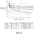
- FIG. 8 illustrates the sharpness test results up to the 128th cycle when the zirconia contains alumina particles in amounts of 20.9 vol.% (ZTA-20.9), 27.3 vol.% (ZTA-27.3), and 33.3 vol.% (ZTA-33.3). Note that ZTA-20.9, ZTA-27.3, and ZTA-33.3 are test pieces, and the shape of ZTA-0 is a kitchen knife.
- the results for ZTA-33.3, ZTA-27.3, and ZTA-20.9 are shown by the dotted lines, and the results for ZTA-0 are shown by the solid line. It can be seen from the results of FIG. 8 that the number of sheets cut in the paper cutting test is highest in order of ZTA-33.3, ZTA-27.3, ZTA-20.9, and then ZTA-0, so the sharpness is maintained in this order. That is, when the added amount of alumina particles is within this range, the sharpness is less likely to decrease than in the comparative example (ZTA-0) having a zirconia content of 100 vol.%.
Landscapes
- Chemical & Material Sciences (AREA)
- Engineering & Computer Science (AREA)
- Ceramic Engineering (AREA)
- Manufacturing & Machinery (AREA)
- Materials Engineering (AREA)
- Structural Engineering (AREA)
- Organic Chemistry (AREA)
- Composite Materials (AREA)
- Inorganic Chemistry (AREA)
- Mechanical Engineering (AREA)
- Forests & Forestry (AREA)
- Life Sciences & Earth Sciences (AREA)
- Physics & Mathematics (AREA)
- Optics & Photonics (AREA)
- Knives (AREA)
- Cutting Tools, Boring Holders, And Turrets (AREA)
Abstract
Description
- The present invention relates to a ceramic cutting tool.
- In recent years, ceramics, in particular, zirconia ceramics which exhibit relatively high wear resistance and toughness, have been used as materials for cutting tools such as kitchen knives (see
Patent Literatures -
- Patent Literature 1:
JP S62-159854 - Patent Literature 2:
JP 2004-358069 A - The ceramic cutting tool of the present disclosure has a blade body containing zirconium oxide as a primary component, and this blade body contains particles containing any one of aluminum oxide, silicon carbide, or silicon nitride as a primary component.
-
-
FIG. 1 is a plan view of a ceramic cutting tool. -
FIG. 2 is a partial perspective view of the ceramic cutting tool ofFIG. 1 . -
FIG. 3 is a view facing the tip of the ceramic cutting tool ofFIG. 1 . -
FIG. 4 is a cross-sectional view of the portion corresponding to the Zm region ofFIG. 3 when the ceramic cutting tool is cut along line A-A ofFIGS. 1 and2 . -
FIG. 5A is a schematic diagram of a view facing the top part of the ceramic cutting tool ofFIG. 1 . -
FIG. 5B is a cross-sectional schematic diagram when the ceramic cutting tool is cut along line B-B inFIG. 5A . -
FIG. 6 is a scanning electron microscope image in which the top part of the ceramic cutting tool is observed. -
FIG. 7A is a scanning electron microscope image in which the side surface of the blade part of the ceramic cutting tool is observed at a magnification of 1000 times. -
FIG. 7B is a scanning electron microscope image in which the side surface of the blade part of the ceramic cutting tool is observed at a magnification of 10000 times from a side surface side. -
FIG. 8 is a graph showing the results of a sharpness test of the ceramic cutting tool. - The ceramic cutting tool of the present disclosure will be described hereinafter with reference to the drawings. Note that the drawings used in the following explanations are schematic drawings, and the dimensional ratios and the like in the drawings do not necessarily match those of an actual cutting tool.
- The ceramic cutting tool of the present disclosure will be described hereinafter. A
ceramic cutting tool 1 of the present disclosure has ablade body 2 containing zirconium oxide as a primary component. Theblade body 2 contains particles containing any one of aluminum oxide, silicon carbide, or silicon nitride as a primary component. - The total length Ht1 of the
ceramic cutting tool 1 is, for example, not less than 8 cm and not greater than 40 cm. As illustrated inFIGS. 1 and2 , theceramic cutting tool 1 includes theblade body 2 and ahandle 3. In addition, as illustrated inFIG. 2 , part of theblade body 2 is disposed inside thehandle 3. Theceramic cutting tool 1 may also be configured with only theblade body 2 without having ahandle 3. - The
blade body 2 is set to a shape and size in accordance with an application as a cutting tool. The specific shape of theblade body 2 may be set to the shape of a Japanese kitchen knife such as a broad-bladed kitchen knife or an all-purpose kitchen knife, a Western kitchen knife such as a butcher knife, a Chinese kitchen knife, or the like, for example. Note that theblade body 2 is not limited to a kitchen knife and may, for example, have the shape of a knife, a surgical instrument, or the like. - The
blade body 2 includes a base body exposedpart 2c which is exposed from thehandle 3, and acore 2d disposed inside thehandle 3. The base body exposedpart 2c includes ablade part 2a and abase body part 2b. - The width of the
core 2d may be set as needed and is determined, for example, by the relationship with the width of the base body exposedpart 2c. A hole 2da is provided in thecore 2d. A single hole 2da may be provided, or a plurality of holes 2da may be provided. When a plurality of holes 2da are provided, theblade body 2 may be firmly fixed to thehandle 3. In this embodiment, thecore 2d is provided with a hook 2db. The hook 2db is provided so that a notch is formed from a part of thecore 2d. - The hole 2da is formed into a circular shape with a radius of not less than 0.5 mm and not greater than 3 mm, for example. In addition, it is possible to reduce the incidence of the
blade body 2 slipping out of thehandle 3 by fixing theblade body 2 to thehandle 3 via the hole 2da or the hook 2db. Further, a metal plate may also be disposed inside thehandle 3. When a metal plate is disposed inside thehandle 3, it may be detected by a metal detector or the like. - The
handle 3 is made of a resin, ceramic, wood, or the like. Examples of resin materials include synthetic resins such as ethylene, polypropylene, and polyester, elastomer resins, so-called ABS resins, or materials prepared by vulcanizing synthetic rubbers to an appropriate hardness. An antimicrobial agent may be added to the resin, or it may be surface-treated with an antimicrobial agent as necessary. When thehandle 3 is made of a resin, a resin having a bending modulus of elasticity of not less than 400 kg/cm2 and not greater than 4000 kg/cm2, for example, and a compressive elastic modulus of not less than 520 kg/cm2 and not greater than 3300 kg/cm2, for example, may be used. - The width Ht3 (blade width) in a direction perpendicular to the total length Ht1 of the
blade body 2 illustrated inFIG. 3 , which is a view facing thetip 2e of theceramic cutting tool 1, may be set appropriately in accordance with the application of theceramic cutting tool 1. For example, when theceramic cutting tool 1 is used as a general kitchen knife, the width Ht3 may be set to not less than 15 mm and not greater than 50 mm. The thickness Ht4 of theblade body 2 is the thickest part and may be set to not less than 1.3 mm and not greater than 5.0 mm, for example. - As illustrated in
FIGS. 1 and2 , the cutting blade ridge 2aa (simply referred to as the top part 2aa hereafter) of theblade part 2a is connected to theupper surface 2A (back) and theside surface 2B of theblade body 2. In the side views ofFIGS. 1 and2 , thetip 2e of the blade body 2 (more specifically, theblade part 2a) is curved. The curvature of the curve of thetip 2e of theblade body 2 is not less than 2 mm and not greater than 10 mm, for example. The curving of thetip 2e of theblade body 2 reduces the chipping of thetip 2e. The blade length (length of the portion with a blade edge) Ht2 of theblade body 2 may be set appropriately in accordance with the application, and when theceramic cutting tool 1 is used as a general kitchen knife or the like, the blade length Ht2 may be set to not less than 5 cm and not greater than 20 cm, for example. - As illustrated in
FIGS. 1 and2 , thecentral end portion 2f to which theblade part 2a and theside surface 2B are connected may also be curved. As a result of such curving, chipping of theblade body 2a is suppressed. The curvature of thecentral end portion 2f is set to be smaller than the curvature of thetip 2e. The radius of curvature of thecentral end portion 2f is not less than 1 mm and not greater than 5 mm, for example. - Next, the configuration of the
blade part 2a will be described usingFIG. 4 , which is a cross-sectional view of the portion corresponding to the Zm region ofFIG. 3 when theceramic cutting tool 1 is cut along line A-A ofFIGS. 1 and2 . Theblade part 2a of theblade body 2 includes two cutting edge side surfaces 2ab disposed at an angle so that the spacing narrows toward the top part 2aa from thebase body part 2b. The top part 2aa corresponds to a surface interposed between the cutting blade ridge side edges of the two cutting edge side surfaces 2ab. InFIG. 4 , the top part 2aa is illustrated as a flat surface, but the top part 2aa may also have a shape in which fine irregularities are disposed in a continuous manner. When the width Yh of the top part 2aa is relatively small, the sharpness is enhanced, and when the width Yh of the top part 2aa is relatively large, defects such as so-called blade nicks are unlikely to occur. For example, when the width Yh of the top part 2aa is not less than 1 µm and not greater than 10 µm, the sharpness and durability are relatively high. In addition, when the blade tip angle Dg of theblade part 2a is set to a range of 35° ± 5° in the cross-sectional view, for example, the sharpness and the durability of theceramic cutting tool 1 are, again, relatively high. - The
blade body 2 is made of a sintered compact of a ceramic material. The ceramic material constituting theblade body 2 is a material containing zirconium oxide (zirconia) as a primary component. A primary component refers to a component contained at a ratio of not less than 50 vol.%. In addition to zirconia, yttria or the like may also be contained as a stabilizer. - In the present disclosure, the
blade body 2 containsparticles 4 containing any one of aluminum oxide, silicon carbide, or silicon nitride as a primary component. Note that theparticles 4 described here are particles with a higher Vickers hardness than zirconia. In the specification of the primary component of theparticles 4, the primary component may be identified by measurements using an X-ray diffractometer. In addition, when Al and O, for example, are confirmed by an energy dispersive X-ray spectrometer attached to a scanning electron microscope, the composition may be considered aluminum oxide. Further, when it is confirmed that the substance is a powder and the regions where Al is present and the regions where O is present in the target powder overlap in a color mapping by an electron beam microanalyzer, the composition may be considered aluminum oxide. - A case in which the
particles 4 are made of aluminum oxide will be described hereinafter. The zirconia content of theblade body 2 is not less than 50 vol.% and not greater than 95 vol.%, for example. In theblade body 2, the content of alumina particles (particles 4) is not less than 5 vol.% and less than 50 vol.%. When zirconia and alumina particles are contained at such content ratios, the sharpness of theceramic cutting tool 1 is maintained over a relatively long period of time. - The average particle size of the
particles 4 is not less than 10 nm and not greater than 800 nm, for example. The average particle size may be calculated by measuring the particle diameter of theparticles 4 present in an image magnified by 10000 times with a scanning electron microscope. Note that the average particle size may also be calculated by analyzing an image or photograph taken using a scanning electron microscope with image analysis software. When the average particle size is within the range described above, the sharpness of theceramic cutting tool 1 is maintained over a relatively long period of time. - The
particles 4 are contained in theblade part 2a of theblade body 2. More specifically, as illustrated inFIGS. 5A and5B , theparticles 4 are positioned so that some of them are exposed from the top part 2aa of theblade part 2a. When theparticles 4 are positioned so as to be exposed from the top part 2aa, the sharpness of theceramic cutting tool 1 is relatively high. Theparticles 4 may also be distributed over theentire blade body 2. When theparticles 4 are distributed over theentire blade body 2, it is possible to reduce the incidence of chipping or breaking of theblade body 2 over theentire blade body 2. Theparticles 4 may also be distributed and positioned in only certain regions of theblade part 2a including the top part 2aa. In this case, the blade tip portion of theblade part 2a is less likely to be chipped. In addition, the average particle size of theparticles 4 may differ in accordance with the position of theblade body 2. For example, the average particle size of theparticles 4 contained in thebase body part 2b may be larger than the average particle size of theparticles 4 contained in theblade part 2a. - As illustrated in
FIG. 5B , theparticles 4 are positioned on the top part 2aa so that some of the particles are partially embedded inside a sintered compact containing zirconium oxide as a primary component. When some of theparticles 4 are positioned so as to be partially embedded in the top part 2aa, the particles are unlikely to drop off from the top part 2aa when an object is cut by theceramic cutting tool 1, and the sharpness of theceramic cutting tool 1 is maintained over a relatively long period of time. A plurality ofparticles 4 may be distributed and positioned so that the particles are distanced from one another. Alternatively, a plurality of aggregates each formed by the cohesion of a plurality ofparticles 4 may also be formed. The size of the aggregate of a plurality ofparticles 4 is not less than 500 nm and not greater than 5 µm for example. - There may also be markings on the surface of the blade body 2 (
base body part 2b). The markings may be characters, figures, patterns, or designs. Having markings enhances the palatability to consumers. In addition, using markings containing the characters or figures of a manufacturer, vendor, or the like makes it possible to easily identify the manufacturer, vendor, or the like. - The reflectance of portions with the marking may be lower than other portions of the
blade body 2. The visibility of a portion with low reflectance is high. Specifically, when a laser is applied to thebase body part 2b of theblade body 2, the surface is modified so as to give off a black color tone with low reflectance. Modification includes oxidation, carbonization, and the like, for example. Thebase body 2b containing particles 4 made of alumina exhibits a low transmittance in comparison to thebase body 2b without the particles 4 (when the zirconia content is 100 vol.%). In this case, when thebase body part 2b is irradiated with a laser beam, the laser beam is unlikely to be diffused by thebase body part 2b, and the surface becomes susceptible to modification by the laser beam. Therefore, when thebase body part 2b also contains theparticles 4, the markings on theceramic cutting tool 1 assume a stronger black color than when theparticles 4 made of alumina are not added. That is, the markings on theceramic cutting tool 1 have a lower light reflectance than when theparticles 4 made of alumina are not added. As a result, it is possible to enhance the visibility of the markings. Various methods may be used as a method of measuring the reflectance. For example, a microspectroscopic method or the like may be used. - The
ceramic cutting tool 1 described above can be produced with the following method, for example. - First, a
blade body 2 made of a ceramic is produced. Theblade body 2 is produced, for example, by adding an alumina powder to a zirconia powder containing an yttria powder at a concentration of not less than 1.5 mol% and not greater than 4 mol%, adding an acrylic, wax, or polyethylene glycol-based binder in an amount of not less than 2 vol.% and not greater than 10 vol.%, and granulating the mixture. When preparing granules, each powder is mixed so that the zirconia content is not less than 50 vol.% and not greater than 95 vol.%, for example, and so that the alumina content is not less than 5 vol.% and less than 50 vol.%, for example. - Next, the obtained granules are pressure-molded under conditions with a molding pressure of not less than 1000 kg/cm2 and not greater than 1500 kg/cm2 using a metal mold into the shape of the
blade body 2 illustrated inFIG. 2 . The powder compact is then fired to obtain a zirconia sintered compact. The obtained zirconia sintered compact is edged so as to obtain ablade body 2 made of a ceramic. Note that in the molding method described above, molding may be performed with a method ordinarily employed by a person skilled in the art in addition to molding using a metal mold. For example, slip casting, plastic molding (injection method), a rubber press method, a hot press method, an extrusion molding method, or the like may be used as needed. - The firing temperature may be set appropriately in accordance with the material. In the case of zirconia, the material is fired at a temperature of not lower than 1300°C and not higher than 1700°C, for example. After firing, the obtained zirconia sintered compact may be treated with a hot isotropic pressurization method as necessary, wherein the sintered compact is held at a pressure of not less than 1500 kg/cm2 and not greater than 2500 kg/cm2 for 2 to 5 hours. The
blade body 2 is produced in this way. - Polishing the
blade body 2 produced in this way makes it possible to form theblade part 2a. When polishing theblade body 2, it is preferable to use a polishing material made of particles smaller than the average particle size of theparticles 4 or to use a material having a Vickers hardness higher than that of zirconia and lower than that of theparticles 4 made of alumina, for example. By using such a polishing material, the zirconia portion is actively polished, and the dropping off of theparticles 4 is suppressed, which makes it possible to dispose a plurality ofparticles 4 on the top part 2aa of the blade tip so that some of the particles are partially exposed. Thehandle 3 is then attached to theblade body 2 so that acore 2d is positioned on the inside. - The results of observing the
ceramic cutting tool 1 produced using the ceramic cutting tool production method described above with a scanning electron microscope are illustrated inFIGS. 6 ,7A , and7B .FIG. 6 illustrates the results of observing the top part 2aa of theceramic cutting tool 1.FIG. 7A is a scanning electron microscope image in which theblade part 2a of theceramic cutting tool 1 is observed at a magnification of 1000 times from the side surface.FIG. 7B is a scanning electron microscope image in which theblade part 2a of theceramic cutting tool 1 is observed at a magnification of 10000 times from the side surface. Note thatFIGS. 6 ,7A , and7B are images obtained by measuring reflected electrons with a scanning electron microscope, and the portions with relatively dark color tones such as those present in the areas enclosed by the dotted lines correspond to theparticles 4 containing alumina as a primary component. - As illustrated in
FIG. 6 , theblade body 2 contains a plurality ofparticles 4 containing alumina as a primary component, and the plurality ofparticles 4 are exposed on the top part 2aa of theblade body 2. Due to theparticles 4, the sharpness of theceramic cutting tool 1 becomes relatively high. In addition, as illustrated inFIGS. 7A and7B , theparticles 4 are distributed and positioned over theentire blade body 2. The overall hardness of theblade body 2 is relatively high so that the chipping or the like of theblade part 2a or the blade body is suppressed. - Next, a paper cutting test was performed by varying the amount of alumina particles (particles 4) added to the zirconia contained in the
ceramic cutting tool 1. A paper cutting tests was performed using a so-called Honda sharpness tester. This paper cutting test examines how many sheets of paper can be cut when the cutting tool is pressed onto a stack of 400 sheets of paper with a prescribed pressure. The prescribed pressure was set to 6.2 (N). The results of measuring the initial (first cycle) sharpness and the sharpness of the 128th cycle are shown in Table 1 as a paper cutting test.[Table 1] Zirconia content (vol.%) Alumina particle content (vol.%) Initial (first cycle) 128th cycle Sharpness Sharpness 100% 0% 80 sheets 50 sheets 95% 5% 80 sheets 65 sheets 90% 10% 80 sheets 70 sheets 80% 20% 80 sheets 75 sheets 60% 40% 80 sheets 75 sheets 50% 50% 70 sheets 65 sheets 40% 60% 30 sheets 27 sheets - As a result, it can be seen that the sharpness of the 128th cycle is enhanced when the zirconia content is not less than 50 vol.% and not greater than 95 vol.%, that is, when the alumina particle content is not less than 5 vol.% and less than 50 vol.%, in comparison to a conventional ceramic cutting tool containing no alumina particles (when the zirconia content in Table 1 is 100 vol.%). In addition, the results indicated that the initial sharpness and the sharpness of the 128th cycle are both high when the zirconia content is not less than 50 vol.%.
- Further,
FIG. 8 illustrates the sharpness test results up to the 128th cycle when the zirconia contains alumina particles in amounts of 20.9 vol.% (ZTA-20.9), 27.3 vol.% (ZTA-27.3), and 33.3 vol.% (ZTA-33.3). Note that ZTA-20.9, ZTA-27.3, and ZTA-33.3 are test pieces, and the shape of ZTA-0 is a kitchen knife. - In
FIG. 8 , the results for ZTA-33.3, ZTA-27.3, and ZTA-20.9 are shown by the dotted lines, and the results for ZTA-0 are shown by the solid line. It can be seen from the results ofFIG. 8 that the number of sheets cut in the paper cutting test is highest in order of ZTA-33.3, ZTA-27.3, ZTA-20.9, and then ZTA-0, so the sharpness is maintained in this order. That is, when the added amount of alumina particles is within this range, the sharpness is less likely to decrease than in the comparative example (ZTA-0) having a zirconia content of 100 vol.%. - From the above results, it is possible to suppress decreases in initial sharpness and to maintain sharpness for a long period of time when the zirconia content is not less than 50 vol.% and less than 95 vol.% and the alumina particle content is not less than 5 vol.% and not greater than 50 vol.% in comparison to a conventional zirconia ceramic cutting tool. Quantitative analysis by fluorescent X-ray analysis, for example, may be performed to confirm the volume percent concentration in the
ceramic cutting tool 1. -
- 1 Ceramic cutting tool
- 2 Blade body
- 2a Blade part
- 2aa Top part
- 2b Base body part
- 2c Base body exposed part
- 2d Core
- 2da Hole
- 2db Hook
- 2e Tip
- 2f Central end portion
- 2A Upper surface
- 2B Side surface
- 3 Handle
- 4 Particle
Claims (7)
- A ceramic cutting tool comprising a blade body containing zirconium oxide as a primary component, wherein the blade body contains particles containing any one of aluminum oxide, silicon carbide, or silicon nitride as a primary component.
- The ceramic cutting tool according to claim 1, wherein the particles contain aluminum oxide as a primary component.
- The ceramic cutting tool according to claim 1 or 2, wherein the blade body includes a blade part, and a plurality of the particles are exposed on a top part of the blade part.
- The ceramic cutting tool according to claim 3, wherein a width of the top part in a short-side direction is not less than 1 µm and not greater than 10 µm.
- The ceramic cutting tool according to any one of claims 1 to 4, wherein an average particle size of the particles is not less than 10 nm and not greater than 400 nm.
- The ceramic cutting tool according to any one of claims 1 to 5, wherein the blade body contains the particles in an amount of not less than 5 vol.% and less than 50 vol.%.
- The ceramic cutting tool according to any one of claims 1 to 6, wherein the blade body further comprises markings on a surface thereof, and the markings have a lower light reflectance than other portions of the blade body.
Applications Claiming Priority (2)
| Application Number | Priority Date | Filing Date | Title |
|---|---|---|---|
| JP2015105088 | 2015-05-25 | ||
| PCT/JP2016/065424 WO2016190343A1 (en) | 2015-05-25 | 2016-05-25 | Ceramic knife |
Publications (3)
| Publication Number | Publication Date |
|---|---|
| EP3254812A1 true EP3254812A1 (en) | 2017-12-13 |
| EP3254812A4 EP3254812A4 (en) | 2018-01-10 |
| EP3254812B1 EP3254812B1 (en) | 2020-08-26 |
Family
ID=57393908
Family Applications (1)
| Application Number | Title | Priority Date | Filing Date |
|---|---|---|---|
| EP16800047.9A Active EP3254812B1 (en) | 2015-05-25 | 2016-05-25 | Ceramic knife |
Country Status (6)
| Country | Link |
|---|---|
| US (2) | US10118302B2 (en) |
| EP (1) | EP3254812B1 (en) |
| JP (2) | JP6151878B2 (en) |
| CN (1) | CN107405775B (en) |
| ES (1) | ES2820772T3 (en) |
| WO (1) | WO2016190343A1 (en) |
Families Citing this family (8)
| Publication number | Priority date | Publication date | Assignee | Title |
|---|---|---|---|---|
| WO2021242280A1 (en) * | 2020-05-27 | 2021-12-02 | Pacific Handy Cutter, Incorporated | Utility cutter assemblies, components for use in the assemblies, and related methods of manufacturing |
| JP6151878B2 (en) * | 2015-05-25 | 2017-06-21 | 京セラ株式会社 | Ceramic blade |
| JP6789319B2 (en) * | 2016-12-26 | 2020-11-25 | 京セラ株式会社 | Cutlery |
| JP6517418B1 (en) * | 2018-10-26 | 2019-05-22 | 株式会社レーベン | Cutting instrument and method of manufacturing the same |
| US20240190029A1 (en) * | 2021-03-31 | 2024-06-13 | Kyocera Corporation | Cutting implement |
| CN115533968B (en) * | 2022-09-29 | 2025-07-25 | 武汉苏泊尔炊具有限公司 | Tool and method for manufacturing the same |
| CN117383932A (en) * | 2023-10-11 | 2024-01-12 | 江苏利宇剃须刀有限公司 | A kind of preparation method of manual razor ceramic blade |
| CN121270278B (en) * | 2025-12-11 | 2026-03-20 | 成都西顿硬质合金有限公司 | A manufacturing process for high-strength ceramic knives |
Family Cites Families (27)
| Publication number | Priority date | Publication date | Assignee | Title |
|---|---|---|---|---|
| JPS6042275A (en) * | 1983-08-12 | 1985-03-06 | 住友化学工業株式会社 | Ceramic blade and manufacture |
| JPH0649111B2 (en) * | 1984-12-29 | 1994-06-29 | 京セラ株式会社 | Zirconia ceramic knife |
| JPS6230660A (en) * | 1985-07-30 | 1987-02-09 | 日立金属株式会社 | Blade of razor |
| JPH0513345Y2 (en) | 1986-03-29 | 1993-04-08 | ||
| JPS63318288A (en) * | 1987-06-19 | 1988-12-27 | 株式会社 リケン | Cutting tool |
| JPH02149465A (en) * | 1988-11-30 | 1990-06-08 | Toshiba Tungaloy Co Ltd | High-strength ceramic sintered body for tool |
| US5056227A (en) * | 1990-03-19 | 1991-10-15 | The Gillette Company | Razor blade technology |
| JPH04275977A (en) * | 1991-02-28 | 1992-10-01 | Osaka Cement Co Ltd | High strength alumina-zirconia ceramic edged tool |
| JP3487141B2 (en) * | 1997-08-19 | 2004-01-13 | 松下電工株式会社 | Ceramic knife |
| JP2000343146A (en) * | 1999-05-31 | 2000-12-12 | Ngk Spark Plug Co Ltd | Edged ceramic member, punching punch for manufacturing lead frame, method of manufacturing lead frame, and method of manufacturing edged ceramic member |
| JP2001277180A (en) * | 2000-03-30 | 2001-10-09 | Toray Ind Inc | Zirconia blade member and method of manufacturing the same |
| JP4741056B2 (en) * | 2000-06-05 | 2011-08-03 | 株式会社貝印刃物開発センター | Blade member and method of manufacturing the blade edge |
| WO2002083374A2 (en) * | 2001-04-17 | 2002-10-24 | Lazorblades, Inc. | Ceramic blade and production method therefor |
| US6701627B2 (en) * | 2001-07-26 | 2004-03-09 | American Saw & Mfg. Company, Inc. | Composite utility knife blade |
| US20040186493A1 (en) * | 2003-03-17 | 2004-09-23 | Mcwhorter Paul Jackson | Microkeratome cutting head assembly with single bevel cutting blade |
| JP3905062B2 (en) | 2003-06-06 | 2007-04-18 | 京セラ株式会社 | Ceramic knife |
| JP2005206392A (en) * | 2004-01-20 | 2005-08-04 | Toto Ltd | Method for producing zirconia sintered compact, and zirconia sintered compact |
| US20060207110A1 (en) * | 2005-03-03 | 2006-09-21 | Kyocera Corporation | Ceramic cutting knife |
| WO2007070745A2 (en) * | 2005-12-01 | 2007-06-21 | Mynosys Cellular Devices, Inc. | Micro surgical cutting instruments |
| WO2007092852A2 (en) * | 2006-02-06 | 2007-08-16 | Mynosys Cellular Devices, Inc. | Microsurgical cutting instruments |
| CN2897582Y (en) * | 2006-04-29 | 2007-05-09 | 山东硅苑新材料科技股份有限公司 | Ceramic knife |
| JP5511661B2 (en) | 2008-06-26 | 2014-06-04 | 京セラ株式会社 | Pink to purple ceramics and decorative parts |
| AU2009262100A1 (en) * | 2008-06-27 | 2009-12-30 | Sm Products, Llc | Scraper blade |
| AU2010340892B2 (en) | 2009-12-16 | 2014-10-09 | Ceramtec Gmbh | Ceramic composite material consisting of aluminium oxide and zirconium oxide as main constituents |
| JP5568649B1 (en) * | 2013-01-22 | 2014-08-06 | 日本航空電子工業株式会社 | Cutlery tool |
| JP6151878B2 (en) * | 2015-05-25 | 2017-06-21 | 京セラ株式会社 | Ceramic blade |
| US10730193B2 (en) * | 2015-06-22 | 2020-08-04 | Kyocera Corporation | Cutter |
-
2016
- 2016-05-25 JP JP2017515271A patent/JP6151878B2/en active Active
- 2016-05-25 US US15/556,629 patent/US10118302B2/en active Active
- 2016-05-25 CN CN201680014133.1A patent/CN107405775B/en active Active
- 2016-05-25 EP EP16800047.9A patent/EP3254812B1/en active Active
- 2016-05-25 ES ES16800047T patent/ES2820772T3/en active Active
- 2016-05-25 WO PCT/JP2016/065424 patent/WO2016190343A1/en not_active Ceased
-
2017
- 2017-05-25 JP JP2017103851A patent/JP6431131B2/en active Active
-
2018
- 2018-09-26 US US16/142,058 patent/US10821616B2/en active Active
Also Published As
| Publication number | Publication date |
|---|---|
| US20190022880A1 (en) | 2019-01-24 |
| EP3254812B1 (en) | 2020-08-26 |
| EP3254812A4 (en) | 2018-01-10 |
| JP2017192737A (en) | 2017-10-26 |
| JP6431131B2 (en) | 2018-11-28 |
| JP6151878B2 (en) | 2017-06-21 |
| ES2820772T3 (en) | 2021-04-22 |
| JPWO2016190343A1 (en) | 2017-07-06 |
| CN107405775A (en) | 2017-11-28 |
| CN107405775B (en) | 2018-12-18 |
| US10118302B2 (en) | 2018-11-06 |
| US20180056532A1 (en) | 2018-03-01 |
| WO2016190343A1 (en) | 2016-12-01 |
| US10821616B2 (en) | 2020-11-03 |
Similar Documents
| Publication | Publication Date | Title |
|---|---|---|
| EP3254812B1 (en) | Ceramic knife | |
| JP6774716B2 (en) | Cutlery | |
| JP6789319B2 (en) | Cutlery | |
| KR102402007B1 (en) | Razor blade | |
| KR101599201B1 (en) | Flat blade-shaped cutting blade and green sheet cutting blade | |
| JP6087363B2 (en) | Green sheet cutting blade | |
| KR102691168B1 (en) | Cemented carbide cutting blade | |
| ES2251351T3 (en) | SHEET MATERIALS CONTAINING PARTICLES OF DIAMOND OR CUBIC BORON NITRIDE FOR TOOLS OF SHARP EDGES SUCH AS A KITCHEN KNIFE. | |
| CN220742576U (en) | Ceramic pencil sharpener capable of greatly improving pencil sharpening times | |
| TW202210258A (en) | Cemented carbide cutting blade | |
| CN209887718U (en) | Cutter for cutting sheet molding compound | |
| JP4936860B2 (en) | Aperture mold | |
| Morrell | Fractography and fracture toughness measurement | |
| JP2000135388A (en) | Ceramic slicer | |
| CN116872642A (en) | A ceramic pencil sharpener that can greatly increase the number of pencil sharpening times | |
| Mendoza | Investigation of the Fracture Behavior of cBN-Glass Composites | |
| KR20040096113A (en) | Powder-sintered cutter comprising breakable blade |
Legal Events
| Date | Code | Title | Description |
|---|---|---|---|
| STAA | Information on the status of an ep patent application or granted ep patent |
Free format text: STATUS: THE INTERNATIONAL PUBLICATION HAS BEEN MADE |
|
| PUAI | Public reference made under article 153(3) epc to a published international application that has entered the european phase |
Free format text: ORIGINAL CODE: 0009012 |
|
| STAA | Information on the status of an ep patent application or granted ep patent |
Free format text: STATUS: REQUEST FOR EXAMINATION WAS MADE |
|
| 17P | Request for examination filed |
Effective date: 20170905 |
|
| AK | Designated contracting states |
Kind code of ref document: A1 Designated state(s): AL AT BE BG CH CY CZ DE DK EE ES FI FR GB GR HR HU IE IS IT LI LT LU LV MC MK MT NL NO PL PT RO RS SE SI SK SM TR |
|
| AX | Request for extension of the european patent |
Extension state: BA ME |
|
| A4 | Supplementary search report drawn up and despatched |
Effective date: 20171212 |
|
| RIC1 | Information provided on ipc code assigned before grant |
Ipc: C04B 35/48 20060101ALI20171205BHEP Ipc: B26B 9/00 20060101AFI20171205BHEP Ipc: C04B 35/64 20060101ALI20171205BHEP Ipc: C04B 35/488 20060101ALI20171205BHEP |
|
| DAV | Request for validation of the european patent (deleted) | ||
| DAX | Request for extension of the european patent (deleted) | ||
| STAA | Information on the status of an ep patent application or granted ep patent |
Free format text: STATUS: EXAMINATION IS IN PROGRESS |
|
| 17Q | First examination report despatched |
Effective date: 20181001 |
|
| GRAP | Despatch of communication of intention to grant a patent |
Free format text: ORIGINAL CODE: EPIDOSNIGR1 |
|
| STAA | Information on the status of an ep patent application or granted ep patent |
Free format text: STATUS: GRANT OF PATENT IS INTENDED |
|
| INTG | Intention to grant announced |
Effective date: 20200227 |
|
| GRAJ | Information related to disapproval of communication of intention to grant by the applicant or resumption of examination proceedings by the epo deleted |
Free format text: ORIGINAL CODE: EPIDOSDIGR1 |
|
| STAA | Information on the status of an ep patent application or granted ep patent |
Free format text: STATUS: EXAMINATION IS IN PROGRESS |
|
| INTC | Intention to grant announced (deleted) | ||
| RAP1 | Party data changed (applicant data changed or rights of an application transferred) |
Owner name: KYOCERA CORPORATION |
|
| GRAR | Information related to intention to grant a patent recorded |
Free format text: ORIGINAL CODE: EPIDOSNIGR71 |
|
| GRAS | Grant fee paid |
Free format text: ORIGINAL CODE: EPIDOSNIGR3 |
|
| STAA | Information on the status of an ep patent application or granted ep patent |
Free format text: STATUS: GRANT OF PATENT IS INTENDED |
|
| GRAA | (expected) grant |
Free format text: ORIGINAL CODE: 0009210 |
|
| STAA | Information on the status of an ep patent application or granted ep patent |
Free format text: STATUS: THE PATENT HAS BEEN GRANTED |
|
| INTG | Intention to grant announced |
Effective date: 20200716 |
|
| AK | Designated contracting states |
Kind code of ref document: B1 Designated state(s): AL AT BE BG CH CY CZ DE DK EE ES FI FR GB GR HR HU IE IS IT LI LT LU LV MC MK MT NL NO PL PT RO RS SE SI SK SM TR |
|
| REG | Reference to a national code |
Ref country code: GB Ref legal event code: FG4D |
|
| REG | Reference to a national code |
Ref country code: CH Ref legal event code: EP |
|
| REG | Reference to a national code |
Ref country code: DE Ref legal event code: R096 Ref document number: 602016042825 Country of ref document: DE |
|
| REG | Reference to a national code |
Ref country code: AT Ref legal event code: REF Ref document number: 1305927 Country of ref document: AT Kind code of ref document: T Effective date: 20200915 |
|
| REG | Reference to a national code |
Ref country code: IE Ref legal event code: FG4D |
|
| REG | Reference to a national code |
Ref country code: SE Ref legal event code: TRGR |
|
| REG | Reference to a national code |
Ref country code: LT Ref legal event code: MG4D |
|
| PG25 | Lapsed in a contracting state [announced via postgrant information from national office to epo] |
Ref country code: NO Free format text: LAPSE BECAUSE OF FAILURE TO SUBMIT A TRANSLATION OF THE DESCRIPTION OR TO PAY THE FEE WITHIN THE PRESCRIBED TIME-LIMIT Effective date: 20201126 Ref country code: BG Free format text: LAPSE BECAUSE OF FAILURE TO SUBMIT A TRANSLATION OF THE DESCRIPTION OR TO PAY THE FEE WITHIN THE PRESCRIBED TIME-LIMIT Effective date: 20201126 Ref country code: HR Free format text: LAPSE BECAUSE OF FAILURE TO SUBMIT A TRANSLATION OF THE DESCRIPTION OR TO PAY THE FEE WITHIN THE PRESCRIBED TIME-LIMIT Effective date: 20200826 Ref country code: FI Free format text: LAPSE BECAUSE OF FAILURE TO SUBMIT A TRANSLATION OF THE DESCRIPTION OR TO PAY THE FEE WITHIN THE PRESCRIBED TIME-LIMIT Effective date: 20200826 Ref country code: GR Free format text: LAPSE BECAUSE OF FAILURE TO SUBMIT A TRANSLATION OF THE DESCRIPTION OR TO PAY THE FEE WITHIN THE PRESCRIBED TIME-LIMIT Effective date: 20201127 Ref country code: PT Free format text: LAPSE BECAUSE OF FAILURE TO SUBMIT A TRANSLATION OF THE DESCRIPTION OR TO PAY THE FEE WITHIN THE PRESCRIBED TIME-LIMIT Effective date: 20201228 Ref country code: LT Free format text: LAPSE BECAUSE OF FAILURE TO SUBMIT A TRANSLATION OF THE DESCRIPTION OR TO PAY THE FEE WITHIN THE PRESCRIBED TIME-LIMIT Effective date: 20200826 |
|
| REG | Reference to a national code |
Ref country code: NL Ref legal event code: MP Effective date: 20200826 |
|
| REG | Reference to a national code |
Ref country code: AT Ref legal event code: MK05 Ref document number: 1305927 Country of ref document: AT Kind code of ref document: T Effective date: 20200826 |
|
| PG25 | Lapsed in a contracting state [announced via postgrant information from national office to epo] |
Ref country code: NL Free format text: LAPSE BECAUSE OF FAILURE TO SUBMIT A TRANSLATION OF THE DESCRIPTION OR TO PAY THE FEE WITHIN THE PRESCRIBED TIME-LIMIT Effective date: 20200826 Ref country code: LV Free format text: LAPSE BECAUSE OF FAILURE TO SUBMIT A TRANSLATION OF THE DESCRIPTION OR TO PAY THE FEE WITHIN THE PRESCRIBED TIME-LIMIT Effective date: 20200826 Ref country code: PL Free format text: LAPSE BECAUSE OF FAILURE TO SUBMIT A TRANSLATION OF THE DESCRIPTION OR TO PAY THE FEE WITHIN THE PRESCRIBED TIME-LIMIT Effective date: 20200826 Ref country code: RS Free format text: LAPSE BECAUSE OF FAILURE TO SUBMIT A TRANSLATION OF THE DESCRIPTION OR TO PAY THE FEE WITHIN THE PRESCRIBED TIME-LIMIT Effective date: 20200826 Ref country code: IS Free format text: LAPSE BECAUSE OF FAILURE TO SUBMIT A TRANSLATION OF THE DESCRIPTION OR TO PAY THE FEE WITHIN THE PRESCRIBED TIME-LIMIT Effective date: 20201226 |
|
| REG | Reference to a national code |
Ref country code: ES Ref legal event code: FG2A Ref document number: 2820772 Country of ref document: ES Kind code of ref document: T3 Effective date: 20210422 |
|
| PG25 | Lapsed in a contracting state [announced via postgrant information from national office to epo] |
Ref country code: EE Free format text: LAPSE BECAUSE OF FAILURE TO SUBMIT A TRANSLATION OF THE DESCRIPTION OR TO PAY THE FEE WITHIN THE PRESCRIBED TIME-LIMIT Effective date: 20200826 Ref country code: SM Free format text: LAPSE BECAUSE OF FAILURE TO SUBMIT A TRANSLATION OF THE DESCRIPTION OR TO PAY THE FEE WITHIN THE PRESCRIBED TIME-LIMIT Effective date: 20200826 Ref country code: RO Free format text: LAPSE BECAUSE OF FAILURE TO SUBMIT A TRANSLATION OF THE DESCRIPTION OR TO PAY THE FEE WITHIN THE PRESCRIBED TIME-LIMIT Effective date: 20200826 Ref country code: CZ Free format text: LAPSE BECAUSE OF FAILURE TO SUBMIT A TRANSLATION OF THE DESCRIPTION OR TO PAY THE FEE WITHIN THE PRESCRIBED TIME-LIMIT Effective date: 20200826 Ref country code: DK Free format text: LAPSE BECAUSE OF FAILURE TO SUBMIT A TRANSLATION OF THE DESCRIPTION OR TO PAY THE FEE WITHIN THE PRESCRIBED TIME-LIMIT Effective date: 20200826 |
|
| REG | Reference to a national code |
Ref country code: DE Ref legal event code: R097 Ref document number: 602016042825 Country of ref document: DE |
|
| PG25 | Lapsed in a contracting state [announced via postgrant information from national office to epo] |
Ref country code: AT Free format text: LAPSE BECAUSE OF FAILURE TO SUBMIT A TRANSLATION OF THE DESCRIPTION OR TO PAY THE FEE WITHIN THE PRESCRIBED TIME-LIMIT Effective date: 20200826 Ref country code: AL Free format text: LAPSE BECAUSE OF FAILURE TO SUBMIT A TRANSLATION OF THE DESCRIPTION OR TO PAY THE FEE WITHIN THE PRESCRIBED TIME-LIMIT Effective date: 20200826 |
|
| PG25 | Lapsed in a contracting state [announced via postgrant information from national office to epo] |
Ref country code: SK Free format text: LAPSE BECAUSE OF FAILURE TO SUBMIT A TRANSLATION OF THE DESCRIPTION OR TO PAY THE FEE WITHIN THE PRESCRIBED TIME-LIMIT Effective date: 20200826 |
|
| PLBE | No opposition filed within time limit |
Free format text: ORIGINAL CODE: 0009261 |
|
| STAA | Information on the status of an ep patent application or granted ep patent |
Free format text: STATUS: NO OPPOSITION FILED WITHIN TIME LIMIT |
|
| 26N | No opposition filed |
Effective date: 20210527 |
|
| PG25 | Lapsed in a contracting state [announced via postgrant information from national office to epo] |
Ref country code: SI Free format text: LAPSE BECAUSE OF FAILURE TO SUBMIT A TRANSLATION OF THE DESCRIPTION OR TO PAY THE FEE WITHIN THE PRESCRIBED TIME-LIMIT Effective date: 20200826 |
|
| REG | Reference to a national code |
Ref country code: CH Ref legal event code: PL |
|
| PG25 | Lapsed in a contracting state [announced via postgrant information from national office to epo] |
Ref country code: MC Free format text: LAPSE BECAUSE OF FAILURE TO SUBMIT A TRANSLATION OF THE DESCRIPTION OR TO PAY THE FEE WITHIN THE PRESCRIBED TIME-LIMIT Effective date: 20200826 Ref country code: LI Free format text: LAPSE BECAUSE OF NON-PAYMENT OF DUE FEES Effective date: 20210531 Ref country code: LU Free format text: LAPSE BECAUSE OF NON-PAYMENT OF DUE FEES Effective date: 20210525 Ref country code: CH Free format text: LAPSE BECAUSE OF NON-PAYMENT OF DUE FEES Effective date: 20210531 |
|
| REG | Reference to a national code |
Ref country code: BE Ref legal event code: MM Effective date: 20210531 |
|
| PG25 | Lapsed in a contracting state [announced via postgrant information from national office to epo] |
Ref country code: IE Free format text: LAPSE BECAUSE OF NON-PAYMENT OF DUE FEES Effective date: 20210525 |
|
| PG25 | Lapsed in a contracting state [announced via postgrant information from national office to epo] |
Ref country code: BE Free format text: LAPSE BECAUSE OF NON-PAYMENT OF DUE FEES Effective date: 20210531 |
|
| REG | Reference to a national code |
Ref country code: FR Ref legal event code: PLFP Year of fee payment: 8 |
|
| PG25 | Lapsed in a contracting state [announced via postgrant information from national office to epo] |
Ref country code: HU Free format text: LAPSE BECAUSE OF FAILURE TO SUBMIT A TRANSLATION OF THE DESCRIPTION OR TO PAY THE FEE WITHIN THE PRESCRIBED TIME-LIMIT; INVALID AB INITIO Effective date: 20160525 |
|
| P01 | Opt-out of the competence of the unified patent court (upc) registered |
Effective date: 20230505 |
|
| PG25 | Lapsed in a contracting state [announced via postgrant information from national office to epo] |
Ref country code: CY Free format text: LAPSE BECAUSE OF FAILURE TO SUBMIT A TRANSLATION OF THE DESCRIPTION OR TO PAY THE FEE WITHIN THE PRESCRIBED TIME-LIMIT Effective date: 20200826 |
|
| PG25 | Lapsed in a contracting state [announced via postgrant information from national office to epo] |
Ref country code: MK Free format text: LAPSE BECAUSE OF FAILURE TO SUBMIT A TRANSLATION OF THE DESCRIPTION OR TO PAY THE FEE WITHIN THE PRESCRIBED TIME-LIMIT Effective date: 20200826 |
|
| PG25 | Lapsed in a contracting state [announced via postgrant information from national office to epo] |
Ref country code: MT Free format text: LAPSE BECAUSE OF FAILURE TO SUBMIT A TRANSLATION OF THE DESCRIPTION OR TO PAY THE FEE WITHIN THE PRESCRIBED TIME-LIMIT Effective date: 20200826 |
|
| PGFP | Annual fee paid to national office [announced via postgrant information from national office to epo] |
Ref country code: DE Payment date: 20250402 Year of fee payment: 10 |
|
| PGFP | Annual fee paid to national office [announced via postgrant information from national office to epo] |
Ref country code: ES Payment date: 20250602 Year of fee payment: 10 |
|
| PGFP | Annual fee paid to national office [announced via postgrant information from national office to epo] |
Ref country code: IT Payment date: 20250422 Year of fee payment: 10 |
|
| PGFP | Annual fee paid to national office [announced via postgrant information from national office to epo] |
Ref country code: FR Payment date: 20250401 Year of fee payment: 10 |
|
| PGFP | Annual fee paid to national office [announced via postgrant information from national office to epo] |
Ref country code: SE Payment date: 20250411 Year of fee payment: 10 |
|
| PG25 | Lapsed in a contracting state [announced via postgrant information from national office to epo] |
Ref country code: TR Free format text: LAPSE BECAUSE OF FAILURE TO SUBMIT A TRANSLATION OF THE DESCRIPTION OR TO PAY THE FEE WITHIN THE PRESCRIBED TIME-LIMIT Effective date: 20200826 |
|
| PGFP | Annual fee paid to national office [announced via postgrant information from national office to epo] |
Ref country code: GB Payment date: 20260323 Year of fee payment: 11 |