EP3254780B1 - Verfahren zum herstellen eines metallbearbeitungswerkzeugs - Google Patents
Verfahren zum herstellen eines metallbearbeitungswerkzeugs Download PDFInfo
- Publication number
- EP3254780B1 EP3254780B1 EP17000814.8A EP17000814A EP3254780B1 EP 3254780 B1 EP3254780 B1 EP 3254780B1 EP 17000814 A EP17000814 A EP 17000814A EP 3254780 B1 EP3254780 B1 EP 3254780B1
- Authority
- EP
- European Patent Office
- Prior art keywords
- plastic
- layer
- tool
- partial
- region
- Prior art date
- Legal status (The legal status is an assumption and is not a legal conclusion. Google has not performed a legal analysis and makes no representation as to the accuracy of the status listed.)
- Active
Links
Images


Classifications
-
- B—PERFORMING OPERATIONS; TRANSPORTING
- B21—MECHANICAL METAL-WORKING WITHOUT ESSENTIALLY REMOVING MATERIAL; PUNCHING METAL
- B21D—WORKING OR PROCESSING OF SHEET METAL OR METAL TUBES, RODS OR PROFILES WITHOUT ESSENTIALLY REMOVING MATERIAL; PUNCHING METAL
- B21D37/00—Tools as parts of machines covered by this subclass
- B21D37/01—Selection of materials
-
- B—PERFORMING OPERATIONS; TRANSPORTING
- B21—MECHANICAL METAL-WORKING WITHOUT ESSENTIALLY REMOVING MATERIAL; PUNCHING METAL
- B21D—WORKING OR PROCESSING OF SHEET METAL OR METAL TUBES, RODS OR PROFILES WITHOUT ESSENTIALLY REMOVING MATERIAL; PUNCHING METAL
- B21D22/00—Shaping without cutting, by stamping, spinning, or deep-drawing
- B21D22/20—Deep-drawing
- B21D22/22—Deep-drawing with devices for holding the edge of the blanks
-
- B—PERFORMING OPERATIONS; TRANSPORTING
- B21—MECHANICAL METAL-WORKING WITHOUT ESSENTIALLY REMOVING MATERIAL; PUNCHING METAL
- B21D—WORKING OR PROCESSING OF SHEET METAL OR METAL TUBES, RODS OR PROFILES WITHOUT ESSENTIALLY REMOVING MATERIAL; PUNCHING METAL
- B21D37/00—Tools as parts of machines covered by this subclass
- B21D37/20—Making tools by operations not covered by a single other subclass
-
- B—PERFORMING OPERATIONS; TRANSPORTING
- B23—MACHINE TOOLS; METAL-WORKING NOT OTHERWISE PROVIDED FOR
- B23P—METAL-WORKING NOT OTHERWISE PROVIDED FOR; COMBINED OPERATIONS; UNIVERSAL MACHINE TOOLS
- B23P15/00—Making specific metal objects by operations not covered by a single other subclass or a group in this subclass
- B23P15/24—Making specific metal objects by operations not covered by a single other subclass or a group in this subclass dies
Definitions
- the invention relates to a method for producing a metalworking tool.
- a reshaping tool which has two partial shapes designed to be complementary to one another.
- the sheet metal component is arranged between the two partial forms.
- the two partial molds are then pressed against one another, the component being pressed and reshaped between the two partial molds.
- a deep-drawing tool for sheet metal is from the publication DE 31 28 251 A1 known.
- a flexible plastic insert in multiple thicknesses of the metal sheets is to be placed loosely on the deep-drawing tool, the plastic insert being produced by front molding.
- the plastic insert can slip on the deep-drawing tool.
- a tool and a method for producing a tool are described.
- the method spotting and adjustment effort when working shapes and surfaces into the tool during deep drawing and cutting can be reduced.
- the tool is coated with hard-elastic plastic with a thickness of 1-5 mm, the coating being produced with a reference sheet, whereby the coating can be applied to one or both sides of the tool.
- a surface is pretreated by roughening before the hard-elastic plastic is placed on it.
- the pamphlet DE 20 2013 012 173 U1 describes a device for carrying out a mechanical method for sequentially increasing an abrasion resistance and for reducing a frictional resistance of surfaces of tools and workpieces. It is provided that the tool remains soft as a whole, but that its surface is partially designed with low friction.
- the pamphlet DE 101 55 234 A1 describes a forming tool which comprises a portion which consists of a plastic in which a material with sliding properties is embedded.
- the forming tool is used, for example, for deep drawing metal parts.
- the method according to the invention is intended to provide a metalworking tool which has a first partial shape.
- a base body made of metal is provided, with a surface of the base body being divided into several areas or sections, with at least one area being roughened by a surface treatment measure, with a layer of plastic on the at least one roughened area containing at least has a material property, is applied.
- a metalworking tool embodied as a forming tool generally comprises two sub-forms which are complementary to one another, namely a first sub-form and a second sub-form.
- the at least one area is first roughened by the surface treatment measure. Subsequently, an adhesive is additionally applied to the at least one roughened area before the layer of plastic is applied to it. Accordingly, the layer made of plastic, which has at least one material property, is applied to the at least one roughened area on which the adhesive is also applied.
- the metalworking tool is designed for processing components or workpieces which, for example, consist of sheet metal, which is why the metalworking tool can also be referred to and / or designed as a sheet metal working tool.
- the metalworking tool is designed as a forming tool and / or parting tool.
- plastics usually two types or types of plastic, which differ from one another by at least one material property, are applied to at least two different areas or sections of the surface of the base body.
- the at least one material property of the plastic layer a type and thus a chemical composition of the plastic, a spring rate and / or an elasticity or a modulus of elasticity of the plastic, a coefficient of friction of the plastic and a thickness of the layer are taken into account and thus chosen and / or discontinued.
- the layers of plastic fastened to different areas of the metal surface differ at least in terms of the type or composition of the plastic and thus, as a rule, in terms of its Coefficient of friction and / or its spring stiffness and, in an embodiment, through the thickness of the respective layer.
- the plastic is glued to the at least one area or section of the base body via the adhesive.
- At least one casting mold is arranged on, for example, the machined area of the surface of the base body, the at least one casting mold and the at least one machined area of the surface enclosing at least one cavity, which is a negative mold for the section on the machined section to be applied plastic and thus forms the layer to be provided here.
- Liquid plastic is filled into the at least one cavity and cured, the plastic being connected to / on the at least one machined area with the surface of the base body and being arranged thereon and / or attached to it with the layer being provided.
- the at least one area is first machined during machining and thus roughened.
- the at least one area is milled and thus machined.
- a second part shape is provided, which is designed as a counterpart to the first part shape.
- This second partial shape thus has at least one recess on one surface which corresponds to the at least one layer on the surface of the first partial shape.
- the surfaces of the two partial shapes are designed to be complementary to one another.
- the surface of the second part shape is formed only and / or completely from metal in the embodiment.
- the metalworking tool for example a forming tool and / or parting tool, is produced by an embodiment of the method presented and is designed for processing, for example reshaping, a workpiece or component.
- the metalworking tool comprises a first part shape with a base body made of metal, the surface of which is divided into several areas, at least one area of the surface being roughened and machined. A layer of plastic, which has at least one material property, is applied and thus fastened to the at least one roughened area.
- a second part shape of the metalworking tool is designed as a counterpart to the first part shape.
- an adhesive is first applied to the at least one roughened area. Then the layer of plastic is to be applied to the adhesive.
- the metalworking tool is designed to reshape a workpiece or component made of metal, the workpiece or component to be reshaped generally being or being designated as sheet metal.
- the workpiece to be formed is between the first part shape, the surface of which is made of metal, and on which at least one layer of plastic with at least one material property is applied, and a second part shape, the surface of which is completely made of a hard material, e.g. Metal or one Material that contains minerals, for example concrete, is formed to be arranged.
- the two partial molds are to be pressed and / or pressed against each other, whereby the workpiece, ie through the two or between the two partial molds, is to be reshaped and therefore to be machined.
- the provision of at least one layer of plastic with at least one material property increases the coefficient of friction or coefficient of friction in that area of the surface of the first partial mold on which the at least one layer of plastic is applied, and increased the component made of metal, whereas a coefficient of friction between two parts made of metal is usually lower.
- a normal force or hold-down force which has to be applied between the two partial shapes when the component is reshaped, can be reduced while the holding force or holding force remains the same.
- the hold-down force By reducing the hold-down force, the component is not deformed or plasticized by the at least one layer made of plastic.
- tensile forces that otherwise occur with the metalworking tool which occur during a process such as cutting, deforming and / or embossing, are reduced, which also avoids distortion of the component or surface defects of the formed component.
- At least one area on the surface of the first part shape By deliberately defining the at least one area on the surface of the first part shape, selecting the at least one material property of the plastic and / or the thickness of the layer between the at least one area on which the at least one layer of plastic is attached and at least one further area the surface of the first part shape, which is only made of metal, to achieve variable contact ratios for the component to be formed.
- At least one further area of the surface of the first partial mold made of metal for example made of steel, is to be avoided by the usually sheet-like component deflecting during the forming process.
- a distribution of a force between the surface of the first part shape and the component is, inter alia, due to the height or thickness of the layer made of plastic, a shape of the surface of the at least one area coated with plastic and a type or type and / or composition of the plastic to control.
- the second partial mold made of metal forming a counter-geometry to the first partial mold, which is partially coated with plastic, whereby a high dimensional accuracy of the component to be formed is to be ensured.
- the adhesive for example an adhesion promoter, the adhesive being applied to the at least one area that has previously been roughened.
- liquid plastic is introduced into the at least one cavity and thus on the The surface is cast close to the contour, here by choosing a geometry of the layer made of plastic, e.g. B. to avoid shrinkage or inaccuracy, a defined structure or a defined allowance for the surface of the first part of the mold is to be provided.
- the casting mold here forms a negative mold for the at least one layer made of plastic with the base body that has already been machined beforehand. Accordingly, the base body also serves as a casting and / or molding tool for at least one layer of plastic.
- the base body made of metal it is possible to improve the adhesion of the plastic to be applied to it by means of a degree of roughening.
- the metalworking tool produced by the method is inter alia. possible to produce a sheet metal as a component to be machined with a largely constant thickness that varies only slightly. In addition, spotting effort can be reduced.
- tribological conditions can be specifically adapted, for example by increasing friction and reducing a necessary hold-down force.
- variable bearing components are to be provided on the effective surface of the first part shape.
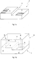
- FIG. 1a, 1b , 1c, 1d and 1e is shown schematically how a first partial mold 4 is produced as a component of the embodiment of the metalworking tool 6 from a base body 2 made of metal when the embodiment of the method according to the invention is carried out.
- At least one area 10, 12, here two areas 10, 12 or surfaces is first selected on a surface 8 of the base body 2, onto each of which a layer 14, 16 of plastic is to be applied or fastened as part of the method.
- the two areas 10, 12 on the surface 8 are roughened, for example by milling as a possible surface treatment measure ( Figure 1b ).
- an adhesive is applied to the roughened areas 10, 12 ( Figure 1c ).
- a casting mold 18 is arranged on the surface of the base body 2.
- the casting mold 18 comprises two recesses 20, 22, a first recess 20 being assigned to the first area 10 on the surface 8 of the base body 2 and a second recess 22 being assigned to the second area 12 on the surface 8 of the base body 2. It is further provided that the first region 10 on the surface 8 of the base body 2 and the first recess 20 enclose a first cavity 24. The second area 12 on the surface 8 of the base body 2 and the recess 22 of the casting mold 18 enclose a second cavity 26. In addition, each recess 20, 22 and thus each cavity 24, 26 is assigned a channel 54, 56 running inside the casting mold 18.
- liquid plastic is filled into the two cavities 24, 26 through the channels 54, 56, namely a first type or type of plastic in the first cavity 24 and / or a second type or type of plastic in the second cavity 26.
- different plastics can be used which have different chemical compositions and / or properties.
- the plastics harden within the respective cavities 24, 26, wherein the first layer 14 can be formed from the first type of plastic on the first area 10, which layer is attached to the roughened area 10 of the base body 8 provided with adhesive.
- the first layer 14 made of the first type of plastic includes a first thickness or height, a first coefficient of friction and a first spring stiffness.
- the second layer 16 made of the second type of plastic is attached to the second region 12 of the surface 8, this second layer being Layer 16 here can have a second thickness or height, a second coefficient of friction and a second spring stiffness.
- a thickness of a respective layer 14, 16 is to be monitored and controlled in a first step by an amount of the respective plastic to be filled in through the respective channel 54, 56, but for fine adjustment in a second step, if necessary, to be adjusted by post-processing.
- Figure 1e also shows a second part shape 28 as a further component of the metalworking tool 6.
- This second part shape 28 has a surface 30 that is complementary to the surface 8 of the base body 2 with the layers 14, 16 of plastic fastened thereon.
- the surface 30 of the second partial mold 28 is made of metal and has two recesses 42, 44 which are formed complementarily in the layers 14, 16 made of plastic on the surface 8 of the first partial mold 4.
- a component made of metal usually made of sheet metal
- it is to be arranged between the two partial molds 4, 28 of the metalworking tool 6.
- the two partial molds 4, 28 are then moved towards one another, the component being pressed between the partial molds 4, 28.
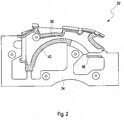
- Figure 2 shows a further example of a part shape 32 as a component of the second embodiment of the metalworking tool.
- This partial mold 32 also has a base body 34 made of metal, on which a plurality of layers 36, 38, 40 made of different types of plastic with different thicknesses are attached.
- This partial mold 32 is designed for reshaping a fender for a motor vehicle.
Landscapes
- Engineering & Computer Science (AREA)
- Mechanical Engineering (AREA)
- Chemical & Material Sciences (AREA)
- Materials Engineering (AREA)
- Mounting, Exchange, And Manufacturing Of Dies (AREA)
Description
- Die Erfindung betrifft ein Verfahren zum Herstellen eines Metallbearbeitungswerkzeugs.
- Zum Umformen eines Bauteils aus Blech wird ein Umformwerkzeug verwendet, das zwei zueinander komplementär ausgebildete Teilformen aufweist. Hierzu wird das Bauteil aus Blech zwischen den beiden Teilformen angeordnet. Danach werden die beiden Teilformen gegeneinander gedrückt, wobei das Bauteil zwischen den beiden Teilformen gepresst und umgeformt wird.
- Ein Tiefziehwerkzeug für Bleche ist aus der Druckschrift
DE 31 28 251 A1 bekannt. Hierbei ist zum Ausgleich einer Schwankung einer Dicke der Bleche durch eine nicht-metallische Schicht ein weichelastischer Kunststoffeinsatz in mehrfacher Stärke der Bleche lose auf dem Tiefziehwerkzeug aufzulegen, wobei der Kunststoffeinsatz durch einen Frontformguss herzustellen ist. Allerdings kann der Kunststoffeinsatz auf dem Tiefziehwerkzeug verrutschen. - In der Druckschrift
DE 10 2013 016 255 A1 sind ein Werkzeug und ein Verfahren zur Herstellung eines Werkzeugs beschrieben. Mit dem Verfahren sind ein Tuschier- und Abstimmaufwand bei einem Einarbeiten von Formen und Flächen in das Werkzeug beim Tiefziehen und Schneiden zu reduzieren. Hierzu wird das Werkzeug mit hartelastischem Kunststoff mit einer Dicke von 1- 5 mm beschichtet, wobei die Beschichtung mit einem Referenzblech erzeugt wird, wobei die Beschichtung auf einer oder auf beiden Werkzeugseiten aufgebracht sein kann. Dabei wird eine Fläche, bevor darauf der hartelastische Kunststoff angeordnet wird, durch Aufrauen vorbehandelt. In der DruckschriftDE 20 2013 012 173 U1 ist eine Vorrichtung zur Durchführung eines mechanischen Verfahrens zur sequenziellen Erhöhung einer Abriebfestigkeit und zur Verringerung eines Reibwiderstands von Oberflächen von Werkzeugen und Werkstücken beschrieben. Hierbei ist vorgesehen, dass das Werkzeug im Ganzen weich bleibt, jedoch seine Oberfläche partiell reibungsarm ausgestaltet wird. - Die Druckschrift
DE 101 55 234 A1 beschreibt ein Umformwerkzeug, das einen Teilbereich umfasst, der aus einem Kunststoff besteht, in den ein Material mit Gleiteigenschaften eingelagert ist. Das Umformwerkzeug wird beispielsweise für das Tiefziehen von Metallteilen eingesetzt. - Vor diesem Hintergrund wird ein Verfahren mit den Merkmalen des unabhängigen Patentanspruchs 1 vorgestellt. Ausgestaltungen des Verfahrens gehen aus den abhängigen Patentansprüchen und der Beschreibung hervor.
- Das erfindungsgemäße Verfahren ist zum Bereitstellen eines Metallbearbeitungswerkzeugs, das eine erste Teilform aufweist, vorgesehen. Zum Herstellen der ersten Teilform wird ein Grundkörper aus Metall bereitgestellt, wobei eine Oberfläche des Grundkörpers in mehrere Bereiche bzw. Abschnitte aufgeteilt wird, wobei mindestens ein Bereich durch eine Oberflächenbearbeitungsmaßnahme aufgeraut wird, wobei auf dem mindestens einen aufgerauten Bereich eine Schicht aus Kunststoff, die mindestens eine Materialeigenschaft aufweist, aufgebracht wird.
- Ein beispielsweise als Umformwerkzeug ausgebildetes Metallbearbeitungswerkzeug umfasst in der Regel zwei zueinander komplementär ausgebildete Teilformen, nämlich eine erste Teilform und eine zweite Teilform.
- In Ausgestaltung wird der mindestens eine Bereich zunächst durch die Oberflächenbearbeitungsmaßnahme aufgeraut. Nachfolgend wird auf dem mindestens einen aufgerauten Bereich ergänzend ein Haftmittel aufgetragen, bevor darauf die Schicht aus Kunststoff aufgebracht wird. Demnach wird dem mindestens einen aufgerauten Bereich, auf dem weiterhin das Haftmittel aufgetragen ist, die Schicht aus Kunststoff, die mindestens eine Materialeigenschaft aufweist, aufgebracht.
- Das Metallbearbeitungswerkzeug ist zum Bearbeiten von Bauteilen oder Werkstücken ausgebildet, die bspw. aus Blech bestehen, weshalb das Metallbearbeitungswerkzeug auch als Blechbearbeitungswerkzeug zu bezeichnen und/oder ausgebildet ist. In Ausgestaltung ist das Metallbearbeitungswerkzeug als Umformwerkzeug und/oder Trennwerkzeug ausgebildet.
- In Ausgestaltung werden auf mindestens zwei unterschiedlichen Bereichen bzw. Abschnitten der Oberfläche des Grundkörpers Kunststoffe, üblicherweise zwei Arten bzw. Sorten Kunststoff, aufgebracht, die sich durch mindestens eine Materialeigenschaft voneinander unterscheiden.
- Als die mindestens eine Materialeigenschaft der Schicht aus Kunststoff wird bzw. werden eine Art und somit eine chemische Zusammensetzung des Kunststoffs, eine Federhärte und/oder eine Elastizität bzw. ein E-Modul des Kunststoffs, ein Reibwert des Kunststoffs sowie eine Dicke der Schicht berücksichtigt und somit gewählt und/oder eingestellt. Die auf unterschiedlichen Bereichen der Oberfläche aus Metall befestigten Schichten aus Kunststoff unterscheiden sich mindestens durch die Art bzw. Zusammensetzung des Kunststoffs und somit in der Regel durch dessen Reibwert und/oder dessen Federhärte sowie in Ausgestaltung durch die Dicke der jeweiligen Schicht.
- Üblicherweise wird der Kunststoff über das Haftmittel auf den mindestens einen Bereich bzw. Abschnitt des Grundkörpers geklebt.
- Bei einer Ausgestaltung des Verfahrens wird an, bspw. auf dem bearbeiteten Bereich der Oberfläche des Grundkörpers mindestens eine Gussform angeordnet, wobei die mindestens eine Gussform und der mindestens eine bearbeitete Bereich der Oberfläche mindestens einen Hohlraum umschließen, der eine Negativform für den auf dem bearbeiteten Abschnitt aufzutragenden Kunststoff und somit die hierbei bereitzustellende Schicht bildet. In den mindestens einen Hohlraum wird flüssiger Kunststoff gefüllt und ausgehärtet, wobei der Kunststoff an/auf dem mindestens einen bearbeiteten Bereich mit der Oberfläche des Grundkörpers verbunden und unter Bereitstellung der Schicht darauf angeordnet und/oder damit bzw. daran befestigt wird.
- In der Regel wird der mindestens eine Bereich beim Bearbeiten zunächst spanend bearbeitet und somit aufgeraut. In Ausgestaltung wird der mindestens eine Bereich gefräst und somit spanend bearbeitet.
- Als weitere Komponente des Metallbearbeitungswerkzeugs wird neben der ersten Teilform eine zweite Teilform bereitgestellt, die als Gegenstück zu der ersten Teilform ausgebildet ist. So weist diese zweite Teilform an einer Oberfläche mindestens eine Ausnehmung auf, die zu der mindestens einen Schicht auf der Oberfläche der ersten Teilform korrespondiert. In der Regel sind die Oberflächen der beiden Teilformen zueinander komplementär ausgebildet.
- Die Oberfläche der zweiten Teilform ist in Ausgestaltung nur und/oder komplett aus Metall gebildet.
- Das Metallbearbeitungswerkzeug, bspw. ein Umformwerkzeug und/oder Trennwerkzeug, ist durch eine Ausführungsform des vorgestellten Verfahrens herzustellen und zum Bearbeiten, bspw. Umformen, eines Werkstücks bzw. Bauteils ausgebildet.
- Das Metallbearbeitungswerkzeug umfasst eine erste Teilform mit einem Grundkörper aus Metall, dessen Oberfläche in mehrere Bereiche aufgeteilt ist, wobei mindestens ein Bereich der Oberfläche aufgeraut und bearbeitet ist. Auf dem mindestens einen aufgerauten Bereich ist eine Schicht aus Kunststoff, die mindestens eine Materialeigenschaft aufweist, aufgebracht und somit befestigt. Eine zweite Teilform des Metallbearbeitungswerkzeugs ist als Gegenstück zu der ersten Teilform ausgebildet.
- In einer alternativen Ausgestaltung ist auf dem mindestens einen aufgerauten Bereich zunächst ein Haftmittel aufgetragen. Danach ist auf das Haftmittel die Schicht aus Kunststoff aufzutragen.
- Das Metallbearbeitungswerkzeug ist in Ausgestaltung zum Umformen eines Werkstücks bzw. Bauteils aus Metall ausgebildet, wobei das umzuformende Werkstück bzw. Bauteil in der Regel als Blech ausgebildet wird oder zu bezeichnen ist.
- Bei einem Betrieb des Metallbearbeitungswerkzeugs ist das umzuformende Werkstück zwischen der ersten Teilform, deren Oberfläche aus Metall gebildet ist, und auf der mindestens eine Schicht Kunststoff mit mindestens einer Materialeigenschaft aufgetragen ist, und einer zweiten Teilform, deren Oberfläche komplett aus einem harten Material, bspw. Metall oder einem Werkstoff, der Minerale enthält, bspw. Beton, gebildet ist, anzuordnen. Die beiden Teilformen sind gegeneinander zu drücken und/oder zu pressen, wodurch das Werkstück, d. h. durch die beiden bzw. zwischen den beiden Teilformen, umzuformen und demnach zu bearbeiten ist.
- Im Vergleich zu einem üblichem Metallbearbeitungswerkzeug, dessen beide Teilformen komplett aus Metall gebildet sind, wird durch Vorsehen mindestens einer Schicht aus Kunststoff mit mindestens einer Materialeigenschaft der Reibwert bzw. Reibkoeffizient in jenem Bereich der Oberfläche der ersten Teilform, auf der die mindestens eine Schicht aus Kunststoff aufgebracht ist, und dem Bauteil aus Metall erhöht, wohingegen ein Reibwert zwischen zwei Teilen aus Metall in der Regel geringer ist. Somit kann bei Einsatz des Metallbearbeitungswerkzeugs eine Normalkraft bzw. Niederhaltekraft, die zwischen den beiden Teilformen bei einem Umformen des Bauteils aufzubringen ist, bei gleichbleibender Haltekraft bzw. Rückhaltekraft reduziert werden. Durch Reduktion der Niederhaltekraft wird das Bauteil durch die mindestens eine Schicht aus Kunststoff nicht verformt bzw. plastifiziert. Ferner werden mit dem Metallbearbeitungswerkzeug ansonsten auftretende Zugkräfte, die bei einem Prozess wie Schneiden, Verformen und/oder Prägen auftreten, vermindert, wodurch auch ein Verzug des Bauteils oder Oberflächenfehler des umgeformten Bauteils vermieden werden.
- Durch gezieltes Festlegen des mindestens einen Bereichs auf der Oberfläche der ersten Teilform sind durch Auswahl der mindestens einen Materialeigenschaft des Kunststoffs und/oder der Dicke der Schicht zwischen dem mindestens einen Bereich, auf dem die mindestens eine Schicht Kunststoff befestigt ist, und mindestens einem weiteren Bereich der Oberfläche der ersten Teilform, der lediglich aus Metall gebildet ist, für das umzuformende Bauteil veränderliche Traganteile zu erreichen. Durch den mindestens einen weiteren Bereich der Oberfläche der ersten Teilform aus Metall, bspw. aus Stahl, ist ein Ausweichen des üblicherweise blechförmigen Bauteils beim Umformen zu vermeiden. Eine Verteilung einer Kraft zwischen der Oberfläche der ersten Teilform und dem Bauteil ist unter anderem durch die Höhe bzw. Dicke der Schicht aus Kunststoff, eine Form der Fläche des mindestens einen mit Kunststoff beschichteten Bereichs und eine Art bzw. Sorte und/oder Zusammensetzung des Kunstoffs zu steuern.
- Üblicherweise wird lediglich eine der beiden Teilformen mit Kunststoff beschichtet, wobei die zweite Teilform aus Metall eine Gegengeometrie zu der ersten, teilweise mit Kunststoff beschichteten Teilform bildet, wobei hierdurch eine hohe maßliche Genauigkeit des umzuformenden Bauteils zu gewährleisten ist. Beim Herstellen der ersten Teilform wird mindestens ein definierter Bereich auf der Oberfläche des Grundkörpers aus Metall grob gefräst und somit aufgeraut. Danach wird der mindestens eine aufgeraute Bereich mit dem Haftmittel, bspw. einem Haftvermittler, bestrichen, wobei das Haftmittel auf dem mindestens einem Bereich, der zuvor aufgeraut worden ist, aufgetragen wird.
- Durch Einsatz der Gussform, die auf den mindestens einen bearbeiteten Bereich des Grundkörpers angeordnet wird, wobei sich zwischen der Gussform und dem mindestens einen Bereich auf der Oberfläche des Grundkörpers mindestens ein Hohlraum befindet, wird in den mindestens einen Hohlraum flüssiger Kunststoff eingeführt und somit auf der Oberfläche konturnah aufgegossen, wobei hier durch Wahl einer Geometrie der Schicht aus Kunststoff, z. B. zur Vermeidung eines Schwunds oder einer Ungenauigkeit, eine definierte Struktur bzw. ein definiertes Aufmaß der Oberfläche der ersten Teilform bereitzustellen ist.
- Die Gussform bildet hierbei mit dem bereits vorab bearbeiteten Grundkörper eine negative Form für die mindestens eine Schicht aus Kunststoff. Demnach dient der Grundkörper auch als Guss- und oder Formwerkzeug für mindestens eine Schicht aus Kunststoff. Bei dem Bearbeiten des Grundkörpers aus Metall ist es möglich, durch einen Grad einer Aufrauung eine Haftung des darauf aufzutragenden Kunststoffs zu verbessern. Durch Einsatz der Gussform zum Herstellen der mindestens einen Schicht auf der Oberfläche der ersten Teilform ist diese schnell und unter geringem Aufwand mechanisch zu bearbeiten, da nunmehr Schnitt- und Vorschubparameter erhöht werden können.
- Mit dem durch das Verfahren hergestellten Metallbearbeitungswerkzeug ist es u. a. möglich, ein Blech als zu bearbeitendes Bauteil mit einer weitgehend konstanten Dicke, die nur geringfügig variiert, herzustellen. Außerdem kann ein Tuschieraufwand reduziert werden. Durch Vorsehen der mindestens einen Schicht aus Kunststoff sind bspw. durch Erhöhung einer Reibung sowie Reduzierung einer nötigen Niederhaltekraft tribologische Bedingungen gezielt anzupassen. Weiterhin sind in Abhängigkeit von Funktionen und Prozessen auf der wirksamen Oberfläche der ersten Teilform veränderliche Traganteile bereitzustellen. Beim Herstellen des Metallbearbeitungswerkzeugs und/oder bei dessen Einsatz kann auf ansonsten übliche Werkzeuge oder Bauteile aus Blech verzichtet werden. Weiterhin ist die erste Teilform beschleunigt zu bearbeiten.
- Weitere Vorteile und Ausgestaltungen der Erfindung ergeben sich aus der Beschreibung und den beiliegenden Zeichnungen.
- Es versteht sich, dass die voranstehend genannten und die nachstehend noch zu erläuternden Merkmale nicht nur in der jeweils angegebenen Kombination, sondern auch in anderen Kombinationen oder in Alleinstellung verwendbar sind, ohne den Rahmen der vorliegenden Erfindung zu verlassen.
- Die Erfindung ist anhand von Ausführungsformen in den Zeichnungen schematisch dargestellt und wird unter Bezugnahme auf die Zeichnungen schematisch und ausführlich beschrieben.
-
Figur 1 zeigt in schematischer Darstellung Schritte einer Ausführungsform des erfindungsgemäßen Verfahrens, bei dem eine erste Ausführungsform des Metallbearbeitungswerkzeugs hergestellt wird. -
Figur 2 zeigt in schematischer Darstellung ein Detail einer zweiten Ausführungsform des Metallbearbeitungswerkzeugs. - Die Figuren werden zusammenhängen und übergreifend beschrieben, gleichen Komponenten sind dieselben Bezugsziffern zugeordnet.
- Anhand der
Figuren 1a, 1b ,1c, 1d und1e ist schematisch dargestellt, wie bei Durchführung der Ausführungsform des erfindungsgemäßen Verfahrens aus einem Grundkörper 2 aus Metall eine erste Teilform 4 als Komponente der Ausführungsform des Metallbearbeitungswerkzeugs 6 hergestellt wird. - Hierbei wird zunächst auf einer Oberfläche 8 des Grundkörpers 2 mindestens ein Bereich 10, 12, hier zwei Bereiche 10, 12 bzw. Flächen, ausgewählt, auf die im Rahmen des Verfahrens jeweils eine Schicht 14, 16 aus Kunststoff aufzubringen bzw. zu befestigen ist. Hierbei werden die beiden Bereiche 10, 12 auf der Oberfläche 8 bspw. durch Fräsen als mögliche Oberflächenbearbeitungsmaßnahme aufgeraut (
Figur 1b ). Danach wird auf die aufgerauten Bereiche 10, 12 ein Haftmittel aufgetragen (Figur 1c ). In einem weiteren Schritt (Figur 1d ) ist vorgesehen, dass auf der Oberfläche des Grundkörpers 2 eine Gussform 18 angeordnet wird. - Dabei umfasst die Gussform 18 zwei Ausnehmungen 20, 22, wobei eine erste Ausnehmung 20 dem ersten Bereich 10 auf der Oberfläche 8 des Grundkörpers 2 und eine zweite Ausnehmung 22 dem zweiten Bereich 12 auf der Oberfläche 8 des Grundkörpers 2 zugeordnet ist. Weiterhin ist vorgesehen, dass der erste Bereich 10 auf der Oberfläche 8 des Grundkörpers 2 und die erste Ausnehmung 20 einen ersten Hohlraum 24 umschließen. Der zweite Bereich 12 auf der Oberfläche 8 des Grundkörpers 2 und die Ausnehmung 22 der Gussform 18 umschließen einen zweiten Hohlraum 26. Außerdem ist jeder Ausnehmung 20, 22 und somit jedem Hohlraum 24, 26 ein innerhalb der Gussform 18 verlaufender Kanal 54, 56 zugeordnet.
- Weiterhin wird in die beiden Hohlräume 24, 26 durch die Kanäle 54, 56 flüssiger Kunststoff eingefüllt und zwar in den ersten Hohlraum 24 eine erste Art bzw. Sorte Kunststoff und/oder in den zweiten Hohlraum 26 eine zweite Art bzw. Sorte Kunststoff. Somit können unterschiedliche Kunststoffe verwendet werden, die unterschiedliche chemische Zusammensetzungen und/oder Eigenschaften aufweisen. Die Kunststoffe härten innerhalb der jeweiligen Hohlräume 24, 26 aus, wobei auf dem ersten Bereich 10 die erste Schicht 14 aus der ersten Art Kunststoff gebildet werden kann, der auf dem aufgerauten und mit Haftmittel versehenen Bereich 10 des Grundkörpers 8 befestigt ist.
- Dabei umfasst die erste Schicht 14 aus der ersten Art Kunststoff eine erste Dicke bzw. Höhe, einen ersten Reibwert sowie eine erste Federhärte. Weiterhin wird auf dem zweiten Bereich 12 der Oberfläche 8 die zweite Schicht 16 aus der zweiten Art Kunststoff befestigt, wobei diese zweite Schicht 16 hier eine zweite Dicke bzw. Höhe, einen zweiten Reibwert sowie eine zweite Federhärte aufweisen kann. Eine Dicke einer jeweiligen Schicht 14, 16 ist in einem ersten Schritt durch eine durch den jeweiligen Kanal 54, 56 einzufüllende Menge des jeweiligen Kunststoffs zu kontrollieren und zu steuern, aber zur Feinjustierung in einem zweiten Schritt ggf. durch Nachbearbeitung anzupassen.
- Durch Befestigen der beiden Schichten 14, 16 auf den Bereichen 10, 12 der Oberfläche 8 wird aus dem Grundkörper 2 die erste Teilform 4 des Metallbearbeitungswerkzeugs 6 gebildet.
Figur 1e zeigt auch eine zweite Teilform 28 als weitere Komponente des Metallbearbeitungswerkzeugs 6. Dabei weist diese zweite Teilform 28 eine Oberfläche 30 auf, die zu der Oberfläche 8 des Grundkörpers 2 mit den darauf befestigten Schichten 14, 16 aus Kunststoff komplementär ausgebildet ist. Hierbei ist die Oberfläche 30 der zweiten Teilform 28 aus Metall und weist zwei Ausnehmungen 42, 44 auf, die in den Schichten 14, 16 aus Kunststoff auf der Oberfläche 8 der ersten Teilform 4 komplementär ausgebildet sind. - Zum Umformen eines Bauteils aus Metall, üblicherweise aus Blech, ist dieses zwischen den beiden Teilformen 4, 28 des Metallbearbeitungswerkzeugs 6 anzuordnen. Danach werden die beiden Teilformen 4, 28 aufeinander zu bewegt, wobei das Bauteil zwischen den Teilformen 4, 28 gepresst wird.
-
Figur 2 zeigt ein weiteres Beispiel für eine Teilform 32 als Komponente der zweiten Ausführungsform des Metallbearbeitungswerkzeugs. Auch diese Teilform 32 weist einen Grundkörper 34 aus Metall auf, auf dem hier mehrere Schichten 36, 38, 40 aus unterschiedlichen Arten Kunststoff mit unterschiedlichen Dicken befestigt sind. Diese Teilform 32 ist zum Umformen eines Kotflügels für ein Kraftfahrzeug ausgebildet.
Claims (7)
- Verfahren zum Herstellen eines Metallbearbeitungswerkzeugs (6), das eine erste Teilform (4, 32) aufweist, wobei zum Herstellen der ersten Teilform (4, 32) ein Grundkörper (2, 34) aus Metall bereitgestellt wird, wobei eine Oberfläche (8) des Grundkörpers (2, 34) in mehrere Bereiche aufgeteilt wird, wobei mindestens ein Bereich (10, 12) aufgeraut wird, und wobei auf dem mindestens einen Bereich (10, 12) eine Schicht (14, 16) aus Kunststoff, die mindestens eine Materialeigenschaft aufweist, aufgebracht wird,
dadurch gekennzeichnet,
dass an dem mindestens einen Bereich (10, 12) der Oberfläche (8) des Grundkörpers (2) mindestens eine Gussform (18) angeordnet wird, wobei die mindestens eine Gussform (18) und der mindestens eine bearbeitete Bereich (10, 12) der Oberfläche (8) mindestens einen Hohlraum (24, 26) umschließen, der eine Negativform für den auf dem mindestens einen Bereich (10, 12) aufzutragenden Kunststoff bildet, wobei in den mindestens einen Hohlraum (24, 26) Kunststoff gefüllt und ausgehärtet wird, wobei der Kunststoff an dem mindestens einen Bereich (10, 12) mit der Oberfläche (8) des Grundkörpers (2, 34) verbunden und unter Bereitstellung der Schicht (14, 16) darauf aufgebracht wird. - Verfahren nach Anspruch 1, bei dem auf dem mindestens einen aufgerauten Bereich (10, 12) zunächst ein Haftmittel aufgetragen wird, bevor die Schicht (14, 16) aus Kunststoff aufgebracht wird.
- Verfahren nach Anspruch 1 oder 2, bei dem auf mindestens zwei unterschiedlichen Bereichen (10, 12) der Oberfläche (8) des Grundkörpers Schichten (14, 16) aus Kunststoff aufgebracht werden, die sich durch mindestens eine Materialeigenschaft voneinander unterscheiden.
- Verfahren nach einem der Ansprüche 1 bis 3, bei dem als die mindestens eine Materialeigenschaft der jeweiligen Schicht (14, 16) aus Kunststoff eine Art des Kunststoffs, eine Federhärte bzw. ein E-Modul des Kunststoffs, ein Reibwert des Kunststoffs und/oder eine Dicke der Schicht (14, 16) berücksichtigt werden.
- Verfahren nach einem der voranstehenden Ansprüche, bei dem der mindestens eine Bereich (10, 12) zunächst spanend bearbeitet und somit aufgeraut wird.
- Verfahren nach einem der voranstehenden Ansprüche, bei dem eine zweite Teilform (28) bereitgestellt wird, die als Gegenstück zu der ersten Teilform (4, 32) ausgebildet ist.
- Verfahren nach Anspruch 6, bei dem eine Oberfläche der zweiten Teilform (28) nur aus Metall gebildet ist.
Applications Claiming Priority (1)
| Application Number | Priority Date | Filing Date | Title |
|---|---|---|---|
| DE102016007037.4A DE102016007037A1 (de) | 2016-06-08 | 2016-06-08 | Verfahren zum Herstellen eines Metallbearbeitungswerkzeugs |
Publications (2)
| Publication Number | Publication Date |
|---|---|
| EP3254780A1 EP3254780A1 (de) | 2017-12-13 |
| EP3254780B1 true EP3254780B1 (de) | 2021-07-07 |
Family
ID=58709187
Family Applications (1)
| Application Number | Title | Priority Date | Filing Date |
|---|---|---|---|
| EP17000814.8A Active EP3254780B1 (de) | 2016-06-08 | 2017-05-11 | Verfahren zum herstellen eines metallbearbeitungswerkzeugs |
Country Status (2)
| Country | Link |
|---|---|
| EP (1) | EP3254780B1 (de) |
| DE (1) | DE102016007037A1 (de) |
Families Citing this family (1)
| Publication number | Priority date | Publication date | Assignee | Title |
|---|---|---|---|---|
| CN112719819B (zh) * | 2019-10-14 | 2021-12-28 | 常州星宇车灯股份有限公司 | 一种异形车灯模具零件的基准转换方法 |
Family Cites Families (6)
| Publication number | Priority date | Publication date | Assignee | Title |
|---|---|---|---|---|
| DE3128251C2 (de) | 1981-07-17 | 1983-04-28 | Daimler-Benz Ag, 7000 Stuttgart | Tiefziehwerkzeug für Bleche |
| DE3609879A1 (de) * | 1986-03-24 | 1987-10-08 | Hoerbiger & Co | Reibring fuer kupplungen oder bremsen, verfahren und vorrichtung zum herstellen des reibringes |
| DE10155234A1 (de) * | 2001-11-09 | 2003-05-22 | Volkswagen Ag | Werkzeug aus Kunststoff |
| US7021112B2 (en) * | 2002-09-02 | 2006-04-04 | Yamaha Corporation | Manufacturing method for metal design panel |
| DE102013016255A1 (de) | 2013-09-28 | 2014-07-24 | Daimler Ag | Werkzeug und Verfahren zur Herstellung eines Werkzeugs |
| DE202013012173U1 (de) * | 2013-12-07 | 2015-07-14 | Christian Löcker | Vorrichtung zur Durchführung eines Verfahrens zum Implementieren von fremden Substanzen in die Oberfläche fester Körper |
-
2016
- 2016-06-08 DE DE102016007037.4A patent/DE102016007037A1/de not_active Withdrawn
-
2017
- 2017-05-11 EP EP17000814.8A patent/EP3254780B1/de active Active
Non-Patent Citations (1)
| Title |
|---|
| None * |
Also Published As
| Publication number | Publication date |
|---|---|
| EP3254780A1 (de) | 2017-12-13 |
| DE102016007037A1 (de) | 2017-12-14 |
Similar Documents
| Publication | Publication Date | Title |
|---|---|---|
| EP3197633B1 (de) | Verfahren und vorrichtung zur kombinierten herstellung von bauteilen mittels inkrementeller blechumformung und additiver verfahren in einer aufspannung | |
| DE102013114245B3 (de) | Verfahren und Vorrichtung zur Herstellung warmumgeformter Radschüsseln | |
| DE102011115219A1 (de) | Verfahren und Vorrichtung zur Herstellung eines Blechformteils unter Vermeidung von Nachlaufkanten | |
| EP3177416B1 (de) | Verfahren zur herstellung von warmumgeformten bauteilen | |
| DE102005041460A1 (de) | Umformwerkzeugsystem und Verfahren zu seiner Herstellung | |
| EP3487645B1 (de) | Verfahren zum herstellen eines metallbearbeitungswerkzeugs | |
| DE102009005261A1 (de) | Verfahren zur Herstellung eines komplexen Blechformteils | |
| DE102007056358A1 (de) | Umformwerkzeug sowie Verfahren zur Herstellung eines solchen Umformwerkzeugs | |
| EP3778062B1 (de) | Verfahren zur formänderung eines plattenartigen werkstücks | |
| EP3254780A1 (de) | Verfahren zum herstellen eines metallbearbeitungswerkzeugs sowie dadurch hergestelltes metallbearbeitungswerkzeug | |
| DE102008016118A1 (de) | Vorrichtung und Verfahren zur Herstellung von Formbauteilen in Fertigungsverfahren | |
| DE102016111741A1 (de) | Verfahren zur Herstellung eines Verkleidungsbauteils aus Kunststoff mit wenigstens einem Durchbruch zur Aufnahme eines Anbauteils und ein solches Verkleidungsbauteil | |
| DE102004029973B4 (de) | Umformwerkzeug und Verfahren zur Herstellung eines Umformwerkzeugs | |
| DE102013016255A1 (de) | Werkzeug und Verfahren zur Herstellung eines Werkzeugs | |
| EP1741497B9 (de) | Verfahren und Werkzeug zur spanlosen Herstellung von Werkstücken mit einer Kerbe und Werkstück mit einer Kerbe | |
| DE102011100735A1 (de) | Zahnrad, insbesondere für ein Sitzverstellgetriebe | |
| DE102020209770A1 (de) | Additiv hergestellter Werkzeugeinsatz eines Tiefziehwerkzeugs | |
| DE102014216503A1 (de) | Werkzeug zur Herstellung von Blechformteilkanten aufweisenden Blechformteilen | |
| EP4541479A1 (de) | Stanzmaschine | |
| DE202007005755U1 (de) | Vorrichtung zum Stanzen eines Lochs in Blechen mit einer Fase | |
| DE102018212457A1 (de) | Verfahren zum Herstellen einer Teilform für ein Metallbearbeitungswerkzeug | |
| EP3147041B1 (de) | Verfahren und vorrichtung zum biegen eines metallischen halbzeugs | |
| DE102008041969B4 (de) | Galvanoform, Verfahren zum Herstellen einer Galvanoform und Verfahren zum Bearbeiten von dünnflächigen Erzeugnissen in einer Galvanoform. | |
| DE202023107319U1 (de) | Prägewerkzeug | |
| DE102010037958B4 (de) | Verfahren zur Herstellung eines Umformwerkzeuges für Dichtungen oder Einzellagen von Dichtungen, Umformwerkzeug, Dichtung und Presse |
Legal Events
| Date | Code | Title | Description |
|---|---|---|---|
| PUAI | Public reference made under article 153(3) epc to a published international application that has entered the european phase |
Free format text: ORIGINAL CODE: 0009012 |
|
| STAA | Information on the status of an ep patent application or granted ep patent |
Free format text: STATUS: THE APPLICATION HAS BEEN PUBLISHED |
|
| AK | Designated contracting states |
Kind code of ref document: A1 Designated state(s): AL AT BE BG CH CY CZ DE DK EE ES FI FR GB GR HR HU IE IS IT LI LT LU LV MC MK MT NL NO PL PT RO RS SE SI SK SM TR |
|
| AX | Request for extension of the european patent |
Extension state: BA ME |
|
| STAA | Information on the status of an ep patent application or granted ep patent |
Free format text: STATUS: REQUEST FOR EXAMINATION WAS MADE |
|
| 17P | Request for examination filed |
Effective date: 20180613 |
|
| RBV | Designated contracting states (corrected) |
Designated state(s): AL AT BE BG CH CY CZ DE DK EE ES FI FR GB GR HR HU IE IS IT LI LT LU LV MC MK MT NL NO PL PT RO RS SE SI SK SM TR |
|
| STAA | Information on the status of an ep patent application or granted ep patent |
Free format text: STATUS: EXAMINATION IS IN PROGRESS |
|
| 17Q | First examination report despatched |
Effective date: 20200507 |
|
| GRAP | Despatch of communication of intention to grant a patent |
Free format text: ORIGINAL CODE: EPIDOSNIGR1 |
|
| STAA | Information on the status of an ep patent application or granted ep patent |
Free format text: STATUS: GRANT OF PATENT IS INTENDED |
|
| INTG | Intention to grant announced |
Effective date: 20201126 |
|
| GRAJ | Information related to disapproval of communication of intention to grant by the applicant or resumption of examination proceedings by the epo deleted |
Free format text: ORIGINAL CODE: EPIDOSDIGR1 |
|
| STAA | Information on the status of an ep patent application or granted ep patent |
Free format text: STATUS: EXAMINATION IS IN PROGRESS |
|
| GRAJ | Information related to disapproval of communication of intention to grant by the applicant or resumption of examination proceedings by the epo deleted |
Free format text: ORIGINAL CODE: EPIDOSDIGR1 |
|
| GRAP | Despatch of communication of intention to grant a patent |
Free format text: ORIGINAL CODE: EPIDOSNIGR1 |
|
| GRAP | Despatch of communication of intention to grant a patent |
Free format text: ORIGINAL CODE: EPIDOSNIGR1 |
|
| STAA | Information on the status of an ep patent application or granted ep patent |
Free format text: STATUS: GRANT OF PATENT IS INTENDED |
|
| INTC | Intention to grant announced (deleted) | ||
| INTG | Intention to grant announced |
Effective date: 20210319 |
|
| INTC | Intention to grant announced (deleted) | ||
| GRAS | Grant fee paid |
Free format text: ORIGINAL CODE: EPIDOSNIGR3 |
|
| INTG | Intention to grant announced |
Effective date: 20210331 |
|
| GRAA | (expected) grant |
Free format text: ORIGINAL CODE: 0009210 |
|
| STAA | Information on the status of an ep patent application or granted ep patent |
Free format text: STATUS: THE PATENT HAS BEEN GRANTED |
|
| AK | Designated contracting states |
Kind code of ref document: B1 Designated state(s): AL AT BE BG CH CY CZ DE DK EE ES FI FR GB GR HR HU IE IS IT LI LT LU LV MC MK MT NL NO PL PT RO RS SE SI SK SM TR |
|
| REG | Reference to a national code |
Ref country code: GB Ref legal event code: FG4D Free format text: NOT ENGLISH |
|
| REG | Reference to a national code |
Ref country code: AT Ref legal event code: REF Ref document number: 1408062 Country of ref document: AT Kind code of ref document: T Effective date: 20210715 |
|
| REG | Reference to a national code |
Ref country code: DE Ref legal event code: R096 Ref document number: 502017010815 Country of ref document: DE |
|
| REG | Reference to a national code |
Ref country code: IE Ref legal event code: FG4D Free format text: LANGUAGE OF EP DOCUMENT: GERMAN |
|
| REG | Reference to a national code |
Ref country code: LT Ref legal event code: MG9D |
|
| REG | Reference to a national code |
Ref country code: NL Ref legal event code: MP Effective date: 20210707 |
|
| PG25 | Lapsed in a contracting state [announced via postgrant information from national office to epo] |
Ref country code: HR Free format text: LAPSE BECAUSE OF FAILURE TO SUBMIT A TRANSLATION OF THE DESCRIPTION OR TO PAY THE FEE WITHIN THE PRESCRIBED TIME-LIMIT Effective date: 20210707 Ref country code: ES Free format text: LAPSE BECAUSE OF FAILURE TO SUBMIT A TRANSLATION OF THE DESCRIPTION OR TO PAY THE FEE WITHIN THE PRESCRIBED TIME-LIMIT Effective date: 20210707 Ref country code: FI Free format text: LAPSE BECAUSE OF FAILURE TO SUBMIT A TRANSLATION OF THE DESCRIPTION OR TO PAY THE FEE WITHIN THE PRESCRIBED TIME-LIMIT Effective date: 20210707 Ref country code: NL Free format text: LAPSE BECAUSE OF FAILURE TO SUBMIT A TRANSLATION OF THE DESCRIPTION OR TO PAY THE FEE WITHIN THE PRESCRIBED TIME-LIMIT Effective date: 20210707 Ref country code: NO Free format text: LAPSE BECAUSE OF FAILURE TO SUBMIT A TRANSLATION OF THE DESCRIPTION OR TO PAY THE FEE WITHIN THE PRESCRIBED TIME-LIMIT Effective date: 20211007 Ref country code: PT Free format text: LAPSE BECAUSE OF FAILURE TO SUBMIT A TRANSLATION OF THE DESCRIPTION OR TO PAY THE FEE WITHIN THE PRESCRIBED TIME-LIMIT Effective date: 20211108 Ref country code: LT Free format text: LAPSE BECAUSE OF FAILURE TO SUBMIT A TRANSLATION OF THE DESCRIPTION OR TO PAY THE FEE WITHIN THE PRESCRIBED TIME-LIMIT Effective date: 20210707 Ref country code: BG Free format text: LAPSE BECAUSE OF FAILURE TO SUBMIT A TRANSLATION OF THE DESCRIPTION OR TO PAY THE FEE WITHIN THE PRESCRIBED TIME-LIMIT Effective date: 20211007 Ref country code: SE Free format text: LAPSE BECAUSE OF FAILURE TO SUBMIT A TRANSLATION OF THE DESCRIPTION OR TO PAY THE FEE WITHIN THE PRESCRIBED TIME-LIMIT Effective date: 20210707 Ref country code: RS Free format text: LAPSE BECAUSE OF FAILURE TO SUBMIT A TRANSLATION OF THE DESCRIPTION OR TO PAY THE FEE WITHIN THE PRESCRIBED TIME-LIMIT Effective date: 20210707 |
|
| PG25 | Lapsed in a contracting state [announced via postgrant information from national office to epo] |
Ref country code: PL Free format text: LAPSE BECAUSE OF FAILURE TO SUBMIT A TRANSLATION OF THE DESCRIPTION OR TO PAY THE FEE WITHIN THE PRESCRIBED TIME-LIMIT Effective date: 20210707 Ref country code: LV Free format text: LAPSE BECAUSE OF FAILURE TO SUBMIT A TRANSLATION OF THE DESCRIPTION OR TO PAY THE FEE WITHIN THE PRESCRIBED TIME-LIMIT Effective date: 20210707 Ref country code: GR Free format text: LAPSE BECAUSE OF FAILURE TO SUBMIT A TRANSLATION OF THE DESCRIPTION OR TO PAY THE FEE WITHIN THE PRESCRIBED TIME-LIMIT Effective date: 20211008 |
|
| REG | Reference to a national code |
Ref country code: DE Ref legal event code: R097 Ref document number: 502017010815 Country of ref document: DE |
|
| PG25 | Lapsed in a contracting state [announced via postgrant information from national office to epo] |
Ref country code: DK Free format text: LAPSE BECAUSE OF FAILURE TO SUBMIT A TRANSLATION OF THE DESCRIPTION OR TO PAY THE FEE WITHIN THE PRESCRIBED TIME-LIMIT Effective date: 20210707 |
|
| PLBE | No opposition filed within time limit |
Free format text: ORIGINAL CODE: 0009261 |
|
| STAA | Information on the status of an ep patent application or granted ep patent |
Free format text: STATUS: NO OPPOSITION FILED WITHIN TIME LIMIT |
|
| PG25 | Lapsed in a contracting state [announced via postgrant information from national office to epo] |
Ref country code: SM Free format text: LAPSE BECAUSE OF FAILURE TO SUBMIT A TRANSLATION OF THE DESCRIPTION OR TO PAY THE FEE WITHIN THE PRESCRIBED TIME-LIMIT Effective date: 20210707 Ref country code: SK Free format text: LAPSE BECAUSE OF FAILURE TO SUBMIT A TRANSLATION OF THE DESCRIPTION OR TO PAY THE FEE WITHIN THE PRESCRIBED TIME-LIMIT Effective date: 20210707 Ref country code: RO Free format text: LAPSE BECAUSE OF FAILURE TO SUBMIT A TRANSLATION OF THE DESCRIPTION OR TO PAY THE FEE WITHIN THE PRESCRIBED TIME-LIMIT Effective date: 20210707 Ref country code: EE Free format text: LAPSE BECAUSE OF FAILURE TO SUBMIT A TRANSLATION OF THE DESCRIPTION OR TO PAY THE FEE WITHIN THE PRESCRIBED TIME-LIMIT Effective date: 20210707 Ref country code: CZ Free format text: LAPSE BECAUSE OF FAILURE TO SUBMIT A TRANSLATION OF THE DESCRIPTION OR TO PAY THE FEE WITHIN THE PRESCRIBED TIME-LIMIT Effective date: 20210707 Ref country code: AL Free format text: LAPSE BECAUSE OF FAILURE TO SUBMIT A TRANSLATION OF THE DESCRIPTION OR TO PAY THE FEE WITHIN THE PRESCRIBED TIME-LIMIT Effective date: 20210707 |
|
| 26N | No opposition filed |
Effective date: 20220408 |
|
| PG25 | Lapsed in a contracting state [announced via postgrant information from national office to epo] |
Ref country code: IT Free format text: LAPSE BECAUSE OF FAILURE TO SUBMIT A TRANSLATION OF THE DESCRIPTION OR TO PAY THE FEE WITHIN THE PRESCRIBED TIME-LIMIT Effective date: 20210707 |
|
| REG | Reference to a national code |
Ref country code: CH Ref legal event code: PL |
|
| REG | Reference to a national code |
Ref country code: BE Ref legal event code: MM Effective date: 20220531 |
|
| PG25 | Lapsed in a contracting state [announced via postgrant information from national office to epo] |
Ref country code: MC Free format text: LAPSE BECAUSE OF FAILURE TO SUBMIT A TRANSLATION OF THE DESCRIPTION OR TO PAY THE FEE WITHIN THE PRESCRIBED TIME-LIMIT Effective date: 20210707 Ref country code: LU Free format text: LAPSE BECAUSE OF NON-PAYMENT OF DUE FEES Effective date: 20220511 Ref country code: LI Free format text: LAPSE BECAUSE OF NON-PAYMENT OF DUE FEES Effective date: 20220531 Ref country code: CH Free format text: LAPSE BECAUSE OF NON-PAYMENT OF DUE FEES Effective date: 20220531 |
|
| PG25 | Lapsed in a contracting state [announced via postgrant information from national office to epo] |
Ref country code: IE Free format text: LAPSE BECAUSE OF NON-PAYMENT OF DUE FEES Effective date: 20220511 |
|
| PG25 | Lapsed in a contracting state [announced via postgrant information from national office to epo] |
Ref country code: BE Free format text: LAPSE BECAUSE OF NON-PAYMENT OF DUE FEES Effective date: 20220531 |
|
| P01 | Opt-out of the competence of the unified patent court (upc) registered |
Effective date: 20230530 |
|
| REG | Reference to a national code |
Ref country code: AT Ref legal event code: MM01 Ref document number: 1408062 Country of ref document: AT Kind code of ref document: T Effective date: 20220511 |
|
| PG25 | Lapsed in a contracting state [announced via postgrant information from national office to epo] |
Ref country code: AT Free format text: LAPSE BECAUSE OF NON-PAYMENT OF DUE FEES Effective date: 20220511 |
|
| PG25 | Lapsed in a contracting state [announced via postgrant information from national office to epo] |
Ref country code: HU Free format text: LAPSE BECAUSE OF FAILURE TO SUBMIT A TRANSLATION OF THE DESCRIPTION OR TO PAY THE FEE WITHIN THE PRESCRIBED TIME-LIMIT; INVALID AB INITIO Effective date: 20170511 |
|
| PG25 | Lapsed in a contracting state [announced via postgrant information from national office to epo] |
Ref country code: MK Free format text: LAPSE BECAUSE OF FAILURE TO SUBMIT A TRANSLATION OF THE DESCRIPTION OR TO PAY THE FEE WITHIN THE PRESCRIBED TIME-LIMIT Effective date: 20210707 Ref country code: CY Free format text: LAPSE BECAUSE OF FAILURE TO SUBMIT A TRANSLATION OF THE DESCRIPTION OR TO PAY THE FEE WITHIN THE PRESCRIBED TIME-LIMIT Effective date: 20210707 |
|
| PG25 | Lapsed in a contracting state [announced via postgrant information from national office to epo] |
Ref country code: MT Free format text: LAPSE BECAUSE OF FAILURE TO SUBMIT A TRANSLATION OF THE DESCRIPTION OR TO PAY THE FEE WITHIN THE PRESCRIBED TIME-LIMIT Effective date: 20210707 |
|
| PGFP | Annual fee paid to national office [announced via postgrant information from national office to epo] |
Ref country code: DE Payment date: 20250531 Year of fee payment: 9 |
|
| PGFP | Annual fee paid to national office [announced via postgrant information from national office to epo] |
Ref country code: GB Payment date: 20250524 Year of fee payment: 9 |
|
| PGFP | Annual fee paid to national office [announced via postgrant information from national office to epo] |
Ref country code: FR Payment date: 20250520 Year of fee payment: 9 |
|
| PG25 | Lapsed in a contracting state [announced via postgrant information from national office to epo] |
Ref country code: TR Free format text: LAPSE BECAUSE OF FAILURE TO SUBMIT A TRANSLATION OF THE DESCRIPTION OR TO PAY THE FEE WITHIN THE PRESCRIBED TIME-LIMIT Effective date: 20210707 |