EP3254592A1 - Staubsauger, insbesondere zyklonabscheidestaubsauger - Google Patents
Staubsauger, insbesondere zyklonabscheidestaubsauger Download PDFInfo
- Publication number
- EP3254592A1 EP3254592A1 EP17170533.8A EP17170533A EP3254592A1 EP 3254592 A1 EP3254592 A1 EP 3254592A1 EP 17170533 A EP17170533 A EP 17170533A EP 3254592 A1 EP3254592 A1 EP 3254592A1
- Authority
- EP
- European Patent Office
- Prior art keywords
- vacuum cleaner
- dust collecting
- collecting device
- locking element
- blocking
- Prior art date
- Legal status (The legal status is an assumption and is not a legal conclusion. Google has not performed a legal analysis and makes no representation as to the accuracy of the status listed.)
- Granted
Links
Images


Classifications
-
- A—HUMAN NECESSITIES
- A47—FURNITURE; DOMESTIC ARTICLES OR APPLIANCES; COFFEE MILLS; SPICE MILLS; SUCTION CLEANERS IN GENERAL
- A47L—DOMESTIC WASHING OR CLEANING; SUCTION CLEANERS IN GENERAL
- A47L9/00—Details or accessories of suction cleaners, e.g. mechanical means for controlling the suction or for effecting pulsating action; Storing devices specially adapted to suction cleaners or parts thereof; Carrying-vehicles specially adapted for suction cleaners
- A47L9/10—Filters; Dust separators; Dust removal; Automatic exchange of filters
- A47L9/16—Arrangement or disposition of cyclones or other devices with centrifugal action
- A47L9/1691—Mounting or coupling means for cyclonic chamber or dust receptacles
-
- A—HUMAN NECESSITIES
- A47—FURNITURE; DOMESTIC ARTICLES OR APPLIANCES; COFFEE MILLS; SPICE MILLS; SUCTION CLEANERS IN GENERAL
- A47L—DOMESTIC WASHING OR CLEANING; SUCTION CLEANERS IN GENERAL
- A47L9/00—Details or accessories of suction cleaners, e.g. mechanical means for controlling the suction or for effecting pulsating action; Storing devices specially adapted to suction cleaners or parts thereof; Carrying-vehicles specially adapted for suction cleaners
-
- A—HUMAN NECESSITIES
- A47—FURNITURE; DOMESTIC ARTICLES OR APPLIANCES; COFFEE MILLS; SPICE MILLS; SUCTION CLEANERS IN GENERAL
- A47L—DOMESTIC WASHING OR CLEANING; SUCTION CLEANERS IN GENERAL
- A47L9/00—Details or accessories of suction cleaners, e.g. mechanical means for controlling the suction or for effecting pulsating action; Storing devices specially adapted to suction cleaners or parts thereof; Carrying-vehicles specially adapted for suction cleaners
- A47L9/10—Filters; Dust separators; Dust removal; Automatic exchange of filters
- A47L9/16—Arrangement or disposition of cyclones or other devices with centrifugal action
- A47L9/1683—Dust collecting chambers; Dust collecting receptacles
Definitions
- the invention relates to a vacuum cleaner, in particular a Zyklonabscheidstaubsauger, with a vacuum cleaner body and a removably arranged in a provided by the vacuum cleaner receptacles dust collecting device having a locking element which engages in a designated purpose in the receptacle of the vacuum cleaner body dust collecting device provided by the vacuum cleaner base abutment, so that the dust collecting device is secured in position in removal direction, and arranged with a in the removal direction of the dust collection device movably arranged on the dust collecting device handle part.
- Vacuum cleaners in general and in cyclone vacuum cleaners in particular are known per se from the prior art, which is why a separate documentary proof at this point is not required.
- a cyclone vacuum cleaner is a so-called bagless vacuum cleaner. This has a centrifugal separator, that is to say a so-called cyclone separator, in which, in the event of operation, separation of the dirt particles entrained by the suction air flow takes place under centrifugal force.
- a generic vacuum cleaner has a vacuum cleaner body. This vacuum cleaner body provides a receptacle into which a dust collector is removably mounted by the user of the vacuum cleaner.
- the dust collecting device has a latching element.
- the catch element engages behind an abutment provided by the vacuum cleaner main body in the case of a dust collecting device intended for use in the receptacle of the vacuum cleaner main body. In this way, it is ensured that the dust collecting device is secured in position in the removal direction.
- the provided by the vacuum cleaner body receptacle for the arrangement of Dust collecting device is formed in previously known from the prior art vacuum cleaners such that the dust collecting device is held positively in the normal operating case of the vacuum cleaner in the five different directions of movement of the vacuum removal direction and positively in the removal direction by the locking element.
- the locking element and the cooperating abutment are coordinated so that the existing due to the concern of the locking element on the abutment retaining force is less than the force acting on the vacuum weight, so that a proper removal of the dust collector from the provided by the vacuum cleaner body recording does not cause can lift the vacuum cleaner off the ground.
- the dust collecting device has a handle part, which is to be taken on the user side if necessary.
- the handle part is arranged linearly displaceable on the dust collecting device, in the removal direction of the dust collecting device or in this opposite direction.
- a vacuum cleaner of the type mentioned is proposed with the invention, which is characterized in that the locking element from a release position into a blocking position and vice versa can be transferred, wherein the locking element cooperates with a provided by the handle locking element, in the removal direction the dust collecting device procedural handle part releases a transfer of the locking element from the blocking position into the release position.
- the construction according to the invention provides a blocking element.
- This blocking element cooperates with the latching element, wherein the blocking element blocks or releases a movement of the latching element depending on the position.
- the latching element can be held by the blocking element in its blocking position with the result that in the removal direction of the dust collection device is not only a frictional, but also a positive fixing the dust collector is provided relative to the receptacle provided by the vacuum cleaner body.
- This provides the advantage that the dust collector is securely fixed even in case of improper handling of the vacuum cleaner in position and an unwanted slipping out of the dust collector from the recording of the vacuum cleaner body is safely avoided.
- the dust collecting device can be removed as intended by the user on the side provided by the vacuum cleaner body recording.
- a removal is not possible when the locking element is in its blocking position.
- the locking element engages behind the provided by the vacuum cleaner body abutment, whereby a corresponding positive engagement is given, which blocks a removal of the dust collection device.
- An unwanted method of the locking element from its blocking position into its release position is realized by the blocking element according to the invention. Because that too Locking element can be located either in a blocking position or in a release position, wherein the blocking element blocks the locking element in the case of its blocking position, so that the locking elements can not release the dust collecting device. Only when the blocking element is in turn transferred to the release position, and the locking element can be transferred from its blocking position to its release position, which then allows removal of the dust collection device in the removal direction.
- the blocking element is arranged according to the invention on the handle part. As soon as the grip part is grasped for the purpose of removing the dust collecting device and moved in removal direction, a transfer of the blocking element from the blocking position to the release position also takes place. The result is that the locking element is released, that is, the positive connection is resolved. The dust collection device is then held only non-positively, which adhesion is overcome in a user-side pulling on the handle of the dust collection device, resulting in the removal of the dust collection device.
- the constructional feature of the invention has the advantage that a one-handed operation is permitted, and this while securing the dust collector in the intended operating condition by positive engagement. Because as long as the handle is not moved position, the locking element arranged on the handle cooperates with the locking element, whereby the locking element engages in its locking position form-fitting provided by the vacuum cleaner base abutment. Unintentional moving out of the dust collector from the receptacle of the vacuum cleaner body is so reliably prevented. If the dust collecting device of the recording of the vacuum cleaner base body should now be removed, for example for the purpose of emptying the same, then the grip part of the dust collecting device is to be gripped on the user side and moved in the removal direction.
- the blocking element and the locking element are not directly in operative connection, but indirectly with the interposition of a thrust element.
- This thrust element may be, for example, a push rod, which interacts with the locking element at the one end and directly with the locking element at the other end. If the blocking element is in its blocking position, it blocks the pushing element in its traversing movement. Thus, the locking element is blocked in its movement. Once the blocking element is transferred to its release position, and the pusher can move, that is, it is not blocked by the blocking element. If there is now a force-induced transfer of the locking element from its blocking position to its release position, this is done with simultaneous sliding movement of the Thrust element, which movement is possible because the locking element is in its release position and the thrust element is not blocked.
- the thrust element acts as a power transmission element between the locking element on the one hand and locking element on the other.
- the locking element is held in the blocking position under spring bias.
- This embodiment has the advantage that the latching element is automatically transferred spring-force induced from its blocking position into its release position as soon as the locking element releases the locking element, the locking element is therefore not blocked due to the transferred into its release position blocking element and therefore can be transferred to its release position.
- the locking element is held under spring bias in the release position.
- the positive connection between locking element and abutment remains even after a transferred into its release position blocking element. This is because the locking element, as induced by spring force, still engages in the undercut provided by the abutment. If the dust collecting device of the receptacle of the vacuum cleaner main body is removed as intended by the user, this is done by the force applied by the user. In this case, the force to be applied on the user side is at least so great that the spring force holding the latching element in the closed position is overcome.
- the latching element Upon removal of the dust collecting device, the latching element springs against the spring force acting on the latching element in the release position, which then makes it possible to remove the dust collecting device. According to this alternative, the removal of the dust collecting device has to be carried out with a certain application of force, which results in dependence on the spring force to be overcome and acting on the detent element.
- the locking element is not already held in the release position in the release position but in the locked position under spring preload.
- the latching element therefore automatically springs back from its blocking position into the release position due to the spring force acting on the latching element when the blocking element comes out of the operative connection with the latching element, be it that the blocking element engages directly with the latching element or below Interposition of a thrust element cooperates with the locking element.
- the transfer of the blocking element into the release position thus already causes the latching element to move from its blocking position into the release position, so that neither a non-positive nor a positive connection to the abutment of the vacuum cleaner base body is provided in the removal direction of the dust collecting device.
- the locking element is moved by release of the locking element spring force induced in its release position.
- an automatic transfer of the locking element from the locking position into the release position then takes place when the locking element is transferred to its release position, namely spring-induced, that is, due to acting on the locking element in the locking position spring preload.
- the dust collector is preferably one of a cyclone vacuum cleaner.
- the dust collector on the one hand a dust collector and on the other hand a cyclone separator.
- the provided by the dust collection device handle is arranged linearly movable in the removal direction of the dust collection device, which is structurally realized in that the handle has a handle on the one hand and two legs arranged thereon, the handle part is thus formed in the manner of a U-shaped bracket.
- the linear displaceability of the handle part results from the fact that it can be moved in the longitudinal direction of the legs relative to the dust collecting device.
- the dust collecting device has corresponding guide channels, in which the legs of the handle part are arranged linearly movable.
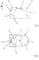
- Fig. 1 can be seen in a schematic representation of a vacuum cleaner 1 according to the invention, in the embodiment of a Zyklonabscheidstaubsaugers.
- the vacuum cleaner 1 has a vacuum cleaner body 2, which has a handle 3 and a Saugschlauchan gleich 4 in a conventional manner.
- the vacuum cleaner body 2 also provides a receptacle 5, in which a dust collection device 6 is used in the normal operating condition.
- the dust collecting device 6 has a dust collecting container 7 as well as a cyclone separator 8, which is not shown in greater detail in the figures.
- the dust collector 6 is the user side of the receptacle 5 from time to time refer to, in particular for emptying the dust collector 7, in which accumulates in the normal operation of the vacuum cleaner 1 recorded dust.
- this handle part For the purpose of removal and handling of the dust collecting device 6, this has a handle part, which is to be taken on the user side in case of need.
- this handle part provides a handle 10 and, on the other hand, two legs 11 arranged thereon, which are guided linearly in corresponding guide channels of the dust collecting device, so that the handle part 9 can be moved linearly overall in the removal direction 12 of the dust collecting device 6.
- the Figures 1 and 2 let recognize the vacuum cleaner 1 in the operating position, that is, the dust collection device 6 is taken as intended by the receptacle 5 of the vacuum cleaner body 2 and the handle part 9 is in its retracted position, in which the handle 10 flush with the upper part of the dust collecting device 10 completes.
- the dust collecting device 6 is positively received by the receptacle 5, in all six spatial directions, that is, with respect to the plane of the drawing Fig. 1 up and down and left and right as well as with reference to the drawing plane Fig. 2 up and down.
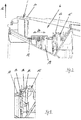
- the dust collecting device 6 has, as can be seen in particular from FIGS. 3 and 4, via a latching element 13.
- This latching element provides a latching cam 14 which engages behind a web 16 of an abutment 15 in the closed position, which abutment 15 is provided by the vacuum cleaner base body 2. Because of this gripping a positive fixing of the dust collecting device 6 is achieved relative to the vacuum cleaner body 2, and a moving out of the dust collector 6 from the exception 5 in the withdrawal direction 12 is not readily, which means unintentionally possible.
- the locking element 13 In the operating position of the vacuum cleaner 1, the locking element 13 is fixed in position in the blocking position. This is achieved by means of a locking member 17 arranged on the locking element 17, which acts on the locking element 13 with the interposition of a thrust element 18, as can be seen in particular from the perspective view schematically Fig. 5 results.
- the thrust element 18 is guided linearly by a bearing block 19, and can with respect to the drawing plane to Fig. 5 in the longitudinal direction 20 of the pusher 18 move linearly. It acts on one end with the handle part-side blocking element 17 and the other end with the locking unit 13 of the dust collecting device 6 together.
- a user For the purpose of removing the dust collecting device 6, a user has to grasp the gripping part 9 and move in the removal direction 12, as described with reference to FIG FIGS. 6 and 8th is shown by way of example.
- the moved position of the handle part 9 and the locking member 17 provided by the handle part 9 in the vertical direction that is moved in the removal direction 12 upwards.
- the pusher 18 is no longer blocked and may migrate to the left with respect to the plane of the drawing according to the figures, for example, 6 and 8.
- the locking element 13 is under spring bias in its blocking position in accordance with, for example, the Fig. 5 held.
- the latching element 13 can spring-induced with respect to the plane of the drawing Fig. 7 Move to the left, because a deflection of the thrust element 18 is possible.
- the latching element 13 is thus spring force due to no longer blocked in its thrust element in his Fig. 7 shown released position in which the positive connection between locking element 13 and abutment 15 is repealed.
- the dust collecting device 6 can now be moved in removal direction 12 from the exception 5 user side.
- the particular advantage of the above-described construction is that one-handed operation for removing the dust collecting device 6 is made possible, and this with simultaneous positive fixing of the dust collecting device 6 in the receptacle 5 in the operating position of the vacuum cleaner. 1
- FIGS. 3 to 8 show the embodiment of blocking element 17, thrust element 18 and locking element 13 with respect to a longitudinal side of the vacuum cleaner 1.
- the other longitudinal side of the vacuum cleaner 1 is formed in a corresponding manner, so that a 2-point-shaped fixing of the dust collection device 6 is ensured in case of operation.
Landscapes
- Engineering & Computer Science (AREA)
- Mechanical Engineering (AREA)
- Electric Suction Cleaners (AREA)
Abstract
Description
- Die Erfindung betrifft einen Staubsauger, insbesondere einen Zyklonabscheidestaubsauger, mit einem Staubsaugergrundkörper und einer in einer vom Staubsaugergrundkörper bereitgestellten Aufnahmen entnehmbar angeordneten Staubsammeleinrichtung, die ein Rastelement aufweist, das bei einer bestimmungsgemäß in die Aufnahme des Staubsaugergrundkörpers eingesetzten Staubsammeleinrichtung ein vom Staubsaugergrundkörper bereitgestelltes Widerlager hintergreift, so dass die Staubsammeleinrichtung in Entnahmerichtung lagegesichert ist, und mit einem in Entnahmerichtung der Staubsammeleinrichtung verfahrbar an der Staubsammeleinrichtung angeordneten Griffteil.
- Staubsauger im Allgemeinen sowie in Zyklonabscheidestaubsauger im Speziellen sind aus dem Stand der Technik an sich bekannt, weshalb es eines gesonderten druckschriftlichen Nachweises an dieser Stelle nicht bedarf.
- Bei einem Zyklonabscheidestaubsauger handelt es sich um einen sogenannten beutellosen Staubsauger. Dieser verfügt über einen Fliehkraftabscheider, das heißt einen sogenannten Zyklonabscheider, in dem im Betriebsfall eine Abscheidung der vom Saugluftstrom mitgeführten Schmutzpartikel unter Fliehkrafteinwirkung stattfindet.
- Ein gattungsgemäßer Staubsauger verfügt über einen Staubsaugergrundkörper. Dieser Staubsaugergrundkörper stellt einen Aufnahme bereit, in die eine Staubsammeleinrichtung vom Verwender des Staubsaugers entnehmbar angeordnet ist.
- Die Staubsammeleinrichtung verfügt zwecks Lagesicherung in der Aufnahme des Staubsaugergrundkörpers über ein Rastelement. Dabei hintergreift das Rastelement bei einer bestimmungsgemäß in die Aufnahme des Staubsaugergrundkörpers eingesetzten Staubsammeleinrichtung ein vom Staubsaugergrundkörper bereitgestelltes Widerlager. Auf diese Weise ist sichergestellt, dass die Staubsammeleinrichtung in Entnahmerichtung lagegesichert ist.
- Die vom Staubsaugergrundkörper bereitgestellte Aufnahme zur Anordnung der Staubsammeleinrichtung ist bei aus dem Stand der Technik vorbekannten Staubsaugern derart ausgebildet, dass die Staubsammeleinrichtung im bestimmungsgemäßen Betriebsfall des Staubsaugers in den fünf von der Entnahmerichtung abweichenden Bewegungsrichtungen formschlüssig und in Entnahmerichtung kraftschlüssig durch das Rastelement gehalten ist. Dabei sind das Rastelement und das damit zusammenwirkende Widerlager derart aufeinander abgestimmt, dass die aufgrund des Anliegens des Rastelements am Widerlager bestehende Rückhaltekraft geringer als die auf den Staubsauger einwirkende Gewichtskraft ist, so dass eine bestimmungsgemäße Entnahme der Staubsammeleinrichtung aus der vom Staubsaugergrundkörper bereitgestellten Aufnahme nicht dazu führen kann, dass der Staubsauger vom Untergrund abhebt.
- Zum Zwecke einer vereinfachten Handhabung verfügt die Staubsammeleinrichtung über ein Griffteil, das im Bedarfsfall verwenderseitig zu ergreifen ist. Das Griffteil ist linear verschieblich an der Staubsammeleinrichtung angeordnet, und zwar in Entnahmerichtung der Staubsammeleinrichtung beziehungsweise in hierzu entgegengesetzter Richtung.
- Obgleich sich vorbekannte Staubsauger im alltäglichen Praxiseinsatz bewährt haben, besteht Verbesserungsbedarf, insbesondere hinsichtlich der Handhabung einer aus der Aufnahme des Staubsaugergrundkörpers verwenderseitig zu entnehmenden Staubsammeleinrichtung. So hat sich gezeigt, dass die allein kraftschlüssige Festlegung der Staubsammeleinrichtung in Entnahmerichtung bei einer insbesondere unsachgemäßen Handhabung des Staubsaugers dazu führen kann, dass sich die Staubsammeleinrichtung in unerwünschter Weisung aus der Aufnahme des Staubsaugergrundkörpers hinausbewegt. Um diesem Problem zu begegnen, ist es aus dem Stand der Technik bekannt, eine formschlüssige Verriegelung der Staubsammeleinrichtung auch in Entnahmerichtung derselben vorzusehen. Eine solche Verriegelung macht im Entnahmefall jedoch in nachteiliger Weise eine Zweihandbetätigung erforderlich. So ist einerseits eine Entriegelung vorzunehmen sowie andererseits das Griffteil der Staubsammeleinrichtung zu ergreifen, um die Staubsammeleinrichtung aus der Aufnahme des Staubsaugergrundkörpers hinaus zu führen. Eine solche Zweihandbetätigung wird verwenderseitig als umständlich empfunden und verkompliziert eine Entnahme der Staubsammeleinrichtung in unnötiger Weise. Zudem bedarf es zur Ausbildung einer solchen Verriegelung zusätzliche Bauteile, was die Herstellung des Staubsaugers verteuert.
- Ausgehend vom Vorbeschriebenen ist es die Aufgabe der Erfindung, einen Staubsauger der gattungsgemäßen Art dahingehend weiterzuentwickeln, dass eine verwenderseitige Entnahme der Staubsammeleinrichtung in einfacher Weise gestattet ist, und dies bei gleichzeitiger Gewährleistung einer Lagesicherung der Staubsammeleinrichtung in der vom Staubsaugergrundkörper bereitgestellten Aufnahme.
- Zur Lösung dieser Aufgabe wird mit der Erfindung ein Staubsauger der eingangs genannten Art vorgeschlagen, der sich dadurch auszeichnet, dass das Rastelement aus einer Freigabestellung in eine Sperrstellung und umgekehrt überführbar ist, wobei das Rastelement mit einem vom Griffteil bereitgestellten Sperrelement zusammenwirkt, das bei in Entnahmerichtung der Staubsammeleinrichtung verfahrenem Griffteil eine Überführung des Rastelements aus der Sperrstellung in die Freigabestellung freigibt.
- Die erfindungsgemäße Konstruktion sieht ein Sperrelement vor. Dieses Sperrelement wirkt mit dem Rastelement zusammen, wobei das Sperrelement je nach Stellung eine Verfahrbewegung des Rastelements blockiert oder freigibt. Auf diese Weise ist erreicht, dass das Rastelement mittels des Sperrelements in seiner Sperrstellung mit der Folge gehalten werden kann, dass in Entnahmerichtung der Staubsammeleinrichtung nicht nur ein kraftschlüssiges, sondern auch ein formschlüssiges Festlegen der Staubsammeleinrichtung relativ gegenüber der vom Staubsaugergrundkörper bereitgestellten Aufnahme gewährleistet ist. Dies erbringt den Vorteil, dass die Staubsammeleinrichtung auch bei einer unsachgemäßen Handhabung des Staubsaugers sicher in ihrer Lage fixiert ist und ein unerwünschtes Herausgleiten der Staubsammeleinrichtung aus der Aufnahme des Staubsaugergrundkörpers sicher vermieden ist.
- Sobald das Rastelement aus seiner Sperrstelllung in seine Freigabestellung überführt ist, kann die Staubsammeleinrichtung verwenderseitig der vom Staubsaugergrundkörper bereitgestellten Aufnahme bestimmungsgemäß entnommen werden. Eine solche Entnahme ist indes dann nicht möglich, wenn sich das Rastelement in seiner Sperrstellung befindet. In dieser Stellung hintergreift das Rastelement das vom Staubsaugergrundkörper bereitgestellte Widerlager, womit ein entsprechender Formschluss gegeben ist, der eine Entnahme der Staubsammeleinrichtung blockiert. Ein ungewolltes Verfahren des Rastelements aus seiner Sperrstellung in seine Freigabestellung ist durch das erfindungsgemäße Sperrelement realisiert. Denn auch das Sperrelement kann sich entweder in einer Sperrstellung oder in einer Freigabestellung befinden, wobei das Sperrelement im Falle seiner Sperrstellung das Rastelement blockiert, so dass das Rastelemente die Staubsammeleinrichtung nicht freigeben kann. Erst wenn das Sperrelement seinerseits in die Freigabestellung überführt ist, kann auch das Rastelement aus seiner Sperrstellung in seine Freigabestellung überführt werden, was dann eine Entnahme der Staubsammeleinrichtung in Entnahmerichtung gestattet.
- Das Sperrelement ist erfindungsgemäß am Griffteil angeordnet. Sobald das Griffteil zwecks Entnahme der Staubsammeleinrichtung ergriffen und in Entnahmerichtung verfahren wird, findet auch eine Überführung des Sperrelements aus der Sperrstellung in die Freigabestellung statt. Im Ergebnis steht, dass das Rastelement freigegeben wird, das heißt der Formschluss aufgelöst wird. Die Staubsammeleinrichtung wird dann nur noch kraftschlüssig gehalten, welcher Kraftschluss bei einem verwenderseitigen Ziehen am Griffteil der Staubsammeleinrichtung überwunden wird, womit es zur Entnahme der Staubsammeleinrichtung kommt.
- Die konstruktive Besonderheit nach der Erfindung bringt den Vorteil, dass eine einhändige Bedienung gestattet ist, und dies bei gleichzeitiger Sicherung der Staubsammeleinrichtung im bestimmungsgemäßen Betriebsfall durch Formschluss. Denn solange sich das Griffteil in nicht verfahrener Stellung befindet, wirkt das am Griffteil angeordnete Sperrelement mit dem Rastelement zusammen, womit das Rastelement in seiner Sperrstellung formschlüssig das vom Staubsaugergrundkörper bereitgestellte Widerlager hintergreift. Ein unbeabsichtigtes Hinausbewegen der Staubsammeleinrichtung aus der Aufnahme des Staubsaugergrundkörpers ist so sicher unterbunden. Soll die Staubsammeleinrichtung der Aufnahme des Staubsaugergrundkörpers nun entnommen werden, beispielsweise Zwecks Entleerung derselben, so ist das Griffteil der Staubsammeleinrichtung verwenderseitig zu ergreifen und in Entnahmerichtung zu verfahren. Infolge dieses Verfahrens wird die Wirkverbindung zwischen dem vom Griffteil bereitgestellten Sperrelement einerseits und dem Rastelement andererseits aufgehoben. Damit ist eine Überprüfung des Rastelements aus der Sperrstellung in die Freigabestellung freigegeben. Es liegt mithin nur noch eine kraftschlüssige, nicht mehr aber eine formschlüssige Verbindung zwischen dem Rastelement und dem Widerlager vor. Wird nun verwenderseitig unter entsprechender Kraftaufbringung am Griffteil gezogen, so löst sich die Staubsammeleinrichtung unter Überwindung der kraftschlüssigen Verbindung zwischen Rastelement und Widerlager aus der Aufnahme des Staubsaugergrundkörpers, womit eine bestimmungsgemäße Entnahme der Staubsammeleinrichtung in Entnahmerichtung stattfindet.
- Im Ergebnis der erfindungsgemäßen Konstruktion steht, dass eine einfache und vor allem einhändige Bedienung gestattet ist, im Unterschied zum Stand der Technik also nicht separat zu bedienende Entriegelungstasten vorgesehen sind, und dass im bestimmungsgemäßen Betriebsfall des Staubsaugers die Staubsammeleinrichtung auch in Entnahmerichtung formschlüssig in der Aufnahme des Staubsaugergrundkörpers gehalten ist, so dass selbst bei einer unsachgemäßen Handhabung des Staubsaugers ein unerwünschtes Herausbewegen der Staubsammeleinrichtung aus der Aufnahme sicher versperrt ist.
- Es ist gemäß einem weiteren Merkmal der Erfindung vorgesehen, dass bei unverfahrenem Griffteil eine Überführung des Rastelements aus der Sperrstellung in die Freigabestellung mittels des Sperrelements gesperrt ist. Bei unverfahrenem Griffteil ist mithin die formschlüssige Verbindung zwischen Rastelement einerseits und staubsaugergrundkörperseitigem Widerlager andererseits festgesetzt. Das Rastelement kann zur Auflösung dieser formschlüssigen Verbindung nicht verfahren, denn es ist durch das Sperrelement in seiner Verfahrbewegung blockiert. Erst wenn das Griffteil vom Verwender ergriffen und in Entnahmerichtung der Staubsaugereinrichtung verfahren ist, ist das Sperrelement außer Eingriff mit dem Rastelement gebracht, was dann ein Verfahren des Rastelements in die Freigabestellung ermöglicht, womit die formschlüssige Verbindung zwischen Rastelement und Widerlager durch kraftinduziertes Zurückverfahren des Rastelements aufgehoben werden kann.
- Gemäß einer besonderen Ausgestaltung der Erfindung stehen das Sperrelement und das Rastelement nicht direkt in Wirkverbindung, sondern mittelbar unter Zwischenordnung eines Schubelements. Bei diesem Schubelement kann es sich beispielsweise um eine Schubstange handeln, die einendseitig mit dem Sperrelement und anderendseitig mit dem Rastelemente direkt zusammenwirkt. Sofern sich das Sperrelement in seiner Sperrstellung befindet, blockiert es das Schubelement in seiner Verfahrbewegung. Damit ist auch das Rastelement in seiner Verfahrbewegung blockiert. Sobald das Sperrelement in seine Freigabestellung überführt ist, kann auch das Schubelement verfahren, das heißt es ist durch das Sperrelement nicht weiter blockiert. Kommt es nun zu einer kraftinduzierten Überführung des Rastelements aus seiner Sperrstellung in seine Freigabestellung, so erfolgt dies unter gleichzeitiger Verschiebebewegung des Schubelements, welche Bewegung deshalb möglich ist, weil sich das Sperrelement in seiner Freigabestellung befindet und das Schubelement nicht weiter blockiert. Insofern wirkt das Schubelement als Kraftübertragungsglied zwischen Sperrelement einerseits und Rastelement andererseits.
- Gemäß einem weiteren Merkmal der Erfindung ist vorgesehen, dass das Rastelement in Sperrstellung unter Federvorspannung gehalten ist. Diese Ausgestaltung hat den Vorteil, dass das Rastelement automatisch aus seiner Sperrstellung in seine Freigabestellung federkraftinduziert überführt wird, sobald das Sperrelement das Rastelement freigibt, das Rastelement also aufgrund des in seine Freigabestellung überführten Sperrelements nicht weiter blockiert ist und deshalb in seine Freigabestellung überführt werden kann.
- Grundsätzlich sind in diesem Zusammenhang zwei Ausführungsalternativen denkbar. Gemäß einer ersten Alternative wird das Rastelement unter Federvorspannung in Freigabestellung gehalten. Gemäß dieser Variante bleibt auch nach einem in seine Freigabestellung überführtem Sperrelement der Formschluss zwischen Rastelement und Widerlager bestehen. Dies deshalb, weil das Rastelement federkraftinduziert in den vom Widerlager bereitgestellten Hinterschnitt nach wie vor eingreift. Wird nun verwenderseitig die Staubsammeleinrichtung der Aufnahme des Staubsaugergrundkörpers bestimmungsgemäß entnommen, so geschieht dies durch verwenderseitig eingebrachte Krafteinwirkung. Dabei ist die verwenderseitig aufzubringende Kraft zumindest so groß, dass die das Rastelement in Verschlussstellung haltende Federkraft überwunden wird. Bei einer Entnahme der Staubsammeleinrichtung federt das Rastelement entgegen der auf das Rastelement einwirkenden Federkraft in die Freigabestellung, was dann eine Entnahme der Staubsammeleinrichtung möglich macht. Gemäß dieser Alternative hat die Entnahme der Staubsammeleinrichtung unter einer gewissen Kraftaufwendung zu erfolgen, die sich in Abhängigkeit der zu überwindenden und auf das Rastelement einwirkenden Federkraft ergibt.
- Gemäß einer zweiten Alternative ist das Rastelement in schon vorbeschriebener Weise nicht in Freigabestellung sondern in Sperrstellung unter Federvorspannung gehalten. Gemäß dieser Ausführungsform federt das Rastelement aufgrund der auf das Rastelement einwirkenden Federkraft also automatisch dann aus seiner Sperrstellung in die Freigabestellung zurück, wenn das Sperrelement aus der Wirkverbindung mit dem Rastelement tritt, sei es, dass das Sperrelement direkt mit dem Rastelement oder unter Zwischenschaltung eines Schubelements mit dem Rastelement zusammenwirkt. Gemäß dieser Alternative bewirkt also bereits die Überführung des Sperrelements in die Freigabestellung, dass sich auch das Rastelement aus seiner Sperrstellung in die Freigabestellung begibt, so dass in Entnahmerichtung der Staubsammeleinrichtung weder eine kraftschlüssige, noch eine formschlüssige Verbindung zum Widerlager des Staubsaugergrundkörpers gegeben ist.
- Gemäß einem weiteren Merkmal der Erfindung ist in diesem Zusammenhang vorgesehen, dass das Rastelement bei Freigabe durch das Sperrelement federkraftinduziert in seine Freigabestellung bewegt ist. In schon vorbeschriebener Weise erfolgt also eine automatische Überführung des Rastelements aus der Sperrstellung in die Freigabestellung dann, wenn das Sperrelement in seine Freigabestellung überführt ist, und zwar federkraftinduziert, das heißt aufgrund der auf das Rastelement in Sperrstellung einwirkenden Federvorspannung.
- Die Staubsammeleinrichtung ist bevorzugterweise eine solche eines Zyklonabscheidestaubsaugers. In diesem Fall weist die Staubsammeleinrichtung einerseits einen Staubsammelbehälter sowie andererseits einen Zyklonabscheider auf.
- Das von der Staubsammeleinrichtung bereitgestellte Griffteil ist in Entnahmerichtung der Staubsammeleinrichtung linear verfahrbar angeordnet, was konstruktiv dadurch realisiert ist, dass das Griffteil eine Handhabe einerseits sowie zwei daran angeordnete Schenkel aufweist, das Griffteil mithin nach Art eines U-förmigen Bügels ausgebildet ist. Dabei ergibt sich die lineare Verschieblichkeit des Griffteils dadurch, dass es in Längsrichtung der Schenkel relativ zur Staubsammeleinrichtung verfahren werden kann. Konstruktiv ist zu diesem Zweck vorgesehen, dass die Staubsammeleinrichtung über entsprechende Führungskanäle verfügt, in denen die Schenkel des Griffteils linear verfahrbar angeordnet sind.
- Weitere Merkmale und Vorteile der Erfindung ergeben sich aus der nachfolgenden Beschreibung anhand der Figuren.
- Dabei zeigen
- Fig. 1
- in schematischer Seitenansicht einen erfindungsgemäßen Staubsauger;
- Fig. 2
- in schematischer Draufsicht von oben den Staubsauger nach
Fig. 1 ; - Fig. 3
- in seitlicher Schnittdarstellung ausschnittsweise die Staubsammeleinrichtung in Verschlussstellung;
- Fig. 4
- in einer schematischen Detailansicht das Rastelement nach
Fig. 3 ; - Fig. 5
- in einer schematischen Perspektivdarstellung die Staubsammeleinrichtung nach
Fig. 3 ; - Fig. 6
- in seitlicher Schnittdarstellung ausschnittsweise die Staubsammeleinrichtung in entriegelter Stellung;
- Fig. 7
- in einer schematischen Detailansicht das Rastelement nach
Fig. 3 und - Fig. 8
- in einer schematischen Perspektivdarstellung die Staubsammeleinrichtung nach
Fig. 6 . -
Fig. 1 lässt in schematischer Darstellung einen Staubsauger 1 nach der Erfindung erkennen, und zwar in der Ausgestaltung eines Zyklonabscheidestaubsaugers. - Der Staubsauger 1 verfügt über einen Staubsaugergrundkörper 2, der in an sich bekannter Weise über eine Handhabe 3 und einen Saugschlauchanschluss 4 verfügt.
- Der Staubsaugergrundkörper 2 stellt desweiteren eine Aufnahme 5 bereit, in die im bestimmungsgemäßen Betriebsfall eine Staubsammeleinrichtung 6 eingesetzt ist. Im gezeigten Ausführungsbeispiel verfügt die Staubsammeleinrichtung 6 über einen Staubsammelbehälter 7 sowie über einen in den Figuren nicht näher dargestellten Zyklonabscheider 8.
- Die Staubsammeleinrichtung 6 ist verwenderseitig der Aufnahme 5 von Zeit zu Zeit zu entnehmen, insbesondere zur Entleerung des Staubsammelbehälters 7, in dem sich im bestimmungsgemäßen Betriebsfall vom Staubsauger 1 aufgenommener Staub ansammelt.
- Zwecks Entnahme und Handhabung der Staubsammeleinrichtung 6 verfügt diese über ein Griffteil, die im Bedarfsfall verwenderseitig zu ergreifen ist. Diese Griffteil stellt einerseits eine Handhabe 10 sowie andererseits zwei daran angeordnete Schenkel 11 bereit, die in entsprechenden Führungskanälen der Staubsammeleinrichtung linear geführt sind, so dass das Griffteil 9 insgesamt in Entnahmerichtung 12 der Staubsammeleinrichtung 6 linear verfahren werden kann.
- Die
Figuren 1 und 2 lassen den Staubsauger 1 in Betriebsstellung erkennen, das heißt die Staubsammeleinrichtung 6 ist bestimmungsgemäß von der Aufnahme 5 des Staubsaugergrundkörpers 2 aufgenommen und das Griffteil 9 befindet sich in seiner eingefahrenen Stellung, in welcher die Handhabe 10 oberflächenbündig mit dem Oberteil der Staubsammeleinrichtung 10 abschließt. In dieser Stellung der Staubsammeleinrichtung 6 ist die Staubsammeleinrichtung 6 formschlüssig von der Aufnahme 5 aufgenommen, und zwar in allen sechs Raumrichtungen, das heißt mit Bezug auf die Zeichnungsebene nachFig. 1 nach oben und unten sowie links und rechts sowie mit Bezug auf die Zeichnungsebene nachFig. 2 nach oben und unten. - Es findet mithin in Betriebsstellung auch eine formschlüssige Festlegung der Staubsammeleinrichtung 6 in Entnahmerichtung 12 statt, wie sich im Detail aus den weiteren Figuren ergibt.
- Die Staubsammeleinrichtung 6 verfügt, wie sich insbesondere aus den Figuren beispielsweise 3 und 4 ergibt, über ein Rastelement 13. Dieses Rastelement stellt einen Rastnocken 14 bereit, der in Verschlussstellung einen Steg 16 eines Widerlagers 15 hintergreift, welches Widerlager 15 vom Staubsaugergrundkörper 2 bereitgestellt wird. Aufgrund dieses Hintergreifens ist eine formschlüssige Festlegung der Staubsammeleinrichtung 6 relativ gegenüber dem Staubsaugergrundkörper 2 erreicht, und ein Herausbewegen der Staubsammeleinrichtung 6 aus der Ausnahme 5 in Entnahmerichtung 12 ist nicht ohne weiteres, das hießt ungewollt möglich.
- In der Betriebsstellung des Staubsaugers 1 ist das Rastelement 13 in der Sperrstellung lagefixiert. Dies ist mittels eines am Griffteil 9 angeordneten Sperrelements 17 erreicht, das unter Zwischenwirkung eines Schubelements 18 auf das Rastelement 13 einwirkt, wie sich dies insbesondere aus der schematisch perspektivischen Darstellung nach
Fig. 5 ergibt. - Das Schubelement 18 ist linear von einem Lagerbock 19 geführt, und kann sich mit Bezug auf die Zeichnungsebene nach
Fig. 5 in Längsrichtung 20 des Schubelements 18 linear bewegen. Es wirkt einendseitig mit dem griffteilseitigen Sperrelement 17 und anderendseitig mit der Rasteinheit 13 der Staubsammeleinrichtung 6 zusammen. - In Betriebsstellung des Staubsaugers in Entsprechung der
Figuren 1 und 2 befindet sich das Griffteil in herunterverfahrener Stellung, wie sich insbesondere aus den Darstellungen nachFig. 3 und5 ergibt. In dieser Stellung des Griffteils 9 wirkt das vom Griffteil 9 bereitgestellte Sperrelement 17 einendseitig mit dem Schubelement 18 mit der Folge zusammen, dass das Schubelement 18 in seiner linearen Bewegungsfreiheit mit Bezug auf die Zeichnungsebene nachFig. 5 nach links blockiert ist. Dies führt dazu, dass auch das Rastelement 13 nicht mit Bezug auf die Zeichnungsebene nach denFiguren 4 und5 nicht nach links ausweichen und in seine Freigabestellung überführt werden kann, so dass der vom Rastelement 13 bereitgestellte Rastnocken 14 im Hinterschnitt mit dem Widerlager 15 verbleibt. Es ist infolgedessen eine formschlüssige Verbindung zwischen Staubsammeleinrichtung 6 und Staubsaugergrundkörper 2 in Entnahmerichtung 12 realisiert, so dass die Staubsammeleinrichtung 6 in Entnahmerichtung 12 nicht ungewollt aus der Aufnahme 5 herausbewegt werden kann. - Zwecks Entnahme der Staubsammeleinrichtung 6 hat ein Verwender das Griffteil 9 zu ergreifen und in Entnahmerichtung 12 zu verfahren, wie dies anhand der
Figuren 6 und8 beispielshaft dargestellt ist. In der verfahrenen Stellung des Griffteils 9 ist auch das vom Griffteil 9 bereitgestellte Sperrelement 17 in Höhenrichtung, das heißt in Entnahmerichtung 12 nach oben verfahren. Infolgedessen ist das Schubelement 18 nicht mehr blockiert und kann mit Bezug auf die Zeichnungsebene nach den Figuren beispielsweise 6 und 8 nach links auswandern. - Das Rastelement 13 wird unter Federvorspannung in seiner Sperrstellung in Entsprechung beispielsweise der
Fig. 5 gehalten. Sobald nun das Schubelement 18 durch das Sperrelement 17 nicht mehr blockiert ist, kann das Rastelement 13 federkraftinduziert mit Bezug auf die Zeichnungsebene nachFig. 7 nach links verfahren, denn ist ein Ausweichen des Schubelements 18 ermöglicht. Das Rastelement 13 wird also bei nicht mehr blockiertem Schubelement 18 federkraftbedingt in seine inFig. 7 gezeigte Freigabestellung überführt, in welcher die formschlüssige Verbindung zwischen Rastelement 13 und Widerlager 15 aufgehoben ist. Die Staubsammeleinrichtung 6 kann nunmehr in Entnahmerichtung 12 aus der Ausnahme 5 verwenderseitig bewegt werden. - Ein Einsetzen der Staubsammeleinrichtung 6 in die Aufnahme 5 erfolgt in umgekehrter Reihenfolge. Entgegen der Entnahmerichtung 12 wird die Staubsammeleinrichtung 6 in die Aufnahme 5 eingesetzt und das Griffteil 9 wird entgegen der Entnahmerichtung 12 nach unten verfahren. Dabei drückt sich die vom Sperrelement 17 bereitgestellte Rampe einendseitig an das Schubelement 9, wodurch dieses mit Bezug auf die Zeichnungsebene nach
Fig. 8 nach rechts verfahren wird, so dass es gegen das Rastelement 13 drückt. Entgegen der auf das Rastelement 13 wirkenden Federkraft wird das Rastelement 13 verfahren, und zwar soweit, bis der vom Rastelement 13 bereitgestellte Rastnocken 14 in schon vorbeschriebener Weise das von dem Staubsaugergrundkörper 2 bereitgestellte Widerlager 15 hintergreift. Es ist nun wieder ein formschlüssiger Kontakt zwischen Rastelement 13 und Widerlager 15 ausgebildet, der ein ungewolltes Herausbewegen der Staubsammeleinrichtung 6 aus der Aufnahme 5 verhindert. - Der besondere Vorteil der vorbeschriebenen Konstruktion liegt darin, dass eine einhändige Bedienung zur Entnahme der Staubsammeleinrichtung 6 ermöglicht ist, und dies bei gleichzeitig formschlüssiger Festlegung der Staubsammeleinrichtung 6 in der Aufnahme 5 in Betriebsstellung des Staubsaugers 1.
- Die
Figuren 3 bis 8 zeigen die Ausgestaltung von Sperrelement 17, Schubelement 18 und Rastelement 13 mit Bezug auf eine Längsseite des Staubsaugers 1. Die andere Längsseite des Staubsaugers 1 ist in entsprechender Weise ausgebildet, so dass eine 2-Punkt-förmige Festlegung der Staubsammeleinrichtung 6 im Betriebsfall sichergestellt ist. -
- 1
- Staubsauger
- 2
- Staubsaugergrundkörper
- 3
- Handhabe
- 4
- Saugschlauchanschluss
- 5
- Aufnahme
- 6
- Staubsammeleinrichtung
- 7
- Staubsammelbehälter
- 8
- Zyklonabscheider
- 9
- Griffteil
- 10
- Handhabe
- 11
- Schenkel
- 12
- Entnahmerichtung
- 13
- Rastelement
- 14
- Rastnocken
- 15
- Widerlager
- 16
- Steg
- 17
- Sperrelement
- 18
- Schubelement
- 19
- Lagerbock
- 20
- Längsrichtung
Claims (7)
- Staubsauger, insbesondere Zyklonabscheidestaubsauger, mit einem Staubsaugergrundkörper (2) und einer in einer vom Staubsaugergrundkörper (2) bereitgestellten Aufnahme (5) entnehmbar angeordneten Staubsammeleinrichtung (6), die ein Rastelement (13) aufweist, das bei einer bestimmungsgemäß in die Aufnahme (5) des Staubsaugergrundkörpers (2) eingesetzten Staubsammeleinrichtung (6) ein vom Staubsaugergrundkörper (2) bereitgestelltes Widerlager (15) hintergreift, so dass die Staubsammeleinrichtung (6) in Entnahmerichtung (12) lagegesichert ist, und mit einem in Entnahmerichtung (12) der Staubsammeleinrichtung (6) verfahrbar an der Staubsammeleinrichtung (6) angeordneten Griffteil (9),
dadurch gekennzeichnet,
dass das Rastelement (13) aus einer Freigabestellung in eine Sperrstellung und umgekehrt überführbar ist, wobei das Rastelement (13) mit einem vom Griffteil (9) bereitgestellten Sperrelement (17) zusammenwirkt, das bei in Entnahmerichtung (12) der Staubsammeleinrichtung (6) verfahrenem Griffteil (9) eine Überführung des Rastelements aus der Sperrstellung in die Freigabestellung freigibt. - Staubsauger nach Anspruch 1, dadurch gekennzeichnet, dass bei unverfahrenem Griffteil (9) eine Überführung des Rastelements (13) aus der Sperrstellung in die Freigabestellung mittels des Sperrelements (17) gesperrt ist.
- Staubsauger nach Anspruch 1 oder 2, dadurch gekennzeichnet, dass das Sperrelement (17) unter Zwischenordnung eines Schubelements (18) auf das Rastelement (13) einwirkt.
- Staubsauger nach einem der vorhergehenden Ansprüche, dadurch gekennzeichnet, dass das Rastelement (13) in Sperrstellung unter Federvorspannung gehalten ist.
- Staubsauger nach Anspruch 4, dadurch gekennzeichnet, dass das Rastelement (13) bei Freigabe durch das Sperrelement (17) federkraftinduziert in seine Freigabestellung bewegt ist.
- Staubsauger nach einem der vorhergehenden Ansprüche, dadurch gekennzeichnet, dass die Staubsammeleinrichtung (6) einen Zyklonabscheider (8) sowie einen Staubsammelbehälter (7) aufweist.
- Staubsauger nach einem der vorhergehenden Ansprüche, dadurch gekennzeichnet, dass das Griffteil (9) eine Handhabe (10) sowie zwei daran angeordnete Schenkel (11) aufweist.
Applications Claiming Priority (1)
| Application Number | Priority Date | Filing Date | Title |
|---|---|---|---|
| DE102016110520.1A DE102016110520A1 (de) | 2016-06-08 | 2016-06-08 | Staubsauger, insbesondere Zyklonabscheidestaubsauger |
Publications (2)
| Publication Number | Publication Date |
|---|---|
| EP3254592A1 true EP3254592A1 (de) | 2017-12-13 |
| EP3254592B1 EP3254592B1 (de) | 2021-10-06 |
Family
ID=58701504
Family Applications (1)
| Application Number | Title | Priority Date | Filing Date |
|---|---|---|---|
| EP17170533.8A Active EP3254592B1 (de) | 2016-06-08 | 2017-05-11 | Staubsauger, insbesondere zyklonabscheidestaubsauger |
Country Status (2)
| Country | Link |
|---|---|
| EP (1) | EP3254592B1 (de) |
| DE (1) | DE102016110520A1 (de) |
Citations (4)
| Publication number | Priority date | Publication date | Assignee | Title |
|---|---|---|---|---|
| US20060123588A1 (en) * | 2002-12-30 | 2006-06-15 | Helmut Kaiser | Vacuum cleaner comprising a filter drawer |
| JP2007117710A (ja) * | 2005-10-28 | 2007-05-17 | Samsung Kwangju Electronics Co Ltd | 真空掃除機 |
| DE102007008915B3 (de) * | 2007-02-23 | 2008-06-12 | BSH Bosch und Siemens Hausgeräte GmbH | Staubsauger mit entnehmbarem Staubsammelbehälter |
| EP2677914B1 (de) * | 2011-02-22 | 2016-11-02 | Aktiebolaget Electrolux | Staubsauger |
-
2016
- 2016-06-08 DE DE102016110520.1A patent/DE102016110520A1/de not_active Withdrawn
-
2017
- 2017-05-11 EP EP17170533.8A patent/EP3254592B1/de active Active
Patent Citations (4)
| Publication number | Priority date | Publication date | Assignee | Title |
|---|---|---|---|---|
| US20060123588A1 (en) * | 2002-12-30 | 2006-06-15 | Helmut Kaiser | Vacuum cleaner comprising a filter drawer |
| JP2007117710A (ja) * | 2005-10-28 | 2007-05-17 | Samsung Kwangju Electronics Co Ltd | 真空掃除機 |
| DE102007008915B3 (de) * | 2007-02-23 | 2008-06-12 | BSH Bosch und Siemens Hausgeräte GmbH | Staubsauger mit entnehmbarem Staubsammelbehälter |
| EP2677914B1 (de) * | 2011-02-22 | 2016-11-02 | Aktiebolaget Electrolux | Staubsauger |
Also Published As
| Publication number | Publication date |
|---|---|
| DE102016110520A1 (de) | 2017-12-14 |
| EP3254592B1 (de) | 2021-10-06 |
Similar Documents
| Publication | Publication Date | Title |
|---|---|---|
| EP3670102A1 (de) | Stapelbarer koffer, anordnung mit zwei übereinander gestappelten koffern und verwendung eines koffers | |
| DE202011052524U1 (de) | Interlock-Baugruppe für eine Auszugsschiene | |
| DE10206854C1 (de) | Ausziehsperre für übereinander angeordnete Schubladen | |
| DE102008055043A1 (de) | Multifunktionsdüse für Staubsauger | |
| EP1761731B1 (de) | Linearführungssystem für einen auszug | |
| DE102012109751A1 (de) | Auszugführung eines ausziehbaren Möbelteils und Möbel | |
| DE102012100042A1 (de) | Akkutischsauger mit einem abnehmbaren Staubsammelbehälter | |
| EP0553482B1 (de) | Teleskopierbares Staubsauger-Saugrohr | |
| DE202010016160U1 (de) | Teleskoprohr für Staubsauger | |
| EP0804698B1 (de) | Griff für eine sanitärarmatur | |
| EP3254592B1 (de) | Staubsauger, insbesondere zyklonabscheidestaubsauger | |
| EP2459045B1 (de) | Staubsauger mit staubbehälter | |
| EP3603899A1 (de) | Schnittstelle für akkupack | |
| DE202019102375U1 (de) | Magazin-Schnellladungseinrichtung | |
| DE102015114596B4 (de) | Werkzeugschrank | |
| EP2459044B1 (de) | Staubsauger mit verriegelungseinheit | |
| DE102015106645A1 (de) | Staubsauger sowie Staubabscheidebehälter für einen Staubsauger | |
| EP2659819B1 (de) | Staubsauger | |
| EP2078592B1 (de) | Werkzeugstiel zur Anbringung an einem Werkzeuggriff | |
| EP3050476B1 (de) | Zyklonabscheidestaubsauger | |
| DE102014209954A1 (de) | Filtervorrichtung für Dunstabzugshaube und Dunstabzugshaube | |
| DE202013008659U1 (de) | Höhenverstellbare Anhängerkupplung | |
| WO2010043244A1 (de) | Verriegelungsvorrichtung | |
| WO1986003022A1 (fr) | Dispositif de reclassement cyclique d'une pile de feuilles rectangulaires ou carrees | |
| DE202008013836U1 (de) | Verschiebbare, positionierbare Schubladen-Rückstellvorrichtung |
Legal Events
| Date | Code | Title | Description |
|---|---|---|---|
| PUAI | Public reference made under article 153(3) epc to a published international application that has entered the european phase |
Free format text: ORIGINAL CODE: 0009012 |
|
| STAA | Information on the status of an ep patent application or granted ep patent |
Free format text: STATUS: THE APPLICATION HAS BEEN PUBLISHED |
|
| STAA | Information on the status of an ep patent application or granted ep patent |
Free format text: STATUS: REQUEST FOR EXAMINATION WAS MADE |
|
| AK | Designated contracting states |
Kind code of ref document: A1 Designated state(s): AL AT BE BG CH CY CZ DE DK EE ES FI FR GB GR HR HU IE IS IT LI LT LU LV MC MK MT NL NO PL PT RO RS SE SI SK SM TR |
|
| AX | Request for extension of the european patent |
Extension state: BA ME |
|
| 17P | Request for examination filed |
Effective date: 20171108 |
|
| RBV | Designated contracting states (corrected) |
Designated state(s): AL AT BE BG CH CY CZ DE DK EE ES FI FR GB GR HR HU IE IS IT LI LT LU LV MC MK MT NL NO PL PT RO RS SE SI SK SM TR |
|
| GRAP | Despatch of communication of intention to grant a patent |
Free format text: ORIGINAL CODE: EPIDOSNIGR1 |
|
| STAA | Information on the status of an ep patent application or granted ep patent |
Free format text: STATUS: GRANT OF PATENT IS INTENDED |
|
| INTG | Intention to grant announced |
Effective date: 20210602 |
|
| GRAS | Grant fee paid |
Free format text: ORIGINAL CODE: EPIDOSNIGR3 |
|
| GRAA | (expected) grant |
Free format text: ORIGINAL CODE: 0009210 |
|
| STAA | Information on the status of an ep patent application or granted ep patent |
Free format text: STATUS: THE PATENT HAS BEEN GRANTED |
|
| REG | Reference to a national code |
Ref country code: DE Ref legal event code: R084 Ref document number: 502017011641 Country of ref document: DE |
|
| AK | Designated contracting states |
Kind code of ref document: B1 Designated state(s): AL AT BE BG CH CY CZ DE DK EE ES FI FR GB GR HR HU IE IS IT LI LT LU LV MC MK MT NL NO PL PT RO RS SE SI SK SM TR |
|
| REG | Reference to a national code |
Ref country code: GB Ref legal event code: FG4D Free format text: NOT ENGLISH |
|
| REG | Reference to a national code |
Ref country code: CH Ref legal event code: EP Ref country code: AT Ref legal event code: REF Ref document number: 1435502 Country of ref document: AT Kind code of ref document: T Effective date: 20211015 |
|
| REG | Reference to a national code |
Ref country code: IE Ref legal event code: FG4D Free format text: LANGUAGE OF EP DOCUMENT: GERMAN |
|
| REG | Reference to a national code |
Ref country code: DE Ref legal event code: R096 Ref document number: 502017011641 Country of ref document: DE |
|
| REG | Reference to a national code |
Ref country code: LT Ref legal event code: MG9D |
|
| REG | Reference to a national code |
Ref country code: NL Ref legal event code: MP Effective date: 20211006 |
|
| REG | Reference to a national code |
Ref country code: GB Ref legal event code: 746 Effective date: 20220223 |
|
| PG25 | Lapsed in a contracting state [announced via postgrant information from national office to epo] |
Ref country code: RS Free format text: LAPSE BECAUSE OF FAILURE TO SUBMIT A TRANSLATION OF THE DESCRIPTION OR TO PAY THE FEE WITHIN THE PRESCRIBED TIME-LIMIT Effective date: 20211006 Ref country code: LT Free format text: LAPSE BECAUSE OF FAILURE TO SUBMIT A TRANSLATION OF THE DESCRIPTION OR TO PAY THE FEE WITHIN THE PRESCRIBED TIME-LIMIT Effective date: 20211006 Ref country code: FI Free format text: LAPSE BECAUSE OF FAILURE TO SUBMIT A TRANSLATION OF THE DESCRIPTION OR TO PAY THE FEE WITHIN THE PRESCRIBED TIME-LIMIT Effective date: 20211006 Ref country code: BG Free format text: LAPSE BECAUSE OF FAILURE TO SUBMIT A TRANSLATION OF THE DESCRIPTION OR TO PAY THE FEE WITHIN THE PRESCRIBED TIME-LIMIT Effective date: 20220106 |
|
| PG25 | Lapsed in a contracting state [announced via postgrant information from national office to epo] |
Ref country code: IS Free format text: LAPSE BECAUSE OF FAILURE TO SUBMIT A TRANSLATION OF THE DESCRIPTION OR TO PAY THE FEE WITHIN THE PRESCRIBED TIME-LIMIT Effective date: 20220206 Ref country code: SE Free format text: LAPSE BECAUSE OF FAILURE TO SUBMIT A TRANSLATION OF THE DESCRIPTION OR TO PAY THE FEE WITHIN THE PRESCRIBED TIME-LIMIT Effective date: 20211006 Ref country code: PT Free format text: LAPSE BECAUSE OF FAILURE TO SUBMIT A TRANSLATION OF THE DESCRIPTION OR TO PAY THE FEE WITHIN THE PRESCRIBED TIME-LIMIT Effective date: 20220207 Ref country code: PL Free format text: LAPSE BECAUSE OF FAILURE TO SUBMIT A TRANSLATION OF THE DESCRIPTION OR TO PAY THE FEE WITHIN THE PRESCRIBED TIME-LIMIT Effective date: 20211006 Ref country code: NO Free format text: LAPSE BECAUSE OF FAILURE TO SUBMIT A TRANSLATION OF THE DESCRIPTION OR TO PAY THE FEE WITHIN THE PRESCRIBED TIME-LIMIT Effective date: 20220106 Ref country code: NL Free format text: LAPSE BECAUSE OF FAILURE TO SUBMIT A TRANSLATION OF THE DESCRIPTION OR TO PAY THE FEE WITHIN THE PRESCRIBED TIME-LIMIT Effective date: 20211006 Ref country code: LV Free format text: LAPSE BECAUSE OF FAILURE TO SUBMIT A TRANSLATION OF THE DESCRIPTION OR TO PAY THE FEE WITHIN THE PRESCRIBED TIME-LIMIT Effective date: 20211006 Ref country code: HR Free format text: LAPSE BECAUSE OF FAILURE TO SUBMIT A TRANSLATION OF THE DESCRIPTION OR TO PAY THE FEE WITHIN THE PRESCRIBED TIME-LIMIT Effective date: 20211006 Ref country code: GR Free format text: LAPSE BECAUSE OF FAILURE TO SUBMIT A TRANSLATION OF THE DESCRIPTION OR TO PAY THE FEE WITHIN THE PRESCRIBED TIME-LIMIT Effective date: 20220107 Ref country code: ES Free format text: LAPSE BECAUSE OF FAILURE TO SUBMIT A TRANSLATION OF THE DESCRIPTION OR TO PAY THE FEE WITHIN THE PRESCRIBED TIME-LIMIT Effective date: 20211006 |
|
| REG | Reference to a national code |
Ref country code: DE Ref legal event code: R097 Ref document number: 502017011641 Country of ref document: DE |
|
| PG25 | Lapsed in a contracting state [announced via postgrant information from national office to epo] |
Ref country code: SM Free format text: LAPSE BECAUSE OF FAILURE TO SUBMIT A TRANSLATION OF THE DESCRIPTION OR TO PAY THE FEE WITHIN THE PRESCRIBED TIME-LIMIT Effective date: 20211006 Ref country code: SK Free format text: LAPSE BECAUSE OF FAILURE TO SUBMIT A TRANSLATION OF THE DESCRIPTION OR TO PAY THE FEE WITHIN THE PRESCRIBED TIME-LIMIT Effective date: 20211006 Ref country code: RO Free format text: LAPSE BECAUSE OF FAILURE TO SUBMIT A TRANSLATION OF THE DESCRIPTION OR TO PAY THE FEE WITHIN THE PRESCRIBED TIME-LIMIT Effective date: 20211006 Ref country code: EE Free format text: LAPSE BECAUSE OF FAILURE TO SUBMIT A TRANSLATION OF THE DESCRIPTION OR TO PAY THE FEE WITHIN THE PRESCRIBED TIME-LIMIT Effective date: 20211006 Ref country code: DK Free format text: LAPSE BECAUSE OF FAILURE TO SUBMIT A TRANSLATION OF THE DESCRIPTION OR TO PAY THE FEE WITHIN THE PRESCRIBED TIME-LIMIT Effective date: 20211006 Ref country code: CZ Free format text: LAPSE BECAUSE OF FAILURE TO SUBMIT A TRANSLATION OF THE DESCRIPTION OR TO PAY THE FEE WITHIN THE PRESCRIBED TIME-LIMIT Effective date: 20211006 |
|
| PLBE | No opposition filed within time limit |
Free format text: ORIGINAL CODE: 0009261 |
|
| STAA | Information on the status of an ep patent application or granted ep patent |
Free format text: STATUS: NO OPPOSITION FILED WITHIN TIME LIMIT |
|
| 26N | No opposition filed |
Effective date: 20220707 |
|
| PG25 | Lapsed in a contracting state [announced via postgrant information from national office to epo] |
Ref country code: AL Free format text: LAPSE BECAUSE OF FAILURE TO SUBMIT A TRANSLATION OF THE DESCRIPTION OR TO PAY THE FEE WITHIN THE PRESCRIBED TIME-LIMIT Effective date: 20211006 |
|
| PG25 | Lapsed in a contracting state [announced via postgrant information from national office to epo] |
Ref country code: SI Free format text: LAPSE BECAUSE OF FAILURE TO SUBMIT A TRANSLATION OF THE DESCRIPTION OR TO PAY THE FEE WITHIN THE PRESCRIBED TIME-LIMIT Effective date: 20211006 |
|
| REG | Reference to a national code |
Ref country code: CH Ref legal event code: PL |
|
| REG | Reference to a national code |
Ref country code: BE Ref legal event code: MM Effective date: 20220531 |
|
| PG25 | Lapsed in a contracting state [announced via postgrant information from national office to epo] |
Ref country code: MC Free format text: LAPSE BECAUSE OF FAILURE TO SUBMIT A TRANSLATION OF THE DESCRIPTION OR TO PAY THE FEE WITHIN THE PRESCRIBED TIME-LIMIT Effective date: 20211006 Ref country code: LU Free format text: LAPSE BECAUSE OF NON-PAYMENT OF DUE FEES Effective date: 20220511 Ref country code: LI Free format text: LAPSE BECAUSE OF NON-PAYMENT OF DUE FEES Effective date: 20220531 Ref country code: CH Free format text: LAPSE BECAUSE OF NON-PAYMENT OF DUE FEES Effective date: 20220531 |
|
| PG25 | Lapsed in a contracting state [announced via postgrant information from national office to epo] |
Ref country code: IE Free format text: LAPSE BECAUSE OF NON-PAYMENT OF DUE FEES Effective date: 20220511 |
|
| PG25 | Lapsed in a contracting state [announced via postgrant information from national office to epo] |
Ref country code: BE Free format text: LAPSE BECAUSE OF NON-PAYMENT OF DUE FEES Effective date: 20220531 |
|
| P01 | Opt-out of the competence of the unified patent court (upc) registered |
Effective date: 20230528 |
|
| REG | Reference to a national code |
Ref country code: AT Ref legal event code: MM01 Ref document number: 1435502 Country of ref document: AT Kind code of ref document: T Effective date: 20220511 |
|
| PG25 | Lapsed in a contracting state [announced via postgrant information from national office to epo] |
Ref country code: AT Free format text: LAPSE BECAUSE OF NON-PAYMENT OF DUE FEES Effective date: 20220511 |
|
| PG25 | Lapsed in a contracting state [announced via postgrant information from national office to epo] |
Ref country code: HU Free format text: LAPSE BECAUSE OF FAILURE TO SUBMIT A TRANSLATION OF THE DESCRIPTION OR TO PAY THE FEE WITHIN THE PRESCRIBED TIME-LIMIT; INVALID AB INITIO Effective date: 20170511 |
|
| PG25 | Lapsed in a contracting state [announced via postgrant information from national office to epo] |
Ref country code: MK Free format text: LAPSE BECAUSE OF FAILURE TO SUBMIT A TRANSLATION OF THE DESCRIPTION OR TO PAY THE FEE WITHIN THE PRESCRIBED TIME-LIMIT Effective date: 20211006 Ref country code: CY Free format text: LAPSE BECAUSE OF FAILURE TO SUBMIT A TRANSLATION OF THE DESCRIPTION OR TO PAY THE FEE WITHIN THE PRESCRIBED TIME-LIMIT Effective date: 20211006 |
|
| PG25 | Lapsed in a contracting state [announced via postgrant information from national office to epo] |
Ref country code: MT Free format text: LAPSE BECAUSE OF FAILURE TO SUBMIT A TRANSLATION OF THE DESCRIPTION OR TO PAY THE FEE WITHIN THE PRESCRIBED TIME-LIMIT Effective date: 20211006 |
|
| PGFP | Annual fee paid to national office [announced via postgrant information from national office to epo] |
Ref country code: GB Payment date: 20260313 Year of fee payment: 10 |
|
| PGFP | Annual fee paid to national office [announced via postgrant information from national office to epo] |
Ref country code: IT Payment date: 20260522 Year of fee payment: 10 |
|
| PGFP | Annual fee paid to national office [announced via postgrant information from national office to epo] |
Ref country code: DE Payment date: 20260531 Year of fee payment: 10 |
|
| PGFP | Annual fee paid to national office [announced via postgrant information from national office to epo] |
Ref country code: TR Payment date: 20260429 Year of fee payment: 10 |
|
| PGFP | Annual fee paid to national office [announced via postgrant information from national office to epo] |
Ref country code: FR Payment date: 20260521 Year of fee payment: 10 |