EP3254349B1 - Verschlussbaugruppe mit einer wandung - Google Patents
Verschlussbaugruppe mit einer wandung Download PDFInfo
- Publication number
- EP3254349B1 EP3254349B1 EP16714828.7A EP16714828A EP3254349B1 EP 3254349 B1 EP3254349 B1 EP 3254349B1 EP 16714828 A EP16714828 A EP 16714828A EP 3254349 B1 EP3254349 B1 EP 3254349B1
- Authority
- EP
- European Patent Office
- Prior art keywords
- wall
- closure assembly
- elevation
- assembly according
- depression
- Prior art date
- Legal status (The legal status is an assumption and is not a legal conclusion. Google has not performed a legal analysis and makes no representation as to the accuracy of the status listed.)
- Active
Links
Images


Classifications
-
- H—ELECTRICITY
- H02—GENERATION; CONVERSION OR DISTRIBUTION OF ELECTRIC POWER
- H02B—BOARDS, SUBSTATIONS OR SWITCHING ARRANGEMENTS FOR THE SUPPLY OR DISTRIBUTION OF ELECTRIC POWER
- H02B13/00—Arrangement of switchgear in which switches are enclosed in, or structurally associated with, a casing, e.g. cubicle
- H02B13/02—Arrangement of switchgear in which switches are enclosed in, or structurally associated with, a casing, e.g. cubicle with metal casing
- H02B13/035—Gas-insulated switchgear
- H02B13/045—Details of casing, e.g. gas tightness
-
- H—ELECTRICITY
- H02—GENERATION; CONVERSION OR DISTRIBUTION OF ELECTRIC POWER
- H02B—BOARDS, SUBSTATIONS OR SWITCHING ARRANGEMENTS FOR THE SUPPLY OR DISTRIBUTION OF ELECTRIC POWER
- H02B13/00—Arrangement of switchgear in which switches are enclosed in, or structurally associated with, a casing, e.g. cubicle
- H02B13/02—Arrangement of switchgear in which switches are enclosed in, or structurally associated with, a casing, e.g. cubicle with metal casing
- H02B13/035—Gas-insulated switchgear
- H02B13/0352—Gas-insulated switchgear for three phase switchgear
-
- H—ELECTRICITY
- H02—GENERATION; CONVERSION OR DISTRIBUTION OF ELECTRIC POWER
- H02B—BOARDS, SUBSTATIONS OR SWITCHING ARRANGEMENTS FOR THE SUPPLY OR DISTRIBUTION OF ELECTRIC POWER
- H02B13/00—Arrangement of switchgear in which switches are enclosed in, or structurally associated with, a casing, e.g. cubicle
- H02B13/02—Arrangement of switchgear in which switches are enclosed in, or structurally associated with, a casing, e.g. cubicle with metal casing
- H02B13/035—Gas-insulated switchgear
- H02B13/0358—Connections to in or out conductors
Definitions
- the invention relates to a closure assembly having a wall which has at least one recess which passes through the wall in a transverse direction and is encompassed by a collar.
- a closure assembly is for example from the published patent application DE 10 2012 215 246 A1 known.
- a pressure fluid-insulated switch panel is described which has flange openings.
- the flange openings are each closed with a closure assembly, wherein a wall of the respective closure assembly each spans one of the flange openings.
- the local walls are each provided with a recess which passes through the wall in a transverse direction.
- phase conductor bushings are inserted into the recesses, with the result that a closure assembly hermetically seals off an interior of the pressure-fluid-insulated switching field.
- the walls of the closure assemblies are to be designed correspondingly massive. With increasing pressures, the walls of the closure assemblies are to be reinforced accordingly.
- FR 2 803 117 shows a high voltage electrical installation, which has a combined disconnector and earthing switch.
- the high-voltage electrical installation has a metal housing, which is equipped with flanges. To close a flange, a lid is used, which has a recess which is encompassed by a collar.
- a similar cover is from the EP 2 254 135 A1 known.
- From the international release WO2014 / 198580 A1 is a hollow body for a gas-insulated switchgear, which has attached flanges in curved walls.
- GB 2 191 259 A For example, an encapsulated electrical device is known which has a two-layer lid for closing a flange.
- DE 33 13 192 is a closure part removable, which has a central elevation.
- the known closure assembly have comparatively high production costs in order to achieve a sufficient angular stiffness even at high pressures. Furthermore, such a closure assembly also has a relatively large mass. A large mass complicates a transport and a handle of the closure assembly.
- the object is achieved in a closure assembly of the type mentioned in that emerges in the wall substantially in the transverse direction a survey arched from the wall, the survey causes a stiffening of the wall and substantially transverse to the direction of crossing a threshold, and federal government Connecting survey, in the survey and in the Bund flows.
- a closure assembly serves to close an opening, for example on a housing.
- the closure assembly may, in particular, effect a fluid-tight closure (with a corresponding seal of the recess of the wall) of an opening on an encapsulation housing.
- the wall extends substantially transversely to the transverse direction of the recess, so that the wall of the closure assembly can in particular span an opening in an encapsulating housing.
- the wall can be shaped or profiled variously, with an elevation in the wall, a stiffening of the same is caused by an arrangement, whereby a mass reduction of the wall itself and thus the closure assembly can be achieved.
- the wall thickness of the survey can essentially correspond to the wall thickness of the wall.
- a survey may in particular be strip-shaped in the manner of a shoulder, in particular linear in the wall, whereby the strip should be arranged lying substantially transversely to the transverse direction.
- a depression penetrates into the wall substantially in the transverse direction in the wall.
- the sink By means of a sink, it is possible to selectively introduce a curvature in the wall, whereby a deformation is counteracted, since the wall undergoes a stiffening by the sink.
- the sink can be formed essentially like a groove, with the sink in the direction the transversal direction bulges out.
- a depression may be substantially strip-shaped, in particular linear.
- a strip-shaped or band-like course of the elevation or the depression in front of the recesses in particular substantially parallel to an axis which connects the two recesses in a plan view in the transverse direction, take place.
- a groove-like profile (depression) or a shoulder-like profile (elevation) should be provided, which runs along a path, in particular a straight line, substantially like a ribbon.
- the survey results in an increase of the wall thickness in the area of the survey. It can be provided that a reduction of the wall thickness in the area of the sink takes place through the sink. However, it can also be provided that an approximately constant wall thickness in comparison to the wall thickness of the wall at the transition to the elevation or to the depression is provided both in the area of the wall and / or in the area of the depression.
- An advantageous embodiment may provide that elevation and depression are offset from one another.
- an offset of a survey and a sink it is possible to merge elevation and sink into each other, so that starting from a bottom region of the valley to a top of the survey an increased deflection in the transverse direction is achieved in the wall.
- This can be an additional stiffening in the wall of the closure assembly can be achieved, whereby enlarged openings can be closed by means of the closure assembly.
- an offset of elevation and depression relative to one another it can be provided that the course of the elevation and depression essentially takes place in a parallel manner.
- an S-shaped curved area in the wall can be generated by an opposite curvature of the wall in the area of the survey and in the area of the sink is caused.
- an offset of the elevation and the depression to each other creates an enlarged surface area in the wall, which provides opposing rising areas in the wall, whereby an increased torsional rigidity of the closure assembly can be achieved.
- An advantageous embodiment may provide that elevation and depression are on opposite sides of the wall.
- An arrangement of a survey and a sink on sides facing away from each other can cause the survey and the sink not only in the same direction to dive, but also bulge out with the same sense of direction.
- bulges may be formed on the closure assembly which, for example, provide an enlarged receiving space in the interior of an encapsulating housing.
- the elevation and the depression seen in the transverse direction have an approximately congruent extent.
- survey and sink in the wall For example, cause a bulge or infiltration, wherein the wall thickness of the wall can be maintained approximately in the bulge or infiltration.
- the survey and the sink are indeed arranged in alignment, but the profiling of elevation and depression differ from each other, whereby an additional profiling of the wall thickness in the sink or the survey can be effected.
- a further advantageous embodiment may provide that opens a threshold in the sink substantially transversely to the direction of crossing.
- a threshold which is substantially transverse to the transverse direction, may in particular be aligned substantially perpendicular to the transverse direction.
- the threshold can lead to a survey or in a sink, so that forces can be initiated from the survey or the sink in the threshold and forwarded.
- the wall thickness should be increased by the threshold itself, so that the wall thickness in the sink or in the survey undergoes a profiling, creating a laminar composite (possibly in one piece) between threshold and sink or survey is given.
- a threshold can have various cross-sectional profiles. For example, substantially rectangular profiles have proven to be suitable, which can be provided with a cross-sectional reduction in the region of the transition into the elevation or into the depression.
- a further advantageous embodiment may provide that a plurality of thresholds are arranged substantially parallel to each other.
- thresholds may for example be formed linearly stretched. However, it can also be provided that the thresholds have an arbitrary curve course follow, with the curve of the individual thresholds should be approximately parallel to each other. Using multiple thresholds allows forces to be concentrated in each threshold, relieving other areas of the wall of forces.
- a wraparound of a recess by means of a collar causes a wall reinforcement, whereby a tearing of the recesses is difficult under mechanical stress.
- fastening elements can also act on the collar, as a result of which an element closing off the recess can also be fixed.
- tapped holes can be arranged in blind holes in the collar.
- At least one of the thresholds opens into the collar.
- a mouth of a threshold in the covenant makes it possible to connect the covenant above the threshold with the elevation or the sink, so that forces that attack the covenant can be introduced via the threshold in the area of the survey or the sink , This stabilizes the wall of the closure assembly, so that a mass-reduced closure assembly can be formed, which is angularly rigid in itself.
- a further advantageous embodiment may provide that the sink and / or the survey strip-shaped.
- a strip-shaped course of the depression or the elevation leads to a groove-like depression or a shoulder-like elevation, wherein both the depression and the elevation should be free of sharp-edged body edges. So it is possible, for example, that the sink a trough-shaped Cross section, whereas the elevation in the direction of the course of the strip has a positively curved surface. Due to the strip shape, the elevation or the sink may extend over extended areas.
- forces can also be transmitted via a threshold in a collar on the recess.
- a threshold may be substantially transverse to the sink or the survey.
- a further advantageous embodiment may provide that in the recess a phase conductor feedthrough is used.
- a phase conductor feedthrough is a device by means of which an electrically conductive phase conductor passes through the wall of the closure assembly.
- passing should be provided for an electrically isolated, on the other hand, the phase conductor feedthrough and phase conductor should close the recess fluid-tight.
- the wall may be formed of an electrically conductive material, for example a metal such as aluminum. Metallic castings have proved to be advantageous in order to form a wall.
- a cast body itself can be made fluid-tight.
- a further advantageous embodiment can provide that the wall has at least one substantially straight body edge, to which an axis between a first recess and a second recess is aligned substantially parallel.
- a wall may have a substantially rectangular basic structure, wherein substantially perpendicular to the top view of the rectangular shape of the wall, the crossing direction of the recesses is arranged.
- a plurality of recesses arranged in the wall they are preferably spaced from each other, wherein the recesses may be arranged offset on an axis.
- the course of the axis should be aligned parallel to a particular straight body edge of the wall.
- this axis should be oriented transversely to the transverse direction and parallel to a straight body edge of the wall.
- the course of a strip-like elevation or a strip-like depression may be provided, so that, for example, an S-shaped corrugated profile in the wall can be achieved.
- a further advantageous embodiment can provide that the wall is part of a flange.
- a flange cover is a closure assembly which serves to close a flange opening of a flange.
- the flange cover can preferably be flanged fluid-tight with the flange, wherein the wall spans and closes a flange opening of the flange.
- the flange cover closes the flange opening in a fluid-tight manner, wherein a phase conductor feedthrough can be inserted in a fluidtight manner into the recess of the wall so that passage of a fluid through the closure assembly itself or through a joint gap between closure assembly and flange is prevented.
- a further advantageous embodiment may provide that the wall is at least partially surrounded by a flange, in which the wall is arranged tilted like a desk.
- an asymmetric desk-type tilting can result in an asymmetrical rise within the wall, so that in addition to an elevation or a sink, an edge in the wall is given due to a wedge-like desk-top rise.
- an asymmetrical course of the tilting can be provided so that, for example, there is an increase from a straight body edge to the collar of the closure assembly, whereby the collar can again drop toward the plane of the flange blade.
- the wedge-shaped increase over a greater distance is extended than a distance of a drop from the collar to the plane of the flange back.
- a wedge-like rise of a desk-like tilted wall may be provided with a survey or with a sink, so that such surfaces, which may be positioned in particular cantilevered over a flange, are stabilized in it.
- a material-reinforcing wall thickness only in the area of the covenant and, if appropriate, to additionally reinforce the desk-type rise by profiling with a depression or elevation.
- a rigid structure can be created, which can receive in recesses phase conductor bushings and positioned.
- the area which serves to span and cover a flange opening and need not be available for immediate support of phase feedthroughs may be provided with a reduced wall thickness.
- a further advantageous embodiment may provide that the flange has a contact surface in a first plane and the collar has a contact surface in a second plane, wherein the two planes are aligned substantially parallel to each other.
- first level and a second level which are substantially parallel, a space is created within which a wall, together with depression or elevation, can have a shape course.
- first and the second level By a parallel arrangement of the first and the second level, the flange and the contact surface of the collar are aligned parallel to each other.
- the vertical distance between the two planes can limit the maximum height of the wall.
- contact surfaces are provided in a first and a second plane, which in turn are oriented substantially parallel to each other and limit the expansion of the wall in the transverse direction.
- the abutment surfaces of the first plane and the second plane can be aligned opposite to each other, so that contact forces with opposite sense of direction can be introduced into the closure assembly.
- the contact surface of the collar extends at least partially into sleepers, whereby a comb-like completion of the contact surface of the federal government can be generated.
- the FIG. 1 shows a closure assembly in a perspective plan view.
- the closure assembly has a flange 1.
- the flange 1 has a substantially rectangular course, the corners are broken rounded.
- the flange 1 is penetrated by a plurality of holes 2, wherein the holes 2 pass through the flange 1 in a transverse direction 3.
- the bores 2 are aligned substantially parallel to one another and to the transverse direction 3.
- the flange sheet 2 serves to fasten the closure assembly to a counter-shaped flange to close a flange opening of the flange by means of the closure assembly.
- a wall 4 of the closure assembly extends.
- the flange 1 is formed in a completely closed circumferential manner, so that the inner shell side on the flange 1 is given a complete enclosure of or connection to the wall 4.
- the flange 1 is formed only in sections, wherein distributed in the circumferential direction, for example, a plurality of tabs along the in the FIG. 1 shown path of the flange 1 are arranged to allow a corresponding fastening of the closure assembly.
- the wall 4 in the present case has a desk-like course, wherein a straight body edge 5, which at a corresponding straight section of the flange 1 is applied, a wedge-like increase in the wall 4 takes place.
- the wedge-like increase is formed such that a profiling of the rising wedge was made.
- the wall 4 a substantially in the transverse direction 3 sloping course to compensate for the wedge-like elevation of the wall 5 and the wall 4 to connect with the flange 1.
- a first recess 6, a second recess 7 and a third recess 8 are arranged.
- the recesses 6, 7, 8 pass through the wall 4 in the transverse direction 3.
- the recesses 6, 7, 8 are dimensioned similar.
- the recesses 6, 7, 8 each have a circular cross-section, wherein the recesses 6, 7, 8 are arranged along an axis 9 spaced from each other.
- the axis 9 is substantially parallel to the straight body edge 5.
- the recesses 6, 7, 8 are each enclosed by an annular groove 10.
- the annular grooves 10 in turn are introduced into the wall 4.
- the wall 4 a collar 11, which surrounds the recesses 6, 7, 8.
- the collar 11 has a corresponding contact surface, which lies in a second plane 12. In the second plane 12 of the contact surface open the annular grooves 10.
- blind holes 14 are arranged with internal thread on the circumference of the recesses 6, 7, 8, by means of which further components can be clamped against the contact surface.
- a survey 15 is arranged in the region of the wedge-shaped rise of the wall 4.
- the elevation 15 extends substantially strip-like, parallel to the straight edge of the body 5 and parallel to the axis 9.
- a depression 16 is arranged in the rise of the wall 4.
- the depression 16 extends also substantially strip-shaped, wherein the course of the survey 15 and the sink 16 is parallel to each other.
- a first threshold 17, a second threshold 18, a third threshold 19 and a fourth threshold 20 are placed on the wall 4.
- the thresholds 17, 18, 19, 20 reinforce the wall 4.
- the course of the thresholds 17, 18, 19, 20 also selected substantially strip-shaped, wherein the strips extend linearly and extend substantially transversely to the transverse direction 3.
- the thresholds 17, 18, 19, 20 are aligned parallel to each other and spaced from each other.
- the course of the axes of the strip-shaped elevation 15 or of the strip-shaped depression 16 is selected substantially transversely to the orientation of the sleepers 17, 18, 19, 20.
- each of the sleepers 17, 18, 19, 20 connects the elevation 15 and the depression 16 with the collar 11.
- the shape of the sleepers 17, 18, 19, 20 is selected such that portions of the threshold parts of the contact surface of the federal 11th form, so that a comb-like limitation of the contact surface of the collar 11 in the mouth region of the thresholds 17, 18, 19, 20 is given to the collar 11.
- the embodiment of the survey 15 and the sink 16 is selected such that on their respective opposite sides an opposite formation was made, so that the survey 15 on the opposite side (in the FIG. 2 shown side) in the wall 4 a depression 16 'is available.
- the depression 16 'on the opposite side of the wall 4 and the complementary shape survey 15 on the facing side of the wall 4 are arranged aligned congruent.
- the wall thickness is formed substantially constant, wherein the arrangement of the sleepers 17, 18, 19, 20, a gain of Wall 4 in the region of the thresholds 17, 18, 19, 20 is given.
- the sleepers 17, 18, 19, 20 should be formed integrally with the wall 4.
- the sleepers 17, 18, 19, 20 are formed as discrete components, which have a rigid-angle composite with the wall 4.
- the closure assembly is designed as a flange cover, so that by means of the flange 1, which lies in a first plane 13, a shape-complementary flange is closed.
- the wall 4 spans a flange opening of the flange and seals it off. It can be provided that the wall 4 is formed fluid-tight together with transition to the flange 1, wherein the fluid-tight design of the closure assembly and the recesses 6, 7, 8 are correspondingly fluid-tight to close (see FIGS. 3, 4 and 5 ).
- the wall 4 may be formed in the manner of a metallic cast body, wherein the flange 1 is formed integrally with the wall 4. Accordingly, the corresponding elevations, depressions as well as the collar, etc. can be efficiently formed in a casting process.
- FIG. 2 is the one in the FIG. 1 shown closure assembly shown with its side facing away. Accordingly, it can be seen that the survey 15 according to FIG. 1 on its opposite side, a corresponding depression 16 'is formed, wherein the zugwandten in the page FIG. 1 shown depression 16 on the opposite side FIG. 2 a corresponding survey 15 'is formed. Furthermore, it can be seen that in the region of the recesses 6, 7, 8, a reinforcement of the wall 4 is provided to realize in particular the inclusion of the blind holes 14 with internal thread, wherein the wall 4 is not completely penetrated by the blind holes 14 with internal thread. Correspondingly, a wall 4 which is non-penetrating except for the recesses 6, 7, 8 is provided.
- annular groove 21 is introduced, in which a sealing element, for example an elastically deformable O-ring, can be inserted.
- FIGS. 3 and 4 is a fluid-tight closure of the recess 6, 7, 8 by means of a first phase conductor feedthrough 22, a second phase conductor feedthrough 23 and a third phase conductor feedthrough 24 shown.
- the phase conductor feedthroughs 22, 23, 24 have a similar structure.
- Each of the phase conductor bushings 22, 23, 24 has an annular disc 25, wherein the annular disc 25 is penetrated by through holes, in which bolts are inserted, which in turn are clamped in the blind holes 14 with internal thread in the collar 11.
- annular discs 25 are pressed against inserted in the annular grooves 10, elastically deformable sealing rings, so that on the one hand a fluid-tight connection between the phase conductor feedthroughs 22, 23, 24 and the wall 4 and on the other hand, a mechanical positioning of the respective phase conductor feedthroughs 22, 23, 24 given is.
- the annular discs 25 of the phase conductor feedthrough 22, 23, 24 are traversed in the transverse direction 3 by a respective phase conductor 26.
- the phase conductors 26 are embedded in a fluid-tight manner in an insulating material, which serves to form the annular discs 25.
- the insulating material is on both sides, starting from the annular discs 25 each extending in the transverse direction 3 extending as a cone. On the facing side FIG.
- phase conductors 26 have a shape as solid metallic cylinders circular cross-section, wherein the end face threaded holes are introduced to allow an electrical and mechanical contacting of the phase conductors 26 of the phase conductor feedthroughs 22, 23, 24.
- the transverse direction 3 is aligned substantially perpendicular to the first plane 13 of the flange 1.
- FIG. 4 is the one from the FIG. 2 known representation of the closure assembly shown, wherein on the opposite side of the recesses 6, 7, 8 passing phase conductor 26 with the surrounding conical projections of the insulating material can be seen.
- annular groove 21 of the first flange 1 is in the FIG. 4 also inserted a sealing element.
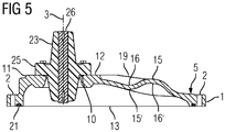
- FIG. 5 shows a cross section through the wall 4 together with flange 1 and the second phase conductor feedthrough 23 with a phase conductor 26, wherein the position of the cutting plane of the FIG. 5 in the FIG. 3 is shown.
- the shape complementary arrangement of a survey 15 on the facing side of the wall 4 and a counter-shaped depression 16 'on the opposite side of the wall 4 recognizable.
- arranged on the facing side sink 16 and its complementary shape survey 15 'on the opposite side is visible.
- the wall 4 has an approximately equal wall thickness in the region of the elevation 15, 15 'and the sink 16, 16'.
- the transverse direction 3 is substantially perpendicular to the position of the first plane 13 and the position of the second plane 12.
- the wall 4 extends from a straight body edge 5 like a desk, wherein in the desk-like rise of the wall 4, the elevations 15, 15 'and the Lowering 16, 16 'in facing away from each other Side of the wall 4 are arranged. In the area of the covenant 11, the vertex of the desk-like rise of the wall 4 is present.
- the collar 11 At the apex of the desk (the wall 4) of the collar 11 is arranged, wherein the collar 11 on the side facing away from the desk-like rise of the wall 4 side adjoins a, substantially vertically upstanding portion of the wall 4, which merges into the flange 1.
- the flange 1, the wall 4 and the collar 11 with the sleepers 17, 18, 19, 20 were integrally formed in the casting process, so that a fluid-tight bond between the individual modules is given.
- a closure of the recesses 6, 7, 8 with the phase conductor bushings 22, 23, 24 is a fluid-tight barrier through the wall 4 together with phase conductor bushings 22, 23, 24 in the inner region of the flange 1, whereby the flange 1 is flanged with a flange and thus a flange opening of the flange is closable.
- a closure can be made fluid-tight due to the use of the corresponding sealing elements.
- phase conductor bushings 22, 23, 24 it is now possible, despite the use of electrically conductive materials for forming the wall 4 and the flange 1, a phase conductor 26 pass electrically insulated through the wall 4, so that on the opposite sides of the wall 4 a electrical contacting of the phase conductor 26 is possible, whereby an electric current is electrically isolated through the wall 4 through transferable.
- the closure element can be used to transmit a multi-phase electric power transmission system through the wall 4 therethrough.
- a multi-phase electric power transmission system may be, for example, a three-phase AC system.
- the closure element is suitable, used on a pressure fluid-insulated encapsulation of an electric power transmission device to become.
- An encapsulating housing surrounds one or more phase conductors for transmitting electrical energy, wherein the interior of the encapsulating housing is filled with an electrically insulating fluid, preferably under overpressure.
- Suitable electrically insulating fluids are gases and liquids. In particular, substances such as sulfur hexafluoride, nitrogen, carbon dioxide, insulating oil, insulating esters, etc. have been found to be suitable.
- the opposite side of the wall 4 of this electrically insulating medium which is preferably under pressure, exposed and adjoins this. The facing side of the wall 4, however, is exposed to the environment of the encapsulating. Accordingly, the wall 4 is part of a fluid-tight barrier and upon pressurization of the electrically insulating fluid part of a pressure vessel.
Landscapes
- Engineering & Computer Science (AREA)
- Power Engineering (AREA)
- Casings For Electric Apparatus (AREA)
- Installation Of Indoor Wiring (AREA)
- Pressure Vessels And Lids Thereof (AREA)
Description
- Die Erfindung betrifft eine Verschlussbaugruppe mit einer Wandung, die zumindest eine Ausnehmung aufweist, welche in einer Querungsrichtung die Wandung durchsetzt und von einem Bund umgriffen ist.
- Eine Verschlussbaugruppe ist beispielsweise aus der Offenlegungsschrift
DE 10 2012 215 246 A1 bekannt. Dort ist ein druckfluidisoliertes Schaltfeld beschrieben, welches Flanschöffnungen aufweist. Die Flanschöffnungen sind jeweils mit einer Verschlussbaugruppe verschlossen, wobei eine Wandung der jeweiligen Verschlussbaugruppe jeweils eine der Flanschöffnungen überspannt. Die dortigen Wandungen sind jeweils mit einer Ausnehmung versehen, welche in einer Querrichtung die Wandung durchsetzt. Bei dem bekannten druckfluidisolierten Schaltfeld sind in die Ausnehmungen jeweils Phasenleiterdurchführungen eingesetzt, so dass eine Verschlussbaugruppe einen Innenraum des druckfluidisolierten Schaltfeldes hermetisch abschließt. Je nach Druckbeaufschlagung des druckfluidisolierten Schaltfeldes sind die Wandungen der Verschlussbaugruppen entsprechend massiv auszugestalten. Mit zunehmenden Drücken sind die Wandungen der Verschlussbaugruppen entsprechend zu verstärken. - Aus der Publikation
FR 2 803 117 EP 2 254 135 A1 bekannt. Aus der internationalen VeröffentlichungWO2014/198580 A1 geht ein Hohlkörper für eine gasisolierte Schaltanlage hervor, welcher in gewölbten Wandungen angesetzte Flansche aufweist. Aus der PatentanmeldungGB 2 191 259 A DE 33 13 192 ist ein Verschlussteil entnehmbar, welches zentrisch eine Erhebung aufweist. - Die bekannten Verschlussbaugruppe weisen vergleichbar hohe Gestehungskosten auf, um auch bei hohen Drücken eine ausreichende Winkelsteifigkeit zu erzielen. Weiterhin weist eine derartige Verschlussbaugruppe auch eine verhältnismäßig große Masse auf. Eine große Masse erschwert einen Transport und eine Handhabe der Verschlussbaugruppe.
- Somit ergibt sich als Aufgabe der Erfindung, eine Verschlussbaugruppe anzugeben, welche bei reduzierter Masse eine hohe Winkelsteifigkeit aufweist.
- Erfindungsgemäß wird die Aufgabe bei einer Verschlussbaugruppe der eingangs genannten Art dadurch gelöst, dass in der Wandung im Wesentlichen in der Querungsrichtung eine Erhebung gewölbt aus der Wandung hervortritt, wobei die Erhebung eine Versteifung der Wandung bewirkt und im Wesentlichen quer zur Querungsrichtung eine Schwelle, Bund und Erhebung verbindend, in der Erhebung sowie in dem Bund mündet.
- Eine Verschlussbaugruppe dient einem Verschluss einer Öffnung, beispielsweise an einem Gehäuse. Die Verschlussbaugruppe kann insbesondere einen fluiddichten Verschluss (bei entsprechender Dichtung der Ausnehmung der Wandung) einer Öffnung an einem Kapselungsgehäuse bewirken. Die Wandung erstreckt sich dabei im Wesentlichen quer zur Querungsrichtung der Ausnehmung, so dass die Wandung der Verschlussbaugruppe insbesondere eine Öffnung in einem Kapselungsgehäuse überspannen kann. Die Wandung kann dabei verschiedenartig geformt bzw. profiliert sein, wobei durch eine Anordnung eine Erhebung in der Wandung eine Versteifung derselben bewirkt wird, wodurch eine Massereduzierung der Wandung selbst und damit der Verschlussbaugruppe erzielt werden kann. Die Erhebung wölbt sich dabei im Wesentlichen in Querungsrichtung der Ausnehmung aus der Wandung bzw. aus einer Oberfläche der Wandung aus. Die Wandstärke der Erhebung kann dabei im Wesentlichen der Wandstärke der Wandung entsprechen. Eine Erhebung kann insbesondere streifenförmig nach Art einer Schulter, insbesondere linear in der Wandung erfolgen, wodurch der Streifen im Wesentlichen quer zur Querungsrichtung liegend angeordnet sein sollte.
- Erfindungsgemäß kann weiter vorteilhaft vorgesehen sein, dass in der Wandung sich im Wesentlichen in der Querungsrichtung eine Senke in die Wandung eintaucht.
- Mittels einer Senke besteht die Möglichkeit, punktuell eine Krümmung in die Wandung einzubringen, wodurch einem Verformen entgegengewirkt wird, da die Wandung eine Versteifung durch die Senke erfährt. Die Senke kann dabei im Wesentlichen hohlkehlenartig ausgeformt sein, wobei sich die Senke in Richtung der Querungsrichtung auswölbt. Eine Senke kann im Wesentlichen streifenförmig, insbesondere linear verlaufen.
- Mit einer Profilierung der Wandung durch eine Erhebung oder eine Senke in der Wandung kann deren Steifheit verstärkt werden.
- Insbesondere bei mehreren Ausnehmungen, welche beabstandet zueinander angeordnet sind, kann ein streifenförmiger bzw. bandartiger Verlauf der Erhebung bzw. der Senke vor den Ausnehmungen, d. h. insbesondere im Wesentlichen parallel zu einer Achse, welche die beiden Ausnehmungen in einer Draufsicht in Querungsrichtung verbindet, erfolgen. Weiterhin sollte bei einem bandartigen bzw. streifenförmigen Ausgestalten der Erhebung bzw. der Senke ein hohlkehlenartiges Profil (Senke) bzw. ein schulterartiges Profil (Erhebung) vorgesehen sein, welche entlang einer Bahn, insbesondere einer Geraden, im Wesentlichen bandartig verläuft.
- Dabei kann vorgesehen sein, dass durch die Erhebung eine Verstärkung der Wandungsstärke im Bereich der Erhebung erfolgt. Es kann vorgesehen sein, dass durch die Senke eine Reduzierung der Wandungsstärke im Bereich der Senke erfolgt. Es kann jedoch auch vorgesehen sein, dass sowohl im Bereich der Wandung und/oder im Bereich der Senke eine annähernd gleichbleibende Wandungsstärke im Vergleich zur Wandstärke der Wandung am Übergang zu der Erhebung bzw. zu der Senke vorgesehen ist.
- Eine vorteilhafte Ausgestaltung kann vorsehen, dass Erhebung und Senke versetzt zueinander angeordnet sind.
- Durch einen Versatz einer Erhebung und einer Senke ist es möglich, Erhebung und Senke ineinander übergehen zu lassen, so dass ausgehend von einem Bodenbereich der Senke zu einer Spitze der Erhebung eine vergrößerte Auslenkung in der Querungsrichtung in der Wandung erzielt wird. Damit kann eine zusätzliche Versteifung in der Wandung der Verschlussbaugruppe erzielt werden, wodurch vergrößerte Öffnungen mittels der Verschlussbaugruppe verschlossen werden können. Bei einem Versatz von Erhebung und Senke zueinander kann vorgesehen sein, dass der Verlauf von Erhebung und Senke im Wesentlichen in paralleler Art und Weise erfolgt. So kann beispielsweise auch ein s-förmig geschwungener Bereich in der Wandung erzeugt werden, indem ein gegensinniges Wölben der Wandung im Bereich der Erhebung sowie im Bereich der Senke hervorgerufen wird.
- Weiterhin wird durch einen Versatz der Erhebung und der Senke zueinander ein vergrößerter Flächenbereich in der Wandung geschaffen, welcher gegensinnig ansteigende Bereiche in der Wandung zur Verfügung stellt, wodurch eine erhöhte Verwindungssteifigkeit der Verschlussbaugruppe erzielt werden kann.
- Eine vorteilhafte Ausgestaltung kann vorsehen, dass Erhebung und Senke auf voneinander abgewandten Seiten der Wandung liegen.
- Eine Anordnung von einer Erhebung und einer Senke auf voneinander abgewandten Seiten kann bewirken, die Erhebung und die Senke nicht nur in die gleiche Richtung auszubauchen, sondern auch mit gleichem Richtungssinn ausbauchen zu lassen. Dadurch können an der Verschlussbaugruppe Auswölbungen entstehen, welche beispielsweise im Innern eines Kapselungsgehäuses einen vergrößerten Aufnahmeraum zur Verfügung stellen.
- Weiter kann vorteilhaft vorgesehen sein, dass Erhebung und Senke fluchtend angeordnet sind.
- Bei einer fluchtenden Anordnung (insbesondere in Querungsrichtung) von Erhebung und Senke auf insbesondere voneinander abgewandten Seiten ist es vorteilhaft, wenn die Erhebung sowie die Senke in Querungsrichtung gesehen eine annähernd deckungsgleiche Ausdehnung aufweisen. Bei einem derartigen Übereinanderliegen können Erhebung und Senke in der Wandung beispielsweise eine Ausbauchung bzw. Einsickung bewirken, wobei die Wandstärke der Wandung annähernd in der Ausbauchung bzw. Einsickung beibehalten werden kann. Es kann auch vorgesehen sein, dass die Erhebung und die Senke zwar fluchtend angeordnet sind, jedoch die Profilierung von Erhebung und Senke voneinander abweichen, wodurch auch eine zusätzliche Profilierung der Wandungsstärke im Bereich der Senke bzw. der Erhebung bewirkt werden kann.
- Eine weitere vorteilhafte Ausgestaltung kann vorsehen, dass im Wesentlichen quer zur Querungsrichtung eine Schwelle in der Senke mündet.
- Eine Schwelle, welche im Wesentlichen quer zur Querungsrichtung liegt, kann insbesondere im Wesentlichen lotrecht zur Querungsrichtung ausgerichtet sein. Dabei kann die Schwelle in einer Erhebung bzw. in einer Senke münden, so dass Kräfte ausgehend von der Erhebung bzw. der Senke in die Schwelle eingeleitet und fortgeleitet werden können. Im Bereich der Schwelle sollte die Wandungsstärke durch die Schwelle selbst vergrößert werden, so dass die Wandungsstärke in der Senke bzw. in der Erhebung eine Profilierung erfährt, wodurch ein flächiger Verbund (gegebenenfalls einstückig) zwischen Schwelle und Senke bzw. Erhebung gegeben ist. Eine Schwelle kann dabei verschiedenartige Querschnittprofile aufweisen. Als geeignet haben sich beispielsweise im Wesentlichen rechteckige Profile erwiesen, welche im Bereich des Überganges in die Erhebung bzw. in die Senke mit einer Querschnittreduktion versehen sein können.
- Eine weitere vorteilhafte Ausgestaltung kann vorsehen, dass mehrere Schwellen im Wesentlichen parallel zueinander verlaufend angeordnet sind.
- Mehrere parallel zueinander angeordnete Schwellen können beispielsweise linear gestreckt ausgebildet sein. Es kann jedoch auch vorgesehen, dass die Schwellen einen beliebigen Kurvenverlauf folgen, wobei der Kurvenverlauf der einzelnen Schwellen annähernd parallel zueinander liegen sollte. Eine Nutzung mehrerer Schwellen ermöglicht eine Bündelung von Kräften in den einzelnen Schwellen, wodurch andere Bereiche der Wandung von Kräften entlastet werden.
- Es ist erfindungsgemäß vorgesehen, dass die Ausnehmung von einem Bund umgriffen ist.
- Ein Umgriff einer Ausnehmung mittels eines Bundes bewirkt eine Wandungsverstärkung, wodurch ein Ausreißen der Ausnehmungen bei mechanischer Belastung erschwert ist. An dem Bund können beispielsweise auch Befestigungselemente angreifen, wodurch ein die Ausnehmung verschließendes Element auch fixiert werden kann. Beispielsweise können in dem Bund Gewindebohrungen in Sacklöchern angeordnet sein.
- Es ist erfindungsgemäß vorgesehen, dass zumindest eine der Schwellen im dem Bund mündet.
- Eine Mündung einer Schwelle in dem Bund gestattet es, den Bund über die Schwelle mit der Erhebung bzw. der Senke zu verbinden, so dass Kräfte, welche am Bund angreifen, über die Schwelle auch in die Bereich der Erhebung bzw. der Senke eingeleitet werden können. Damit kommt eine Stabilisierung der Wandung der Verschlussbaugruppe zum Tragen, so dass eine massereduzierte Verschlussbaugruppe gebildet werden kann, welche in sich winkelstarr ausgebildet ist.
- Eine weitere vorteilhafte Ausgestaltung kann vorsehen, dass die Senke und/oder die Erhebung streifenförmig verlaufen.
- Ein streifenförmiger Verlauf der Senke bzw. der Erhebung führt zu einer hohlkehlenförmigen Senke bzw. einer schulterartigen Erhebung, wobei sowohl die Senke als auch die Erhebung frei von scharfkantigen Körperkanten sein sollten. So ist es beispielsweise möglich, dass die Senke einen wannenförmigen Querschnitt aufweist, wohingegen die Erhebung in Richtung des Verlaufes des Streifens eine positiv gekrümmte Oberfläche aufweist. Durch die Streifenform kann sich die Erhebung bzw. die Senke auch über verlängerte Bereiche erstrecken. Vorteilhaft können Kräfte auch über eine Schwelle in einen Bund an der Ausnehmung übertragen werden. Eine Schwelle kann im Wesentlichen quer zu der Senke bzw. der Erhebung verlaufen.
- Eine weiter vorteilhafte Ausgestaltung kann vorsehen, dass in die Ausnehmung eine Phasenleiterdurchführung eingesetzt ist.
- Eine Phasenleiterdurchführung ist eine Einrichtung, mittels welcher ein elektrisch leitfähiger Phasenleiter die Wandung der Verschlussbaugruppe passiert. Dabei sollte das Passieren zum einen elektrisch isoliert vorgesehen sein, zum anderen sollte die Phasenleiterdurchführung nebst Phasenleiter die Ausnehmung fluiddicht verschließen. So ist die Möglichkeit gegeben, mittels der Verschlussbaugruppe eine Öffnung an einem Kapselungsgehäuse fluiddicht zu verschließen, wobei ein Phasenleiter der Phasenleiterdurchführung in Querungsrichtung der Ausnehmung die Wandung durchsetzt. Insbesondere kann die Wandung aus einem elektrisch leitfähigen Material, beispielsweise einem Metall wie Aluminium, ausgebildet sein. Als vorteilhaft haben sich metallische Gusskörper erwiesen, um eine Wandung auszuformen. Ein Gusskörper an sich kann fluiddicht ausgeführt sein.
- Eine weitere vorteilhafte Ausgestaltung kann vorsehen, dass die Wandung zumindest eine im Wesentlichen gerade Körperkante aufweist, zu welcher eine Achse zwischen einer ersten Ausnehmung und einer zweiten Ausnehmung im Wesentlichen parallel ausgerichtet ist.
- Eine Wandung kann beispielsweise eine im Wesentlichen rechteckförmige Grundstruktur aufweisen, wobei im Wesentlichen lotrecht zur Draufsicht auf die Rechteckform der Wandung die Querungsrichtung der Ausnehmungen angeordnet ist. Sind nunmehr mehrere Ausnehmungen in der Wandung angeordnet, so sind diese bevorzugt beabstandet voneinander angeordnet, wobei die Ausnehmungen auf einer Achse versetzt angeordnet sein können. Der Verlauf der Achse sollte parallel zu einer insbesondere geraden Körperkante der Wandung ausgerichtet sein. Insbesondere bei dem Vorhandensein von drei auf einer Achse liegenden Ausnehmungen sollte diese Achse quer zur Querungsrichtung und parallel zu einer geraden Körperkante der Wandung ausgerichtet sein. Parallel zu dieser Achse kann auch der Verlauf einer streifenartigen Erhebung bzw. einer streifenartigen Senke vorgesehen sein, so dass beispielsweise ein s-förmig gewelltes Profil in der Wandung erzielt werden kann.
- Eine weiter vorteilhafte Ausgestaltung kann vorsehen, dass die Wandung Teil eines Flanschdeckels ist.
- Ein Flanschdeckel ist eine Verschlussbaugruppe, welche einem Verschließen einer Flanschöffnung eines Flansches dient. Dabei kann der Flanschdeckel bevorzugt fluiddicht mit dem Flansch verflanscht werden, wobei die Wandung eine Flanschöffnung des Flansches überspannt und verschließt. Dabei ist vorteilhaft vorsehbar, dass der Flanschdeckel die Flanschöffnung fluiddicht verschließt, wobei in die Ausnehmung der Wandung eine Phasenleiterdurchführung fluiddicht eingesetzt sein kann, so dass ein Hindurchtreten von einem Fluid durch die Verschlussbaugruppe selbst bzw. durch einen Fügespalt zwischen Verschlussbaugruppe und Flansch verhindert ist.
- Eine weitere vorteilhafte Ausgestaltung kann vorsehen, dass die Wandung von einem Flanschblatt zumindest teilweise umgriffen ist, in welchem die Wandung pultartig verkippt angeordnet ist.
- Durch einen pultartigen Verlauf der Wandung wird eine Wandung geschaffen, welche insbesondere relativ zu der Ebene des Flanschblattes bzw. relativ zur Ebene der Anpressfläche des Bundes geneigt verläuft. Insbesondere kann durch eine asymmetrische pultartige Verkippung ein asymmetrischer Anstieg innerhalb der Wandung erzielt werden, so dass zusätzlich zu einer Erhebung oder einer Senke eine Kante in der Wandung auf Grund eines keilartigen Pultanstieges gegeben ist. Insbesondere kann ein asymmetrischer Verlauf der Verkippung vorgesehen sein, so dass beispielsweise ein Anstieg von einer geraden Körperkante hin zu dem Bund der Verschlussbaugruppe gegeben ist, wobei vom Bund wiederum ein Abfallen hin zu der Ebene des Flanschblattes erfolgen kann. Dabei ist der keilförmige Anstieg über eine größere Wegstrecke ausgedehnt als eine Wegstrecke eines Abfalles von dem Bund zu der Ebene des Flanschblattes zurück.
- Insbesondere ein keilartiger Anstieg einer pultartig verkippten Wandung kann mit einer Erhebung bzw. mit einer Senke versehen sein, so dass derartige Flächen, die insbesondere freitragend über einer Flanschöffnung positioniert sein können, in sich stabilisiert sind. Somit ist es möglich, lediglich im Bereich des Bundes eine Materialverstärkende Wandungsdicke vorzusehen und den pultartigen Anstieg durch eine Profilierung mit Senke bzw. Erhebung gegebenenfalls zusätzlich mit Schwellen verstärkt auszugestalten. Damit kann einerseits eine winkelsteife Struktur geschaffen werden, die in Ausnehmungen Phasenleiterdurchführungen aufnehmen kann und diese positioniert. Andererseits kann der Bereich, welcher einem Überspannen und Abdecken einer Flanschöffnung dient und nicht einem unmittelbaren Haltern von Phasendurchführungen zur Verfügung stehen muss, mit einer reduzierten Wandungsstärke versehen sein.
- Eine weitere vorteilhafte Ausgestaltung kann vorsehen, dass das Flanschblatt eine Anlagefläche in einer ersten Ebene aufweist und der Bund eine Anlagefläche in einer zweiten Ebene aufweist, wobei die beiden Ebenen im Wesentlichen parallel zueinander ausgerichtet sind.
- Durch eine Definition einer ersten Ebene sowie einer zweiten Ebene, die im Wesentlichen parallel liegen, ist ein Raum geschaffen, innerhalb welchem eine Wandung nebst Einsenkung bzw. Erhebung einen Formverlauf aufweisen kann. Durch eine Parallelanordnung der ersten sowie der zweiten Ebene sind das Flanschblatt sowie die Anlagefläche des Bundes parallel zueinander ausgerichtet. Der lotrechte Abstand zwischen den beiden Ebenen kann dabei die maximale Höhe der Wandung begrenzen. Somit ist es möglich, trotz Abweichungen von lotrechten bzw. rechtwinkligen Strukturen der Wandung genormte Anlagebereiche an der Verschlussbaugruppe anzuordnen und dabei innerhalb dieses Bereiches eine profilierte Wandung unterzubringen. Insbesondere bei einem pultartigen Verkippen der Wandung können so asymmetrische Verläufe innerhalb der Wandung erzeugt werden, wobei jedoch stets normierte Anlageflächen in einer ersten sowie einer zweiten Ebene vorgesehen sind, die wiederum im Wesentlichen parallel zueinander ausgerichtet sind und die Ausdehnung der Wandung in Querungsrichtung begrenzen. Bevorzugt können die Anlageflächen der ersten Ebene sowie der zweiten Ebene entgegengesetzt zueinander ausgerichtet sein, so dass Anpresskräfte mit entgegengesetztem Richtungssinn in die Verschlussbaugruppe eingeleitet werden können. Vorteilhaft kann dabei vorgesehen sein, dass die Anlagefläche des Bundes sich zumindest teilweise in Schwellen hinein erstreckt, wodurch ein kammartiger Abschluss der Anlagefläche des Bundes erzeugbar ist.
- Im Folgenden wird ein Ausführungsbeispiel der Erfindung schematisch in einer Figur gezeigt und nachfolgend näher beschrieben. Dabei zeigt die
- Fig. 1
- eine perspektivische Draufsicht auf eine Verschlussbaugruppe, die
- Fig. 2
- eine perspektivische Unteransicht der aus der
Fig. 1 bekannten Verschlussbaugruppe, die - Fig. 3
- eine perspektivische Draufsicht der Verschlussbaugruppe wie in der
Fig. 1 gezeigt, komplettiert mit Phasenleiterdurchführungen, - Fig. 4
- eine perspektivische Unteransicht der Verschlussbaugruppe wie aus der
Fig. 2 bekannt komplettiert mit Phasenleiterdurchführungen und die - Fig. 5
- einen Querschnitt durch die Verschlussbaugruppe.
- Die
Figur 1 zeigt eine Verschlussbaugruppe in einer perspektivischen Draufsicht. Die Verschlussbaugruppe weist ein Flanschblatt 1 auf. Das Flanschblatt 1 weist im Wesentlichen einen rechteckigen Verlauf auf, wobei die Ecken gerundet gebrochen sind. Das Flanschblatt 1 ist von mehreren Bohrungen 2 durchsetzt, wobei die Bohrungen 2 das Flanschblatt 1 in einer Querungsrichtung 3 durchsetzen. Die Bohrungen 2 sind untereinander sowie zur Querungsrichtung 3 im Wesentlichen parallel ausgerichtet. Das Flanschblatt 2 dient einem Befestigen der Verschlussbaugruppe an einem gegengleich ausgebildeten Flansch, um eine Flanschöffnung des Flansches mittels der Verschlussbaugruppe zu verschließen. In dem von dem Flanschblatt 1 umgriffenen Bereich erstreckt sich eine Wandung 4 der Verschlussbaugruppe. Vorliegend ist das Flanschblatt 1 in sich vollständig geschlossen umlaufend ausgebildet, so dass innenmantelseitig am Flanschblatt 1 ein vollständiger Umschluss der bzw. Anschluss an die Wandung 4 gegeben ist. Alternativ kann auch vorgesehen sein, dass das Flanschblatt 1 lediglich abschnittsweise ausgebildet ist, wobei in Umlaufrichtung verteilt beispielsweise mehrere Laschen entlang des in derFigur 1 gezeigten Weges des Flanschblattes 1 angeordnet sind, um ein entsprechendes Befestigen der Verschlussbaugruppe zu ermöglichen. - Die Wandung 4 weist vorliegend einen pultartigen Verlauf auf, wobei von einer geraden Körperkante 5, welche an einem entsprechend geraden Abschnitt des Flanschblattes 1 anliegt, ein keilartiger Anstieg der Wandung 4 erfolgt. Dabei ist der keilartige Anstieg derart ausgebildet, dass eine Profilierung des Anstiegskeiles vorgenommen wurde. An der auf der gegenüber liegenden Seite zur geraden Körperkante 5 liegenden Seite der Wandung 4 weist die Wandung 4 einen im Wesentlichen in Querungsrichtung 3 abfallenden Verlauf auf, um die keilartige Erhebung der Wandung 5 auszugleichen und die Wandung 4 mit dem Flanschblatt 1 zu verbinden.
- In der Wandung 4 sind eine erste Ausnehmung 6, eine zweite Ausnehmung 7 sowie eine dritte Ausnehmung 8 angeordnet. Die Ausnehmungen 6, 7, 8 durchsetzen die Wandung 4 in Querungsrichtung 3. Dabei sind die Ausnehmungen 6, 7, 8 gleichartig dimensioniert. Die Ausnehmungen 6, 7, 8 weisen jeweils einen kreisrunden Querschnitt auf, wobei die Ausnehmungen 6, 7, 8 entlang einer Achse 9 beabstandet zueinander angeordnet sind. Die Achse 9 liegt dabei im Wesentlichen parallel zur geraden Körperkante 5. Die Ausnehmungen 6, 7, 8 sind jeweils von einer Ringnut 10 umschlossen. Die Ringnuten 10 ihrerseits sind in die Wandung 4 eingebracht. Dazu weist die Wandung 4 einen Bund 11 auf, welcher die Ausnehmungen 6, 7, 8 umgreift. Der Bund 11 weist eine entsprechende Anlagefläche auf, welche in einer zweiten Ebene 12 liegt. In der zweiten Ebene 12 der Anlagefläche münden die Ringnuten 10. Weiter sind am Umfang der Ausnehmungen 6, 7, 8 Sacklöcher 14 mit Innengewinde angeordnet, mittels welcher weitere Bauteile gegen die Anlagefläche verspannt werden können.
- Weiter ist im Bereich des keilförmigen Anstieges der Wandung 4 eine Erhebung 15 angeordnet. Die Erhebung 15 erstreckt sich im Wesentlichen streifenartig, parallel zur geraden Körperkante 5 sowie parallel zur Achse 9. Im Bereich zwischen der Erhebung 15 sowie dem Bund 11 ist im Anstieg der Wandung 4 eine Senke 16 angeordnet. Dadurch ist im Bereich der ansteigenden Wandung 4 eine wellenartige Struktur mit positiver sowie negativer Krümmung gegeben. Die Senke 16 erstreckt sich ebenfalls im Wesentlichen streifenförmig, wobei der Verlauf der Erhebung 15 sowie der Senke 16 parallel zueinander erfolgt.
- Weiter sind eine erste Schwelle 17, eine zweite Schwelle 18, eine dritte Schwelle 19 sowie eine vierte Schwelle 20 auf die Wandung 4 aufgesetzt. Die Schwellen 17, 18, 19, 20 verstärken dabei die Wandung 4. Dabei ist der Verlauf der Schwellen 17, 18, 19, 20 ebenfalls im Wesentlichen streifenförmig gewählt, wobei die Streifen sich linear erstrecken und im Wesentlichen quer zur Querungsrichtung 3 verlaufen. Die Schwellen 17, 18, 19, 20 sind parallel zueinander ausgerichtet und beabstandet zueinander angeordnet. Dabei ist der Verlauf der Achsen der streifenförmigen Erhebung 15 bzw. der streifenförmigen Senke 16 im Wesentlichen quer zur Ausrichtung der Schwellen 17, 18, 19, 20 gewählt. Dadurch verbindet jede der Schwellen 17, 18, 19, 20 die Erhebung 15 sowie die Senke 16 mit dem Bund 11. Dabei ist die Gestalt der Schwellen 17, 18, 19, 20 derart gewählt, dass Abschnitte der Schwelle Teile der Anlagefläche des Bundes 11 ausbilden, so dass eine kammartige Begrenzung der Anlagefläche des Bundes 11 im Mündungsbereich der Schwellen 17, 18, 19, 20 an dem Bund 11 gegeben ist.
- Vorliegend ist die Ausgestaltung von der Erhebung 15 sowie der Senke 16 derart gewählt, dass auf ihren jeweils abgewandten Seiten eine gegensinnige Ausformung vorgenommen wurde, so dass die Erhebung 15 auf der abgewandten Seite (der in der
Figur 2 gezeigten Seite) in der Wandung 4 eine Senke 16' zur Verfügung stellt. Somit sind die Senke 16' auf der abgewandten Seite der Wandung 4 sowie die formkomplementäre Erhebung 15 auf der zugewandten Seite der Wandung 4 fluchtend deckungsgleich angeordnet. Analoges gilt für die auf der zugewandten Seite liegende Senke 16 sowie auf der abgewandten Seite formkomplementär ausgeformte Erhebung 15'. Durch eine derartige formkomplementäre Ausbildung ist die Wandungsstärke im Wesentlichen gleichbleibend ausgebildet, wobei durch die Anordnung der Schwellen 17, 18, 19, 20 eine Verstärkung der Wandung 4 im Bereich der Schwellen 17, 18, 19, 20 gegeben ist. Vorzugsweise sollten die Schwellen 17, 18, 19, 20 einstückig mit der Wandung 4 ausgeformt sein. Es kann jedoch auch vorgesehen sein, dass die Schwellen 17, 18, 19, 20 als diskrete Bauteile ausgebildet sind, welche einen winkelstarren Verbund mit der Wandung 4 aufweisen. - Vorliegend ist die Verschlussbaugruppe als Flanschdeckel ausgeführt, so dass mittels des Flanschblattes 1, welches in einer ersten Ebene 13 liegt, ein formkomplementärer Flansch verschließbar ist. Die Wandung 4 überspannt dabei eine Flanschöffnung des Flansches und dichtet diese ab. Dabei kann vorgesehen sein, dass die Wandung 4 nebst Übergang zu dem Flanschblatt 1 fluiddicht ausgebildet ist, wobei zur fluiddichten Ausgestaltung der Verschlussbaugruppe auch die Ausnehmungen 6, 7, 8 entsprechend fluiddicht zu verschließen sind (vgl. dazu
Figuren 3, 4 und5 ). - Vorteilhafterweise kann die Wandung 4 nach Art eines metallischen Gusskörpers ausgebildet sein, wobei das Flanschblatt 1 einstückig mit der Wandung 4 ausgebildet ist. Entsprechend können effizient in einem Gussverfahren die entsprechenden Erhebungen, Senken sowie der Bund usw. ausgeformt werden.
- In der
Figur 2 ist die in derFigur 1 gezeigte Verschlussbaugruppe mit ihrer abgewandten Seite gezeigt. Entsprechend erkennbar ist, dass die Erhebung 15 gemäßFigur 1 auf ihrer abgewandten Seite eine entsprechende Senke 16' ausbildet, wobei die in der zugwandten Seite derFigur 1 gezeigte Senke 16 auf der abgewandten Seite nachFigur 2 eine entsprechende Erhebung 15' ausbildet. Weiterhin ist zu erkennen, dass im Bereich der Ausnehmungen 6, 7, 8 eine Verstärkung der Wandung 4 vorgesehen ist, um insbesondere die Aufnahme der Sacklöcher 14 mit Innengewinde zu realisieren, wobei die Wandung 4 von den Sacklöchern 14 mit Innengewinde nicht vollständig durchsetzt ist. Entsprechend ist eine bis auf die Ausnehmungen 6, 7, 8 durchgriffsfreie Wandung 4 gegeben. Um die Verschlussbaugruppe fluiddicht mit einem Flansch zu verbinden, ist im Flanschblatt 1 auf der abgewandten Seite gemäßFigur 2 eine Ringnut 21 eingebracht, in welche ein Dichtungselement, beispielsweise ein elastisch verformbarer O-Ring, einlegbar ist. - In den
Figuren 3 und 4 ist ein fluiddichter Verschluss der Ausnehmung 6, 7, 8 mittels einer ersten Phasenleiterdurchführung 22, einer zweiten Phasenleiterdurchführung 23 sowie einer dritten Phasenleiterdurchführung 24 gezeigt. Die Phasenleiterdurchführungen 22, 23, 24 weisen einen gleichartigen Aufbau auf. Jede der Phasenleiterdurchführungen 22, 23, 24 weist eine Ringscheibe 25 auf, wobei die Ringscheibe 25 von Durchgangsbohrungen durchsetzt ist, in welche Bolzen eingesetzt sind, die wiederum in den Sacklöchern 14 mit Innengewinde im Bund 11 verspannt sind. Dadurch können die Ringscheiben 25 gegen in den Ringnuten 10 eingelegte, elastisch verformbare Dichtungsringe gepresst werden, so dass einerseits eine fluiddichte Verbindung zwischen den Phasenleiterdurchführungen 22, 23, 24 sowie der Wandung 4 und andererseits eine mechanische Positionierung der jeweiligen Phasenleiterdurchführungen 22, 23, 24 gegeben ist. Die Ringscheiben 25 der Phasenleiterdurchführung 22, 23, 24 sind in Querungsrichtung 3 von jeweils einem Phasenleiter 26 durchsetzt. Die Phasenleiter 26 sind fluiddicht in ein Isolierstoffmaterial eingebettet, welches zur Ausbildung der Ringscheiben 25 dient. Das Isolierstoffmaterial ist beiderseits stirnseitig ausgehend von den Ringscheiben 25 jeweils in Querungsrichtung 3 verlaufend als Konus ausgeformt. Auf der zugewandten Seite nachFigur 3 sowie auf der abgewandten Seite nachFigur 4 sind die Konusse jeweils einer Phasenleiterdurchführung 22, 23, 24 koaxial jedoch gegensinnig ausgerichtet. Somit ist ein fluiddichter Isolierstoffkörper gebildet, welcher ausgehend von den Ringscheiben 25 in Querungsrichtung 3 gegensinnige Konusse aufweist, wobei die Phasenleiter 26 in den Isolierstoffkörpern in Querungsrichtung 3 verlaufend zentrisch eingebettet sind. Die Phasenleiter 26 weisen beispielsweise eine Gestalt als massive metallische Zylinder mit kreisförmigem Querschnitt auf, wobei stirnseitig Gewindebohrungen eingebracht sind, um eine elektrische sowie mechanische Kontaktierung der Phasenleiter 26 der Phasenleiterdurchführungen 22, 23, 24 zu ermöglichen. Die Querungsrichtung 3 ist dabei im Wesentlichen lotrecht zur ersten Ebene 13 des Flanschblattes 1 ausgerichtet. - In der
Figur 4 ist die aus derFigur 2 bekannte Darstellung der Verschlussbaugruppe gezeigt, wobei auf der abgewandten Seite die die Ausnehmungen 6, 7, 8 durchsetzenden Phasenleiter 26 mit den sie umgebenden konischen Anformungen des Isolierstoffkörpers erkennbar sind. In die Ringnut 21 des ersten Flanschblattes 1 ist in derFigur 4 auch ein Dichtelement eingelegt. - Die
Figur 5 zeigt einen Querschnitt durch die Wandung 4 nebst Flanschblatt 1 sowie die zweite Phasenleiterdurchführung 23 mit einem Phasenleiter 26, wobei die Lage der Schnittebene derFigur 5 in derFigur 3 gezeigt ist. In der Schnittdarstellung derFigur 5 ist die formkomplementäre Anordnung einer Erhebung 15 auf der zugewandten Seite der Wandung 4 sowie einer gegengleich ausgeformten Senke 16' auf der abgewandten Seite der Wandung 4 erkenntlich. In analoger Weise ist die auf der zugewandten Seite angeordnete Senke 16 und deren formkomplementärer Erhebung 15' auf der abgewandten Seite sichtbar. Die Wandung 4 weist dabei eine annähernd gleichartige Wandungsstärke im Bereich der Erhebung 15, 15' sowie der Senke 16, 16' auf. Lediglich die zur Ankoppelung von weiteren Bauteilen bzw. zur Aufnahme von mechanischen Verspannkräften notwendigen Bereiche, wie das Flanschblatt 1 sowie der Bund 11 sowie Stabilisierungselemente wie die Schwellen 17, 18, 19, 20 wirken wandungsverstärkend. Die Querungsrichtung 3 liegt dabei im Wesentlichen lotrecht zur Lage der ersten Ebene 13 sowie zur Lage der zweiten Ebene 12. Die Wandung 4 verläuft von einer geraden Körperkante 5 pultartig ansteigend, wobei in dem pultartigen Anstieg der Wandung 4 die Erhebungen 15, 15' sowie die Senken 16, 16' in voneinander abgewandten Seiten der Wandung 4 angeordnet sind. Im Bereich des Bundes 11 liegt der Scheitelpunkt des pultartigen Anstieges der Wandung 4 vor. Im Scheitelpunkt des Pultes (der Wandung 4) ist der Bund 11 angeordnet, wobei der Bund 11 auf der vom pultartigen Anstieg der Wandung 4 abgewandten Seite sich an einen, im Wesentlichen lotrecht aufragenden Abschnitt der Wandung 4 anschließt, welcher in das Flanschblatt 1 übergeht. In der Darstellung des Schnittes nachFigur 5 ist weiter erkennbar, dass das Flanschblatt 1 die Wandung 4 sowie der Bund 11 mit den Schwellen 17, 18, 19, 20 einstückig im Gussverfahren ausgeformt wurden, so dass ein fluiddichter Verbund zwischen den einzelnen Baugruppen gegeben ist. Durch einen Verschluss der Ausnehmungen 6, 7, 8 mit den Phasenleiterdurchführungen 22, 23, 24 ist eine fluiddichte Barriere durch die Wandung 4 nebst Phasenleiterdurchführungen 22, 23, 24 im inneren Bereich des Flanschblattes 1 gegeben, wodurch das Flanschblatt 1 mit einem Flansch verflanschbar ist und somit eine Flanschöffnung des Flansches verschließbar ist. Insbesondere kann ein derartiger Verschluss aufgrund der Verwendung der entsprechenden Dichtelemente fluiddicht erfolgen. Mittels der Phasenleiterdurchführungen 22, 23, 24 ist es nunmehr möglich, trotz Verwendung von elektrisch leitfähigen Materialien zur Ausbildung der Wandung 4 sowie des Flanschblattes 1 einen Phasenleiter 26 elektrisch isoliert durch die Wandung 4 hindurchzuführen, so dass auf den voneinander abgewandten Seiten der Wandung 4 eine elektrische Kontaktierung des Phasenleiters 26 möglich ist, wodurch ein elektrischer Strom elektrisch isoliert durch die Wandung 4 hindurch übertragbar ist. Durch die Nutzung mehrerer Phasenleiterdurchführungen 22, 23, 24 mit jeweils einem elektrisch isolierten Phasenleiter 26 kann das Verschlusselement eingesetzt werden, um ein mehrphasiges Elektroenergieübertragungssystem durch die Wandung 4 hindurch zu übertragen. Ein derartiges mehrphasiges Elektroenergieübertragungssystem kann beispielsweise ein dreiphasiges Wechselspannungssystem sein. Entsprechend ist das Verschlusselement geeignet, an einer druckfluidisolierten Kapselung einer Elektroenergieübertragungseinrichtung verwendet zu werden. Ein Kapselungsgehäuse umgibt dabei einen oder mehrere Phasenleiter zur Übertragung von elektrischer Energie, wobei das Innere des Kapselungsgehäuses mit einem elektrisch isolierenden Fluid, bevorzugt unter Überdruck, befüllt ist. Als elektrisch isolierende Fluide eignen sich Gase sowie Flüssigkeiten. Insbesondere haben sich Stoffe wie Schwefelhexafluorid, Stickstoff, Kohlendioxid, Isolieröl, Isolierester usw. als geeignet erwiesen. Dadurch ist die abgewandte Seite der Wandung 4 diesem elektrisch isolierenden Medium, welches bevorzugt unter Überdruck steht, ausgesetzt und grenzt dieses ein. Die zugewandte Seite der Wandung 4 hingegen ist der Umgebung des Kapselungsgehäuses ausgesetzt. Entsprechend ist die Wandung 4 Teil einer fluiddichten Barriere und bei einer Druckbeaufschlagung des elektrisch isolierenden Fluides Teil eines Druckbehälters. -
- 1
- Flanschblatt
- 2
- Bohrung
- 3
- Querungsrichtung
- 4
- Wandung
- 5
- gerade Körperkante
- 6
- erste Ausnehmung
- 7
- zweite Ausnehmung
- 8
- dritte Ausnehmung
- 9
- Achse
- 10
- Ringnut
- 11
- Bund
- 12
- zweite Ebene
- 13
- dritte Ebene
- 14
- Sacklöcher mit Innengewinde
- 15, 15'
- Erhebung
- 16, 16'
- Senke
- 17
- erste Schwelle
- 18
- zweite Schwelle
- 19
- dritte Schwelle
- 20
- vierte Schwelle
- 21
- Ringnut
- 22
- erste Phasenleiterdurchführung
- 23
- zweite Phasenleiterdurchführung
- 24
- dritte Phasenleiterdurchführung
- 25
- Ringscheibe
- 26
- Phasenleiter
Claims (13)
- Verschlussbaugruppe für den Verschluss einer Öffnung an einem druckfluidisolierten Kapselungsgehäuse, mit einer Wandung (4), die zumindest eine Ausnehmung (6, 7, 8) aufweist, welche in einer Querungsrichtung (3) die Wandung (4) durchsetzt und von einem Bund (11) umgriffen ist,
dadurch gekennzeichnet, dass
in der Wandung (4) im Wesentlichen in der Querungsrichtung (3) eine Erhebung (15, 15') gewölbt aus der Wandung (4) hervortritt, wobei die Erhebung (15, 15') eine Versteifung der Wandung (4) bewirkt und im Wesentlichen quer zur Querungsrichtung eine Schwelle (17, 18, 19, 20), Bund (11) und Erhebung (15, 15') verbindend, in der Erhebung (15, 15') sowie in dem Bund (11) mündet. - Verschlussbaugruppe nach Anspruch 1,
dadurch gekennzeichnet, dass
in der Wandung (4) sich im Wesentlichen in der Querungsrichtung (3) eine Senke (16, 16') in die Wandung (4) eintaucht. - Verschlussbaugruppe nach Anspruch 1 oder 2,
dadurch gekennzeichnet, dass
Erhebung (15, 15') und Senke (16, 16') versetzt zueinander angeordnet sind. - Verschlussbaugruppe nach einem der Ansprüche 1 bis 3,
dadurch gekennzeichnet, dass
Erhebung (15, 15') und Senke (16, 16') auf voneinander abgewandten Seiten der Wandung (4) liegen. - Verschlussbaugruppe nach Anspruch 4,
dadurch gekennzeichnet, dass
Erhebung (15, 15') und Senke (16, 16') fluchtend angeordnet sind. - Verschlussbaugruppe nach einem der Ansprüche 1 bis 5,
dadurch gekennzeichnet, dass
im Wesentlichen quer zur Querungsrichtung (3) eine Schwelle (17, 18, 19, 20) in der Senke (16, 16') mündet. - Verschlussbaugruppe nach Anspruch 6,
dadurch gekennzeichnet, dass
mehrere Schwellen (17, 18, 19, 20) im Wesentlichen parallel zueinander verlaufend angeordnet sind. - Verschlussbaugruppe nach einem der Ansprüche 1 bis 7,
dadurch gekennzeichnet, dass
die Senke (16, 16') und/oder die Erhebung (15, 15'9 streifenförmig verlaufen. - Verschlussbaugruppe nach einem der Ansprüche 1 bis 8,
dadurch gekennzeichnet, dass
in die Ausnehmung (6, 7, 8) eine Phasenleiterdurchführung (22, 23, 24) eingesetzt ist. - Verschlussbaugruppe nach Anspruch 1 bis 9,
dadurch gekennzeichnet, dass
die Wandung (4) zumindest eine im Wesentlichen gerade Körperkante (5) aufweist, zu welcher eine Achse (9) zwischen einer ersten Ausnehmung (6, 7, 8) und einer zweiten Ausnehmung (6, 7, 8) im Wesentlichen parallel ausgerichtet ist. - Verschlussbaugruppe nach einem der Ansprüche 1 bis 10,
dadurch gekennzeichnet, dass
die Wandung (4) Teil eines Flanschdeckels ist. - Verschlussbaugruppe nach einem der Ansprüche 1 bis 11,
dadurch gekennzeichnet, dass
die Wandung (4) von einem Flanschblatt (1) zumindest teilweise umgriffen ist, in welchem die Wandung (4) pultartig verkippt angeordnet ist. - Verschlussbaugruppe nach Anspruch 12,
dadurch gekennzeichnet, dass
das Flanschblatt (1) eine Anlagefläche in einer ersten Ebene (13) aufweist und der Bund (11) eine Anlagefläche in einer zweiten Ebene (12) aufweist, wobei die beiden Ebenen (12, 13) im Wesentlichen parallel zueinander ausgerichtet sind.
Applications Claiming Priority (2)
| Application Number | Priority Date | Filing Date | Title |
|---|---|---|---|
| DE102015205915.4A DE102015205915A1 (de) | 2015-04-01 | 2015-04-01 | Verschlussbaugruppe mit einer Wandung |
| PCT/EP2016/056813 WO2016156324A1 (de) | 2015-04-01 | 2016-03-29 | Verschlussbaugruppe mit einer wandung |
Publications (2)
| Publication Number | Publication Date |
|---|---|
| EP3254349A1 EP3254349A1 (de) | 2017-12-13 |
| EP3254349B1 true EP3254349B1 (de) | 2019-10-30 |
Family
ID=55697157
Family Applications (1)
| Application Number | Title | Priority Date | Filing Date |
|---|---|---|---|
| EP16714828.7A Active EP3254349B1 (de) | 2015-04-01 | 2016-03-29 | Verschlussbaugruppe mit einer wandung |
Country Status (4)
| Country | Link |
|---|---|
| EP (1) | EP3254349B1 (de) |
| DE (1) | DE102015205915A1 (de) |
| ES (1) | ES2765189T3 (de) |
| WO (1) | WO2016156324A1 (de) |
Families Citing this family (1)
| Publication number | Priority date | Publication date | Assignee | Title |
|---|---|---|---|---|
| EP3671985A1 (de) * | 2018-12-21 | 2020-06-24 | ABB Schweiz AG | Behälter für eine gasisolierte schaltanlage mit mittlerer spannung |
Family Cites Families (15)
| Publication number | Priority date | Publication date | Assignee | Title |
|---|---|---|---|---|
| US1794750A (en) * | 1927-03-30 | 1931-03-03 | Condit Electrical Mfg Corp | Electric-wiring conduit |
| US3515799A (en) * | 1969-02-11 | 1970-06-02 | Westinghouse Electric Corp | Electrical bushing mounted in casing with foamed resin |
| NL160439C (nl) * | 1975-04-07 | 1979-10-15 | Coq Bv | Vermogensschakelaar voor hoge spanning met bolvormig metalen vat. |
| DE3313192A1 (de) * | 1983-04-12 | 1984-10-18 | Brown, Boveri & Cie Ag, 6800 Mannheim | Gekapselte, gasisolierte mittelspannungsschaltanlage |
| CH661610A5 (en) * | 1983-10-19 | 1987-07-31 | Bbc Brown Boveri & Cie | Bushing plate without any control elements |
| KR900008870B1 (ko) * | 1986-05-06 | 1990-12-11 | 미츠비시 덴키 가부시키가이샤 | 밀봉형 전기기기 |
| DE29508111U1 (de) * | 1995-05-17 | 1995-08-10 | DaimlerChrysler AG, 70567 Stuttgart | Leistungskontaktierung für ein Stromrichtergerät |
| DE19615912A1 (de) * | 1996-04-22 | 1997-10-23 | Asea Brown Boveri | Trennschalter |
| FR2803117A1 (fr) * | 1999-12-22 | 2001-06-29 | Schneider Electric Ind Sa | Combine sectionneur d'isolement, sectionneur de terre pour une installation electrique haute tension blindee |
| DE102009022105A1 (de) * | 2009-05-20 | 2010-11-25 | Abb Technology Ag | Gasisolierte Hochspannungsschaltanlage |
| EP2262082A1 (de) * | 2009-06-12 | 2010-12-15 | Siemens Aktiengesellschaft | Elektrodynamische Maschine |
| WO2011037786A1 (en) * | 2009-09-24 | 2011-03-31 | Abb Technology Ag | Bushing assembly for draw-out circuit breaker |
| CN102856065B (zh) * | 2011-06-30 | 2015-11-18 | 特变电工沈阳变压器集团有限公司 | 单相超大容量强电流短路试验变压器 |
| DE102012215246A1 (de) | 2012-08-28 | 2014-03-06 | Siemens Aktiengesellschaft | Druckfluidisoliertes Schaltfeld |
| DE102013211102A1 (de) * | 2013-06-14 | 2014-12-31 | Siemens Aktiengesellschaft | Gestaltungsverfahren eines Hohlkörpers sowie Hohlkörper |
-
2015
- 2015-04-01 DE DE102015205915.4A patent/DE102015205915A1/de not_active Withdrawn
-
2016
- 2016-03-29 EP EP16714828.7A patent/EP3254349B1/de active Active
- 2016-03-29 WO PCT/EP2016/056813 patent/WO2016156324A1/de not_active Ceased
- 2016-03-29 ES ES16714828T patent/ES2765189T3/es active Active
Non-Patent Citations (1)
| Title |
|---|
| None * |
Also Published As
| Publication number | Publication date |
|---|---|
| ES2765189T3 (es) | 2020-06-08 |
| WO2016156324A1 (de) | 2016-10-06 |
| DE102015205915A1 (de) | 2016-10-06 |
| EP3254349A1 (de) | 2017-12-13 |
Similar Documents
| Publication | Publication Date | Title |
|---|---|---|
| EP2984718B1 (de) | Isolationssystem sowie montageverfahren eines isolationssystems | |
| EP1490554A1 (de) | Verankerungsvorrichtung für ein korrosionsgeschütztes zugglied, insbesondere schrägseil für eine schrägseilbrücke | |
| EP2415134B1 (de) | Kapselungsgehäusereduzierstück | |
| DE102011086663A1 (de) | Druckgasisolierte Elektroenergieübertragungseinrichtung | |
| DE102008027642A1 (de) | Anordnung mit einem Kapselungsgehäuse | |
| EP0083092B1 (de) | Kapselung einer elektrischen Mittelspannungsschalt- und -verteileranlage | |
| EP0037796B1 (de) | Gas- oder flüssigkeitsisolierter Stromwandler | |
| DE102015205915A1 (de) | Verschlussbaugruppe mit einer Wandung | |
| EP2259401B1 (de) | Kabelendverschluss für Freiluft- oder Innenraumanwendung | |
| EP3745548B1 (de) | Gasisolierter behälter | |
| DE1475620A1 (de) | Isolierte Rohrverbindungen | |
| WO2019048163A1 (de) | Leitungsanschlussgehäuse | |
| DE4310071C2 (de) | Isolierstoffgehäuseanordnung | |
| DE102008057237A1 (de) | Druckgasisolierte Elektroenergieübertragungsanordnung | |
| EP0678953A1 (de) | Kabelanschluss für eine metallgekapselte gasisolierte Hochspannungsschaltanlage | |
| DE102005031098A1 (de) | Sich im Wesentlichen rohrförmig erstreckendes Kapselungsgehäuse mit zumindest drei Gehäuseabschnitten | |
| DE3347006C2 (de) | ||
| EP2630710B1 (de) | Mehrpolig gasisolierter sammelschienenabschnitt | |
| DE102009024109B3 (de) | Kabelendverschluss für Freiluftanwendung | |
| DE10160736B4 (de) | Hohlwanddose aus Kunststoff | |
| WO2008151857A1 (de) | Überspannungsableiteranordnung | |
| DE102012213339A1 (de) | Losflanschanordnung für eine Elektroenergieübertragungseinrichtung | |
| DE705326C (de) | Verbindungs- und Abzweigdose fuer elektrische Leitungsanlagen | |
| EP3235082B1 (de) | Kabeldurchführung für messleitungen in ein elektrisch isolierende flanschverschlussdeckel | |
| WO2019001862A1 (de) | Isolatoranordnung sowie montageverfahren zur herstellung einer isolatoranordnung |
Legal Events
| Date | Code | Title | Description |
|---|---|---|---|
| STAA | Information on the status of an ep patent application or granted ep patent |
Free format text: STATUS: THE INTERNATIONAL PUBLICATION HAS BEEN MADE |
|
| PUAI | Public reference made under article 153(3) epc to a published international application that has entered the european phase |
Free format text: ORIGINAL CODE: 0009012 |
|
| STAA | Information on the status of an ep patent application or granted ep patent |
Free format text: STATUS: REQUEST FOR EXAMINATION WAS MADE |
|
| 17P | Request for examination filed |
Effective date: 20170906 |
|
| AK | Designated contracting states |
Kind code of ref document: A1 Designated state(s): AL AT BE BG CH CY CZ DE DK EE ES FI FR GB GR HR HU IE IS IT LI LT LU LV MC MK MT NL NO PL PT RO RS SE SI SK SM TR |
|
| AX | Request for extension of the european patent |
Extension state: BA ME |
|
| DAV | Request for validation of the european patent (deleted) | ||
| DAX | Request for extension of the european patent (deleted) | ||
| STAA | Information on the status of an ep patent application or granted ep patent |
Free format text: STATUS: EXAMINATION IS IN PROGRESS |
|
| 17Q | First examination report despatched |
Effective date: 20190313 |
|
| GRAP | Despatch of communication of intention to grant a patent |
Free format text: ORIGINAL CODE: EPIDOSNIGR1 |
|
| STAA | Information on the status of an ep patent application or granted ep patent |
Free format text: STATUS: GRANT OF PATENT IS INTENDED |
|
| INTG | Intention to grant announced |
Effective date: 20190617 |
|
| GRAS | Grant fee paid |
Free format text: ORIGINAL CODE: EPIDOSNIGR3 |
|
| GRAA | (expected) grant |
Free format text: ORIGINAL CODE: 0009210 |
|
| STAA | Information on the status of an ep patent application or granted ep patent |
Free format text: STATUS: THE PATENT HAS BEEN GRANTED |
|
| AK | Designated contracting states |
Kind code of ref document: B1 Designated state(s): AL AT BE BG CH CY CZ DE DK EE ES FI FR GB GR HR HU IE IS IT LI LT LU LV MC MK MT NL NO PL PT RO RS SE SI SK SM TR |
|
| REG | Reference to a national code |
Ref country code: GB Ref legal event code: FG4D Free format text: NOT ENGLISH |
|
| REG | Reference to a national code |
Ref country code: CH Ref legal event code: EP |
|
| REG | Reference to a national code |
Ref country code: CH Ref legal event code: NV Representative=s name: SIEMENS SCHWEIZ AG, CH Ref country code: AT Ref legal event code: REF Ref document number: 1197167 Country of ref document: AT Kind code of ref document: T Effective date: 20191115 |
|
| REG | Reference to a national code |
Ref country code: DE Ref legal event code: R096 Ref document number: 502016007312 Country of ref document: DE |
|
| REG | Reference to a national code |
Ref country code: IE Ref legal event code: FG4D Free format text: LANGUAGE OF EP DOCUMENT: GERMAN |
|
| REG | Reference to a national code |
Ref country code: LT Ref legal event code: MG4D |
|
| PG25 | Lapsed in a contracting state [announced via postgrant information from national office to epo] |
Ref country code: LT Free format text: LAPSE BECAUSE OF FAILURE TO SUBMIT A TRANSLATION OF THE DESCRIPTION OR TO PAY THE FEE WITHIN THE PRESCRIBED TIME-LIMIT Effective date: 20191030 Ref country code: PL Free format text: LAPSE BECAUSE OF FAILURE TO SUBMIT A TRANSLATION OF THE DESCRIPTION OR TO PAY THE FEE WITHIN THE PRESCRIBED TIME-LIMIT Effective date: 20191030 Ref country code: GR Free format text: LAPSE BECAUSE OF FAILURE TO SUBMIT A TRANSLATION OF THE DESCRIPTION OR TO PAY THE FEE WITHIN THE PRESCRIBED TIME-LIMIT Effective date: 20200131 Ref country code: NO Free format text: LAPSE BECAUSE OF FAILURE TO SUBMIT A TRANSLATION OF THE DESCRIPTION OR TO PAY THE FEE WITHIN THE PRESCRIBED TIME-LIMIT Effective date: 20200130 Ref country code: LV Free format text: LAPSE BECAUSE OF FAILURE TO SUBMIT A TRANSLATION OF THE DESCRIPTION OR TO PAY THE FEE WITHIN THE PRESCRIBED TIME-LIMIT Effective date: 20191030 Ref country code: SE Free format text: LAPSE BECAUSE OF FAILURE TO SUBMIT A TRANSLATION OF THE DESCRIPTION OR TO PAY THE FEE WITHIN THE PRESCRIBED TIME-LIMIT Effective date: 20191030 Ref country code: FI Free format text: LAPSE BECAUSE OF FAILURE TO SUBMIT A TRANSLATION OF THE DESCRIPTION OR TO PAY THE FEE WITHIN THE PRESCRIBED TIME-LIMIT Effective date: 20191030 Ref country code: BG Free format text: LAPSE BECAUSE OF FAILURE TO SUBMIT A TRANSLATION OF THE DESCRIPTION OR TO PAY THE FEE WITHIN THE PRESCRIBED TIME-LIMIT Effective date: 20200130 Ref country code: PT Free format text: LAPSE BECAUSE OF FAILURE TO SUBMIT A TRANSLATION OF THE DESCRIPTION OR TO PAY THE FEE WITHIN THE PRESCRIBED TIME-LIMIT Effective date: 20200302 Ref country code: NL Free format text: LAPSE BECAUSE OF FAILURE TO SUBMIT A TRANSLATION OF THE DESCRIPTION OR TO PAY THE FEE WITHIN THE PRESCRIBED TIME-LIMIT Effective date: 20191030 |
|
| REG | Reference to a national code |
Ref country code: NL Ref legal event code: MP Effective date: 20191030 |
|
| PG25 | Lapsed in a contracting state [announced via postgrant information from national office to epo] |
Ref country code: IS Free format text: LAPSE BECAUSE OF FAILURE TO SUBMIT A TRANSLATION OF THE DESCRIPTION OR TO PAY THE FEE WITHIN THE PRESCRIBED TIME-LIMIT Effective date: 20200229 Ref country code: HR Free format text: LAPSE BECAUSE OF FAILURE TO SUBMIT A TRANSLATION OF THE DESCRIPTION OR TO PAY THE FEE WITHIN THE PRESCRIBED TIME-LIMIT Effective date: 20191030 Ref country code: RS Free format text: LAPSE BECAUSE OF FAILURE TO SUBMIT A TRANSLATION OF THE DESCRIPTION OR TO PAY THE FEE WITHIN THE PRESCRIBED TIME-LIMIT Effective date: 20191030 |
|
| REG | Reference to a national code |
Ref country code: ES Ref legal event code: FG2A Ref document number: 2765189 Country of ref document: ES Kind code of ref document: T3 Effective date: 20200608 |
|
| PG25 | Lapsed in a contracting state [announced via postgrant information from national office to epo] |
Ref country code: AL Free format text: LAPSE BECAUSE OF FAILURE TO SUBMIT A TRANSLATION OF THE DESCRIPTION OR TO PAY THE FEE WITHIN THE PRESCRIBED TIME-LIMIT Effective date: 20191030 |
|
| PG25 | Lapsed in a contracting state [announced via postgrant information from national office to epo] |
Ref country code: RO Free format text: LAPSE BECAUSE OF FAILURE TO SUBMIT A TRANSLATION OF THE DESCRIPTION OR TO PAY THE FEE WITHIN THE PRESCRIBED TIME-LIMIT Effective date: 20191030 Ref country code: CZ Free format text: LAPSE BECAUSE OF FAILURE TO SUBMIT A TRANSLATION OF THE DESCRIPTION OR TO PAY THE FEE WITHIN THE PRESCRIBED TIME-LIMIT Effective date: 20191030 Ref country code: EE Free format text: LAPSE BECAUSE OF FAILURE TO SUBMIT A TRANSLATION OF THE DESCRIPTION OR TO PAY THE FEE WITHIN THE PRESCRIBED TIME-LIMIT Effective date: 20191030 Ref country code: DK Free format text: LAPSE BECAUSE OF FAILURE TO SUBMIT A TRANSLATION OF THE DESCRIPTION OR TO PAY THE FEE WITHIN THE PRESCRIBED TIME-LIMIT Effective date: 20191030 |
|
| REG | Reference to a national code |
Ref country code: DE Ref legal event code: R097 Ref document number: 502016007312 Country of ref document: DE |
|
| PG25 | Lapsed in a contracting state [announced via postgrant information from national office to epo] |
Ref country code: SM Free format text: LAPSE BECAUSE OF FAILURE TO SUBMIT A TRANSLATION OF THE DESCRIPTION OR TO PAY THE FEE WITHIN THE PRESCRIBED TIME-LIMIT Effective date: 20191030 Ref country code: SK Free format text: LAPSE BECAUSE OF FAILURE TO SUBMIT A TRANSLATION OF THE DESCRIPTION OR TO PAY THE FEE WITHIN THE PRESCRIBED TIME-LIMIT Effective date: 20191030 |
|
| PLBE | No opposition filed within time limit |
Free format text: ORIGINAL CODE: 0009261 |
|
| STAA | Information on the status of an ep patent application or granted ep patent |
Free format text: STATUS: NO OPPOSITION FILED WITHIN TIME LIMIT |
|
| 26N | No opposition filed |
Effective date: 20200731 |
|
| PG25 | Lapsed in a contracting state [announced via postgrant information from national office to epo] |
Ref country code: MC Free format text: LAPSE BECAUSE OF FAILURE TO SUBMIT A TRANSLATION OF THE DESCRIPTION OR TO PAY THE FEE WITHIN THE PRESCRIBED TIME-LIMIT Effective date: 20191030 |
|
| PG25 | Lapsed in a contracting state [announced via postgrant information from national office to epo] |
Ref country code: SI Free format text: LAPSE BECAUSE OF FAILURE TO SUBMIT A TRANSLATION OF THE DESCRIPTION OR TO PAY THE FEE WITHIN THE PRESCRIBED TIME-LIMIT Effective date: 20191030 |
|
| REG | Reference to a national code |
Ref country code: DE Ref legal event code: R081 Ref document number: 502016007312 Country of ref document: DE Owner name: SIEMENS ENERGY GLOBAL GMBH & CO. KG, DE Free format text: FORMER OWNER: SIEMENS AKTIENGESELLSCHAFT, 80333 MUENCHEN, DE |
|
| REG | Reference to a national code |
Ref country code: BE Ref legal event code: MM Effective date: 20200331 |
|
| PG25 | Lapsed in a contracting state [announced via postgrant information from national office to epo] |
Ref country code: LU Free format text: LAPSE BECAUSE OF NON-PAYMENT OF DUE FEES Effective date: 20200329 |
|
| PG25 | Lapsed in a contracting state [announced via postgrant information from national office to epo] |
Ref country code: IE Free format text: LAPSE BECAUSE OF NON-PAYMENT OF DUE FEES Effective date: 20200329 |
|
| PG25 | Lapsed in a contracting state [announced via postgrant information from national office to epo] |
Ref country code: BE Free format text: LAPSE BECAUSE OF NON-PAYMENT OF DUE FEES Effective date: 20200331 |
|
| REG | Reference to a national code |
Ref country code: AT Ref legal event code: MM01 Ref document number: 1197167 Country of ref document: AT Kind code of ref document: T Effective date: 20210329 |
|
| PG25 | Lapsed in a contracting state [announced via postgrant information from national office to epo] |
Ref country code: TR Free format text: LAPSE BECAUSE OF FAILURE TO SUBMIT A TRANSLATION OF THE DESCRIPTION OR TO PAY THE FEE WITHIN THE PRESCRIBED TIME-LIMIT Effective date: 20191030 Ref country code: MT Free format text: LAPSE BECAUSE OF FAILURE TO SUBMIT A TRANSLATION OF THE DESCRIPTION OR TO PAY THE FEE WITHIN THE PRESCRIBED TIME-LIMIT Effective date: 20191030 Ref country code: CY Free format text: LAPSE BECAUSE OF FAILURE TO SUBMIT A TRANSLATION OF THE DESCRIPTION OR TO PAY THE FEE WITHIN THE PRESCRIBED TIME-LIMIT Effective date: 20191030 |
|
| PG25 | Lapsed in a contracting state [announced via postgrant information from national office to epo] |
Ref country code: MK Free format text: LAPSE BECAUSE OF FAILURE TO SUBMIT A TRANSLATION OF THE DESCRIPTION OR TO PAY THE FEE WITHIN THE PRESCRIBED TIME-LIMIT Effective date: 20191030 |
|
| PGFP | Annual fee paid to national office [announced via postgrant information from national office to epo] |
Ref country code: ES Payment date: 20220623 Year of fee payment: 7 |
|
| PG25 | Lapsed in a contracting state [announced via postgrant information from national office to epo] |
Ref country code: AT Free format text: LAPSE BECAUSE OF NON-PAYMENT OF DUE FEES Effective date: 20210329 |
|
| REG | Reference to a national code |
Ref country code: GB Ref legal event code: 732E Free format text: REGISTERED BETWEEN 20220901 AND 20220907 |
|
| PGFP | Annual fee paid to national office [announced via postgrant information from national office to epo] |
Ref country code: FR Payment date: 20230323 Year of fee payment: 8 |
|
| PGFP | Annual fee paid to national office [announced via postgrant information from national office to epo] |
Ref country code: IT Payment date: 20230321 Year of fee payment: 8 Ref country code: GB Payment date: 20230321 Year of fee payment: 8 Ref country code: DE Payment date: 20220617 Year of fee payment: 8 |
|
| PGFP | Annual fee paid to national office [announced via postgrant information from national office to epo] |
Ref country code: CH Payment date: 20230402 Year of fee payment: 8 |
|
| REG | Reference to a national code |
Ref country code: ES Ref legal event code: FD2A Effective date: 20240507 |
|
| PG25 | Lapsed in a contracting state [announced via postgrant information from national office to epo] |
Ref country code: ES Free format text: LAPSE BECAUSE OF NON-PAYMENT OF DUE FEES Effective date: 20230330 |
|
| PG25 | Lapsed in a contracting state [announced via postgrant information from national office to epo] |
Ref country code: ES Free format text: LAPSE BECAUSE OF NON-PAYMENT OF DUE FEES Effective date: 20230330 |
|
| REG | Reference to a national code |
Ref country code: DE Ref legal event code: R119 Ref document number: 502016007312 Country of ref document: DE |
|
| REG | Reference to a national code |
Ref country code: CH Ref legal event code: PL |
|
| GBPC | Gb: european patent ceased through non-payment of renewal fee |
Effective date: 20240329 |
|
| PG25 | Lapsed in a contracting state [announced via postgrant information from national office to epo] |
Ref country code: DE Free format text: LAPSE BECAUSE OF NON-PAYMENT OF DUE FEES Effective date: 20241001 |
|
| PG25 | Lapsed in a contracting state [announced via postgrant information from national office to epo] |
Ref country code: GB Free format text: LAPSE BECAUSE OF NON-PAYMENT OF DUE FEES Effective date: 20240329 |
|
| PG25 | Lapsed in a contracting state [announced via postgrant information from national office to epo] |
Ref country code: FR Free format text: LAPSE BECAUSE OF NON-PAYMENT OF DUE FEES Effective date: 20240331 |
|
| PG25 | Lapsed in a contracting state [announced via postgrant information from national office to epo] |
Ref country code: GB Free format text: LAPSE BECAUSE OF NON-PAYMENT OF DUE FEES Effective date: 20240329 Ref country code: FR Free format text: LAPSE BECAUSE OF NON-PAYMENT OF DUE FEES Effective date: 20240331 Ref country code: DE Free format text: LAPSE BECAUSE OF NON-PAYMENT OF DUE FEES Effective date: 20241001 Ref country code: CH Free format text: LAPSE BECAUSE OF NON-PAYMENT OF DUE FEES Effective date: 20240331 |
|
| PG25 | Lapsed in a contracting state [announced via postgrant information from national office to epo] |
Ref country code: IT Free format text: LAPSE BECAUSE OF NON-PAYMENT OF DUE FEES Effective date: 20240329 |