EP3254006B1 - Vanne electro-commandee pour fluide chaud - Google Patents
Vanne electro-commandee pour fluide chaud Download PDFInfo
- Publication number
- EP3254006B1 EP3254006B1 EP16705455.0A EP16705455A EP3254006B1 EP 3254006 B1 EP3254006 B1 EP 3254006B1 EP 16705455 A EP16705455 A EP 16705455A EP 3254006 B1 EP3254006 B1 EP 3254006B1
- Authority
- EP
- European Patent Office
- Prior art keywords
- valve
- actuator
- electrically controlled
- coupling member
- controlled valve
- Prior art date
- Legal status (The legal status is an assumption and is not a legal conclusion. Google has not performed a legal analysis and makes no representation as to the accuracy of the status listed.)
- Active
Links
- 239000012530 fluid Substances 0.000 title claims description 9
- 230000008878 coupling Effects 0.000 claims description 38
- 238000010168 coupling process Methods 0.000 claims description 38
- 238000005859 coupling reaction Methods 0.000 claims description 38
- 229910052751 metal Inorganic materials 0.000 claims description 6
- 239000002184 metal Substances 0.000 claims description 6
- 239000000919 ceramic Substances 0.000 claims description 4
- 230000000295 complement effect Effects 0.000 claims description 4
- 239000000463 material Substances 0.000 claims description 4
- 230000002093 peripheral effect Effects 0.000 claims description 4
- 239000011810 insulating material Substances 0.000 claims description 3
- 239000010935 stainless steel Substances 0.000 claims description 3
- 229910001220 stainless steel Inorganic materials 0.000 claims description 3
- 230000005540 biological transmission Effects 0.000 description 10
- 239000007789 gas Substances 0.000 description 7
- 238000001816 cooling Methods 0.000 description 4
- 238000009413 insulation Methods 0.000 description 4
- 230000007246 mechanism Effects 0.000 description 3
- 125000006850 spacer group Chemical group 0.000 description 3
- 208000031968 Cadaver Diseases 0.000 description 2
- PXHVJJICTQNCMI-UHFFFAOYSA-N Nickel Chemical compound [Ni] PXHVJJICTQNCMI-UHFFFAOYSA-N 0.000 description 2
- 238000006073 displacement reaction Methods 0.000 description 2
- VYZAMTAEIAYCRO-UHFFFAOYSA-N Chromium Chemical compound [Cr] VYZAMTAEIAYCRO-UHFFFAOYSA-N 0.000 description 1
- 239000004593 Epoxy Substances 0.000 description 1
- 229910045601 alloy Inorganic materials 0.000 description 1
- 239000000956 alloy Substances 0.000 description 1
- 229910052782 aluminium Inorganic materials 0.000 description 1
- XAGFODPZIPBFFR-UHFFFAOYSA-N aluminium Chemical compound [Al] XAGFODPZIPBFFR-UHFFFAOYSA-N 0.000 description 1
- 230000004888 barrier function Effects 0.000 description 1
- 230000000903 blocking effect Effects 0.000 description 1
- 238000005266 casting Methods 0.000 description 1
- 229910052804 chromium Inorganic materials 0.000 description 1
- 239000011651 chromium Substances 0.000 description 1
- 239000000470 constituent Substances 0.000 description 1
- 230000001276 controlling effect Effects 0.000 description 1
- 230000000694 effects Effects 0.000 description 1
- 239000013529 heat transfer fluid Substances 0.000 description 1
- 230000010354 integration Effects 0.000 description 1
- 238000002955 isolation Methods 0.000 description 1
- 239000007788 liquid Substances 0.000 description 1
- 229910052759 nickel Inorganic materials 0.000 description 1
- 230000005855 radiation Effects 0.000 description 1
- 230000001105 regulatory effect Effects 0.000 description 1
Images


Classifications
-
- F—MECHANICAL ENGINEERING; LIGHTING; HEATING; WEAPONS; BLASTING
- F16—ENGINEERING ELEMENTS AND UNITS; GENERAL MEASURES FOR PRODUCING AND MAINTAINING EFFECTIVE FUNCTIONING OF MACHINES OR INSTALLATIONS; THERMAL INSULATION IN GENERAL
- F16K—VALVES; TAPS; COCKS; ACTUATING-FLOATS; DEVICES FOR VENTING OR AERATING
- F16K31/00—Actuating devices; Operating means; Releasing devices
- F16K31/02—Actuating devices; Operating means; Releasing devices electric; magnetic
- F16K31/04—Actuating devices; Operating means; Releasing devices electric; magnetic using a motor
- F16K31/041—Actuating devices; Operating means; Releasing devices electric; magnetic using a motor for rotating valves
- F16K31/043—Actuating devices; Operating means; Releasing devices electric; magnetic using a motor for rotating valves characterised by mechanical means between the motor and the valve, e.g. lost motion means reducing backlash, clutches, brakes or return means
-
- F—MECHANICAL ENGINEERING; LIGHTING; HEATING; WEAPONS; BLASTING
- F02—COMBUSTION ENGINES; HOT-GAS OR COMBUSTION-PRODUCT ENGINE PLANTS
- F02D—CONTROLLING COMBUSTION ENGINES
- F02D41/00—Electrical control of supply of combustible mixture or its constituents
- F02D41/0025—Controlling engines characterised by use of non-liquid fuels, pluralities of fuels, or non-fuel substances added to the combustible mixtures
- F02D41/0047—Controlling exhaust gas recirculation [EGR]
- F02D41/0077—Control of the EGR valve or actuator, e.g. duty cycle, closed loop control of position
-
- F—MECHANICAL ENGINEERING; LIGHTING; HEATING; WEAPONS; BLASTING
- F02—COMBUSTION ENGINES; HOT-GAS OR COMBUSTION-PRODUCT ENGINE PLANTS
- F02D—CONTROLLING COMBUSTION ENGINES
- F02D9/00—Controlling engines by throttling air or fuel-and-air induction conduits or exhaust conduits
- F02D9/08—Throttle valves specially adapted therefor; Arrangements of such valves in conduits
- F02D9/10—Throttle valves specially adapted therefor; Arrangements of such valves in conduits having pivotally-mounted flaps
- F02D9/1065—Mechanical control linkage between an actuator and the flap, e.g. including levers, gears, springs, clutches, limit stops of the like
-
- F—MECHANICAL ENGINEERING; LIGHTING; HEATING; WEAPONS; BLASTING
- F02—COMBUSTION ENGINES; HOT-GAS OR COMBUSTION-PRODUCT ENGINE PLANTS
- F02M—SUPPLYING COMBUSTION ENGINES IN GENERAL WITH COMBUSTIBLE MIXTURES OR CONSTITUENTS THEREOF
- F02M26/00—Engine-pertinent apparatus for adding exhaust gases to combustion-air, main fuel or fuel-air mixture, e.g. by exhaust gas recirculation [EGR] systems
- F02M26/52—Systems for actuating EGR valves
- F02M26/53—Systems for actuating EGR valves using electric actuators, e.g. solenoids
-
- F—MECHANICAL ENGINEERING; LIGHTING; HEATING; WEAPONS; BLASTING
- F02—COMBUSTION ENGINES; HOT-GAS OR COMBUSTION-PRODUCT ENGINE PLANTS
- F02M—SUPPLYING COMBUSTION ENGINES IN GENERAL WITH COMBUSTIBLE MIXTURES OR CONSTITUENTS THEREOF
- F02M26/00—Engine-pertinent apparatus for adding exhaust gases to combustion-air, main fuel or fuel-air mixture, e.g. by exhaust gas recirculation [EGR] systems
- F02M26/65—Constructional details of EGR valves
- F02M26/66—Lift valves, e.g. poppet valves
- F02M26/67—Pintles; Spindles; Springs; Bearings; Sealings; Connections to actuators
-
- F—MECHANICAL ENGINEERING; LIGHTING; HEATING; WEAPONS; BLASTING
- F02—COMBUSTION ENGINES; HOT-GAS OR COMBUSTION-PRODUCT ENGINE PLANTS
- F02M—SUPPLYING COMBUSTION ENGINES IN GENERAL WITH COMBUSTIBLE MIXTURES OR CONSTITUENTS THEREOF
- F02M26/00—Engine-pertinent apparatus for adding exhaust gases to combustion-air, main fuel or fuel-air mixture, e.g. by exhaust gas recirculation [EGR] systems
- F02M26/65—Constructional details of EGR valves
- F02M26/70—Flap valves; Rotary valves; Sliding valves; Resilient valves
-
- F—MECHANICAL ENGINEERING; LIGHTING; HEATING; WEAPONS; BLASTING
- F02—COMBUSTION ENGINES; HOT-GAS OR COMBUSTION-PRODUCT ENGINE PLANTS
- F02M—SUPPLYING COMBUSTION ENGINES IN GENERAL WITH COMBUSTIBLE MIXTURES OR CONSTITUENTS THEREOF
- F02M26/00—Engine-pertinent apparatus for adding exhaust gases to combustion-air, main fuel or fuel-air mixture, e.g. by exhaust gas recirculation [EGR] systems
- F02M26/65—Constructional details of EGR valves
- F02M26/72—Housings
- F02M26/73—Housings with means for heating or cooling the EGR valve
-
- F—MECHANICAL ENGINEERING; LIGHTING; HEATING; WEAPONS; BLASTING
- F02—COMBUSTION ENGINES; HOT-GAS OR COMBUSTION-PRODUCT ENGINE PLANTS
- F02M—SUPPLYING COMBUSTION ENGINES IN GENERAL WITH COMBUSTIBLE MIXTURES OR CONSTITUENTS THEREOF
- F02M26/00—Engine-pertinent apparatus for adding exhaust gases to combustion-air, main fuel or fuel-air mixture, e.g. by exhaust gas recirculation [EGR] systems
- F02M26/65—Constructional details of EGR valves
- F02M26/74—Protection from damage, e.g. shielding means
-
- F—MECHANICAL ENGINEERING; LIGHTING; HEATING; WEAPONS; BLASTING
- F16—ENGINEERING ELEMENTS AND UNITS; GENERAL MEASURES FOR PRODUCING AND MAINTAINING EFFECTIVE FUNCTIONING OF MACHINES OR INSTALLATIONS; THERMAL INSULATION IN GENERAL
- F16K—VALVES; TAPS; COCKS; ACTUATING-FLOATS; DEVICES FOR VENTING OR AERATING
- F16K27/00—Construction of housing; Use of materials therefor
- F16K27/02—Construction of housing; Use of materials therefor of lift valves
- F16K27/029—Electromagnetically actuated valves
Definitions
- the present invention relates to the field of electromagnetic valves for hot fluids. It relates more particularly to valves for automotive applications, in particular exhaust gas recirculation valves. However, it is not limited to automotive applications and relates more generally to valves for controlling the circulation of gaseous or possibly liquid fluids, at elevated temperatures, typically above 200 ° C., and which can reach, for exhaust, 700 ° C.
- a first family of solutions is known in the state of the art where the connection between the control shaft of the valve closure member and the actuator is made by means of levers making it possible to create thermal insulation by the distance between the valve subjected to very high temperatures, and the actuator whose temperature must remain moderate.
- These solutions have many drawbacks. They involve the use of numerous mechanical parts to ensure transmission. These parts are subjected to high temperatures, causing expansions difficult to control. They also result in accelerated wear, resulting from the radial forces exerted on the transmission elements.
- Requirement EP2044354 presents an exemplary embodiment.
- a second family of solutions provides a direct mechanical connection between the shutter member and the output shaft of the actuator, and means for cooling to maintain the actuator temperature at conditions compatible with the constraints of electronic and electromechanical components.
- these solutions avoid the drawbacks exposed for the first family of solutions.
- an axis common to the actuator and to the shutter member is used, or two aligned and nested axes, for example coupled by a rigid connection, for example splined shafts.
- a rigid connection for example splined shafts.
- the patent US8480054 describes another known solution for coupling a rigid torsional shaft and thermally insulating, with multiple degrees of freedom to allow misalignment.
- the coupling device reduces heat transfer and vibration isolation between the actuator and the valve.
- the coupling device generally comprises a coupling shaft rotatably coupled at its ends opposite to the input and output shafts by torsion spring mechanisms.
- the torsion spring mechanisms include stirrups for blocking the rotation of the coupling shaft of the input and output shafts. Torsion spring mechanisms allow a limited range of axial displacement and pivoting between the coupling shaft and input and output shafts and are preloaded to avoid hysteresis of valve rotation.
- the American patent US6598619 also discloses a valve which includes a closure member, a motive power device, a coupling member, and a spacer.
- the body defines a flow passage which is arranged along a longitudinal axis.
- the closure element is disposed in the flow passage and includes a first tree which extends along a first axis which is oblique to the longitudinal axis.
- the closure member can rotate on the first axis between a first position which substantially prevents flow through the flow passage and a second position which generally allows flow through the flow passage.
- the motor rotates the closure member between the first position and the second position, and includes a second shaft which can rotate on a second axis.
- the coupling element connecting the first and second shafts to transmit the rotation of the device to the closure element.
- the coupling element is elastic with respect to the first and second shafts.
- the spacer insulates the device from the wall, and generally defines a volume which contains the coupling member.
- a metering device comprising a valve body provided with a valve adapted to move between a closed position and an open position, a transmission axis having a first end connected to the valve and a second end connected to an element cam, a rotary electric actuator comprising a stator assembly and a rotary rotor assembly around an axis of rotation.
- the rotor assembly comprises a magnetic yoke carrying a rotor magnet and in addition a roller fixed on the magnetic yoke eccentric relative to the axis of rotation and movable in the cam element so as to transform the rotary movement of the assembly rotor in one movement of the transmission axis.
- valve and the actuator are distant, the problem is that of the overall dimensions. To allow good integration into a vehicle, it is necessary that the valve is compact and does not have two separate parts distant from each other. Those skilled in the art are therefore faced with a dilemma: in order to respond to the thermal constraint, they are led to move the valve away from which the hot gases circulate from the electromagnetic actuator.
- the invention aims to solve these problems by taking the opposite view from the solutions of the prior art. It is not intended to manage the thermal conduction between the valve and the hot gas circuit, and a cooled zone rigidly linked, but to dissociate these two zones while preserving an efficient and robust mechanical coupling, with compactness.
- the valve is designed to operate at elevated temperatures without seeking to cool it or even to prevent leakage of hot fluids.
- the actuator on the other hand, is designed to operate at a nominal temperature compatible with its electronic, magnetic and electrical components, without it being necessary to organize the transmission of calories coming from the thermal coupling with the valve by an axis common.
- One of the essential aims of the invention is to reconcile thermal decoupling, the robustness of the torque transmission and the compactness of the assembly formed by the actuator and the valve.
- the invention relates, in its most general sense, to a valve for circulating electro-controlled hot fluids consisting of an electromagnetic actuator and a valve, said valve having an orifice provided with a movable closure member. driven by a rotation shaft perpendicular to the axis of said orifice, said electromagnetic actuator causing rotation of said shaft, the output shaft of said actuator being substantially coaxial with said rotation shaft, the front end of the rotation shaft and the front end of the output shaft is not in direct contact, the coupling between said valve rotation shaft and said actuator output shaft is ensured by a coupling member placed between the end front of said output shaft and the front end of said shaft, said coupling member having means for transmitting torque with a tolerance of misalignment between the output shaft d on the one hand and the valve rotation shaft on the other hand, said valve being characterized by thermally insulating mechanical connection means between peripheral zones of the actuator body and the valve body, and in that the coupling member consists of a first piece of cross section fixed to the end of one of said shafts,
- the first part and / or the second part are made of a thermally insulating material. Their shape and section may vary but the second part, connecting the shaft carrying the obturation member, is of full cross section, this section being advantageously inscribed in a significantly greater diameter (at least twice as much and typically three times as much). ) to that of the shaft carrying the shutter member, in order to form an effective thermal barrier to hot gases which can rise through the shaft carrying the shutter member.
- scribed section means a section of any external shape, preferably circular, having several points, preferably all of its points, of tangency with the diameter in which it is inscribed.
- thermal insulating means a thermal conductivity less than 30 (W ⁇ m -1 ⁇ K -1 ).
- stainless steel 18% Chromium, 8% Nickel
- ceramic even ceramic.
- the valve includes at least one sheet, or plate, placed between the front surface of the valve and the front surface of the actuator.
- it comprises at least two sheets separated by an insulating strip, placed between the front surface of the valve and the front surface of the actuator.
- said coupling member is made of stainless steel.
- said coupling member is made of ceramic.
- said coupling member is an Oldham seal.
- the actuator has at least three peripheral connection zones for fixing to the valve.
- said coupling member has a deflection disc surface directed towards the front surface of the valve.
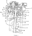
- the valve described with reference to figures 1 and 2 comprises in known manner an electromagnetic actuator (1) ensuring the angular displacement of a metal shaft (2).
- the actuator (1) comprises a metal front body (3), for example in aluminum casting or in an alloy ensuring a good thermal conduction.
- This front body (3) has cavities (4) for the circulation of a heat transfer fluid allowing the actuator to cool.
- the valve (5) comprises a metal valve body (6) defining an orifice (7) which can be closed by a shutter member (8).
- This shutter member (8) is controlled in rotation by a drive shaft (26).
- This shaft (26) is guided by a front bearing (27) and a sealed rear bearing (28).
- the mechanical connection between the actuator (1) and the valve (5) is ensured by three screws (9, 10 and 11) engaging in threaded threads (12 to 14) provided on the front body (3) of the 'actuator (1).
- the front front surface (15) of the actuator body (1) has three annular protrusions (16 to 18) surrounding the outlet of the threaded threads (12 to 14). These annular protrusions (12 to 14) make it possible to reduce the contact surfaces between the body (3) of the shareholder (1) and the body of the valve (5) and therefore to reduce thermal conduction.
- thermal insulation washers (19 to 21) are interposed between said annular protrusions (12 to 14) and the valve body (5).
- thermal insulation washers (22 to 24) are interposed between the valve body (5) and the heads of the screws (9 to 11).
- These insulating washers are for example ceramic or glass-epoxy or bakelized washers, or else any other material of low thermal conductivity.
- the rear part of the body (6) of the valve (5) has a cylindrical cavity (25) in which is housed a coupling system (41) of the shaft (2) of the actuator with the rotation shaft (26) of the valve shutter (8).
- the actuator shaft (2) and the shutter shaft (26) are aligned and coaxial. Their front ends are offset longitudinally to reserve an air space limiting the thermal conduction between the two shafts (2, 26).
- the coupling between the ends of the two shafts (2, 26) is ensured by the cooperation between a first part (29) fixed to the end of one of said shafts (2), engaged in a diametral groove formed in a second complementary piece (30) fixed to the end of the other of said shafts.
- the first part (29) and / or the second part (30) are made of a thermally insulating material.
- the second part (30) has a cup shape, the bottom of which has a cross section inscribed in a diameter at least twice as much, and typically three times, as large as the diameter of the valve rotation shaft (26).
- the second part has a transverse groove to allow the coupling of the first part (29).
- the bottom of the second part (30) makes it possible to screen the rise of the hot gases towards the actuator.
- the cut shape makes it possible to impart compactness to the valve while limiting the transfer of hot gases and ensuring good mechanical connection.
- Coupling can also be achieved by an Oldham seal, used in an unusual way for two axes almost aligned and not strongly offset.
- This coupling mode providing for a part engaged in a complementary groove makes it possible to absorb small axial shifts between the two shafts (2, 26) and above all to thermally isolate the two shafts.
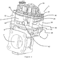
- the figure 3 shows an alternative embodiment distinguished by the present of a plate (31) formed by a thin sheet placed between the valve (5) and the actuator (1).
- the front body (3) of the actuator (1) has cylindrical columns (32 to 34) crossed by screws (35 to 37) ensuring the connection with the body (6) of the valve.
- Thermally insulating spacers (38 to 40) are interposed between the end of the columns (32 to 34) and the sheet (31).
- the sheet (31) consists of two metal sheets separated by an air space. It reflects the thermal radiation emitted by the valve (5). It is pierced by a light for the passage of the shaft (2) of the actuator.
- This upper body which is weakly thermally conductive makes it possible to limit the residual thermal transmission between the shaft (2) and the actuator, and in particular the electronic circuit fitted to the actuator.
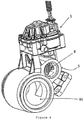
- the figure 4 presents another embodiment specifically dedicated to a discharge valve of a conduit main (44), also commonly known as a waste-gate.
- a discharge valve of a conduit main (44) also commonly known as a waste-gate.
- the actuator (1) which rotates a shutter member (8), regulating the opening of the valve (5) serving as a diversion conduit for the hot fluid of the main duct (44).
Landscapes
- Engineering & Computer Science (AREA)
- General Engineering & Computer Science (AREA)
- Mechanical Engineering (AREA)
- Chemical & Material Sciences (AREA)
- Combustion & Propulsion (AREA)
- Physics & Mathematics (AREA)
- Electromagnetism (AREA)
- Health & Medical Sciences (AREA)
- Toxicology (AREA)
- Electrically Driven Valve-Operating Means (AREA)
- Details Of Valves (AREA)
- Lift Valve (AREA)
Description
- La présente invention concerne le domaine des vannes électromagnétiques pour des fluides chauds. Elle concerne plus particulièrement des vannes pour des applications automobiles, notamment des vannes de recirculation de gaz d'échappement. Elle n'est toutefois pas limitée à des applications automobiles et concerne plus généralement des vannes pour commander la circulation de fluides gazeux ou éventuellement liquides, à des températures élevées, typiquement à plus de 200°C, et pouvant atteindre, pour des gaz d'échappement, 700°C.
- On connaît dans l'état de la technique une première famille de solutions où la liaison entre l'arbre de commande de l'organe d'obturation de la vanne, et l'actionneur, se fait par l'intermédiaire de leviers permettant de créer une isolation thermique par la distance entre la vanne soumise à des températures très élevées, et l'actionneur dont la température doit rester modérée. Ces solutions présentent de nombreux inconvénients. Elles impliquent l'utilisation de nombreuses pièces mécaniques pour assurer la transmission. Ces pièces sont soumises à des températures élevées, entraînant des dilatations difficiles à maîtriser. Elles se traduisent aussi par une usure accélérée, résultant des efforts radiaux s'exerçant sur les éléments de transmission. La demande
EP2044354 présente un exemple de réalisation. - Une deuxième famille de solution prévoit une liaison mécanique directe entre l'organe d'obturation et l'arbre de sortie de l'actionneur, et des moyens de refroidissement permettant de maintenir la température de l'actionneur à des conditions compatibles avec les contraintes des composants électroniques et électromécaniques. Par contre, ces solutions évitent les inconvénients exposés pour la première famille de solution.
- Les solutions de l'art antérieur, notamment celles prévoyant une liaison mécanique directe entre l'organe d'obturation et l'actionneur, présentent un inconvénient lié aux contraintes antinomiques sur le plan mécanique et sur le plan thermique. La demande de brevet
WO2012038351 décrit à ce titre une vanne papillon piloté par un motoréducteur. - Pour assurer un couplage mécanique satisfaisant, permettant de transmettre le couple de rotation sans jeu, et de manière fiable, on utilise un axe commun à l'actionneur et à l'organe d'obturation, ou deux axes alignés et emboités, par exemple accouplés par une liaison rigide, par exemple des arbres cannelés. La conséquence est une transmission thermique élevée, et le transfert de la chaleur de la vanne vers l'actionneur. Pour compenser cet effet, on a cherché dans l'art antérieur à refroidir une partie de l'actionneur, par exemple par un circuit de refroidissement.
- Beaucoup de solutions de l'art antérieur visent à augmenter la transmission de chaleur venant de la vanne vers des zones refroidies de l'actionneur, qui permettent d'évacuer la chaleur.
- Ces solutions conduisent à des compromis peu satisfaisants : en effet, la vanne est conçue pour fonctionner à des températures nominales élevées, et la liaison thermique avec des zones refroidies ne présente peu d'intérêt, dans la mesure où le fluide circule à sa température nominale. Elles entraînent aussi des gradients thermiques élevés, dans un espace relativement réduit, entre le fluide chaud et le circuit de refroidissement.
- Afin de concilier une liaison mécanique efficace avec un isolement thermique, on a proposé dans l'état de la technique une vanne décrite dans la demande de brevet
US2008017816 . Ce brevet décrit une vanne d'échappement comprend un corps de soupape, une soupape supportée par un arbre à l'intérieur du corps de soupape, et un actionneur qui entraîne l'arbre pour déplacer la valve par rapport au corps de soupape. - Le brevet
US8480054 décrit une autre solution connue d'accouplement d'arbre rigide en torsion et thermiquement isolant, avec de multiples degrés de liberté pour autoriser le désalignement. - Le dispositif d'accouplement permet de réduire le transfert de chaleur et d'isolation de vibrations entre l'actionneur et la vanne.
- Le dispositif d'accouplement comprend généralement un arbre d'accouplement accouplé en rotation à ses extrémités opposées aux arbres d'entrée et de sortie par des mécanismes à ressort de torsion.
- Les mécanismes à ressort de torsion comprennent des étriers de blocage en rotation de l'arbre d'accouplement des arbres d'entrée et de sortie. Les mécanismes à ressort de torsion permettent une gamme limitée de déplacement axial et de pivotement entre l'arbre d'accouplement et des arbres d'entrée et de sortie et sont pré-chargés pour éviter l'hystérésis de rotation de la vanne.
- Le brevet américain
US6598619 décrit également une soupape qui comprend un élément de fermeture, un dispositif à force motrice, un élément d'accouplement, et un élément d'espacement. - Le corps définit un passage d'écoulement qui est disposé le long d'un axe longitudinal. L'élément de fermeture est disposé dans le passage d'écoulement et comprend un premier arbre qui se prolonge le long d'un premier axe qui est oblique par rapport à l'axe longitudinal.
- L'élément de fermeture peut tourner sur le premier axe entre une première position qui empêche sensiblement l'écoulement à travers le passage d'écoulement et une seconde position qui permet généralement écoulement à travers le passage d'écoulement.
- Le moteur fait tourner l'élément de fermeture entre la première position et la seconde position, et comprend un second arbre qui peut tourner sur un deuxième axe.
- L'élément de couplage reliant les premier et second arbres pour transmettre la rotation du dispositif à l'élément de fermeture. L'élément de couplage est élastique par rapport aux premier et second arbres. L'élément d'espacement isole le dispositif par rapport à la paroi, et définit en général un volume qui contient l'élément d'accouplement.
- On connaît aussi les brevets
PCT WO2013/021133 décrivant un dispositif de dosage comprenant un corps de vanne muni d'un clapet adapté pour se déplacer entre une position de fermeture et une position d'ouverture, un axe de transmission ayant une première extrémité reliée au clapet et une seconde extrémité reliée à un élément de came, un actionneur électrique rotatif comprenant un ensemble statorique et un ensemble rotorique rotatif autour d'un axe de rotation. L'ensemble rotorique comprend une culasse magnétique portant un aimant rotorique et en outre un galet fixé sur la culasse magnétique excentré par rapport à l'axe de rotation et mobile dans l'élément de came de sorte à transformer le mouvement rotatif de l'ensemble rotorique en un mouvement de l'axe de transmission. - On connaît encore la demande de brevet allemand
DE10344218 ouEP 1431638 décrivant d'autres solutions de l'art antérieur. - Les inconvénients de ces solutions connues est que la transmission thermique est certes réduite au niveau des axes, mais subsistent par les liaisons entre le corps de l'actionneur et le corps de la vanne. Ces deux parties sont reliées par des boulons et par des surfaces adjacentes assurant un couplage thermique.
- Si au contraire, la vanne et l'actionneur sont éloignés, le problème est celui de l'encombrement de l'ensemble. Pour permettre une bonne intégration dans un véhicule, il est nécessaire que la vanne soit compacte et ne présente pas deux parties distinctes éloignées l'une de l'autre. L'homme du métier est donc confronté à un dilemme : pour répondre à la contrainte thermique, il est conduit à éloigner la vanne où circulent les gaz chaud de l'actionneur électromagnétique.
- Mais pour répondre à la contrainte de compacité, il est au contraire conduit à rapprocher ces deux parties.
- L'invention vise à résoudre ces problèmes en prenant le contrepied des solutions de l'art antérieur. Elle vise non pas à gérer la conduction thermique entre la vanne et le circuit de gaz chauds, et une zone refroidie liée de manière rigide, mais à dissocier ces deux zones tout en préservant un couplage mécanique efficace et robuste, avec une compacité.
- Elle permet ainsi d'optimiser la conception de la vanne d'une part, et de la partie actionneur d'autre part. La vanne est conçue pour fonctionner à des températures élevées, sans que l'on cherche à la refroidir ni même à empêcher absolument les fuites de fluides chauds.
- L'actionneur, de son côté, est conçu pour fonctionner à une température nominale compatible avec ses composants électroniques, magnétiques et électriques, sans qu'il ne soit nécessaire d'organiser la transmission des calories venant du couplage thermique avec la vanne par un axe commun.
- L'un des buts essentiels de l'invention est de concilier le découplage thermique, la robustesse de la transmission du couple et la compacité de l'ensemble formé par l'actionneur et la vanne.
- A cet effet, l'invention concerne selon son acception la plus générale une vanne de circulation de fluides chauds électro-commandée constituée d'un actionneur électromagnétique et d'une vanne, ladite vanne présentant un orifice muni d'un organe d'obturation mobile entraîné par un arbre de rotation perpendiculaire à l'axe dudit orifice, ledit actionneur électromagnétique entraînant la rotation dudit arbre, l'arbre de sortie dudit actionneur étant sensiblement coaxial avec ledit arbre de rotation, l'extrémité frontale de l'arbre de rotation et l'extrémité frontale de l'arbre de sortie ne sont pas en contact direct, l'accouplement entre ledit arbre de rotation de la vanne et ledit arbre de sortie de l'actionneur est assuré par un organe d'accouplement placé entre l'extrémité frontale dudit arbre de sortie et l'extrémité frontale dudit arbre, ledit organe d'accouplement présentant des moyens de transmission de couple de rotation avec une tolérance de désalignement entre l'arbre de sortie d'une part et l'arbre de rotation de la vanne d'autre part, ladite vanne étant caractérisée par des moyens de liaison mécaniques isolants thermiquement entre des zones périphériques du corps de l'actionneur et le corps de la vanne, et en ce que l'organe d'accouplement est constitué d'une première pièce de section transversale fixée à l'extrémité de l'un desdites arbres, sans que la forme de la section soit limitative, engagée dans une rainure transversale formée dans une seconde pièce complémentaire fixée à l'extrémité de l'autre desdites arbres. La première pièce et/ou la seconde pièce sont réalisées en un matériau isolant thermiquement. Leurs forme et section peut varier mais la seconde pièce, reliant l'arbre portant l'organe d'obturation, est de section transversale pleine, cette section étant avantageusement inscrite dans un diamètre significativement supérieur (au moins deux fois supérieur et typiquement trois fois supérieur) à celui de l'arbre portant l'organe d'obturation, afin de former une barrière thermique efficace aux gaz chauds pouvant remonter par l'arbre portant l'organe d'obturation.
- On entend par « section inscrite », une section de forme extérieure quelconque, préférentiellement circulaire, ayant plusieurs points, préférentiellement tous ses points, de tangence avec le diamètre dans lequel elle est inscrite.
- On entend par «isolant thermiquement » une conductivité thermique inférieure à 30 (W·m-1·K-1). A titre d'exemple non limitatif, on pourra choisir de l'acier inoxydable (18 % Chrome, 8 % Nickel) ou bien encore de la céramique.
- Selon une variante, la vanne comporte au moins une tôle, ou plaque, placée entre la surface frontale de la vanne et la surface frontale de l'actionneur.
- Avantageusement, elle comporte au moins deux tôles séparées par une lame d'isolant, placées entre la surface frontale de la vanne et la surface frontale de l'actionneur.
- Selon une première variante de réalisation, ledit organe d'accouplement est réalisé en acier inoxydable.
- Selon une deuxième variante, ledit organe d'accouplement est réalisé en céramique.
- Selon une troisième variante, ledit organe d'accouplement est un joint de Oldham.
- Avantageusement, l'actionneur présente au moins trois zones de liaison périphériques pour la fixation sur la vanne.
- Selon un mode de réalisation préférentiel, ledit organe d'accouplement présente une surface discale de déflexion dirigée vers la surface frontale de la vanne.
- La présente invention sera mieux comprise à la lecture de la description qui suit concernant un exemple non limitatif de réalisation d'une vanne de circulation selon l'invention, se référant aux dessins annexés où :
- la
figure 1 représente une vue en coupe d'un premier exemple de réalisation, - la
figure 2 représente une vue en perspective du premier exemple de réalisation, - la
figure 3 représente une vue en coupe d'un deuxième exemple de réalisation, - la
figure 4 représente une vue en perspective d'un troisième exemple de réalisation, - la
figure 5 représente une vue isolée de l'organe d'accouplement avec l'organe d'obturation. - La vanne décrit en référence aux
figures 1 et2 comporte de manière connue actionneur électromagnétique (1) assurant le déplacement angulaire d'un arbre (2) métallique. Dans l'exemple décrit, reprenant un exemple de réalisation d'une vanne de recirculation de gaz d'échappement, l'actionneur (1) comprend un corps avant (3) métallique, par exemple en moulage d'aluminium ou en alliage assurant une bonne conduction thermique. Ce corps avant (3) présente des cavités (4) pour la circulation d'un fluide caloporteur permettant d'assurer le refroidissement de l'actionneur. - La vanne (5) comprend un corps de vanne (6) métallique définissant un orifice (7) qui peut être obturé par un organe d'obturation (8). Cet organe d'obturation (8) est commandé en rotation par un arbre d'entraînement (26). Cet arbre (26) est guidé par un palier avant (27) et un palier arrière (28) étanchéifié.
- La liaison mécanique entre l'actionneur (1) et la vanne (5) est assuré par trois vis (9, 10 et 11) s'engageant dans des taraudages filetés (12 à 14) prévus sur le corps avant (3) de l'actionneur (1).
- La surface frontale avant (15) du corps de l'actionneur (1) présente trois protubérances annulaires (16 à 18) entourant le débouché des taraudages filetés (12 à 14). Ces protubérances annulaires (12 à 14) permettent de réduire les surfaces de contact entre le corps (3) de l'actionnaire (1) et le corps de la vanne (5) et donc de réduire la conduction thermique.
- Pour réduire encore la conduction thermique entre le corps de la vanne (5) et le corps de l'actionneur (1), des rondelles d'isolation thermiques (19 à 21) sont interposées entre lesdites protubérances annulaires (12 à 14) et le corps de la vanne (5). De même des rondelles d'isolation thermiques (22 à 24) sont interposées entre le corps de la vanne (5) et les têtes des vis (9 à 11).
- Ces rondelles isolantes sont par exemples des rondelles céramiques ou verre-époxy, ou bakelisées, ou encore en toute autre matériau de faible conductivité thermique.
- La partie arrière du corps (6) de la vanne (5) présente une cavité cylindrique (25) dans laquelle est logé un système d'accouplement (41) de l'arbre (2) de l'actionneur avec l'arbre de rotation (26) de l'obturateur (8) de la vanne.
- L'arbre (2) de l'actionneur et l'arbre (26) de l'obturateur sont alignés et coaxiaux. Leurs extrémités frontales sont décalées longitudinalement pour réserver un espace d'air limitant la conduction thermique entre les deux arbres (2, 26).
- L'accouplement entre les extrémités des deux arbres (2, 26) est assuré par la coopération entre une première pièce (29) fixée à l'extrémité de l'un desdites arbres (2), engagée dans une rainure diamétrale formée dans une seconde pièce (30) complémentaire fixée à l'extrémité de l'autre desdites arbres. La première pièce (29) et/ou la seconde pièce (30) sont réalisées en un matériau isolant thermiquement.
- La seconde pièce (30) présente une forme de coupe dont le fond présente une section transversale inscrite dans un diamètre au moins deux fois supérieur, et typiquement trois fois supérieur, au diamètre de l'arbre de rotation de la vanne (26). La seconde pièce présente une rainure transversale pour permettre l'accouplement de la première pièce (29).
- Le fond de la seconde pièce (30) permet de faire écran à la remontée des gaz chauds vers l'actionneur. La forme de coupe permet de conférer une compacité à la vanne tout en limitant le transfert de gaz chauds et en assurant une bonne liaison mécanique.
- L'accouplement peut aussi être réalisé par un joint d'Oldham, utilisé de manière inhabituelle pour deux axes quasiment alignés et non pas fortement décalés.
- Ce mode d'accouplement prévoyant une pièce engagée dans une rainure complémentaire permet d'absorber de faibles décalages axiaux entre les deux arbres (2, 26) et surtout d'isoler thermiquement les deux arbres.
- La
figure 3 représente une variante de réalisation se distinguant par la présente d'une plaque (31) formée par une tôle fine placée entre la vanne (5) et l'actionneur (1). - Le corps avant (3) de l'actionneur (1) présente des colonnes (32 à 34) cylindriques traversées par vis (35 à 37) assurant la liaison avec le corps (6) de la vanne. Des entretoises isolantes thermiquement (38 à 40) sont interposées entre l'extrémité des colonnes (32 à 34) et la tôle (31).
- La tôle (31) est constituée de deux feuilles métalliques séparées par une lame d'air. Elle réfléchit le rayonnement thermique émis par la vanne (5). Elle est percée par une lumière pour le passage de l'arbre (2) de l'actionneur.
- Elle peut être légèrement incurvée pour former un bouclier thermique concave, vu du côté de la vanne (5).
- Dans cet exemple de réalisation, l'actionneur (1) comporte :
- un corps inférieur (3) métallique, avec un circuit de refroidissement débouchant sur un embout (42), et
- un corps supérieur (43) en un matériau faiblement conducteur thermiquement, par exemple une matière plastique.
- Ce corps supérieur faiblement conducteur thermiquement permet de limiter la transmission thermique résiduelle entre l'arbre (2) et l'actionneur, et notamment le circuit électronique équipant l'actionneur.
- La
figure 4 présente un autre mode de réalisation spécifiquement dédié à une vanne de décharge d'un conduit principal (44), aussi communément appelé « waste-gate ». On y retrouve les éléments constitutifs de l'invention avec notamment l'actionneur (1) qui déplace en rotation un organe d'obturation (8), régulant l'ouverture de la vanne (5) servant de conduit de diversion du fluide chaud du conduit principal (44).
Claims (11)
- Vanne de circulation de fluides chauds électro-commandée constituée d'un actionneur électromagnétique (1) et d'une vanne (5), ladite vanne (5) présentant un orifice (7) muni d'un organe d'obturation (8) mobile entraîné par un arbre (26) de rotation perpendiculaire à l'axe dudit orifice, ledit actionneur électromagnétique (1) entraînant la rotation dudit arbre (26), l'arbre de sortie (2) dudit actionneur (1) étant sensiblement coaxial avec ledit arbre de rotation (26), l'extrémité frontale de l'arbre de rotation (26) et l'extrémité frontale de l' arbre de sortie (2) ne sont pas en contact direct, l'accouplement entre ledit arbre de rotation (26) de la vanne et ledit arbre de sortie (2) de l'actionneur est assuré par un organe d'accouplement (41) placé entre l'extrémité frontale dudit arbre de sortie (2) et l'extrémité frontale dudit arbre (26), ledit organe d'accouplement (41) présentant des moyens de transmission de couple de rotation avec une tolérance de désalignement entre l'arbre de sortie (2) d'une part et l'arbre de rotation de la vanne (26) d'autre part, ladite vanne étant caractérisée par des moyens de liaison mécaniques (19 à 21 ; 38 à 40 ; 22 à 24) isolants thermiquement entre des zones périphériques du corps de l'actionneur et le corps de la vanne, et en ce que l'organe d'accouplement (41) est constitué d'une première pièce (29) fixée à l'extrémité de l'un desdites arbres (2), engagée dans une rainure transversale formée dans une seconde pièce (30) complémentaire fixée à l'extrémité de l'autre desdites arbres (26), ladite seconde pièce (30) ayant une section transversale pleine.
- Vanne électro-commandée selon la revendication 1 caractérisée en ce que ladite première pièce (29) et/ou ladite seconde pièce (30) sont réalisées en un matériau isolant thermiquement et la seconde pièce (30) présente une section inscrite dans un diamètre au moins deux fois supérieur à celui de l'arbre de rotation (26), typiquement trois fois supérieur.
- Vanne électro-commandée selon la revendication 2 caractérisée en ce que la seconde pièce présente une forme extérieure circulaire.
- Vanne électro-commandée selon la revendication 1 caractérisée en ce que ledit organe d'accouplement (41) est réalisé au moins en partie en un matériau de faible conductivité thermique.
- Vanne électro-commandée selon l'une des revendications 1 à 4 caractérisée en ce qu'elle comporte au moins une tôle (31) placée entre la surface frontale de la vanne (5) et la surface frontale de l'actionneur (1).
- Vanne électro-commandée selon la revendication 5 caractérisée en ce qu'elle comporte au moins deux tôles (31) séparées par une lame d'isolant, placées entre la surface frontale de la vanne et la surface frontale de l'actionneur.
- Vanne électro-commandée selon la revendication 1 caractérisée en ce que ledit organe d'accouplement (41) est réalisé en partie en acier inoxydable.
- Vanne électro-commandée selon la revendication 1 caractérisée en ce que ledit organe d'accouplement (41) est réalisé au moins en partie en céramique.
- Vanne électro-commandée selon la revendication 1 caractérisée en ce que ledit organe d'accouplement (41) est un joint de Oldham.
- Vanne électro-commandée selon la revendication 1 caractérisée en ce que l'actionneur présente au moins trois zones de liaison périphériques pour la fixation sur la vanne.
- Vanne électro-commandée selon la revendication 1 caractérisée en ce que ledit organe d'accouplement présente une surface discale de déflexion dirigée vers la surface frontale de la vanne.
Applications Claiming Priority (2)
| Application Number | Priority Date | Filing Date | Title |
|---|---|---|---|
| FR1550882A FR3032253B1 (fr) | 2015-02-04 | 2015-02-04 | Vanne electro-commandee pour fluide chaud |
| PCT/EP2016/052442 WO2016124720A1 (fr) | 2015-02-04 | 2016-02-04 | Vanne electro-commandee pour fluide chaud |
Publications (2)
| Publication Number | Publication Date |
|---|---|
| EP3254006A1 EP3254006A1 (fr) | 2017-12-13 |
| EP3254006B1 true EP3254006B1 (fr) | 2020-06-17 |
Family
ID=53200099
Family Applications (1)
| Application Number | Title | Priority Date | Filing Date |
|---|---|---|---|
| EP16705455.0A Active EP3254006B1 (fr) | 2015-02-04 | 2016-02-04 | Vanne electro-commandee pour fluide chaud |
Country Status (4)
| Country | Link |
|---|---|
| US (1) | US10641408B2 (fr) |
| EP (1) | EP3254006B1 (fr) |
| FR (1) | FR3032253B1 (fr) |
| WO (1) | WO2016124720A1 (fr) |
Families Citing this family (11)
| Publication number | Priority date | Publication date | Assignee | Title |
|---|---|---|---|---|
| DE102016112694A1 (de) | 2016-07-11 | 2018-01-11 | Faurecia Emissions Control Technologies, Germany Gmbh | Ventilbetätigungsvorrichtung |
| US20180030936A1 (en) * | 2016-08-01 | 2018-02-01 | G.W. Lisk Company, Inc. | Exhaust gas recirculation valve having crowned spline |
| FR3059070B1 (fr) | 2016-11-24 | 2018-11-02 | Moving Magnet Technologies | Vanne de circulation d’air |
| FR3062701B1 (fr) | 2017-02-06 | 2019-06-07 | Mmt ag | Vanne motorisee a boisseau |
| FR3065507B1 (fr) * | 2017-04-21 | 2019-06-28 | Valeo Systemes De Controle Moteur | Dispositif d'entrainement en rotation, notamment pour une vanne, comprenant un engrenage et une jupe de protection contre la propagation des particules d'usure de l'engrenage |
| DE102017116423A1 (de) * | 2017-07-20 | 2019-01-24 | Pierburg Gmbh | Klappenvorrichtung |
| FR3074872B1 (fr) | 2017-12-08 | 2019-11-01 | Moving Magnet Technologies | Vanne de reglage compacte |
| DE102018214069A1 (de) * | 2018-08-21 | 2020-02-27 | Continental Automotive Gmbh | Ventil zur Steuerung von Abgas oder Frischluft in einer Antriebseinheit eines Kraftfahrzeuges oder Generators |
| FR3087244B1 (fr) * | 2018-10-11 | 2021-01-15 | Faurecia Systemes Dechappement | Vanne d'echappement |
| US11560964B2 (en) | 2020-08-21 | 2023-01-24 | Acist Medical Systems, Inc. | Valve actuation device coupling |
| IT202200004115A1 (it) * | 2022-03-04 | 2023-09-04 | Marelli Europe Spa | Valvola a farfalla motorizzata e raffreddata per un condotto di scarico |
Family Cites Families (33)
| Publication number | Priority date | Publication date | Assignee | Title |
|---|---|---|---|---|
| USRE30135E (en) * | 1973-02-09 | 1979-11-06 | Amelia Inc. | Electric fail-safe actuator |
| CH579713A5 (en) * | 1973-10-17 | 1976-09-15 | Inventa Ag | Fluid medium drive arrangement - has expandable cells carried on shaft eccentrically mounted within cylindrical housing |
| DE4302666A1 (de) * | 1993-01-30 | 1994-08-04 | Abb Management Ag | Schnellschlussklappe |
| US5460146A (en) * | 1994-01-12 | 1995-10-24 | Robertshaw Controls Company | Solenoid activated exhaust gas recirculation valve |
| US6079210A (en) * | 1998-07-16 | 2000-06-27 | Woodward Governor Company | Continuously variable electrically actuated flow control valve for high temperature applications |
| JP3816275B2 (ja) * | 1999-08-04 | 2006-08-30 | 株式会社キッツ | バタフライ弁 |
| US6299130B1 (en) * | 1999-10-14 | 2001-10-09 | Siemens Canada Limited | EEGR valve with flexible bearing |
| CN1147672C (zh) * | 2000-04-27 | 2004-04-28 | 吴龙洙 | 电动球形阀 |
| DE10101412B4 (de) * | 2001-01-13 | 2014-05-28 | Pierburg Gmbh | Abgasrückführeinrichtung für eine Brennkraftmaschine |
| US6568417B2 (en) * | 2001-04-17 | 2003-05-27 | Intel Corporation | Throttle valve assembly |
| US6676109B2 (en) * | 2001-05-22 | 2004-01-13 | Kitz Corporation | Rotary valve |
| US6598619B2 (en) * | 2001-09-21 | 2003-07-29 | Siemens Vdo Automotive, Inc. | Exhaust gas regulator including a resilient coupling |
| JP2004162679A (ja) * | 2002-11-08 | 2004-06-10 | Aisan Ind Co Ltd | 電動式スロットルボデー |
| FR2849144B1 (fr) | 2002-12-18 | 2005-10-21 | Snecma Moteurs | Dispositif de vanne cryogenique a actionneur pneumatique |
| US20040262556A1 (en) * | 2003-01-17 | 2004-12-30 | Everingham Gary Michael | Exhaust gas recirculation valve having a rotary motor |
| EP1598538B1 (fr) * | 2003-03-07 | 2008-08-20 | Denso Corporation | Dispositif de commande électronique de papillon |
| FR2857719B1 (fr) * | 2003-07-17 | 2006-02-03 | Snecma Moteurs | Dispositif de vanne a longue course de regulation |
| DE10344218B4 (de) * | 2003-09-22 | 2014-10-23 | Mahle Filtersysteme Gmbh | Abgasrückführungsventil |
| JP4383933B2 (ja) * | 2004-03-15 | 2009-12-16 | 三菱電機株式会社 | 電動制御弁の出力軸接続構造の製造方法 |
| US7472885B2 (en) * | 2006-03-06 | 2009-01-06 | Honeywell International, Inc. | Compact, lightweight cabin pressure control system butterfly outflow valve with redundancy features |
| US7581710B2 (en) | 2006-07-24 | 2009-09-01 | Emcon Technologies Llc | Thermally isolated actuator with temporary contacting linkage for an exhaust valve |
| US20080017816A1 (en) | 2006-07-24 | 2008-01-24 | Arvin Technologies, Inc. | Thermal isolator for actuator and valve assembly |
| US7740228B2 (en) * | 2006-08-09 | 2010-06-22 | Hamilton Sundstrand Corporation | Valve assembly including a torsion spring coupling a valve shaft and actuator shaft |
| DE102006048678B4 (de) * | 2006-10-14 | 2011-11-17 | Pierburg Gmbh | Kupplungsvorrichtung |
| KR101057067B1 (ko) * | 2008-02-04 | 2011-08-16 | 캄텍주식회사 | 차량용 이지알 밸브 |
| US8480054B2 (en) * | 2008-05-30 | 2013-07-09 | Woodward, Inc. | Tortionally stiff, thermally isolating shaft coupling with multiple degrees of freedom to accommodate misalignment |
| GB0910082D0 (en) * | 2009-06-11 | 2009-07-22 | Norgren Ltd C A | Two-part valve |
| US8146886B2 (en) * | 2009-08-04 | 2012-04-03 | Honeywell International Inc. | High accuracy, zero backlash rotary-to-linear electromechanical actuator |
| WO2012038352A1 (fr) | 2010-09-20 | 2012-03-29 | Norgren Gmbh | Vanne papillon haute température |
| EP2655835B1 (fr) * | 2010-12-20 | 2017-05-17 | Continental Automotive GmbH | Unité de soupape |
| FR2978998B1 (fr) | 2011-08-08 | 2013-07-26 | Sonceboz Automotive Sa | Dispositif de dosage compact |
| DE102013015138A1 (de) * | 2013-09-13 | 2015-03-19 | Man Truck & Bus Ag | Vorrichtung zur Ansteuerung einer Drosselklappe, insbesondere einer Drosselklappe einer Ansauganlage einer Brennkraftmaschine |
| US10060311B2 (en) * | 2016-08-17 | 2018-08-28 | Hyundai Motor Company | Electric valve |
-
2015
- 2015-02-04 FR FR1550882A patent/FR3032253B1/fr not_active Expired - Fee Related
-
2016
- 2016-02-04 EP EP16705455.0A patent/EP3254006B1/fr active Active
- 2016-02-04 US US15/548,610 patent/US10641408B2/en active Active
- 2016-02-04 WO PCT/EP2016/052442 patent/WO2016124720A1/fr active Application Filing
Non-Patent Citations (1)
| Title |
|---|
| None * |
Also Published As
| Publication number | Publication date |
|---|---|
| FR3032253B1 (fr) | 2017-01-20 |
| US20170370493A1 (en) | 2017-12-28 |
| WO2016124720A1 (fr) | 2016-08-11 |
| US10641408B2 (en) | 2020-05-05 |
| FR3032253A1 (fr) | 2016-08-05 |
| EP3254006A1 (fr) | 2017-12-13 |
Similar Documents
| Publication | Publication Date | Title |
|---|---|---|
| EP3254006B1 (fr) | Vanne electro-commandee pour fluide chaud | |
| FR2966873A1 (fr) | Dispositif de recuperation de chaleur pour ligne d'echappement | |
| FR2943114A1 (fr) | Vanne pour ligne d'echappement | |
| CA2629789C (fr) | Procede et installation de controle non destructif par courants de foucault, a etalonnage automatique | |
| EP1985834B1 (fr) | Vanne à clapet pour un système de refroidissement dans une turbomachine | |
| EP1717432B1 (fr) | Tuyère d'éjection orientable d'un moteur d'aéronef | |
| EP2006585B1 (fr) | Vanne de régulation | |
| EP3230633B1 (fr) | Vanne de dosage adaptée aux hautes pressions | |
| FR2989998A1 (fr) | Dispositif de recuperation de chaleur pour ligne d'echappement | |
| WO2020254772A1 (fr) | Vanne de réglage compacte | |
| FR3069609B1 (fr) | Vanne de dosage de fluide | |
| FR2937679A1 (fr) | Dispositif de prelevement d'air de refroidissement dans une turbomachine | |
| FR2790073A1 (fr) | Echangeur thermique a plaques, a vanne integree | |
| FR2962511A1 (fr) | Vanne perfectionnee, et application | |
| FR3082562A1 (fr) | Anneau de commande de portes de decharge pour une turbomachine d'aeronef et turbomachine le comportant | |
| WO2015145027A1 (fr) | Interface améliorée pour une vanne de conduit de fluide cryogenique. | |
| EP3647636B1 (fr) | Vanne de régulation d'un flux de fluide equipée d'un actionneur électrique et système comprenant une telle vanne | |
| EP1607818B1 (fr) | Vanne thermostatistique pour un circuit de refroidissement | |
| EP2895728B1 (fr) | Vanne de circulation d'un fluide, en particulier gaz d'echappement recircule | |
| FR2975454A1 (fr) | Palier articule et turbocompresseur de gaz d'echappement equipe d'un tel palier | |
| EP1108929B1 (fr) | Organe de réglage du débit d'un fluide | |
| EP3645906B1 (fr) | Pompe hydraulique pour interface de connexion hydraulique d'un mecanisme d'embrayage | |
| FR3069597A1 (fr) | Actionneur d'embrayage | |
| WO2020099775A1 (fr) | Systeme de controle de debit d'un fluide avec capteur de position lineaire integre | |
| FR3065507B1 (fr) | Dispositif d'entrainement en rotation, notamment pour une vanne, comprenant un engrenage et une jupe de protection contre la propagation des particules d'usure de l'engrenage |
Legal Events
| Date | Code | Title | Description |
|---|---|---|---|
| STAA | Information on the status of an ep patent application or granted ep patent |
Free format text: STATUS: THE INTERNATIONAL PUBLICATION HAS BEEN MADE |
|
| PUAI | Public reference made under article 153(3) epc to a published international application that has entered the european phase |
Free format text: ORIGINAL CODE: 0009012 |
|
| STAA | Information on the status of an ep patent application or granted ep patent |
Free format text: STATUS: REQUEST FOR EXAMINATION WAS MADE |
|
| 17P | Request for examination filed |
Effective date: 20170804 |
|
| AK | Designated contracting states |
Kind code of ref document: A1 Designated state(s): AL AT BE BG CH CY CZ DE DK EE ES FI FR GB GR HR HU IE IS IT LI LT LU LV MC MK MT NL NO PL PT RO RS SE SI SK SM TR |
|
| AX | Request for extension of the european patent |
Extension state: BA ME |
|
| DAV | Request for validation of the european patent (deleted) | ||
| DAX | Request for extension of the european patent (deleted) | ||
| GRAP | Despatch of communication of intention to grant a patent |
Free format text: ORIGINAL CODE: EPIDOSNIGR1 |
|
| STAA | Information on the status of an ep patent application or granted ep patent |
Free format text: STATUS: GRANT OF PATENT IS INTENDED |
|
| INTG | Intention to grant announced |
Effective date: 20200117 |
|
| GRAS | Grant fee paid |
Free format text: ORIGINAL CODE: EPIDOSNIGR3 |
|
| GRAA | (expected) grant |
Free format text: ORIGINAL CODE: 0009210 |
|
| STAA | Information on the status of an ep patent application or granted ep patent |
Free format text: STATUS: THE PATENT HAS BEEN GRANTED |
|
| AK | Designated contracting states |
Kind code of ref document: B1 Designated state(s): AL AT BE BG CH CY CZ DE DK EE ES FI FR GB GR HR HU IE IS IT LI LT LU LV MC MK MT NL NO PL PT RO RS SE SI SK SM TR |
|
| REG | Reference to a national code |
Ref country code: GB Ref legal event code: FG4D Free format text: NOT ENGLISH |
|
| REG | Reference to a national code |
Ref country code: CH Ref legal event code: EP |
|
| REG | Reference to a national code |
Ref country code: IE Ref legal event code: FG4D Free format text: LANGUAGE OF EP DOCUMENT: FRENCH |
|
| REG | Reference to a national code |
Ref country code: DE Ref legal event code: R096 Ref document number: 602016038183 Country of ref document: DE |
|
| REG | Reference to a national code |
Ref country code: AT Ref legal event code: REF Ref document number: 1281718 Country of ref document: AT Kind code of ref document: T Effective date: 20200715 |
|
| PG25 | Lapsed in a contracting state [announced via postgrant information from national office to epo] |
Ref country code: FI Free format text: LAPSE BECAUSE OF FAILURE TO SUBMIT A TRANSLATION OF THE DESCRIPTION OR TO PAY THE FEE WITHIN THE PRESCRIBED TIME-LIMIT Effective date: 20200617 Ref country code: SE Free format text: LAPSE BECAUSE OF FAILURE TO SUBMIT A TRANSLATION OF THE DESCRIPTION OR TO PAY THE FEE WITHIN THE PRESCRIBED TIME-LIMIT Effective date: 20200617 Ref country code: LT Free format text: LAPSE BECAUSE OF FAILURE TO SUBMIT A TRANSLATION OF THE DESCRIPTION OR TO PAY THE FEE WITHIN THE PRESCRIBED TIME-LIMIT Effective date: 20200617 Ref country code: GR Free format text: LAPSE BECAUSE OF FAILURE TO SUBMIT A TRANSLATION OF THE DESCRIPTION OR TO PAY THE FEE WITHIN THE PRESCRIBED TIME-LIMIT Effective date: 20200918 Ref country code: NO Free format text: LAPSE BECAUSE OF FAILURE TO SUBMIT A TRANSLATION OF THE DESCRIPTION OR TO PAY THE FEE WITHIN THE PRESCRIBED TIME-LIMIT Effective date: 20200917 |
|
| REG | Reference to a national code |
Ref country code: LT Ref legal event code: MG4D |
|
| REG | Reference to a national code |
Ref country code: NL Ref legal event code: MP Effective date: 20200617 |
|
| PG25 | Lapsed in a contracting state [announced via postgrant information from national office to epo] |
Ref country code: BG Free format text: LAPSE BECAUSE OF FAILURE TO SUBMIT A TRANSLATION OF THE DESCRIPTION OR TO PAY THE FEE WITHIN THE PRESCRIBED TIME-LIMIT Effective date: 20200917 Ref country code: LV Free format text: LAPSE BECAUSE OF FAILURE TO SUBMIT A TRANSLATION OF THE DESCRIPTION OR TO PAY THE FEE WITHIN THE PRESCRIBED TIME-LIMIT Effective date: 20200617 Ref country code: RS Free format text: LAPSE BECAUSE OF FAILURE TO SUBMIT A TRANSLATION OF THE DESCRIPTION OR TO PAY THE FEE WITHIN THE PRESCRIBED TIME-LIMIT Effective date: 20200617 Ref country code: HR Free format text: LAPSE BECAUSE OF FAILURE TO SUBMIT A TRANSLATION OF THE DESCRIPTION OR TO PAY THE FEE WITHIN THE PRESCRIBED TIME-LIMIT Effective date: 20200617 |
|
| REG | Reference to a national code |
Ref country code: AT Ref legal event code: MK05 Ref document number: 1281718 Country of ref document: AT Kind code of ref document: T Effective date: 20200617 |
|
| PG25 | Lapsed in a contracting state [announced via postgrant information from national office to epo] |
Ref country code: NL Free format text: LAPSE BECAUSE OF FAILURE TO SUBMIT A TRANSLATION OF THE DESCRIPTION OR TO PAY THE FEE WITHIN THE PRESCRIBED TIME-LIMIT Effective date: 20200617 Ref country code: AL Free format text: LAPSE BECAUSE OF FAILURE TO SUBMIT A TRANSLATION OF THE DESCRIPTION OR TO PAY THE FEE WITHIN THE PRESCRIBED TIME-LIMIT Effective date: 20200617 |
|
| PG25 | Lapsed in a contracting state [announced via postgrant information from national office to epo] |
Ref country code: AT Free format text: LAPSE BECAUSE OF FAILURE TO SUBMIT A TRANSLATION OF THE DESCRIPTION OR TO PAY THE FEE WITHIN THE PRESCRIBED TIME-LIMIT Effective date: 20200617 Ref country code: IT Free format text: LAPSE BECAUSE OF FAILURE TO SUBMIT A TRANSLATION OF THE DESCRIPTION OR TO PAY THE FEE WITHIN THE PRESCRIBED TIME-LIMIT Effective date: 20200617 Ref country code: EE Free format text: LAPSE BECAUSE OF FAILURE TO SUBMIT A TRANSLATION OF THE DESCRIPTION OR TO PAY THE FEE WITHIN THE PRESCRIBED TIME-LIMIT Effective date: 20200617 Ref country code: SM Free format text: LAPSE BECAUSE OF FAILURE TO SUBMIT A TRANSLATION OF THE DESCRIPTION OR TO PAY THE FEE WITHIN THE PRESCRIBED TIME-LIMIT Effective date: 20200617 Ref country code: ES Free format text: LAPSE BECAUSE OF FAILURE TO SUBMIT A TRANSLATION OF THE DESCRIPTION OR TO PAY THE FEE WITHIN THE PRESCRIBED TIME-LIMIT Effective date: 20200617 Ref country code: CZ Free format text: LAPSE BECAUSE OF FAILURE TO SUBMIT A TRANSLATION OF THE DESCRIPTION OR TO PAY THE FEE WITHIN THE PRESCRIBED TIME-LIMIT Effective date: 20200617 Ref country code: RO Free format text: LAPSE BECAUSE OF FAILURE TO SUBMIT A TRANSLATION OF THE DESCRIPTION OR TO PAY THE FEE WITHIN THE PRESCRIBED TIME-LIMIT Effective date: 20200617 Ref country code: PT Free format text: LAPSE BECAUSE OF FAILURE TO SUBMIT A TRANSLATION OF THE DESCRIPTION OR TO PAY THE FEE WITHIN THE PRESCRIBED TIME-LIMIT Effective date: 20201019 |
|
| PG25 | Lapsed in a contracting state [announced via postgrant information from national office to epo] |
Ref country code: IS Free format text: LAPSE BECAUSE OF FAILURE TO SUBMIT A TRANSLATION OF THE DESCRIPTION OR TO PAY THE FEE WITHIN THE PRESCRIBED TIME-LIMIT Effective date: 20201017 Ref country code: SK Free format text: LAPSE BECAUSE OF FAILURE TO SUBMIT A TRANSLATION OF THE DESCRIPTION OR TO PAY THE FEE WITHIN THE PRESCRIBED TIME-LIMIT Effective date: 20200617 Ref country code: PL Free format text: LAPSE BECAUSE OF FAILURE TO SUBMIT A TRANSLATION OF THE DESCRIPTION OR TO PAY THE FEE WITHIN THE PRESCRIBED TIME-LIMIT Effective date: 20200617 |
|
| REG | Reference to a national code |
Ref country code: DE Ref legal event code: R097 Ref document number: 602016038183 Country of ref document: DE |
|
| PLBE | No opposition filed within time limit |
Free format text: ORIGINAL CODE: 0009261 |
|
| STAA | Information on the status of an ep patent application or granted ep patent |
Free format text: STATUS: NO OPPOSITION FILED WITHIN TIME LIMIT |
|
| PG25 | Lapsed in a contracting state [announced via postgrant information from national office to epo] |
Ref country code: DK Free format text: LAPSE BECAUSE OF FAILURE TO SUBMIT A TRANSLATION OF THE DESCRIPTION OR TO PAY THE FEE WITHIN THE PRESCRIBED TIME-LIMIT Effective date: 20200617 |
|
| 26N | No opposition filed |
Effective date: 20210318 |
|
| PG25 | Lapsed in a contracting state [announced via postgrant information from national office to epo] |
Ref country code: SI Free format text: LAPSE BECAUSE OF FAILURE TO SUBMIT A TRANSLATION OF THE DESCRIPTION OR TO PAY THE FEE WITHIN THE PRESCRIBED TIME-LIMIT Effective date: 20200617 |
|
| PG25 | Lapsed in a contracting state [announced via postgrant information from national office to epo] |
Ref country code: MC Free format text: LAPSE BECAUSE OF FAILURE TO SUBMIT A TRANSLATION OF THE DESCRIPTION OR TO PAY THE FEE WITHIN THE PRESCRIBED TIME-LIMIT Effective date: 20200617 |
|
| GBPC | Gb: european patent ceased through non-payment of renewal fee |
Effective date: 20210204 |
|
| REG | Reference to a national code |
Ref country code: BE Ref legal event code: MM Effective date: 20210228 |
|
| PG25 | Lapsed in a contracting state [announced via postgrant information from national office to epo] |
Ref country code: LU Free format text: LAPSE BECAUSE OF NON-PAYMENT OF DUE FEES Effective date: 20210204 Ref country code: LI Free format text: LAPSE BECAUSE OF NON-PAYMENT OF DUE FEES Effective date: 20210228 Ref country code: CH Free format text: LAPSE BECAUSE OF NON-PAYMENT OF DUE FEES Effective date: 20210228 |
|
| PG25 | Lapsed in a contracting state [announced via postgrant information from national office to epo] |
Ref country code: IE Free format text: LAPSE BECAUSE OF NON-PAYMENT OF DUE FEES Effective date: 20210204 Ref country code: GB Free format text: LAPSE BECAUSE OF NON-PAYMENT OF DUE FEES Effective date: 20210204 |
|
| PG25 | Lapsed in a contracting state [announced via postgrant information from national office to epo] |
Ref country code: BE Free format text: LAPSE BECAUSE OF NON-PAYMENT OF DUE FEES Effective date: 20210228 |
|
| PGFP | Annual fee paid to national office [announced via postgrant information from national office to epo] |
Ref country code: FR Payment date: 20230119 Year of fee payment: 8 |
|
| PG25 | Lapsed in a contracting state [announced via postgrant information from national office to epo] |
Ref country code: CY Free format text: LAPSE BECAUSE OF FAILURE TO SUBMIT A TRANSLATION OF THE DESCRIPTION OR TO PAY THE FEE WITHIN THE PRESCRIBED TIME-LIMIT Effective date: 20200617 |
|
| PG25 | Lapsed in a contracting state [announced via postgrant information from national office to epo] |
Ref country code: HU Free format text: LAPSE BECAUSE OF FAILURE TO SUBMIT A TRANSLATION OF THE DESCRIPTION OR TO PAY THE FEE WITHIN THE PRESCRIBED TIME-LIMIT; INVALID AB INITIO Effective date: 20160204 |
|
| PG25 | Lapsed in a contracting state [announced via postgrant information from national office to epo] |
Ref country code: MK Free format text: LAPSE BECAUSE OF FAILURE TO SUBMIT A TRANSLATION OF THE DESCRIPTION OR TO PAY THE FEE WITHIN THE PRESCRIBED TIME-LIMIT Effective date: 20200617 |
|
| PGFP | Annual fee paid to national office [announced via postgrant information from national office to epo] |
Ref country code: DE Payment date: 20240123 Year of fee payment: 9 |