EP3252919B1 - Système et procédé d'éclairage de secours - Google Patents
Système et procédé d'éclairage de secours Download PDFInfo
- Publication number
- EP3252919B1 EP3252919B1 EP17176584.5A EP17176584A EP3252919B1 EP 3252919 B1 EP3252919 B1 EP 3252919B1 EP 17176584 A EP17176584 A EP 17176584A EP 3252919 B1 EP3252919 B1 EP 3252919B1
- Authority
- EP
- European Patent Office
- Prior art keywords
- power
- lighting
- dependable
- lamp
- network
- Prior art date
- Legal status (The legal status is an assumption and is not a legal conclusion. Google has not performed a legal analysis and makes no representation as to the accuracy of the status listed.)
- Active
Links
- 238000000034 method Methods 0.000 title description 13
- 238000012544 monitoring process Methods 0.000 claims description 14
- 238000004891 communication Methods 0.000 description 7
- 238000007726 management method Methods 0.000 description 6
- 230000004075 alteration Effects 0.000 description 3
- 238000005286 illumination Methods 0.000 description 3
- 238000012986 modification Methods 0.000 description 3
- 230000004048 modification Effects 0.000 description 3
- 230000001960 triggered effect Effects 0.000 description 2
- 230000009471 action Effects 0.000 description 1
- 230000005540 biological transmission Effects 0.000 description 1
- 230000008859 change Effects 0.000 description 1
- 239000004020 conductor Substances 0.000 description 1
- 238000013500 data storage Methods 0.000 description 1
- 238000001514 detection method Methods 0.000 description 1
- 230000000694 effects Effects 0.000 description 1
- 238000005259 measurement Methods 0.000 description 1
- 230000006855 networking Effects 0.000 description 1
- 230000002093 peripheral effect Effects 0.000 description 1
- 230000008569 process Effects 0.000 description 1
- 238000012546 transfer Methods 0.000 description 1
- 239000002699 waste material Substances 0.000 description 1
Images

Classifications
-
- H—ELECTRICITY
- H02—GENERATION; CONVERSION OR DISTRIBUTION OF ELECTRIC POWER
- H02J—CIRCUIT ARRANGEMENTS OR SYSTEMS FOR SUPPLYING OR DISTRIBUTING ELECTRIC POWER; SYSTEMS FOR STORING ELECTRIC ENERGY
- H02J9/00—Circuit arrangements for emergency or stand-by power supply, e.g. for emergency lighting
- H02J9/02—Circuit arrangements for emergency or stand-by power supply, e.g. for emergency lighting in which an auxiliary distribution system and its associated lamps are brought into service
-
- H—ELECTRICITY
- H02—GENERATION; CONVERSION OR DISTRIBUTION OF ELECTRIC POWER
- H02J—CIRCUIT ARRANGEMENTS OR SYSTEMS FOR SUPPLYING OR DISTRIBUTING ELECTRIC POWER; SYSTEMS FOR STORING ELECTRIC ENERGY
- H02J9/00—Circuit arrangements for emergency or stand-by power supply, e.g. for emergency lighting
- H02J9/04—Circuit arrangements for emergency or stand-by power supply, e.g. for emergency lighting in which the distribution system is disconnected from the normal source and connected to a standby source
- H02J9/06—Circuit arrangements for emergency or stand-by power supply, e.g. for emergency lighting in which the distribution system is disconnected from the normal source and connected to a standby source with automatic change-over, e.g. UPS systems
- H02J9/061—Circuit arrangements for emergency or stand-by power supply, e.g. for emergency lighting in which the distribution system is disconnected from the normal source and connected to a standby source with automatic change-over, e.g. UPS systems for DC powered loads
-
- H—ELECTRICITY
- H02—GENERATION; CONVERSION OR DISTRIBUTION OF ELECTRIC POWER
- H02J—CIRCUIT ARRANGEMENTS OR SYSTEMS FOR SUPPLYING OR DISTRIBUTING ELECTRIC POWER; SYSTEMS FOR STORING ELECTRIC ENERGY
- H02J9/00—Circuit arrangements for emergency or stand-by power supply, e.g. for emergency lighting
- H02J9/04—Circuit arrangements for emergency or stand-by power supply, e.g. for emergency lighting in which the distribution system is disconnected from the normal source and connected to a standby source
- H02J9/06—Circuit arrangements for emergency or stand-by power supply, e.g. for emergency lighting in which the distribution system is disconnected from the normal source and connected to a standby source with automatic change-over, e.g. UPS systems
- H02J9/062—Circuit arrangements for emergency or stand-by power supply, e.g. for emergency lighting in which the distribution system is disconnected from the normal source and connected to a standby source with automatic change-over, e.g. UPS systems for AC powered loads
- H02J9/065—Circuit arrangements for emergency or stand-by power supply, e.g. for emergency lighting in which the distribution system is disconnected from the normal source and connected to a standby source with automatic change-over, e.g. UPS systems for AC powered loads for lighting purposes
-
- H—ELECTRICITY
- H05—ELECTRIC TECHNIQUES NOT OTHERWISE PROVIDED FOR
- H05B—ELECTRIC HEATING; ELECTRIC LIGHT SOURCES NOT OTHERWISE PROVIDED FOR; CIRCUIT ARRANGEMENTS FOR ELECTRIC LIGHT SOURCES, IN GENERAL
- H05B47/00—Circuit arrangements for operating light sources in general, i.e. where the type of light source is not relevant
- H05B47/10—Controlling the light source
- H05B47/105—Controlling the light source in response to determined parameters
- H05B47/11—Controlling the light source in response to determined parameters by determining the brightness or colour temperature of ambient light
-
- H—ELECTRICITY
- H05—ELECTRIC TECHNIQUES NOT OTHERWISE PROVIDED FOR
- H05B—ELECTRIC HEATING; ELECTRIC LIGHT SOURCES NOT OTHERWISE PROVIDED FOR; CIRCUIT ARRANGEMENTS FOR ELECTRIC LIGHT SOURCES, IN GENERAL
- H05B47/00—Circuit arrangements for operating light sources in general, i.e. where the type of light source is not relevant
- H05B47/10—Controlling the light source
- H05B47/105—Controlling the light source in response to determined parameters
- H05B47/115—Controlling the light source in response to determined parameters by determining the presence or movement of objects or living beings
-
- H—ELECTRICITY
- H05—ELECTRIC TECHNIQUES NOT OTHERWISE PROVIDED FOR
- H05B—ELECTRIC HEATING; ELECTRIC LIGHT SOURCES NOT OTHERWISE PROVIDED FOR; CIRCUIT ARRANGEMENTS FOR ELECTRIC LIGHT SOURCES, IN GENERAL
- H05B47/00—Circuit arrangements for operating light sources in general, i.e. where the type of light source is not relevant
- H05B47/10—Controlling the light source
- H05B47/175—Controlling the light source by remote control
- H05B47/185—Controlling the light source by remote control via power line carrier transmission
-
- H—ELECTRICITY
- H05—ELECTRIC TECHNIQUES NOT OTHERWISE PROVIDED FOR
- H05B—ELECTRIC HEATING; ELECTRIC LIGHT SOURCES NOT OTHERWISE PROVIDED FOR; CIRCUIT ARRANGEMENTS FOR ELECTRIC LIGHT SOURCES, IN GENERAL
- H05B47/00—Circuit arrangements for operating light sources in general, i.e. where the type of light source is not relevant
- H05B47/10—Controlling the light source
-
- Y—GENERAL TAGGING OF NEW TECHNOLOGICAL DEVELOPMENTS; GENERAL TAGGING OF CROSS-SECTIONAL TECHNOLOGIES SPANNING OVER SEVERAL SECTIONS OF THE IPC; TECHNICAL SUBJECTS COVERED BY FORMER USPC CROSS-REFERENCE ART COLLECTIONS [XRACs] AND DIGESTS
- Y02—TECHNOLOGIES OR APPLICATIONS FOR MITIGATION OR ADAPTATION AGAINST CLIMATE CHANGE
- Y02B—CLIMATE CHANGE MITIGATION TECHNOLOGIES RELATED TO BUILDINGS, e.g. HOUSING, HOUSE APPLIANCES OR RELATED END-USER APPLICATIONS
- Y02B20/00—Energy efficient lighting technologies, e.g. halogen lamps or gas discharge lamps
- Y02B20/40—Control techniques providing energy savings, e.g. smart controller or presence detection
Definitions
- This invention relates to systems and methods for providing state-by lighting and, more particularly, a network based distributed plug-in emergency lamp system.
- electric power provided by a utility company may be unreliable.
- buildings are typically equipped with an emergency lighting system.
- the emergency lighting system generally consists of a single (battery backup) emergency lamp that is usually placed in the living room/hall of the house. Even though the conventional emergency lamp switches ON when a power outage occurs, such conventional emergency lighting systems provide little help if the occupants the house are not in the single room in which the emergency lamp is located. This also leads to energy waste when the occupants are not in the room in which the emergency lamp is located.
- One aspect of the present invention is related to a network based distributed plug-in emergency lamp solution that can provide light backup in multiple rooms or utility areas of the building.
- the plug-in emergency lamp according to embodiments of the present invention can be used as normal lamp, has less storage and/or has intelligence to minimize the wastage of backup energy when the user is not around or when daylight is available.
- the network based distributed plug-in emergency lamps can connect a battery storage system that can be used by all the plug-in emergency lamps in the building during the power outage. Such a power sharing network helps to extend the light availability for limited period in the occupied places of building. In this way compact low cost lamps in different rooms can be combined together to give the user better performance.
- the power sharing network connects all the plug-in emergency lamps on existing AC wiring in the building during the power outage interval, identifies the available storage in each of the plug-in emergency lamps and adjusts the power resource by sending power from one plug-in emergency lamp to another to extend the light availability in the occupied spaces of building.
- the power sharing network connects all the plug-in emergency lamps with additional wiring to form a DC network, identifies the available storage in each of the plug-in emergency lamps and adjusts the power resource by sending power from one plug-in emergency lamp to another to extend the light availability in the occupied spaces of building for a predetermined time.
- the proposed invention uses the additional wiring to exchange the power as well as data between the plug-in emergency lamps during the power outages and uses a simplified the control architecture.
- an additional battery bank can be connected to the DC network to extend the light in one or more of the rooms, in case of the emergency or a planned activity. This may be done by reserving one node on DC network and connecting the additional battery bank to the (vacant) reserved node.
- various types of conventional emergency lamps can also be added and networked together with the plug-in emergency lamps.
- a grid power monitoring unit is used to communicate with all the plug-in emergency lamps to configure the network.
- the present invention is directed to a lighting network including a plurality of lighting units that can operate on AC power and DC power if the AC power is removed.
- a controller is arranged to redistribute the DC power between the plurality of lighting units.
- the lighting network also an AC power monitoring unit arranged to detect the presence or absence of the AC power. In the lighting network the controller redistributes the DC power using the same distribution path used by the AC power.
- the present application is directed to a lighting unit including a lighting emitting unit, a driver coupled to the lighting emitting unit and an AC/DC converter arranged to supply power to the driver.
- a DC battery unit (14) is also coupled to the driver and arranged to supply power to the driver if the AC/DC converter cannot supply the power to the driver.
- a controller (15) arranged to request additional power if the power from the DC battery unit is running low.
- the lighting unit also includes a bypass switch that is used to switch, under control from the controller, to the DC power when the AC power is not available.
- the lighting unit further includes a DC input path to receive the additional power.
- Another example of the present application is directed to a method for supplying DC back up lighting for an area.
- the method includes the steps of determining if an AC power outage has occurred and determining if the area was illuminated before the AC power outage occurred. Based upon the determinations, if the area was not illuminated the DC back up lighting is not supplied for the area and if the area was illuminated supply the DC back up lighting if the illumination was not daylight.
- an on-off switch of a dependable lighting unit is replaced by tactile switch. Whenever a user presses the tactile switch, power to the dependable lighting unit is momentarily cut OFF and the event is registered. Whenever, the event gets registered; the dependable lighting unit toggles from ON to OFF state or vice versa. If the loss of power is not momentary then the event is recognized as power outage condition.
- a control circuit is used to differentiate between the tactile switch operation and momentarily mains voltage dip to avoid false triggering.
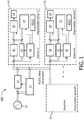
- a network 100 of dependable lamps 10 will work in a conventional mode in the presence of AC power supplied by AC mains 11.
- the dependable lamps 10 operate as conventional individual lamps.
- the dependable lamps 10 are in a battery charge or trickle charge mode.
- a control switch (not shown) may be used to switch the dependable lamp ON or OFF.
- the presence of the AC power i.e., grid/ main power
- the power monitoring unit 12 sends a signal to power isolator switch 13 to disconnect local distribution from the AC mains 11.
- all the dependable lamps 10 in the network 100 switch to form DC network for DATA/power transfer.
- the power monitoring unit 12 sends another signal to all the dependable lamps 10 to switch to the AC power.
- the network 100 is disconnected from the AC mains 11 through the power isolator switch 13 and each of the dependable lamps 10 is be powered by a charge management/battery unit 14. It is noted that the charge management/battery unit 14 may be two separate components.
- a user can trigger the particular lamp via a remote device or press switch or touch sensor (not shown).
- the network 100 may also include a proximity sensor 20 and/or a daylight sensor 21 to optimize the power resource to extend the light availability.
- the sensors 20/21 may also be included as part of a lighting driver 18. According, instead or in addition to the trigger from the user, the dependable lamp 10 can automatically sense the user and turn on and, if needed, obtain additional power as described below.
- the particular lamp 10 will search for power availability on the network 100 by sending a power dry up signal to one or more of the other dependable lamps 10 in the network 100. This is done by a communication controller 15.
- PLC power line communication or power line carrier (PLC), also known as power line digital subscriber line (PDSL), mains communication, power line telecom (PLT), power line networking (PLN), or broadband over power lines (BPL) and are systems for carrying data on a conductor also used for electric power transmission.
- PLC stands for power line communication or power line carrier (PLC), also known as power line digital subscriber line (PDSL), mains communication, power line telecom (PLT), power line networking (PLN), or broadband over power lines (BPL) and are systems for carrying data on a conductor also used for electric power transmission.
- PLC stands for power line communication or power line carrier (PLC), also known as power line digital subscriber line (PDSL), mains communication, power line telecom (PLT), power line networking (PLN), or broadband over power lines (BPL) and are systems for carrying data on a conductor also used for electric power transmission.
- the dependable lamps 10 that receive the power dry up signal and which have enough stored power in their own batteries 14 will send back a signal to the dependable lamp 10 which originated the power dry up signal request.
- Each of the dependable lamps 10 has a unique identifiable code that can be addressed. Once protocol hand shaking between the two or more dependable lamps 10 is complete the dependable lamp 10 which has stored energy will allow the access to its battery 14 to the dependable lamp 10 which originated the power dry up signal request.
- bypass switches 17 remain connected for a predetermined time or may be controlled by the dependable lamp 10 which originated the dry up signal request (i.e., the sender lamp 10).
- the communication controller 15 of the sender lamp 10 Before connecting power to the lighting driver 18 of a lighting unit 19, the communication controller 15 of the sender lamp 10 will ensure that light is not being generated the lighting unit 19.
- the lighting unit 19 may be a LED unit or other lighting producing unit.
- the communication controller 15 will also control the charge management/battery unit 14 so as not to charge the sender lamp 10's battery 14 and to use the power received only to power the lighting unit 19 via the lighting driver 18.
- the other dependable lamps 10 in the network 100 will be either isolated or in high impedance mode. In this manner, the network 100 functions in a seamless manner to make the light available to the user for a predetermined time.
- the network 100 will monitor and reconnect the dependable lamps 10 in the network 100 to the AC mains 11.
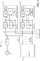
- Fig. 2 shows another embodiment of a power sharing network 200 for plug-in emergency lamps.
- the same reference numbers are used for elements that are the same or similar to those shown in Fig. 1 .
- separate wiring is used to share battery power between the dependable lamps 10 as well as from a master storage unit 22.
- the separate wiring is also used to allow the dependable lamps 10 to communicate with each other.
- each of the dependable lamps works independently as a conventional lamp with AC grid power.
- the dependable lamps 10 can sense the presence of the user in the room and turned ON from the power associated with the battery 14.
- the charge management system 14 will search for power availability on the DC network by sending the power dry up signal to each of the other dependable lamps 10 in the network 200.
- This request and reply procedure is similar to the protocol described in regard to the embodiment shown in Fig. 1 .
- Serial switches in the charge management unit 14 in the dependable lamps 10 are used to form the low impedance network for power flow from one of dependable lamps 10 to another.
- the network 200 may also include the presence/daylight sensors 20/21 to optimize the power resource to extend the light availability.
- the networks 100 and/or 200 may include "snap shot” feature to memorize a state of the room at the instant of the AC power outage.
- the dependable lamps 10 will switch on only when the room was in an illuminated state before the AC power outage occurred. Otherwise the dependable lamp 10 will not turn on automatically in the event of the AC power outage if the room was in non-illuminated state.
- the daylight sensor 21 is used to sense the illumination condition of surroundings at the instant of the AC power outage. The daylight sensor 21 should be able to differentiate between day light and artificial light so that it should not switch on during day.
- the method can be embodied as an algorithm or computer readable code that is accessible or embedded in one of the components (e.g., the communication controller 15) of the dependable lamp 10.
- the component for example, can be a microcontroller, ASIC or ROM.
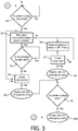
- step S1 of Fig. 3 it is determined if the AC power outage has occurred.
- step S2 it is checked if the room was illuminated at the time of the AC power outage.
- step S3 it is determined if the illumination was day light.
- step S4 it is checked if the room is currently occupied.
- step S5 the dependable lamp 10 is turned on.
- step S6 the dependable lamp 10 is maintained in the off state.
- step S7 it is checked if there is movement in the room.
- step S8 the dependable lamp is turned on.
- step S9 it is determined if the AC power has been restored.
- step S10 the dependable lamp 10 is turned off.
- the presence sensor 20 should be able to distinguish between the presence and the movement of the user so that whenever the presence senor 20 senses the movement in the room, the dependable lamp 10 is switched on even if the snap shot is dark at the time of the AC power outage.
- the presence sensor 20 takes control once the presence sensor 20 detects the movement in the room and switches off or on the dependable lamp 10 based on the movement detection.
- the dependable lamp 10 may also include an indicator to display various state conditions.
- the indicator can show the user that the dependable lamp 10 has sensed the dark condition at the time of the AC power outage and kept the lamp in off condition, e.g., the user may be asleep in the room.
- one node of the network 200 may be kept vacant intentionally. Whenever a charged battery is connected to the vacant node, the vacant node will communicate with the master storage unit 22 which will make the sharing power from the vacant node to the requester dependable lamp 10.
- the dependable lamps 10 may have variable light level outputs to reduce/extend the power backup time. Such dimming may be varied based on a predetermine time or a predetermined battery threshold level.
- a conventional on-off switch for controlling the dependable lamps 10 is replaced by a tactile switch 30.
- a tactile switch 30 Whenever a user presses the tactile switch 30, power to the dependable lamp 10 momentarily cuts OFF and such event is registered. Whenever the event gets registered; the dependable lamp 10 toggles from ON to OFF state or vice versa. This means if the dependable lamp 10 is ON condition it shifts to OFF condition or vice versa. If the dependable lamp 10 determines that a loss of grid power is beyond a predetermined threshold limit then the event is recognizes as a power outage condition and lighting battery backup function is initiated.
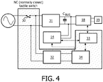
- Fig. 4 shows a schematic of the dependable lamp 10 including the tactile switch 30 (normally closed).
- the dependable lamp 10 includes two full bridge rectifiers (31 and 32), the lamp driver 18, the charge management unit 14, a lamp state monitoring unit 33 and a mains voltage monitoring unit 34.
- the output of the full bridge rectifier 32 is not filtered and is monitored by the mains monitoring unit 33 (e.g., via a voltage divider).
- the mains voltage monitoring unit 33 includes a mains voltage slope measurement subunit and an outage determination subunit (not separately shown in Fig. 4 ).
- These subunits can be either hardware components or ASIC (Application Specific Integrated Circuit) or embedded software or combinations thereof.
- ASIC Application Specific Integrated Circuit
- the various functional blocks communicate among themselves. It should also be understood that the functional blocks shown in Fig. 4 may be embedded in one controller or multiple controllers.
- the tactile switch 30 (e.g., normally closed (NC) single pole) is used to control the dependable lamp 10. Whenever the tactile switch 30 is pressed the mains supply is disrupted and this event is sensed by mains voltage monitoring unit 33 through the full bridge rectifier 32. This event is then recorded by the mains voltage monitoring unit 33. If the mains supply is not restored within predefined time (e.g., an internal timer triggered by the event reaches maximum set value, preferably in the range of 100milli seconds to 1 second, but other values may be used), the event is determined as a mains outage. If the dependable lamp 10 was in the ON condition previous to the occurrence of the event, a second timer may also triggered.
- predefined time e.g., an internal timer triggered by the event reaches maximum set value, preferably in the range of 100milli seconds to 1 second, but other values may be used
- power for the dependable lamp 10 is supplied from a (battery) backup for a predefined time until the second timer reach a predetermined set value (preferably in the range of 10 minutes to 60 minutes but other values can be used).
- the second timer may be used to control the amount of time the dependable lamp 10 is on the battery backup. If the lamp was in OFF position, the event can be ignored.
- the mains voltage monitoring unit 33 records this as a second event.
- the mains voltage monitoring unit 33 analyzes a slope of the mains voltage (the mains voltage waveform is typically monitored). Based upon the analysis, it can be determined that the second event is either a voltage dip or intended tactile switch operation. In the event of the intended tactile switch operation, the slope (dv/dt) of mains voltage is higher than during the voltage dip in the mains voltage. In the case of the voltage dip condition, the second event can be ignored. In the case of the intended tactile switch operation, the dependable lamp 10 state is changed (toggled) from ON to OFF or vice versa. This will help avoid false triggering of the dependable lamp 10.
- Fig. 5 shows an operational method for a dependable lamp with a tactile switch.
- the dependable lamp 10 is initially in STATE1 (i.e., the ON condition).
- the dependable lamp 10 maybe in either the ON or OFF state initially.
- the dependable lamp 10 checks for the availability of the mains/grids power. If the grid power is available, the dependable lamp 10 does not take any action to change state or condition. Otherwise, in step S22, the timer1 is initiated if the loss of grid power is detected. In step S23, it is checked if the mains voltage is restored within the predefined time.
- step S24 is determined if the event is an intended tactile switch operation or a voltage dip in the mains voltage.
- the dependable lamp 10 is switched (toggled) from STATE1 to STATE2 in this example and the timer 1 is reset.
- the time1 is reset (step S25) and it is checked if the dependable lamp 10 is already in the ON state (step S26). If the dependable lamp 10 is already in the ON state before the power outage then power (step 27) will be provided through a storage element (e.g., battery).
- the battery backup time is controlled by via timer2 (steps S28 and S29).
- the principles of the present invention are implemented as any combination of hardware, firmware and software.
- the software is preferably implemented as an application program tangibly embodied on a program storage unit or computer readable storage medium consisting of parts, or of certain devices and/or a combination of devices.
- the application program may be uploaded to, and executed by, a machine comprising any suitable architecture.
- the computer platform may also include an operating system and microinstruction code.
- the various processes and functions described herein may be either part of the microinstruction code or part of the application program, or any combination thereof, which may be executed by a CPU, whether or not such computer or processor is explicitly shown.
- various other peripheral units may be connected to the computer platform such as an additional data storage unit and a printing unit.
Claims (11)
- Réseau d'éclairage (100) comprenant une pluralité d'unités d'éclairage (10) et au moins un dispositif de commande (15), dans lequel chaque unité d'éclairage comprend :une unité d'émission d'éclairage (19) ;un driver (18) couplé à l'unité d'émission d'éclairage (19) ;un convertisseur CA/CC (16) agencé pour fournir de l'alimentation au driver (18) ;une unité de batterie CC (14), couplée au driver (18),dans lequel l'unité de batterie CC (14) est agencée pour fournir de l'alimentation au driver (18) si le convertisseur CA/CC ne peut pas fournir de l'alimentation au driver (18),caractérisé en ce que le dispositif de commande (15) est agencé pour redistribuer l'alimentation CC entre la pluralité d'unités d'éclairage (10) en permettant à l'alimentation provenant de l'unité de batterie CC (14) de passer de l'une de la pluralité d'unités d'éclairage (10) à une autre de la pluralité d'unités d'éclairage sur le réseau d'éclairage (100).
- Réseau d'éclairage (100) selon la revendication 1 comprenant en outre une unité de surveillance d'alimentation CA (12) agencée pour détecter la présence ou l'absence de l'alimentation CA.
- Réseau d'éclairage (100) selon la revendication 2, dans lequel le dispositif de commande redistribue l'alimentation CC en utilisant un chemin de distribution identique à celui utilisé par l'alimentation CA.
- Réseau d'éclairage (100) selon la revendication 1, dans lequel le dispositif de commande identifie en outre une disponibilité de la puissance CC dans chacune dans la pluralité d'unités d'éclairage (10) et ajuste la redistribution de l'alimentation CC pour étendre une disponibilité de lumière dans au moins une de la pluralité d'unités d'éclairage (10).
- Réseau d'éclairage (100) selon la revendication 1, dans lequel chacune de la pluralité d'unités d'éclairage (10) inclut un commutateur de dérivation pour commuter vers l'alimentation CC lorsque l'alimentation CA n'est pas disponible.
- Réseau d'éclairage (100) selon la revendication 1, dans lequel une ou plusieurs de la pluralité d'unités d'éclairage (10) inclut un capteur (20) agencé pour détecter une présence d'un utilisateur.
- Réseau d'éclairage (100) selon la revendication 1, dans lequel une ou plusieurs de la pluralité d'unités d'éclairage (10) inclut un capteur (21) agencé pour détecter la lumière du jour.
- Réseau d'éclairage (200) selon la revendication 2 comprenant en outre un dispositif de commande maître (22) agencé pour former un chemin de distribution d'alimentation CC.
- Réseau d'éclairage (200) selon la revendication 8, dans lequel le dispositif de commande maître (22) identifie en outre une disponibilité de la puissance CC dans chacune de la pluralité d'unités d'éclairage (10) et ajuste la redistribution de l'alimentation CC pour étendre une disponibilité de lumière dans au moins une de la pluralité d'unités d'éclairage (10).
- Réseau d'éclairage (200) selon la revendication 8, dans lequel une ou plusieurs de la pluralité d'unités d'éclairage (10) inclut un capteur (20) agencé pour détecter une présence d'un utilisateur.
- Réseau d'éclairage (200) selon la revendication 8, dans lequel une ou plusieurs de la pluralité d'unités d'éclairage (10) inclut un capteur (21) agencé pour détecter la lumière du jour.
Applications Claiming Priority (3)
| Application Number | Priority Date | Filing Date | Title |
|---|---|---|---|
| US201261656674P | 2012-06-07 | 2012-06-07 | |
| EP13732251.7A EP2859645B1 (fr) | 2012-06-07 | 2013-05-14 | Système et procédé d'éclairage de secours |
| PCT/IB2013/053924 WO2013182927A2 (fr) | 2012-06-07 | 2013-05-14 | Système et procédé d'éclairage de secours |
Related Parent Applications (2)
| Application Number | Title | Priority Date | Filing Date |
|---|---|---|---|
| EP13732251.7A Division EP2859645B1 (fr) | 2012-06-07 | 2013-05-14 | Système et procédé d'éclairage de secours |
| EP13732251.7A Division-Into EP2859645B1 (fr) | 2012-06-07 | 2013-05-14 | Système et procédé d'éclairage de secours |
Publications (2)
| Publication Number | Publication Date |
|---|---|
| EP3252919A1 EP3252919A1 (fr) | 2017-12-06 |
| EP3252919B1 true EP3252919B1 (fr) | 2020-11-04 |
Family
ID=48700656
Family Applications (2)
| Application Number | Title | Priority Date | Filing Date |
|---|---|---|---|
| EP17176584.5A Active EP3252919B1 (fr) | 2012-06-07 | 2013-05-14 | Système et procédé d'éclairage de secours |
| EP13732251.7A Active EP2859645B1 (fr) | 2012-06-07 | 2013-05-14 | Système et procédé d'éclairage de secours |
Family Applications After (1)
| Application Number | Title | Priority Date | Filing Date |
|---|---|---|---|
| EP13732251.7A Active EP2859645B1 (fr) | 2012-06-07 | 2013-05-14 | Système et procédé d'éclairage de secours |
Country Status (7)
| Country | Link |
|---|---|
| US (2) | US10547205B2 (fr) |
| EP (2) | EP3252919B1 (fr) |
| JP (2) | JP6133412B2 (fr) |
| CN (2) | CN107834689B (fr) |
| ES (1) | ES2655283T3 (fr) |
| RU (1) | RU2630476C2 (fr) |
| WO (1) | WO2013182927A2 (fr) |
Families Citing this family (16)
| Publication number | Priority date | Publication date | Assignee | Title |
|---|---|---|---|---|
| CN105408833B (zh) | 2013-03-13 | 2019-05-14 | 飞利浦灯具控股公司 | 用于能量削减的系统和方法 |
| WO2016097929A1 (fr) * | 2014-12-17 | 2016-06-23 | Philips Lighting Holding B.V. | Procédés, systèmes et appareil pour éclairage d'urgence |
| AU2016229833B2 (en) * | 2015-03-09 | 2019-11-28 | Zodiac Pool Systems, Inc. | Automatic auxiliary-power detector for pool systems |
| CN114786289A (zh) * | 2015-04-17 | 2022-07-22 | 豪倍照明公司 | 应急发光单元及其控制方法 |
| JP6575225B2 (ja) * | 2015-08-21 | 2019-09-18 | 東芝ライテック株式会社 | 照明システム |
| EP3166194A1 (fr) | 2015-11-05 | 2017-05-10 | Philips Lighting Holding B.V. | Circuit de commande, dispositif de commande et procédé de commande, approprié pour une alimentation secteur |
| US10187957B2 (en) | 2016-12-26 | 2019-01-22 | Arseniy E. Olevskiy | Multiway switch |
| WO2018189030A1 (fr) | 2017-04-11 | 2018-10-18 | Philips Lighting Holding B.V. | Système d'éclairage ayant des unités d'éclairage à stockage d'énergie local |
| US11139677B1 (en) * | 2017-04-13 | 2021-10-05 | Zio Holdings, Llc | Emergency lighting system and related devices and methods |
| CA3060082C (fr) | 2017-05-26 | 2022-04-12 | GE Lighting Solutions, LLC | Lampe de secours a batterie a del |
| JP6758530B2 (ja) | 2017-07-28 | 2020-09-23 | シグニファイ ホールディング ビー ヴィSignify Holding B.V. | Ac電力及びdc電力用の電力分配システム |
| US11239666B2 (en) | 2017-08-14 | 2022-02-01 | Signify Holding B.V. | Energy-storage integrated application device and operation thereof |
| JP7036985B2 (ja) * | 2018-09-03 | 2022-03-15 | シグニファイ ホールディング ビー ヴィ | 従前の電力サイクル持続時間に応じた光源の作動 |
| WO2020069513A2 (fr) * | 2018-09-30 | 2020-04-02 | David Heilman | Dispositif d'éclairage de dianostic |
| WO2021038114A1 (fr) * | 2019-08-30 | 2021-03-04 | Carlos Alejandro Llamas Linares | Dispositif d'éclairage d'urgence à technologie del ou similaire, base pour l'éclairage commun |
| WO2023131482A1 (fr) * | 2022-01-07 | 2023-07-13 | Signify Holding B.V. | Dispositif de commande de partage de puissance entre au moins deux dispositifs d'éclairage et procédé associé |
Family Cites Families (78)
| Publication number | Priority date | Publication date | Assignee | Title |
|---|---|---|---|---|
| SU1010696A1 (ru) * | 1980-10-08 | 1983-04-07 | Алтайский политехнический институт им.И.И.Ползунова | Устройство дл автоматического ввода резервного источника переменного напр жени |
| US5148158A (en) * | 1988-03-24 | 1992-09-15 | Teledyne Industries, Inc. | Emergency lighting unit having remote test capability |
| US6933627B2 (en) * | 1991-01-08 | 2005-08-23 | Nextek Power Systems Inc. | High efficiency lighting system |
| US5208584A (en) * | 1991-09-03 | 1993-05-04 | Jonathan Kaye | Traffic light and back-up traffic controller |
| CN2133088Y (zh) * | 1992-04-09 | 1993-05-12 | 复旦大学科学技术开发总公司 | 双光源自动切换应急照明灯 |
| US5574423A (en) * | 1995-03-10 | 1996-11-12 | Hubbell Incorporated | Self-diagnostic circuit for emergency lamphead |
| US20020074559A1 (en) * | 1997-08-26 | 2002-06-20 | Dowling Kevin J. | Ultraviolet light emitting diode systems and methods |
| US7482764B2 (en) * | 1997-08-26 | 2009-01-27 | Philips Solid-State Lighting Solutions, Inc. | Light sources for illumination of liquids |
| US5917250A (en) * | 1997-10-07 | 1999-06-29 | Lucent Technologies Inc. | Isolation circuit and verification controller for a power supply and power plant employing the same |
| DE19832550B4 (de) * | 1998-07-21 | 2004-06-03 | Jens Wich | Leuchte für Notstrombeleuchtungssystem und Verfahren zur Programmierung der Leuchte |
| US6369524B2 (en) * | 1999-02-26 | 2002-04-09 | Maf Technologies Corp. | Addressable light dimmer and addressing system |
| US6628083B2 (en) | 2000-04-28 | 2003-09-30 | Pickering Associates, Inc. | Central battery emergency lighting system |
| JP2002171205A (ja) * | 2000-11-30 | 2002-06-14 | Matsushita Electric Works Ltd | 電力線搬送用端末のシステム設定方法及び電力線搬送用端末設定装置 |
| US6510995B2 (en) * | 2001-03-16 | 2003-01-28 | Koninklijke Philips Electronics N.V. | RGB LED based light driver using microprocessor controlled AC distributed power system |
| JP2003068484A (ja) | 2001-06-14 | 2003-03-07 | Denso Corp | 放電灯装置およびそれを用いた投影装置 |
| JP2003068482A (ja) | 2001-08-28 | 2003-03-07 | Matsushita Electric Works Ltd | 照明装置 |
| US6653813B2 (en) | 2002-03-21 | 2003-11-25 | Thomson Licensing, S.A. | Apparatus and method for the power management of operatively connected modular devices |
| FI114194B (fi) * | 2002-10-08 | 2004-08-31 | Teknoware Oy | Valaisimien ryhmävalvonta |
| US6867558B2 (en) * | 2003-05-12 | 2005-03-15 | General Electric Company | Method and apparatus for networked lighting system control |
| US7307542B1 (en) * | 2003-09-03 | 2007-12-11 | Vantage Controls, Inc. | System and method for commissioning addressable lighting systems |
| DE10344619B4 (de) | 2003-09-25 | 2018-07-12 | Zumtobel Lighting Gmbh | Steuersystem für mehrere verteilt angeordnete Lampenbetriebsgeräte sowie Verfahren zum Initialisieren eines derartigen Steuersystems |
| KR101182674B1 (ko) * | 2004-03-15 | 2012-09-14 | 필립스 솔리드-스테이트 라이팅 솔루션스, 인크. | 전력 제어 방법 및 장치 |
| JP2005348592A (ja) * | 2004-06-07 | 2005-12-15 | Koito Mfg Co Ltd | 電源装置および車両用灯具 |
| US7026768B1 (en) * | 2004-08-04 | 2006-04-11 | Ruiz Carmelo C | Apparatus flashing lights in sequences indicating directions of movement in response to detected fire conditions and in response to an electrical power failure |
| WO2006032883A1 (fr) * | 2004-09-21 | 2006-03-30 | Saf-T-Glo Limited | Systeme d'eclairage d'urgence d'aeronef |
| JP4293367B2 (ja) | 2004-12-13 | 2009-07-08 | 株式会社竹中工務店 | 自律分散制御型蓄電システム |
| GB2422496B (en) | 2005-01-19 | 2008-03-26 | Cooper Lighting And Security L | Emergency lighting conversion module power pack |
| US7378805B2 (en) * | 2005-03-22 | 2008-05-27 | Fairchild Semiconductor Corporation | Single-stage digital power converter for driving LEDs |
| AU2007211026B2 (en) * | 2006-01-30 | 2013-07-11 | Energizer Brands, Llc | Battery powered lighting appliance |
| US9074736B2 (en) * | 2006-03-28 | 2015-07-07 | Wireless Environment, Llc | Power outage detector and transmitter |
| US8491159B2 (en) * | 2006-03-28 | 2013-07-23 | Wireless Environment, Llc | Wireless emergency lighting system |
| US7508162B2 (en) | 2006-04-07 | 2009-03-24 | Nokia Corporation | Method and apparatus for providing electrical energy to a portable device from energy storage of another portable device |
| JP5199555B2 (ja) * | 2006-08-02 | 2013-05-15 | パナソニック株式会社 | 配電システム |
| TWI311630B (en) * | 2006-10-26 | 2009-07-01 | Ind Tech Res Inst | Method for detecting surge of compressor |
| WO2008124701A2 (fr) | 2007-04-06 | 2008-10-16 | Sunovia Energe Technologies, Inc. | Unité lumineuse équipée d'un moyen de détection de pannes d'alimentation interne |
| US8035320B2 (en) * | 2007-04-20 | 2011-10-11 | Sibert W Olin | Illumination control network |
| US8312347B2 (en) * | 2007-05-04 | 2012-11-13 | Leviton Manufacturing Co., Inc. | Lighting control protocol |
| US20080303661A1 (en) * | 2007-06-06 | 2008-12-11 | Chick James S | Compact and self-contained security system |
| JP5144160B2 (ja) * | 2007-07-26 | 2013-02-13 | パナソニック株式会社 | 車載用負荷制御装置、車載用前照灯装置、および車載用尾灯装置 |
| US8587217B2 (en) * | 2007-08-24 | 2013-11-19 | Cirrus Logic, Inc. | Multi-LED control |
| US8092035B2 (en) * | 2008-09-10 | 2012-01-10 | Man-D-Tec | Illumination method and assembly |
| WO2010043923A1 (fr) * | 2008-10-17 | 2010-04-22 | Osram Gesellschaft mit beschränkter Haftung | Circuit d'alimentation électrique d'urgence pour ballasts électroniques à gradation d'intensité lumineuse et procédé correspondant |
| CN201294658Y (zh) * | 2008-11-14 | 2009-08-19 | 天津市联大通讯发展有限公司 | 无线遥控节能照明系统 |
| CN102265481A (zh) * | 2008-12-08 | 2011-11-30 | Tycka设计私人有限公司 | 一种改进的安全系统 |
| JP2010147010A (ja) * | 2008-12-22 | 2010-07-01 | Panasonic Electric Works Co Ltd | 照明装置およびそれを用いた照明器具 |
| RU2566736C2 (ru) * | 2009-02-26 | 2015-10-27 | Конинклейке Филипс Электроникс Н.В. | Резонансный преобразователь |
| GB2468652B (en) * | 2009-03-16 | 2011-08-31 | Ge Aviat Systems Ltd | Electrical power distribution |
| US20100290207A1 (en) * | 2009-05-14 | 2010-11-18 | Jing Yuan Technology Co., Ltd. | Emergency LED light device |
| TWI392192B (zh) * | 2009-06-03 | 2013-04-01 | Ge Investment Co Ltd | 配電系統 |
| JP5667187B2 (ja) * | 2009-08-05 | 2015-02-12 | コーニンクレッカ フィリップス エヌ ヴェ | 光誘導システム及びその制御方法 |
| US20110033649A1 (en) * | 2009-08-07 | 2011-02-10 | Brockway Ii Richard T | Package for Two-Way Mailing |
| US20120299480A1 (en) * | 2009-11-06 | 2012-11-29 | Neofocal Systems, Inc. | System And Method For Current Modulated Data Transmission |
| US8716953B2 (en) * | 2009-12-07 | 2014-05-06 | At&T Intellectual Property I, L.P. | Mechanisms for light management |
| US20120195032A1 (en) * | 2009-12-31 | 2012-08-02 | Shew Larry N | Modular lighting assembly |
| GB2476671B (en) * | 2010-01-04 | 2014-11-26 | Plastic Logic Ltd | Touch-sensing systems |
| CN101776240B (zh) * | 2010-01-11 | 2012-06-27 | 梅志国 | 一种应急照明系统及方法 |
| JPWO2011086806A1 (ja) | 2010-01-18 | 2013-05-16 | ローム株式会社 | 電力システム |
| KR101101473B1 (ko) * | 2010-04-22 | 2012-01-03 | 삼성전기주식회사 | 발광 다이오드 구동용 다중 전원 공급 장치 |
| US8274227B2 (en) * | 2010-05-06 | 2012-09-25 | Nextek Power Systems, Inc. | High-efficiency DC ballast arrangement with automatic polarity protection and emergency back-up for lighting fixture in a suspended DC-powered ceiling system |
| US8710995B2 (en) * | 2010-05-20 | 2014-04-29 | Rohm Co., Ltd. | Lighting apparatus |
| US9642227B2 (en) * | 2010-06-18 | 2017-05-02 | Thomas & Betts International Llc | Extending service life of lighting fixtures |
| US8410630B2 (en) * | 2010-07-16 | 2013-04-02 | Lumenpulse Lighting Inc. | Powerline communication control of light emitting diode (LED) lighting fixtures |
| US8657460B2 (en) * | 2010-07-22 | 2014-02-25 | Schneider Electric Industries Sas | Lamp with orientable lighting source |
| US8115397B2 (en) * | 2011-01-04 | 2012-02-14 | Greenwave Reality PTE, Ltd. | Power failure reporting in a networked light |
| AU2011100078B4 (en) * | 2011-01-18 | 2014-04-03 | Enlighten Australia Pty Ltd | Lighting system |
| CN104735872B (zh) * | 2011-01-28 | 2017-05-31 | 首尔半导体株式会社 | Led驱动电路封装 |
| JP5679197B2 (ja) * | 2011-02-22 | 2015-03-04 | 野口 宏和 | 蛍光灯型led照明装置 |
| CN102163873B (zh) | 2011-04-26 | 2014-05-07 | 广东康菱动力科技有限公司 | 精密制造业备用电力系统及其供电方法 |
| US8686662B1 (en) * | 2011-05-13 | 2014-04-01 | Cooper Technologies Company | Timed supercapacitor charge-up and emergency illumination |
| CN102263303B (zh) * | 2011-06-02 | 2016-09-14 | 福州天和新能电子科技有限公司 | 模块化锂动力电池及其管理系统和管理方法 |
| US9609720B2 (en) * | 2011-07-26 | 2017-03-28 | Hunter Industries, Inc. | Systems and methods for providing power and data to lighting devices |
| US8823272B2 (en) * | 2011-12-12 | 2014-09-02 | Cree, Inc. | Emergency lighting systems including bidirectional booster/charger circuits |
| US9253845B2 (en) * | 2011-12-15 | 2016-02-02 | Terralux, Inc. | Systems and methods for data communication from an LED device to the driver system |
| US20130169165A1 (en) * | 2011-12-15 | 2013-07-04 | Laurence P. Sadwick | Multi-Phase Lighting Driver |
| JP5919905B2 (ja) * | 2012-03-13 | 2016-05-18 | カシオ計算機株式会社 | 駆動装置、発光装置及び投影装置 |
| US8629618B1 (en) * | 2012-08-28 | 2014-01-14 | Christopher Tanner | Backup lighting apparatus |
| TWM461737U (zh) * | 2013-05-24 | 2013-09-11 | Hark Group Holding Corp | 照明裝置 |
| EP3138181B1 (fr) * | 2015-03-18 | 2022-03-23 | ABL IP Holding LLC | Système d'éclairage d'urgence à alimentation électrique par câble ethernet |
-
2013
- 2013-05-14 CN CN201711328574.1A patent/CN107834689B/zh active Active
- 2013-05-14 US US14/405,590 patent/US10547205B2/en active Active
- 2013-05-14 ES ES13732251.7T patent/ES2655283T3/es active Active
- 2013-05-14 RU RU2014152987A patent/RU2630476C2/ru active
- 2013-05-14 CN CN201380029701.1A patent/CN104335448B/zh active Active
- 2013-05-14 WO PCT/IB2013/053924 patent/WO2013182927A2/fr active Application Filing
- 2013-05-14 EP EP17176584.5A patent/EP3252919B1/fr active Active
- 2013-05-14 JP JP2015515604A patent/JP6133412B2/ja active Active
- 2013-05-14 EP EP13732251.7A patent/EP2859645B1/fr active Active
-
2017
- 2017-04-19 JP JP2017082504A patent/JP6400773B2/ja active Active
-
2019
- 2019-12-16 US US16/715,603 patent/US11031809B2/en active Active
Non-Patent Citations (1)
| Title |
|---|
| None * |
Also Published As
| Publication number | Publication date |
|---|---|
| RU2630476C2 (ru) | 2017-09-11 |
| RU2014152987A (ru) | 2016-08-10 |
| US20200119583A1 (en) | 2020-04-16 |
| CN104335448B (zh) | 2018-01-16 |
| JP6400773B2 (ja) | 2018-10-03 |
| JP6133412B2 (ja) | 2017-05-24 |
| ES2655283T3 (es) | 2018-02-19 |
| US10547205B2 (en) | 2020-01-28 |
| CN107834689B (zh) | 2021-09-14 |
| JP2015522918A (ja) | 2015-08-06 |
| US20150130282A1 (en) | 2015-05-14 |
| WO2013182927A2 (fr) | 2013-12-12 |
| CN107834689A (zh) | 2018-03-23 |
| EP3252919A1 (fr) | 2017-12-06 |
| CN104335448A (zh) | 2015-02-04 |
| EP2859645A2 (fr) | 2015-04-15 |
| US11031809B2 (en) | 2021-06-08 |
| JP2017152398A (ja) | 2017-08-31 |
| WO2013182927A3 (fr) | 2014-04-10 |
| EP2859645B1 (fr) | 2017-11-08 |
Similar Documents
| Publication | Publication Date | Title |
|---|---|---|
| US11031809B2 (en) | System and method for emergency lighting | |
| US20080218148A1 (en) | Intelligent Power Control | |
| US9431855B1 (en) | Timed charge-up and illumination | |
| JP5027642B2 (ja) | 照明制御システム | |
| KR20120036934A (ko) | 전력 모니터링 시스템 | |
| WO2018036845A1 (fr) | Dispositif d'éclairage destiné à fonctionner à partir d'une alimentation électrique principale et d'une alimentation électrique auxiliaire | |
| CN104302052A (zh) | 一种家庭灯光控制面板 | |
| CN108539834B (zh) | 单火线开关的充电控制电路、方法及智能家居系统 | |
| CN108365481A (zh) | 一种多功能智能插线板及其控制方法 | |
| KR200405775Y1 (ko) | 상용전원과 안전전압에서 이용 가능한 가로등 제어장치 | |
| CN101548584A (zh) | 用于控制设备操作的方法和电路 | |
| KR100887795B1 (ko) | 원격 감시 제어 시스템 및 인터페이스 장치 | |
| KR100789487B1 (ko) | 직류 전원 버스를 이용한 네트워크 시스템과 자동 전원제어방법 | |
| CN204104195U (zh) | 一种家庭灯光控制面板 | |
| KR200427664Y1 (ko) | 안전전압에서 동작하는 가로등 제어기 | |
| CN104521098B (zh) | 具有省电功能性的dc配电系统 | |
| JP2010015355A (ja) | 節電システム | |
| KR20070023506A (ko) | 상용전원과 안전전압에서 이용 가능한 가로등 제어장치 | |
| CN115151006B (zh) | 防爆电器柜、防爆照明系统及方法 | |
| JP4981650B2 (ja) | 配電システム | |
| JPWO2009054023A1 (ja) | 効果的電源消費制限装置 | |
| JP3768063B2 (ja) | 生活活動監視システム | |
| KR20220142826A (ko) | 신재생에너지 또는 계통전력을 전력원으로 하는 ess가 구비된 가정용 예비전력 절체 관리 시스템 | |
| KR101697143B1 (ko) | 축전형 전원이상 알림모듈 및 이를 이용한 비상전력 제어 방법 및 시스템 | |
| KR101693989B1 (ko) | 전등 사용 정보를 이용한 돌봄 시스템 |
Legal Events
| Date | Code | Title | Description |
|---|---|---|---|
| PUAI | Public reference made under article 153(3) epc to a published international application that has entered the european phase |
Free format text: ORIGINAL CODE: 0009012 |
|
| STAA | Information on the status of an ep patent application or granted ep patent |
Free format text: STATUS: THE APPLICATION HAS BEEN PUBLISHED |
|
| AC | Divisional application: reference to earlier application |
Ref document number: 2859645 Country of ref document: EP Kind code of ref document: P |
|
| AK | Designated contracting states |
Kind code of ref document: A1 Designated state(s): AL AT BE BG CH CY CZ DE DK EE ES FI FR GB GR HR HU IE IS IT LI LT LU LV MC MK MT NL NO PL PT RO RS SE SI SK SM TR |
|
| STAA | Information on the status of an ep patent application or granted ep patent |
Free format text: STATUS: REQUEST FOR EXAMINATION WAS MADE |
|
| 17P | Request for examination filed |
Effective date: 20180606 |
|
| RBV | Designated contracting states (corrected) |
Designated state(s): AL AT BE BG CH CY CZ DE DK EE ES FI FR GB GR HR HU IE IS IT LI LT LU LV MC MK MT NL NO PL PT RO RS SE SI SK SM TR |
|
| RAP1 | Party data changed (applicant data changed or rights of an application transferred) |
Owner name: PHILIPS LIGHTING HOLDING B.V. |
|
| RAP1 | Party data changed (applicant data changed or rights of an application transferred) |
Owner name: SIGNIFY HOLDING B.V. |
|
| RIC1 | Information provided on ipc code assigned before grant |
Ipc: H05B 47/185 20200101ALI20200131BHEP Ipc: H02J 9/02 20060101AFI20200131BHEP Ipc: H02J 9/06 20060101ALI20200131BHEP |
|
| GRAP | Despatch of communication of intention to grant a patent |
Free format text: ORIGINAL CODE: EPIDOSNIGR1 |
|
| STAA | Information on the status of an ep patent application or granted ep patent |
Free format text: STATUS: GRANT OF PATENT IS INTENDED |
|
| INTG | Intention to grant announced |
Effective date: 20200529 |
|
| GRAS | Grant fee paid |
Free format text: ORIGINAL CODE: EPIDOSNIGR3 |
|
| GRAA | (expected) grant |
Free format text: ORIGINAL CODE: 0009210 |
|
| STAA | Information on the status of an ep patent application or granted ep patent |
Free format text: STATUS: THE PATENT HAS BEEN GRANTED |
|
| AC | Divisional application: reference to earlier application |
Ref document number: 2859645 Country of ref document: EP Kind code of ref document: P |
|
| AK | Designated contracting states |
Kind code of ref document: B1 Designated state(s): AL AT BE BG CH CY CZ DE DK EE ES FI FR GB GR HR HU IE IS IT LI LT LU LV MC MK MT NL NO PL PT RO RS SE SI SK SM TR |
|
| REG | Reference to a national code |
Ref country code: GB Ref legal event code: FG4D |
|
| REG | Reference to a national code |
Ref country code: CH Ref legal event code: EP |
|
| REG | Reference to a national code |
Ref country code: AT Ref legal event code: REF Ref document number: 1332088 Country of ref document: AT Kind code of ref document: T Effective date: 20201115 |
|
| REG | Reference to a national code |
Ref country code: IE Ref legal event code: FG4D |
|
| REG | Reference to a national code |
Ref country code: DE Ref legal event code: R096 Ref document number: 602013073899 Country of ref document: DE |
|
| REG | Reference to a national code |
Ref country code: NL Ref legal event code: FP |
|
| REG | Reference to a national code |
Ref country code: AT Ref legal event code: MK05 Ref document number: 1332088 Country of ref document: AT Kind code of ref document: T Effective date: 20201104 |
|
| PG25 | Lapsed in a contracting state [announced via postgrant information from national office to epo] |
Ref country code: FI Free format text: LAPSE BECAUSE OF FAILURE TO SUBMIT A TRANSLATION OF THE DESCRIPTION OR TO PAY THE FEE WITHIN THE PRESCRIBED TIME-LIMIT Effective date: 20201104 Ref country code: GR Free format text: LAPSE BECAUSE OF FAILURE TO SUBMIT A TRANSLATION OF THE DESCRIPTION OR TO PAY THE FEE WITHIN THE PRESCRIBED TIME-LIMIT Effective date: 20210205 Ref country code: PT Free format text: LAPSE BECAUSE OF FAILURE TO SUBMIT A TRANSLATION OF THE DESCRIPTION OR TO PAY THE FEE WITHIN THE PRESCRIBED TIME-LIMIT Effective date: 20210304 Ref country code: RS Free format text: LAPSE BECAUSE OF FAILURE TO SUBMIT A TRANSLATION OF THE DESCRIPTION OR TO PAY THE FEE WITHIN THE PRESCRIBED TIME-LIMIT Effective date: 20201104 Ref country code: NO Free format text: LAPSE BECAUSE OF FAILURE TO SUBMIT A TRANSLATION OF THE DESCRIPTION OR TO PAY THE FEE WITHIN THE PRESCRIBED TIME-LIMIT Effective date: 20210204 |
|
| PG25 | Lapsed in a contracting state [announced via postgrant information from national office to epo] |
Ref country code: SE Free format text: LAPSE BECAUSE OF FAILURE TO SUBMIT A TRANSLATION OF THE DESCRIPTION OR TO PAY THE FEE WITHIN THE PRESCRIBED TIME-LIMIT Effective date: 20201104 Ref country code: BG Free format text: LAPSE BECAUSE OF FAILURE TO SUBMIT A TRANSLATION OF THE DESCRIPTION OR TO PAY THE FEE WITHIN THE PRESCRIBED TIME-LIMIT Effective date: 20210204 Ref country code: LV Free format text: LAPSE BECAUSE OF FAILURE TO SUBMIT A TRANSLATION OF THE DESCRIPTION OR TO PAY THE FEE WITHIN THE PRESCRIBED TIME-LIMIT Effective date: 20201104 Ref country code: IS Free format text: LAPSE BECAUSE OF FAILURE TO SUBMIT A TRANSLATION OF THE DESCRIPTION OR TO PAY THE FEE WITHIN THE PRESCRIBED TIME-LIMIT Effective date: 20210304 Ref country code: PL Free format text: LAPSE BECAUSE OF FAILURE TO SUBMIT A TRANSLATION OF THE DESCRIPTION OR TO PAY THE FEE WITHIN THE PRESCRIBED TIME-LIMIT Effective date: 20201104 Ref country code: AT Free format text: LAPSE BECAUSE OF FAILURE TO SUBMIT A TRANSLATION OF THE DESCRIPTION OR TO PAY THE FEE WITHIN THE PRESCRIBED TIME-LIMIT Effective date: 20201104 Ref country code: ES Free format text: LAPSE BECAUSE OF FAILURE TO SUBMIT A TRANSLATION OF THE DESCRIPTION OR TO PAY THE FEE WITHIN THE PRESCRIBED TIME-LIMIT Effective date: 20201104 |
|
| REG | Reference to a national code |
Ref country code: LT Ref legal event code: MG9D |
|
| PG25 | Lapsed in a contracting state [announced via postgrant information from national office to epo] |
Ref country code: HR Free format text: LAPSE BECAUSE OF FAILURE TO SUBMIT A TRANSLATION OF THE DESCRIPTION OR TO PAY THE FEE WITHIN THE PRESCRIBED TIME-LIMIT Effective date: 20201104 |
|
| PG25 | Lapsed in a contracting state [announced via postgrant information from national office to epo] |
Ref country code: SM Free format text: LAPSE BECAUSE OF FAILURE TO SUBMIT A TRANSLATION OF THE DESCRIPTION OR TO PAY THE FEE WITHIN THE PRESCRIBED TIME-LIMIT Effective date: 20201104 Ref country code: LT Free format text: LAPSE BECAUSE OF FAILURE TO SUBMIT A TRANSLATION OF THE DESCRIPTION OR TO PAY THE FEE WITHIN THE PRESCRIBED TIME-LIMIT Effective date: 20201104 Ref country code: CZ Free format text: LAPSE BECAUSE OF FAILURE TO SUBMIT A TRANSLATION OF THE DESCRIPTION OR TO PAY THE FEE WITHIN THE PRESCRIBED TIME-LIMIT Effective date: 20201104 Ref country code: EE Free format text: LAPSE BECAUSE OF FAILURE TO SUBMIT A TRANSLATION OF THE DESCRIPTION OR TO PAY THE FEE WITHIN THE PRESCRIBED TIME-LIMIT Effective date: 20201104 Ref country code: RO Free format text: LAPSE BECAUSE OF FAILURE TO SUBMIT A TRANSLATION OF THE DESCRIPTION OR TO PAY THE FEE WITHIN THE PRESCRIBED TIME-LIMIT Effective date: 20201104 Ref country code: SK Free format text: LAPSE BECAUSE OF FAILURE TO SUBMIT A TRANSLATION OF THE DESCRIPTION OR TO PAY THE FEE WITHIN THE PRESCRIBED TIME-LIMIT Effective date: 20201104 |
|
| REG | Reference to a national code |
Ref country code: DE Ref legal event code: R097 Ref document number: 602013073899 Country of ref document: DE |
|
| PG25 | Lapsed in a contracting state [announced via postgrant information from national office to epo] |
Ref country code: DK Free format text: LAPSE BECAUSE OF FAILURE TO SUBMIT A TRANSLATION OF THE DESCRIPTION OR TO PAY THE FEE WITHIN THE PRESCRIBED TIME-LIMIT Effective date: 20201104 |
|
| PLBE | No opposition filed within time limit |
Free format text: ORIGINAL CODE: 0009261 |
|
| STAA | Information on the status of an ep patent application or granted ep patent |
Free format text: STATUS: NO OPPOSITION FILED WITHIN TIME LIMIT |
|
| 26N | No opposition filed |
Effective date: 20210805 |
|
| PG25 | Lapsed in a contracting state [announced via postgrant information from national office to epo] |
Ref country code: IT Free format text: LAPSE BECAUSE OF FAILURE TO SUBMIT A TRANSLATION OF THE DESCRIPTION OR TO PAY THE FEE WITHIN THE PRESCRIBED TIME-LIMIT Effective date: 20201104 Ref country code: AL Free format text: LAPSE BECAUSE OF FAILURE TO SUBMIT A TRANSLATION OF THE DESCRIPTION OR TO PAY THE FEE WITHIN THE PRESCRIBED TIME-LIMIT Effective date: 20201104 |
|
| PG25 | Lapsed in a contracting state [announced via postgrant information from national office to epo] |
Ref country code: SI Free format text: LAPSE BECAUSE OF FAILURE TO SUBMIT A TRANSLATION OF THE DESCRIPTION OR TO PAY THE FEE WITHIN THE PRESCRIBED TIME-LIMIT Effective date: 20201104 |
|
| REG | Reference to a national code |
Ref country code: CH Ref legal event code: PL |
|
| PG25 | Lapsed in a contracting state [announced via postgrant information from national office to epo] |
Ref country code: LU Free format text: LAPSE BECAUSE OF NON-PAYMENT OF DUE FEES Effective date: 20210514 Ref country code: MC Free format text: LAPSE BECAUSE OF FAILURE TO SUBMIT A TRANSLATION OF THE DESCRIPTION OR TO PAY THE FEE WITHIN THE PRESCRIBED TIME-LIMIT Effective date: 20201104 Ref country code: LI Free format text: LAPSE BECAUSE OF NON-PAYMENT OF DUE FEES Effective date: 20210531 Ref country code: CH Free format text: LAPSE BECAUSE OF NON-PAYMENT OF DUE FEES Effective date: 20210531 |
|
| REG | Reference to a national code |
Ref country code: BE Ref legal event code: MM Effective date: 20210531 |
|
| PG25 | Lapsed in a contracting state [announced via postgrant information from national office to epo] |
Ref country code: IE Free format text: LAPSE BECAUSE OF NON-PAYMENT OF DUE FEES Effective date: 20210514 |
|
| PG25 | Lapsed in a contracting state [announced via postgrant information from national office to epo] |
Ref country code: IS Free format text: LAPSE BECAUSE OF FAILURE TO SUBMIT A TRANSLATION OF THE DESCRIPTION OR TO PAY THE FEE WITHIN THE PRESCRIBED TIME-LIMIT Effective date: 20210304 |
|
| PG25 | Lapsed in a contracting state [announced via postgrant information from national office to epo] |
Ref country code: BE Free format text: LAPSE BECAUSE OF NON-PAYMENT OF DUE FEES Effective date: 20210531 |
|
| PG25 | Lapsed in a contracting state [announced via postgrant information from national office to epo] |
Ref country code: HU Free format text: LAPSE BECAUSE OF FAILURE TO SUBMIT A TRANSLATION OF THE DESCRIPTION OR TO PAY THE FEE WITHIN THE PRESCRIBED TIME-LIMIT; INVALID AB INITIO Effective date: 20130514 |
|
| P01 | Opt-out of the competence of the unified patent court (upc) registered |
Effective date: 20230421 |
|
| PG25 | Lapsed in a contracting state [announced via postgrant information from national office to epo] |
Ref country code: CY Free format text: LAPSE BECAUSE OF FAILURE TO SUBMIT A TRANSLATION OF THE DESCRIPTION OR TO PAY THE FEE WITHIN THE PRESCRIBED TIME-LIMIT Effective date: 20201104 |
|
| PGFP | Annual fee paid to national office [announced via postgrant information from national office to epo] |
Ref country code: NL Payment date: 20230525 Year of fee payment: 11 Ref country code: FR Payment date: 20230523 Year of fee payment: 11 |
|
| PGFP | Annual fee paid to national office [announced via postgrant information from national office to epo] |
Ref country code: GB Payment date: 20230523 Year of fee payment: 11 |
|
| PGFP | Annual fee paid to national office [announced via postgrant information from national office to epo] |
Ref country code: DE Payment date: 20230726 Year of fee payment: 11 |