EP3251921B1 - Trackless route train - Google Patents
Trackless route train Download PDFInfo
- Publication number
- EP3251921B1 EP3251921B1 EP16172789.6A EP16172789A EP3251921B1 EP 3251921 B1 EP3251921 B1 EP 3251921B1 EP 16172789 A EP16172789 A EP 16172789A EP 3251921 B1 EP3251921 B1 EP 3251921B1
- Authority
- EP
- European Patent Office
- Prior art keywords
- axis
- module
- railless
- tugger train
- train
- Prior art date
- Legal status (The legal status is an assumption and is not a legal conclusion. Google has not performed a legal analysis and makes no representation as to the accuracy of the status listed.)
- Active
Links
- 230000033001 locomotion Effects 0.000 claims description 33
- 238000004146 energy storage Methods 0.000 claims description 6
- 238000012545 processing Methods 0.000 claims description 3
- 235000004443 Ricinus communis Nutrition 0.000 claims 2
- 238000013461 design Methods 0.000 description 7
- 230000005540 biological transmission Effects 0.000 description 6
- 239000000725 suspension Substances 0.000 description 5
- 230000008878 coupling Effects 0.000 description 3
- 238000010168 coupling process Methods 0.000 description 3
- 238000005859 coupling reaction Methods 0.000 description 3
- 238000012423 maintenance Methods 0.000 description 3
- 230000003287 optical effect Effects 0.000 description 3
- 230000001133 acceleration Effects 0.000 description 2
- 230000001419 dependent effect Effects 0.000 description 2
- 238000011156 evaluation Methods 0.000 description 2
- 238000003860 storage Methods 0.000 description 2
- 238000011161 development Methods 0.000 description 1
- 230000018109 developmental process Effects 0.000 description 1
- 230000007257 malfunction Effects 0.000 description 1
- 238000004519 manufacturing process Methods 0.000 description 1
- 238000000034 method Methods 0.000 description 1
- 238000012544 monitoring process Methods 0.000 description 1
- 238000005457 optimization Methods 0.000 description 1
- 230000010355 oscillation Effects 0.000 description 1
- 230000003534 oscillatory effect Effects 0.000 description 1
- 230000001105 regulatory effect Effects 0.000 description 1
- 238000005096 rolling process Methods 0.000 description 1
- 238000004904 shortening Methods 0.000 description 1
- 230000008054 signal transmission Effects 0.000 description 1
- 239000002689 soil Substances 0.000 description 1
- 239000007787 solid Substances 0.000 description 1
- 238000013519 translation Methods 0.000 description 1
Images


Classifications
-
- B—PERFORMING OPERATIONS; TRANSPORTING
- B62—LAND VEHICLES FOR TRAVELLING OTHERWISE THAN ON RAILS
- B62D—MOTOR VEHICLES; TRAILERS
- B62D59/00—Trailers with driven ground wheels or the like
- B62D59/04—Trailers with driven ground wheels or the like driven from propulsion unit on trailer
-
- B—PERFORMING OPERATIONS; TRANSPORTING
- B60—VEHICLES IN GENERAL
- B60S—SERVICING, CLEANING, REPAIRING, SUPPORTING, LIFTING, OR MANOEUVRING OF VEHICLES, NOT OTHERWISE PROVIDED FOR
- B60S9/00—Ground-engaging vehicle fittings for supporting, lifting, or manoeuvring the vehicle, wholly or in part, e.g. built-in jacks
- B60S9/14—Ground-engaging vehicle fittings for supporting, lifting, or manoeuvring the vehicle, wholly or in part, e.g. built-in jacks for both lifting and manoeuvring
- B60S9/205—Power driven manoeuvring fittings, e.g. reciprocably driven steppers or rotatably driven cams
-
- B—PERFORMING OPERATIONS; TRANSPORTING
- B62—LAND VEHICLES FOR TRAVELLING OTHERWISE THAN ON RAILS
- B62D—MOTOR VEHICLES; TRAILERS
- B62D13/00—Steering specially adapted for trailers
-
- B—PERFORMING OPERATIONS; TRANSPORTING
- B62—LAND VEHICLES FOR TRAVELLING OTHERWISE THAN ON RAILS
- B62D—MOTOR VEHICLES; TRAILERS
- B62D13/00—Steering specially adapted for trailers
- B62D13/005—Steering specially adapted for trailers operated from tractor steering system
-
- B—PERFORMING OPERATIONS; TRANSPORTING
- B62—LAND VEHICLES FOR TRAVELLING OTHERWISE THAN ON RAILS
- B62D—MOTOR VEHICLES; TRAILERS
- B62D13/00—Steering specially adapted for trailers
- B62D13/04—Steering specially adapted for trailers for individually-pivoted wheels
-
- B—PERFORMING OPERATIONS; TRANSPORTING
- B62—LAND VEHICLES FOR TRAVELLING OTHERWISE THAN ON RAILS
- B62D—MOTOR VEHICLES; TRAILERS
- B62D53/00—Tractor-trailer combinations; Road trains
- B62D53/005—Combinations with at least three axles and comprising two or more articulated parts
-
- B—PERFORMING OPERATIONS; TRANSPORTING
- B62—LAND VEHICLES FOR TRAVELLING OTHERWISE THAN ON RAILS
- B62D—MOTOR VEHICLES; TRAILERS
- B62D6/00—Arrangements for automatically controlling steering depending on driving conditions sensed and responded to, e.g. control circuits
- B62D6/002—Arrangements for automatically controlling steering depending on driving conditions sensed and responded to, e.g. control circuits computing target steering angles for front or rear wheels
Definitions
- the present invention relates to a trackless tugger train which has a train module, at least one transport module and at least two axle modules.
- Trackless tugger trains can be used in particular as industrial trucks for in-house transport.
- a trackless tugger train is for example from the EP 2 944 549 A2 known.
- the tugger train described there has a plurality of transport modules arranged one behind the other, which are pulled by means of a train module. Between the train module and the first transport module in the direction of travel and between the subsequent transport modules, an axle module is arranged in each case.
- the axle modules each have a wheel axle, on each of which two wheels are arranged.
- two cantilevers each connected to a transport module or train module are arranged on the axle modules.
- cantilevers are connected approximately centrally along the longitudinal extent of the wheel axle with each other via a hinge, so that the cantilevers are rotatable relative to each other. Due to the relative rotatability of the cantilever arms to each other, the transport modules are pivoted relative to the wheel axis when cornering the tugger train, the wheels themselves remain in their position relative to the wheel axle.
- hinges transmit all forces acting on the transport modules during operation of the tug train, such as the weight of the load, the weight of the transport modules, the inertia forces during acceleration and deceleration and the centrifugal forces when cornering, from the transport modules to the wheel axle.
- the hinges between the cantilevers and the wheel axle must therefore be able to withstand very high loads and also have a high rigidity.
- the high rigidity is important so that no disturbing roll vibrations occur during the journey of the tugger train. If the connection between the transport modules and the wheel axle or the axle modules is not sufficiently rigid, unfavorable loading and ground conditions may cause the outer corners of a transport module to be placed on the floor.
- a sufficiently strong and rigid structural design and design of the hinges and the cantilevers is technically possible, but it is very expensive and therefore leads to high production costs.
- document DE1079469 A is regarded as the closest prior art and shows a wagon train consisting of tractor and at least one trailer, wherein the trailer wheels a known steering is provided by which the wheels are guided in curves in the track of the drive wheels of the tractor, wherein the traction wheels of the tractor and all trailer wheels are driven in a conventional manner per axle via a differential gear, wherein the differential gear is connected to each lying behind the drive unit of the tractor axle to an outgoing drive unit of the drive shaft via a simple branching gear.
- the DE 10 2014 100 865 A1 discloses a tugger with a chassis and a bring in operative connection with transport units transport device, the chassis has two spaced apart in the vehicle longitudinal direction axle frame.
- the transport device comprises a longitudinal member and two webs angled therefrom, which are designed to receive forces generated by the transport units and connect the axle frames with one another in a force-transmitting manner.
- the US 2015/0344086 A1 discloses a trolley comprising a parent carriage with a chassis and a daughter carriage.
- the daughter car is carried by a lifting mechanism of the mother car.
- each axle module has a rigidly formed axle body, on which a first receiving device in the form of a rigid receptacle of the train module or a transport module is formed and on which a second receiving device for articulated connection of a transport module is formed, wherein on the axle body at least two wheels are mounted such that the wheels are each rotatable about a vertically to the bottom plane of the axle body rotational axis, wherein at the axle modules at least one electronic steering control device is provided, by means of which the current state of motion of the axle module and therefrom adjusted by the steering drive steering angle of the wheels are determinable, and wherein the steering control device includes a control device with which a steering or more steering drives of the axle module is / are controlled so that adjust the previously determined steering angle.
- the cantilever of the train module can also be designed as a transport module.
- a Starrafter means here that the connection between the axle body and thus the first receiving device and the train module or transport module is rigid or fixed.
- the tensile module or a transport module can be connected via a detachable connection with the first receiving device, so that a replacement of the arranged on the first receiving device train module or transport module can be done quickly and easily.
- the detachable connection can be formed for example by means of a screw connection.
- a second receiving device is formed on the axle body.
- This second receiving device is designed such that, in contrast to the first receiving device, an articulated connection of a transport module to the axle body is made possible.
- An articulated connection means that the transport module connected to the second receiving device or via the second receiving device to the axle body can be pivoted or rotated relative to the axle body when the tugger train moves in a curved path.
- the second receiving device may be formed, for example in the form of a trailer hitch.
- the articulated connection can be formed by a provided on the second receiving device ball joint, via which the axle body can be connected to the transport module or a cantilever of the transport module.
- a pin coupling is provided.
- Such a pin coupling can allow small rotational movements about the two axes of rotation perpendicular to the bolt.
- at least two wheels are mounted on the axle body in such a way that the wheels are each rotatable about a rotation axis formed vertically to the longitudinal axis of the axle body.
- the wheels arranged on the axle body can be rotated or pivoted relative to the axle body in order to be able to set a steering angle.
- This makes it possible that the total length of the tugger train with unchanged dimensions of the wheels and the transport modules and a constant minimum curve radius of the tugger train can be reduced.
- This can be achieved by allowing the wheels on the inside of the curve to fit more space-saving in the spaces between the transport modules by their rotatability than is the case in embodiments in which the wheels are rotatably mounted on the axle and thus not rotated relative to the axle can be.
- the tuggerubber Due to the possible shortening of the length of the tugger train, it can be achieved that the tuggerubber only has to travel short distances to unload the load from a transport module at the destination of the respective load.
- the inventive design it is now no longer necessary to provide hinges and thus form a solid and rigid structural design and design of the joints. Because of the rigid connection of the transport module to each axis module, a particularly rigid connection between the transport modules and the Achsmodulen be achieved so that disturbing Wankschwingisme can be prevented when driving the tugger train and also a placement of the outer corners of the transport modules on the floor itself can be avoided in unfavorable loading and soil conditions.
- the axis of rotation of the wheel may be formed outside or within a wheel contact surface of the wheel.
- the wheel contact surface of the wheel is the surface with which the wheel on the floor or on the ground surface on which the wheel rolls, stands or drives. If the rotation axis is arranged outside this wheel contact surface, then the perpendicular of the wheel contact surface is at a distance from the axis of rotation, so that the wheel can be pivoted about the axis of rotation at a distance from the axis of rotation. If the axis of rotation is arranged outside the wheel contact surface, then the friction surface of the wheel can be reduced, whereby the wear of the wheel can be reduced. In addition, a lighter steering of the wheel can be achieved at standstill of the tugger train.
- the axis of rotation is arranged within a wheel contact surface of the wheel, then the vertical perpendicular of the wheel contact surface coincides with the axis of rotation, so that the axis of rotation lies within the wheel, whereby it passes through the wheel and the wheel contact surface. If the axis of rotation is arranged within the wheel contact surface of the wheel, then it can be achieved that additional rolling resistances when passing over obstacles hardly affect the steering of the wheel.
- the rotatable suspension of the wheels on the axle body may be formed, for example, in that the wheels are each arranged on a steering knuckle, which is mounted rotatably about the axis of rotation on the axle body.
- the wheels are preferably each rotationally fixed to the stub axles, whereas the stub axles are themselves rotatably mounted on the axle body.
- the axis of rotation extends through the axle body or the steering knuckles and is thus spaced from the wheels or the perpendicular of the wheel contact surface of the wheels, so that in this case the axis of rotation of the wheels is arranged outside of the respective Radaufstands constitutional.
- the knuckle mounted on an axle body can be driven individually by means of a steering drive or the knuckle mounted on an axle body can be coupled to one another via a connecting rod and be drivable together by means of a steering drive. If each steering knuckle is assigned its own steering drive, then the steering knuckles can be driven and controlled individually, so that a pivoting or rotating movement of the steering knuckles independently of one another and thus also a pivoting or rotational movement of the wheels of an axle module can take place independently of each other.
- the axle stubs which are arranged on an axle body, to be connected to one another via a connecting rod, for example a coupling rod.
- the connecting rod is driven and thereby placed in a movement which is transmitted from the connecting rod to the steering knuckle such that the steering knuckle perform a twisting or pivoting movement.
- the stub axle of an axle module and thus the wheels of an axle module are driven together by means of only one steering drive.
- the connecting rod can be driven, for example, by means of a cylinder, in particular a hydraulic cylinder, whereby the connecting rod can thereby be moved translationally, wherein this translational movement can be transmitted to a crank via a swivel joint, wherein the crank can be fixedly connected to a corresponding steering knuckle, so that the translational movement of the connecting rod can be transferred or converted into a rotational movement of the steering knuckles.
- the wheels are each arranged in a single-turn stool receptacle or in a caster-wheel receptacle which are rotatably mounted on the axle body.
- the axis of rotation for the steering movement of the wheel preferably passes through the center of the wheel contact surface, so that the axis of rotation is arranged here within the wheel contact surface of the wheel.
- the axis of rotation is slightly laterally offset relative to the wheel contact surface of the wheel.
- the mounted on an axle body Einzelelfilschemelagen or Bockrollenamarean can be driven individually by means of a steering drive or together by means of a steering drive.
- the steering drive both the steering knuckle and the individual turntable receptacles or Bockrollenarean may be electrically, hydraulically or pneumatically.
- the steering drive may comprise an electric motor, a hydraulic or pneumatic motor or an electromagnetic linear drive.
- the steering drive may have a power controller, which may be formed for example in the form of power electronics for an electric motor or an electromagnetic linear actuator or in the form of a valve for hydraulic or pneumatic motors.
- the steering drive may have a transmission for transmitting the power of the engine to the wheels or the stub axle or the Einzelelwindsche-melagen or the Bockrollenfactn.
- a corresponding transmission can serve to transmit the mechanical movement and force generated by a motor to the suspension and thus the wheels and to adapt in size and shape to their needs.
- the rotational movement of an electric motor by means of a spindle drive or rack and pinion gear is converted into a translational motion and thus into a linear movement and then transmitted via a crank operation of the wheel suspensions and converted back into rotational movements.
- Hydraulic cylinders can be used to generate a translation movement.
- Crank drives are particularly suitable for the generation of steering movements, when when the wheels of an axle module are driven together by means of only one steering drive.
- a separate steering drive is provided for each wheel of an axle module, it is advantageous for the Rotary movement of the motor directly by means of a gear or traction mechanism to the associated suspension and thus to transmit the wheels.
- the rotational movement of the electric motors with the aid of toothed belt drives can be transmitted from the motor shafts to the axes of rotation of the wheel suspensions and simultaneously reduced in size.
- a gear transmission can be used as an alternative to a toothed belt drive.
- At least one sensor is arranged on at least one of the axle modules, by means of which vehicle dynamic data of the tugger train can be continuously measured.
- At least one electronic steering control device is provided on the axle modules, by means of which the current state of motion of the axle modules and from this the steering angle of the wheels to be set by the steering drive can be determined.
- the electronic steering control device can use, for example, the vehicle-dynamic data continuously measured by a sensor.
- the steering control device moreover includes a control device with which one steering or several steering drives of the axle module is / are regulated such that the previously determined steering angles are established.
- a power supply may be arranged on at least one of the axle modules, in order for example to be able to provide energy for the operation of an electronic steering control device, a sensor and / or a motor of a steering drive.
- the power supply can be effected, for example, by arranging at least one connection device for the power supply that can be connected to the train module via an electrical line to at least one of the axle modules.
- the energy required can be provided by the train module in electrical, pneumatic or hydraulic form and transmitted via electrical lines, hoses or pipes to the corresponding connection device on the axle module.
- At least one energy storage device is provided on at least one of the axle modules.
- the energy storage device may be, for example, a battery, an accumulator and / or a gas pressure accumulator.
- the required energy from the rotational movement of the wheels can be provided for example by means of an electric generator or by means of a hydraulic or pneumatic pump and stored in the energy storage device.
- At least one of the axle modules may further comprise at least one lifting device for raising and lowering a transport module connected to the axle module.
- the lifting device By means of the lifting device, if necessary, the transport module arranged on an axle module can be raised or lowered together with its load, whereby loading and / or unloading of the transport modules can be facilitated.
- the lifting device is preferably arranged in the region of the first and / or the second receiving device.
- acoustic and / or optical signal transmitter may be arranged on at least one of the axle modules.
- the driver of the tugger train may be a malfunction or a failure, for example, of the steering drives and thus the steering of the entire tugger train are displayed. If a corresponding signal generator is arranged on each axle module of such a tugger train, the driver can quickly and easily recognize which steering drive is no longer fully functional on which axle module.
- At least one electronic display device can be arranged on at least one of the axle modules.
- this electronic display device for example in the form of a display, the driver of the tugger train or other people information can be displayed.
- instructions for loading and unloading the transport modules can be transmitted herewith.
- At least one input device can be arranged on at least one of the axle modules. Via the input device data, information, feedback, etc. can be entered by the driver or by another person to store this data or information and retrieve it at a later time as needed.
- Such an input device may be, for example, a keyboard, a touchscreen in combination with an electronic display device, a microphone for voice input and / or a camera for gesture recognition.
- an operating data processing unit can be arranged on at least one of the axis modules.
- Such an operating data processing unit may be designed to record, evaluate and / or store operating data.
- operating variables such as vehicle speed, steering angle, load mass, acceleration or impact, etc.
- sensors present for the steering drive or a traction drive device and with additional sensors can be measured continuously or at discrete times.
- the measured operating variables can be evaluated in an electronic evaluation unit, such as a micro-controller, and compressed to an information and metrics.
- the data determined therefrom can be locally stored in an electronic storage device and / or forwarded to a central evaluation and / or storage device.
- the data transmission can be wirelessly via wireless, for example via WLAN.
- the data transmission between the axis modules and between the train module and the axis modules can also take place via a data line.
- the determined operating data can be used, for example, for a condition-dependent maintenance and maintenance of the tugger train or for the optimization of the logistical processes.
- a braking device is arranged on at least one of the axle modules, each one being arranged arranged on the axle module wheel own braking device of the brake device can be assigned.
- a traction drive device preferably has a motor and a transmission which can adapt the mechanical power of the motor with respect to the rotational speed and the torque and transmit it to the wheels of the axle module.
- the engine may be an electric, a hydraulic or a pneumatic engine.
- each wheel of an axle module is assigned its own traction drive device.
- each traction drive device drives only one wheel at a time.
- wheel hub motors can be used for this purpose.
- only one traction drive device for the wheels arranged on the axle module per axle module is provided, the drive power of the motor of the traction drive device is divided between the wheels by means of a differential gear.
- a power supply of the traction drive device or the traction drive devices can be done centrally from the train module via power lines.
- each axle module is assigned its own energy storage device, which serves for the energy supply of the travel drive device.
- the travel drive device may be controllable and / or controllable, for example, by means of an electronic travel control device.
- the drive control devices of the individual axle modules can be coordinated by a higher-level drive control, which may be located, for example, on the train module. For this purpose, a data and / or signal transmission between the axis modules and the train module is required. Instead of the central coordination of the individual drive control devices, a decentralized and therefore local control of the drive units of the individual axle modules is also possible.
- the propulsion force to be generated by the respective traction drive device can be set as a function of the traction force introduced by the preceding transport module or traction module.
- the introduced tensile force can be measured continuously and with the help of the control in the driving control device and the traction drive device, the driving force can be adjusted so that the introduced tensile force is reduced by a certain factor or limited to a maximum value.
- Fig. 1 schematically shows a trackless tugger train 100 according to the invention.
- the trackless tugger train has a train module 10, a plurality of transport modules 11 arranged one behind the other and a plurality of axle modules 12, one axle module 12 being arranged between two transport modules 11 arranged one behind the other and between the train module 10 and the first transport module 11 in the direction of travel F. Furthermore, an axle module 12 is also arranged on the last transport module 11 in the direction of travel F as termination of the tugger train 100.
- Each axis module 12 has a rigidly formed axle body 13, which is designed in the form of a rod or a beam.
- a first receiving device 14 in the form of a star receiving the train module 10 or a transport module 11 is formed, said first receiving device 14 seen in the direction of travel F is arranged on a front longitudinal side 15 of the axle body 13.
- the tension module 10 or one of the transport modules 11 is arranged rotationally fixed, so that a relative movement in the Connection region between the axle body 13 and the tension module 10 and the transport module 11 is prevented.
- a second receiving device 16 is arranged on each axle body 13, on which an articulated connection of a transport module 11 is made possible.
- the second receiving device is designed in the form of a trailer hitch.
- the transport module 11 For the connection of a transport module 11 to the second receiving device 16, the transport module 11 is provided with a cantilever 17, which can be connected directly to the second receiving device articulated.
- the tension module 10 has a cantilever arm 18, wherein this cantilever arm 18 is fixed, in particular rotationally fixed, to the first receiving device 14. With the main body 20 of the tension module 10 of the cantilever 18, however, is hinged.
- Two wheels 19 are each mounted on the individual axle bodies 13 of the axle modules 12 in such a way that the wheels 19 are each rotatable about an axis of rotation D formed vertically to the longitudinal axis L of the axle body 13.
- the wheels 19 can thereby be pivoted relative to the axle body 13, as in FIG Fig. 1 is shown.
- axle modules 12 and the transport modules 11 may be configured differently.
- Fig. 2 shows a representation in which the transport modules 11 are formed as modules, which have a support surface 43, or which have a receiving portion 44, in which loads can be hung.
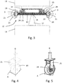
- Fig. 3 shows an embodiment of an axle module 12, in which the wheels 19 are each arranged in a single turntable receptacle 21, wherein both Einzelelwindschemelagen 21 are each rotatably mounted on the axle body 13. Due to the rotatable mounting, the wheels 19 can be rotated relative to the axle body 13.
- a pulley 22 is arranged on each of the individual turntable receptacles 21, wherein the pulleys 22 can each be driven via a motor 23, which is connected to the corresponding pulley 22 via a belt drive 24.
- a pulley 22, a motor 23 and a belt drive 24 together form a steering drive, wherein in the in Fig. 3 shown embodiment for each individual turntable receptacle 21 and thus for each wheel 19 a separate steering drive in the form of a pulley 22, a belt drive 24 and a motor 23 is provided.
- Fig. 4 is a corresponding single turnstile receptacle 21 with a wheel 19 disposed thereon shown in detail. It can be seen that the rotation axis D is arranged in this embodiment within the Radaufstands constitutional A and thus coincides with the vertical of the Radaufstands constitutional A.
- the wheels 19 at the in Fig. 3 shown embodiment in a as in Fig. 5 can be arranged 25 shown Bockrollenam. Also in this Bockrollenam 25, the axis of rotation D is disposed within the Radaufstands constitutional A, so that the axis of rotation D coincides with the vertical of the Radaufstands constitutional A.
- Fig. 6 shows a further embodiment of an axle module 12, wherein in this embodiment, the wheels 19 are each arranged on a steering knuckle 26 which is rotatably mounted on the axle body 13 about the rotation axis D.
- the rotation axis D of the wheel 19 is formed spaced from the respective wheel 19, so that the rotation axis D is arranged outside a wheel contact surface A of the wheel 19.
- the wheels 19 are rotatably mounted on the stub axles 26.
- the two stub axles 26 are coupled to one another via a connecting rod 27.
- This connecting rod of the steering drive is done by the connecting rod 27 is offset via a hydraulic cylinder 28 in a translational movement and this translational movement is converted or implemented to a rotational movement of the steering knuckle 26. This is especially in Fig. 7 shown schematically. Due to the rotational movement of the knuckle 26, a rotational movement of the wheels 19 takes place relative to the axle body 13.
- Fig. 8 shows a configuration of an axle module 12, in which sensors 29 are provided on the axle module 13.
- the sensors 29 shown here are designed as wheel speed sensors and positioned in the vicinity of the wheels 19.
- no hydraulic cylinder is provided for driving the connecting rod, but a motor 30, which sets the connecting rod 27 in a translational movement in order to achieve a steering of the wheels via the steering knuckle 26.
- a further sensor in the form of a position sensor can be arranged on the motor 30.
- each Wheel own drive device 38 is arranged, which is designed here in each case as a wheel hub motor with a gear.
- Fig. 9 shows an embodiment of an axle module 12, in which on the axle module 12, a connection device 30 for power supply, a lifting device 32, an optical and / or acoustic signal generator 33, an electronic display device 34 and an input device 35 are arranged.
- Fig. 10 shows an embodiment in which instead of the connection device for power supply, an energy storage device 36 is arranged.
- the lifting device 32 is shown in an extended position, in which the transport module 11 arranged on the second receiving device 16 provided in the region of the lifting device 32 is raised, not shown here.
- the lifting device 32 can be raised and lowered in order to achieve a movement of the attached to the second receiving device 16 transport module 11 upwards and downwards.
- the first receiving device 14 bores 37, via which a transport module 11 or a cantilever 18 of a tension module 10 can be releasably secured by screws.
- Fig. 12 shows a further embodiment of a single turntable receptacle 21, in which at the single turntable receptacle 21 directly a traction drive means 38 is arranged, which comprises a gear 39 and a motor 40.
- a brake device 41 is arranged on the single turntable receptacle 21, which has a wheel 19 directly associated braking device 42.
Description
Die vorliegende Erfindung betrifft einen gleislosen Routenzug, welcher ein Zugmodul, mindestens ein Transportmodul und mindestens zwei Achsmodule aufweist.The present invention relates to a trackless tugger train which has a train module, at least one transport module and at least two axle modules.
Gleislose Routenzüge können insbesondere als Flurförderzeuge für einen innerbetrieblichen Transport eingesetzt werden. Ein derartiger gleisloser Routenzug ist beispielsweise aus der
Diese Drehgelenke übertragen jedoch alle während des Betriebs des Routenzugs auf die Transportmodule wirkenden Kräfte, wie die Gewichtskraft der Last, das Eigengewicht der Transportmodule, die Massenträgheitskräfte beim Beschleunigen und Abbremsen sowie die Fliehkräfte bei Kurvenfahrten, von den Transportmodulen auf die Radachse. Die Drehgelenke zwischen den Kragarmen und der Radachse müssen daher sehr hohen Belastungen standhalten können und darüber hinaus eine hohe Steifigkeit aufweisen. Die hohe Steifigkeit ist wichtig, damit während der Fahrt des Routenzuges keine störenden Wankschwingungen entstehen. Bei einer nicht ausreichend steifen Verbindung zwischen den Transportmodulen und der Radachse bzw. den Achsmodulen kann es bei ungünstigen Beladungs- und Bodenverhältnissen zum Aufsetzen der äußeren Ecken eines Transportmoduls auf dem Boden kommen. Eine ausreichend feste und steife konstruktive Auslegung und Gestaltung der Drehgelenke und der Kragarme ist technisch zwar möglich, sie ist jedoch sehr aufwendig und führt daher zu hohen Herstellungskosten.However, these hinges transmit all forces acting on the transport modules during operation of the tug train, such as the weight of the load, the weight of the transport modules, the inertia forces during acceleration and deceleration and the centrifugal forces when cornering, from the transport modules to the wheel axle. The hinges between the cantilevers and the wheel axle must therefore be able to withstand very high loads and also have a high rigidity. The high rigidity is important so that no disturbing roll vibrations occur during the journey of the tugger train. If the connection between the transport modules and the wheel axle or the axle modules is not sufficiently rigid, unfavorable loading and ground conditions may cause the outer corners of a transport module to be placed on the floor. A sufficiently strong and rigid structural design and design of the hinges and the cantilevers is technically possible, but it is very expensive and therefore leads to high production costs.
Dokument
Die
Die
Es ist daher die Aufgabe der vorliegenden Erfindung, einen gleislosen Routenzug zur Verfügung zu stellen, welcher sich durch eine vereinfachte konstruktive Auslegung und Gestaltung auszeichnet bei gleichzeitigem Erreichen einer festen und ausreichend steifen Verbindung zwischen den Achsmodulen und den Transportmodulen.It is therefore the object of the present invention to provide a trackless tugger train, which is characterized by a simplified structural design and design while achieving a firm and sufficiently rigid connection between the axis modules and the transport modules.
Diese Aufgabe wird mit den Merkmalen des unabhängigen Anspruchs gelöst. Vorteilhafte Weiterbildungen der Erfindung sind in den abhängigen Ansprüchen angegeben.This object is achieved with the features of the independent claim. Advantageous developments of the invention are specified in the dependent claims.
Die Erfindung zeichnet sich dadurch aus, dass jedes Achsmodul einen starr ausgebildeten Achskörper aufweist, an welchem eine erste Aufnahmevorrichtung in Form einer Starraufnahme des Zugmoduls oder eines Transportmoduls ausgebildet ist und an welchem eine zweite Aufnahmevorrichtung zur gelenkigen Anbindung eines Transportmoduls ausgebildet ist, wobei an dem Achskörper mindestens zwei Räder derart gelagert sind, dass die Räder jeweils um eine vertikal zur Bodenebene des Achskörpers ausgebildete Drehachse drehbar sind, wobei an den Achsmodulen mindestens eine elektronische Lenksteuerungsvorrichtung vorgesehen ist, mittels welcher der aktuelle Bewegungszustand des Achsmoduls und hieraus die vom Lenkantrieb einzustellenden Lenkwinkel der Räder bestimmbar sind, und wobei die Lenksteuerungsvorrichtung eine Regelungsvorrichtung beinhaltet, mit der ein Lenk- oder mehrere Lenkantriebe des Achsmoduls so geregelt wird/werden, dass sich die zuvor bestimmten Lenkwinkel einstellen.The invention is characterized in that each axle module has a rigidly formed axle body, on which a first receiving device in the form of a rigid receptacle of the train module or a transport module is formed and on which a second receiving device for articulated connection of a transport module is formed, wherein on the axle body at least two wheels are mounted such that the wheels are each rotatable about a vertically to the bottom plane of the axle body rotational axis, wherein at the axle modules at least one electronic steering control device is provided, by means of which the current state of motion of the axle module and therefrom adjusted by the steering drive steering angle of the wheels are determinable, and wherein the steering control device includes a control device with which a steering or more steering drives of the axle module is / are controlled so that adjust the previously determined steering angle.
Erfindungsgemäß ist es nunmehr vorgesehen, dass an dem Achsmodul, insbesondere dem Achskörper des Achsmoduls, keine gelenkige Verbindung zwischen dem Zugmodul und dem in Fahrtrichtung ersten Transportmodul bzw. zwischen zwei hintereinander angeordneten Transportmodulen mehr vorgesehen ist. Damit sind auch nicht mehr beide an das Achsmodul bzw. den Achskörper des Achsmoduls angebundene Transportmodule relativ zu dem Achskörper drehbar bzw. verschwenkbar. Stattdessen ist es nunmehr vorgesehen, dass an dem Achskörper des Achsmoduls zwei Aufnahmevorrichtungen vorgesehen sind, wobei die erste dieser zwei Aufnahmevorrichtungen derart ausgebildet ist, dass das an dem Achskörper anzuordnende Transportmodul starr an dem Achskörper befestigt ist und damit eine verdrehfeste Verbindung zwischen dem Achskörper und dem Transportmodul ausgebildet ist. Diese erste Aufnahmevorrichtung ist vorzugsweise an der in Fahrtrichtung vorderen Längsseite des Achskörpers ausgebildet. Der Kragarm des Zugmoduls kann auch als Transportmodul ausgebildet sein. Eine Starraufnahme bedeutet hierbei, dass die Anbindung zwischen dem Achskörper und damit der ersten Aufnahmevorrichtung und dem Zugmodul bzw. Transportmodul starr bzw. fest ist. Das Zugmodul bzw. ein Transportmodul kann dabei über eine lösbare Verbindung mit der ersten Aufnahmevorrichtung verbunden sein, so dass ein Auswechseln des an der ersten Aufnahmevorrichtung angeordneten Zugmoduls bzw. Transportmoduls schnell und leicht erfolgen kann. Die lösbare Verbindung kann beispielsweise mittels einer Schraubverbindung ausgebildet sein. Die Anbindung des Zugmoduls an der ersten Aufnahmevorrichtung des in Fahrtrichtung ersten Achsmoduls erfolgt über einen Kragarm des Zugmoduls, so dass dieser Kragarm drehfest an dem Achskörper befestigt ist. Zusätzlich zu der ersten Aufnahmevorrichtung ist an dem Achskörper eine zweite Aufnahmevorrichtung ausgebildet. Diese zweite Aufnahmevorrichtung ist derart ausgebildet, dass im Gegensatz zu der ersten Aufnahmevorrichtung eine gelenkige Anbindung eines Transportmoduls an den Achskörper ermöglicht ist. Eine gelenkige Anbindung bedeutet, dass das an die zweite Aufnahmevorrichtung bzw. über die zweite Aufnahmevorrichtung an den Achskörper angebundene Transportmodul relativ zu dem Achskörper verschwenkt bzw. verdreht werden kann, wenn der Routenzug eine Kurvenbahn fährt. Die zweite Aufnahmevorrichtung kann beispielsweise in Form einer Anhängerkupplung ausgebildet sein. Die gelenkige Anbindung kann durch ein an der zweiten Aufnahmevorrichtung vorgesehenes Kugelgelenk ausgebildet sein, über welches der Achskörper mit dem Transportmodul bzw. einem Kragarm des Transportmoduls verbunden werden kann. Durch die gelenkige Anbindung können Relativverdrehungen zwischen dem Transportmodul und dem Achsmodul bzw. dem Achskörper des Achsmoduls um alle drei Raumachsen ermöglicht werden, wodurch erreicht werden kann, dass der Routenzug Bodenunebenheiten ausgleichen kann und über Fahrbahnen mit unterschiedlich geneigten Streckenabschnitten fahren kann. Alternativ zu der Ausbildung der gelenkigen Anbindung durch ein Kugelgelenk kann es auch vorgesehen sein, dass beispielsweise eine Bolzenkupplung vorgesehen ist. Eine derartige Bolzenkupplung kann kleine Drehbewegungen um die beiden zum Bolzen senkrecht stehenden Drehachsen ermöglichen. An dem Achskörper sind ferner mindestens zwei Räder derart gelagert, dass die Räder jeweils um eine vertikal zur Längsachse des Achskörpers ausgebildete Drehachse drehbar sind. Bei dem erfindungsgemäßen Routenzug ist es somit vorgesehen, dass die an dem Achskörper angeordneten Räder relativ zu dem Achskörper verdreht bzw. verschwenkt werden können, um einen Lenkwinkel einstellen zu können. Dadurch ist es möglich, dass die Gesamtlänge des Routenzuges bei unveränderten Abmessungen der Räder und der Transportmodule sowie einem gleich bleibenden minimalen Kurvenradius des Routenzuges verringert werden kann. Dies ist dadurch erreichbar, dass sich die Räder auf der Kurveninnenseite platzsparender in die Freiräume zwischen den Transportmodulen durch ihre Drehbarkeit einfügen können als dies bei Ausgestaltungen der Fall ist, bei welchen die Räder drehfest an dem Achskörper befestigt sind und damit nicht relativ zu dem Achskörper verdreht werden können. Durch die mögliche Verkürzung der Länge des Routenzuges kann erreicht werden, dass der Routenzugfahrer nur kurze Wege zum Entladen der Last von einem Transportmodul am Zielort der jeweiligen Last zurücklegen muss. Durch die erfindungsgemäße Ausgestaltung ist es nunmehr nicht mehr notwendig, Drehgelenke vorzusehen und damit eine feste und steife konstruktive Auslegung und Gestaltung der Drehgelenke auszubilden. Wegen der starren Anbindung des Transportmoduls an jeweils ein Achsmodul kann eine besonders steife Verbindung zwischen den Transportmodulen und den Achsmodulen erreicht werden, so dass störende Wankschwingungen bei der Fahrt des Routenzuges verhindert werden können und zudem auch ein Aufsetzen der äußeren Ecken der Transportmodule auf dem Boden selbst bei ungünstigen Beladungs- und Bodenverhältnissen vermieden werden kann.According to the invention, it is now provided that on the axle module, in particular the axle of the axle module, no articulated connection between the train module and the first transport module in the direction of travel or between two consecutively arranged transport modules is provided more. Thus, neither both the axle module or the axle body of the axle module connected transport modules are rotatable or pivotable relative to the axle body. Instead, it is now provided that two receiving devices are provided on the axle body of the axle module, wherein the first of these two receiving devices is designed such that the to be arranged on the axle beam transport module is rigidly attached to the axle and thus a rotationally fixed connection between the axle and the transport module is formed. This first receiving device is preferably formed on the front in the direction of travel longitudinal side of the axle body. The cantilever of the train module can also be designed as a transport module. A Starraufnahme means here that the connection between the axle body and thus the first receiving device and the train module or transport module is rigid or fixed. The tensile module or a transport module can be connected via a detachable connection with the first receiving device, so that a replacement of the arranged on the first receiving device train module or transport module can be done quickly and easily. The detachable connection can be formed for example by means of a screw connection. The connection of the train module to the first receiving device of the first axis module in the direction of travel via a cantilever arm of the train, so that this cantilever is rotatably mounted on the axle body. In addition to the first receiving device, a second receiving device is formed on the axle body. This second receiving device is designed such that, in contrast to the first receiving device, an articulated connection of a transport module to the axle body is made possible. An articulated connection means that the transport module connected to the second receiving device or via the second receiving device to the axle body can be pivoted or rotated relative to the axle body when the tugger train moves in a curved path. The second receiving device may be formed, for example in the form of a trailer hitch. The articulated connection can be formed by a provided on the second receiving device ball joint, via which the axle body can be connected to the transport module or a cantilever of the transport module. Due to the articulated connection relative rotations between the transport module and the axle module or the axle of the Axle module to all three spatial axes are made possible, which can be achieved so that the tugger train can compensate for bumps and drive on roads with differently inclined sections. As an alternative to the embodiment of the articulated connection by means of a ball joint, it can also be provided that, for example, a pin coupling is provided. Such a pin coupling can allow small rotational movements about the two axes of rotation perpendicular to the bolt. Furthermore, at least two wheels are mounted on the axle body in such a way that the wheels are each rotatable about a rotation axis formed vertically to the longitudinal axis of the axle body. In the tugger train according to the invention, it is thus provided that the wheels arranged on the axle body can be rotated or pivoted relative to the axle body in order to be able to set a steering angle. This makes it possible that the total length of the tugger train with unchanged dimensions of the wheels and the transport modules and a constant minimum curve radius of the tugger train can be reduced. This can be achieved by allowing the wheels on the inside of the curve to fit more space-saving in the spaces between the transport modules by their rotatability than is the case in embodiments in which the wheels are rotatably mounted on the axle and thus not rotated relative to the axle can be. Due to the possible shortening of the length of the tugger train, it can be achieved that the tuggerubber only has to travel short distances to unload the load from a transport module at the destination of the respective load. The inventive design, it is now no longer necessary to provide hinges and thus form a solid and rigid structural design and design of the joints. Because of the rigid connection of the transport module to each axis module, a particularly rigid connection between the transport modules and the Achsmodulen be achieved so that disturbing Wankschwingungen can be prevented when driving the tugger train and also a placement of the outer corners of the transport modules on the floor itself can be avoided in unfavorable loading and soil conditions.
Die Drehachse des Rades kann außerhalb oder innerhalb einer Radaufstandsfläche des Rades ausgebildet sein. Die Radaufstandsfläche des Rades ist die Fläche, mit welcher das Rad auf dem Fahrboden bzw. der Bodenfläche, auf welcher das Rad abrollt, steht bzw. fährt. Ist die Drehachse außerhalb dieser Radaufstandsfläche angeordnet, so ist die Lotrechte der Radaufstandsfläche beabstandet zu der Drehachse, so dass das Rad beabstandet zu der Drehachse um die Drehachse verschwenkbar ist. Ist die Drehachse außerhalb der Radaufstandsfläche angeordnet, so kann die Reibfläche des Rades reduziert werden, wodurch der Verschleiß des Rades reduziert werden. Zudem kann bei Stillstand des Routenzuges eine leichtere Lenkung des Rades erreicht werden. Ist die Drehachse innerhalb einer Radaufstandsfläche des Rades angeordnet, so fällt die Lotsenkrechte der Radaufstandsfläche zusammen mit der Drehachse, so dass die Drehachse innerhalb des Rades liegt, wodurch diese durch das Rad und die Radaufstandsfläche hindurchgeht. Ist die Drehachse innerhalb der Radaufstandsfläche des Rades angeordnet, so kann erreicht werden, dass zusätzliche Rollwiderstände beim Überfahren von Hindernissen sich kaum auf das Lenken des Rades auswirken.The axis of rotation of the wheel may be formed outside or within a wheel contact surface of the wheel. The wheel contact surface of the wheel is the surface with which the wheel on the floor or on the ground surface on which the wheel rolls, stands or drives. If the rotation axis is arranged outside this wheel contact surface, then the perpendicular of the wheel contact surface is at a distance from the axis of rotation, so that the wheel can be pivoted about the axis of rotation at a distance from the axis of rotation. If the axis of rotation is arranged outside the wheel contact surface, then the friction surface of the wheel can be reduced, whereby the wear of the wheel can be reduced. In addition, a lighter steering of the wheel can be achieved at standstill of the tugger train. If the axis of rotation is arranged within a wheel contact surface of the wheel, then the vertical perpendicular of the wheel contact surface coincides with the axis of rotation, so that the axis of rotation lies within the wheel, whereby it passes through the wheel and the wheel contact surface. If the axis of rotation is arranged within the wheel contact surface of the wheel, then it can be achieved that additional rolling resistances when passing over obstacles hardly affect the steering of the wheel.
Die drehbare Aufhängung der Räder an dem Achskörper kann beispielsweise dadurch ausgebildet sein, dass die Räder jeweils an einem Achsschenkel angeordnet sind, welcher um die Drehachse drehbar an dem Achskörper gelagert ist. Die Räder sind dabei vorzugsweise jeweils drehfest an den Achsschenkeln angeordnet, wohingegen die Achsschenkel selber drehbar an dem Achskörper gelagert sind. Die Drehachse verläuft dabei durch den Achskörper bzw. die Achsschenkel und ist dadurch beabstandet zu den Rädern bzw. der Lotrechten der Radaufstandsfläche der Räder, so dass hierbei die Drehachse der Räder außerhalb von der jeweiligen Radaufstandsfläche angeordnet ist.The rotatable suspension of the wheels on the axle body may be formed, for example, in that the wheels are each arranged on a steering knuckle, which is mounted rotatably about the axis of rotation on the axle body. The wheels are preferably each rotationally fixed to the stub axles, whereas the stub axles are themselves rotatably mounted on the axle body. The axis of rotation extends through the axle body or the steering knuckles and is thus spaced from the wheels or the perpendicular of the wheel contact surface of the wheels, so that in this case the axis of rotation of the wheels is arranged outside of the respective Radaufstandsfläche.
Die an einem Achskörper gelagerten Achsschenkel können einzeln mittels eines Lenkantriebs antreibbar sein oder die an einem Achskörper gelagerten Achsschenkel können über eine Verbindungsstange miteinander gekoppelt sein und gemeinsam mittels eines Lenkantriebs antreibbar sein. Ist jedem Achsschenkel ein eigener Lenkantrieb zugeordnet, so können die Achsschenkel einzeln angetrieben und angesteuert werden, so dass auch eine Verschwenk- bzw. Verdrehbewegung der Achsschenkel unabhängig voneinander und damit auch eine Verschwenk- bzw. Verdrehbewegung der Räder eines Achsmoduls unabhängig voneinander erfolgen kann. Alternativ ist es möglich, dass die an einem Achskörper angeordneten Achsschenkel über eine Verbindungsstange, beispielsweise einer Koppelstange, miteinander verbunden sind. Bei dieser Ausgestaltung wird die Verbindungsstange angetrieben und dadurch in eine Bewegung versetzt, welche von der Verbindungstange auf die Achsschenkel derart übertragen wird, dass die Achsschenkel eine Verdreh- bzw. Verschwenkbewegung ausführen. Bei dieser Ausgestaltung werden die Achsschenkel eines Achsmoduls und damit die Räder eines Achsmoduls gemeinsam mittels nur eines Lenkantriebs angetrieben. Die Verbindungsstange kann beispielsweise mittels eines Zylinders, insbesondere eines Hydraulikzylinders, angetrieben werden, wobei die Verbindungsstange dadurch translatorisch bewegt werden kann, wobei diese translatorische Bewegung an eine Kurbel über ein Drehgelenk übertragen werden kann, wobei die Kurbel mit einem entsprechenden Achsschenkel fest verbunden sein kann, so dass die translatorische Bewegung der Verbindungsstange in eine rotatorische Bewegung der Achsschenkel übertragen bzw. umgewandelt werden kann.The knuckle mounted on an axle body can be driven individually by means of a steering drive or the knuckle mounted on an axle body can be coupled to one another via a connecting rod and be drivable together by means of a steering drive. If each steering knuckle is assigned its own steering drive, then the steering knuckles can be driven and controlled individually, so that a pivoting or rotating movement of the steering knuckles independently of one another and thus also a pivoting or rotational movement of the wheels of an axle module can take place independently of each other. Alternatively, it is possible for the axle stubs, which are arranged on an axle body, to be connected to one another via a connecting rod, for example a coupling rod. In this embodiment, the connecting rod is driven and thereby placed in a movement which is transmitted from the connecting rod to the steering knuckle such that the steering knuckle perform a twisting or pivoting movement. In this embodiment, the stub axle of an axle module and thus the wheels of an axle module are driven together by means of only one steering drive. The connecting rod can be driven, for example, by means of a cylinder, in particular a hydraulic cylinder, whereby the connecting rod can thereby be moved translationally, wherein this translational movement can be transmitted to a crank via a swivel joint, wherein the crank can be fixedly connected to a corresponding steering knuckle, so that the translational movement of the connecting rod can be transferred or converted into a rotational movement of the steering knuckles.
Alternativ zu den Achsschenkeln kann es vorgesehen sein, dass die Räder jeweils in einer Einzeldrehschemelaufnahme oder in einer Bockrollenaufnahme angeordnet sind, welche an dem Achskörper drehbar gelagert sind. Bei einer derartigen Ausgestaltung verläuft die Drehachse für die Lenkbewegung des Rades vorzugsweise durch den Mittelpunkt der Radaufstandsfläche, so dass die Drehachse hier innerhalb der Radaufstandsfläche des Rades angeordnet ist. In Abhängigkeit der Ausgestaltung der jeweiligen Einzeldrehschemelaufnahmen oder der jeweiligen Bockrollenaufnahmen kann es jedoch auch vorgesehen sein, dass die Drehachse leicht seitlich versetzt zu der Radaufstandsfläche des Rades verläuft. Um eine Drehbewegung der Räder um ihre Drehachse und damit relativ zu dem Achskörper erreichen zu können, kann an den Einzeldrehschemelaufnahmen oder Bockrollenaufnahmen jeweils eine Riemenscheibe angeordnet sein, welche über einen Motor angetrieben werden kann, indem ein Zugmittel, beispielsweise ein Riementrieb, zwischen der Riemenscheibe und dem Motor gespannt ist.As an alternative to the stub axles, it may be provided that the wheels are each arranged in a single-turn stool receptacle or in a caster-wheel receptacle which are rotatably mounted on the axle body. In such an embodiment, the axis of rotation for the steering movement of the wheel preferably passes through the center of the wheel contact surface, so that the axis of rotation is arranged here within the wheel contact surface of the wheel. Depending on the configuration of the respective individual turntable receptacles or the respective caster wheel receivers, however, it may also be provided that the axis of rotation is slightly laterally offset relative to the wheel contact surface of the wheel. In order to achieve a rotational movement of the wheels about its axis of rotation and thus relative to the axle body, can on the A single turntable or Bockrollenaufnahmen each be arranged a pulley, which can be driven by a motor by a traction means, such as a belt drive, between the pulley and the engine is tensioned.
Die an einem Achskörper gelagerten Einzeldrehschemelaufnahmen oder Bockrollenaufnahmen können einzeln mittels eines Lenkantriebs oder gemeinsam mittels eines Lenkantriebs antreibbar sein.The mounted on an axle body Einzeleldrehschemelaufnahmen or Bockrollenaufnahmen can be driven individually by means of a steering drive or together by means of a steering drive.
Der Lenkantrieb sowohl der Achsschenkel als auch der Einzeldrehschemelaufnahmen oder Bockrollenaufnahmen kann elektrisch, hydraulisch oder pneumatisch ausgebildet sein. Beispielsweise kann der Lenkantrieb einen Elektromotor, einen hydraulischen oder pneumatischen Motor oder einen elektromagnetischen Linearantrieb aufweisen. Ferner kann der Lenkantrieb einen Leistungs-steller aufweisen, welcher beispielsweise in Form einer Leistungselektronik für einen Elektromotor oder einen elektromagnetischen Linearantrieb oder in Form eines Ventils für hydraulische oder pneumatische Motoren ausgebildet sein kann. Weiter kann der Lenkantrieb ein Getriebe zur Übertragung der Leistung des Motors auf die Räder bzw. die Achsschenkel oder die Einzeldrehsche-melaufnahmen oder die Bockrollenaufnahmen aufweisen. Ein entsprechendes Getriebe kann dazu dienen, die von einem Motor erzeugte mechanische Bewegung und Kraft an die Radaufhängung und damit die Räder zu übertragen und in Größe und Form an deren Bedürfnisse anzupassen. So kann es beispielsweise vorgesehen sein, dass die Drehbewegung eines Elektromotors mit Hilfe eines Spindeltriebes oder Zahnstangentriebes in eine Translationsbewegung und damit in eine lineare Bewegung umgewandelt wird und anschließend über einen Kurbelbetrieb an die Radaufhängungen übertragen und wieder in Drehbewegungen zurückgewandelt wird. Zur Erzeugung einer Translationsbewegung können hydraulische Zylinder verwendet werden. Kurbeltriebe eignen sich insbesondere für die Erzeugung der Lenkbewegungen, wenn wenn die Räder eines Achsmoduls gemeinsam mittels nur eines Lenkantriebs angetrieben werden. Ist für jedes Rad eines Achsmoduls ein eigener Lenkantrieb vorgesehen, so ist es vorteilhaft, die Drehbewegung des Motors direkt mit Hilfe eines Zahnrad- oder Zugmittelgetriebes auf die zugehörige Radaufhängung und damit die Räder zu übertragen. Beispielsweise kann die Drehbewegung der Elektromotoren mit Hilfe von Zahnriementrieben von den Motorwellen auf die Drehachsen der Radaufhängungen übertragen und dabei gleichzeitig untersetzt werden. Alternativ zu einem Zahnriementrieb kann beispielsweise auch ein Zahnradgetriebe verwendet werden.The steering drive both the steering knuckle and the individual turntable receptacles or Bockrollenaufnahmen may be electrically, hydraulically or pneumatically. For example, the steering drive may comprise an electric motor, a hydraulic or pneumatic motor or an electromagnetic linear drive. Further, the steering drive may have a power controller, which may be formed for example in the form of power electronics for an electric motor or an electromagnetic linear actuator or in the form of a valve for hydraulic or pneumatic motors. Further, the steering drive may have a transmission for transmitting the power of the engine to the wheels or the stub axle or the Einzeleldrehsche-melaufnahmen or the Bockrollenaufnahmen. A corresponding transmission can serve to transmit the mechanical movement and force generated by a motor to the suspension and thus the wheels and to adapt in size and shape to their needs. Thus, it may be provided, for example, that the rotational movement of an electric motor by means of a spindle drive or rack and pinion gear is converted into a translational motion and thus into a linear movement and then transmitted via a crank operation of the wheel suspensions and converted back into rotational movements. Hydraulic cylinders can be used to generate a translation movement. Crank drives are particularly suitable for the generation of steering movements, when when the wheels of an axle module are driven together by means of only one steering drive. If a separate steering drive is provided for each wheel of an axle module, it is advantageous for the Rotary movement of the motor directly by means of a gear or traction mechanism to the associated suspension and thus to transmit the wheels. For example, the rotational movement of the electric motors with the aid of toothed belt drives can be transmitted from the motor shafts to the axes of rotation of the wheel suspensions and simultaneously reduced in size. As an alternative to a toothed belt drive, for example, a gear transmission can be used.
Um den Fahrbetrieb des Routenzuges und damit die Bewegung des Routenzuges insbesondere bei Kurvenfahrten besonders gut steuern bzw. regeln zu können, ist es bevorzugt vorgesehen, dass an mindestens einem der Achsmodule mindestens ein Sensor angeordnet ist, mittels welchem fahrdynamische Daten des Routenzuges kontinuierlich messbar sind. Hierdurch ist eine kontinuierliche Überwachung und Steuerung des Routenzuges während des Fahrbetriebes des Routenzuges möglich, um beispielsweise sich aufbauende Wankschwingungen der einzelnen Transportmodule frühzeitig erkennen und unterbinden zu können.In order to be able to control or regulate the driving operation of the tugger train particularly well when cornering, it is preferably provided that at least one sensor is arranged on at least one of the axle modules, by means of which vehicle dynamic data of the tugger train can be continuously measured. As a result, a continuous monitoring and control of the tugger train during the driving operation of the tugger train is possible in order, for example, to be able to recognize and prevent, for example, oscillatory oscillations of the individual transport modules that build up at an early stage.
Ferner ist vorgesehen, dass an den Achsmodulen mindestens eine elektronische Lenksteuerungsvorrichtung vorgesehen ist, mittels welcher der aktuelle Bewegungszustand der Achsmodule und hieraus die vom Lenkantrieb einzustellender Lenkwinkel der Räder bestimmbar sind. Die elektronische Lenksteuerungsvorrichtung kann hierfür beispielsweise die von einem Sensor kontinuierlich gemessenen fahrdynamischen Daten verwenden. Die Lenksteuervorrichtung beinhaltet darüber hinaus eine Regelungsvorrichtung mit der ein Lenk- oder mehrere Lenkantriebe des Achsmoduls so geregelt wird/werden, dass sich die zuvor bestimmten Lenkwinkel einstellen.It is further provided that at least one electronic steering control device is provided on the axle modules, by means of which the current state of motion of the axle modules and from this the steering angle of the wheels to be set by the steering drive can be determined. For this purpose, the electronic steering control device can use, for example, the vehicle-dynamic data continuously measured by a sensor. The steering control device moreover includes a control device with which one steering or several steering drives of the axle module is / are regulated such that the previously determined steering angles are established.
Weiter kann es vorgesehen sein, dass an mindestens einem der Achsmodule eine Energieversorgung angeordnet ist, um beispielsweise Energie für den Betrieb einer elektronischen Lenksteuerungsvorrichtung, eines Sensors und/oder eines Motors eines Lenkantriebs zur Verfügung stellen zu können.Furthermore, provision may be made for a power supply to be arranged on at least one of the axle modules, in order for example to be able to provide energy for the operation of an electronic steering control device, a sensor and / or a motor of a steering drive.
Die Energieversorgung kann beispielsweise dadurch erfolgen, dass an mindestens einem der Achsmodule mindestens eine über eine elektrische Leitung mit dem Zugmodul verbindbare Anschlussvorrichtung zur Energieversorgung angeordnet ist. Die benötigte Energie kann dabei von dem Zugmodul in elektrischer, pneumatischer oder hydraulischer Form bereitgestellt werden und über elektrische Leitungen, Schläuche oder Rohre hin zu der entsprechenden Anschlussvorrichtung an dem Achsmodul übertragen werden.The power supply can be effected, for example, by arranging at least one connection device for the power supply that can be connected to the train module via an electrical line to at least one of the axle modules. The energy required can be provided by the train module in electrical, pneumatic or hydraulic form and transmitted via electrical lines, hoses or pipes to the corresponding connection device on the axle module.
Weiter kann es auch vorgesehen sein, dass an mindestens einem der Achsmodule mindestens eine Energiespeichervorrichtung vorgesehen ist. Die Energiespeichervorrichtung kann beispielsweise eine Batterie, ein Akkumulator und/oder ein Gasdruckspeicher sein. Bei einer derartigen Ausgestaltung kann die benötigte Energie aus der Drehbewegung der Räder zum Beispiel mittels eines elektrischen Generators oder mit Hilfe einer hydraulischen oder pneumatischen Pumpe bereitgestellt werden und in der Energiespeichervorrichtung gespeichert werden. Dadurch kann gewährleistet werden, dass auch bei einem stillstehenden Routenzug zumindest vorübergehend Energie an den einzelnen Achsmodulen zur Verfügung steht.Furthermore, it can also be provided that at least one energy storage device is provided on at least one of the axle modules. The energy storage device may be, for example, a battery, an accumulator and / or a gas pressure accumulator. In such an embodiment, the required energy from the rotational movement of the wheels can be provided for example by means of an electric generator or by means of a hydraulic or pneumatic pump and stored in the energy storage device. As a result, it is possible to ensure that energy is available at the individual axis modules at least temporarily even when the route is stationary.
An mindestens einem der Achsmodule kann weiter mindestens eine Hubvorrichtung zum Anheben und Senken eines mit dem Achsmodul verbundenen Transportmoduls angeordnet sein. Mittels der Hubvorrichtung kann bei Bedarf das an einem Achsmodul angeordnete Transportmodul zusammen mit seiner Ladung angehoben oder auch abgesenkt werden, wodurch ein Beladen und/oder Entladen der Transportmodule erleichtert werden kann. Die Hubvor-richtung ist vorzugsweise im Bereich der ersten und/oder der zweiten Aufnahmevorrichtung angeordnet.At least one of the axle modules may further comprise at least one lifting device for raising and lowering a transport module connected to the axle module. By means of the lifting device, if necessary, the transport module arranged on an axle module can be raised or lowered together with its load, whereby loading and / or unloading of the transport modules can be facilitated. The lifting device is preferably arranged in the region of the first and / or the second receiving device.
Weiter kann es vorgesehen sein, dass an mindestens einem der Achsmodule mindestens ein akustischer und/oder optischer Signalgeber angeordnet ist. Mittels eines akustischen und/oder optischen Signalgebers kann beispielsweise dem Fahrer des Routenzuges eine Fehlfunktion bzw. ein Ausfall zum Beispiel des bzw. der Lenkantriebe und damit der Lenkung des gesamten Routenzuges angezeigt werden. Ist an jedem Achsmodul eines derartigen Routenzuges ein entsprechender Signalgeber angeordnet, so kann der Fahrer schnell und auf einfache Art und Weise erkennen, welcher Lenkantrieb an welchem Achsmodul nicht mehr vollständig funktionsfähig ist.Furthermore, provision may be made for at least one acoustic and / or optical signal transmitter to be arranged on at least one of the axle modules. By means of an acoustic and / or optical signal generator, for example, the driver of the tugger train may be a malfunction or a failure, for example, of the steering drives and thus the steering of the entire tugger train are displayed. If a corresponding signal generator is arranged on each axle module of such a tugger train, the driver can quickly and easily recognize which steering drive is no longer fully functional on which axle module.
An mindestens einem der Achsmodule kann ferner mindestens eine elektronische Anzeigeeinrichtung angeordnet sein. Über diese elektronische Anzeigeeinrichtung, beispielsweise in Form eines Displays, können dem Fahrer des Routenzuges oder auch anderen Personen Informationen angezeigt werden. Insbesondere können hiermit Anweisungen zum Be- und Entladen der Transportmodule übermittelt werden. Es können aber beispielsweise auch Fehlermeldungen oder Hinweise zu erforderlichen Wartungs- und/oder Instandhaltungsmaßnahmen über die Anzeigeeinrichtung angezeigt werden.Furthermore, at least one electronic display device can be arranged on at least one of the axle modules. About this electronic display device, for example in the form of a display, the driver of the tugger train or other people information can be displayed. In particular, instructions for loading and unloading the transport modules can be transmitted herewith. However, it is also possible, for example, to display error messages or instructions for required maintenance and / or servicing measures via the display device.
Ferner kann an mindestens einem der Achsmodule mindestens eine Eingabevorrichtung angeordnet sein. Über die Eingabevorrichtung können Daten, Informationen, Rückmeldungen usw. durch den Fahrer oder durch eine andere Person eingegeben werden, um diese Daten bzw. Informationen zu speichern und zu einem späteren Zeitpunkt je nach Bedarf abrufen zu können. Eine derartige Eingabevorrichtung kann beispielsweise eine Tastatur, ein Touchscreen in Kombination mit einer elektronischen Anzeigeeinrichtung, ein Mikrofon für eine Spracheingabe und/oder eine Kamera zur Gestenerkennung sein.Furthermore, at least one input device can be arranged on at least one of the axle modules. Via the input device data, information, feedback, etc. can be entered by the driver or by another person to store this data or information and retrieve it at a later time as needed. Such an input device may be, for example, a keyboard, a touchscreen in combination with an electronic display device, a microphone for voice input and / or a camera for gesture recognition.
Weiter kann an mindestens einem der Achsmodule eine Betriebsdatenverarbeitungseinheit angeordnet sein. Eine derartige Betriebsdatenverarbeitungseinheit kann dazu ausgebildet sein, Betriebsdaten zu erfassen, auszuwerten und/oder zu speichern. Zur Erfassung der Betriebsdaten des Routenzuges können kontinuierlich oder zu diskreten Zeitpunkten Betriebsgrößen, wie beispielsweise die Fahrgeschwindigkeit, die Lenkwinkel, die Lastmasse, Beschleunigung bzw. Stöße usw., mit für den Lenkantrieb oder eine Fahrantriebsvorrichtung vorhandenen Sensoren sowie mit zusätzlichen Sensoren gemessen werden. Die gemessenen Betriebsgrößen können in einer elektronischen Auswertungseinheit, wie beispielsweise einem Mikro-Controller, ausgewertet und zu einer Information und zu Kennzahlen verdichtet werden. Die daraus ermittelten Daten können in einer elektronischen Speichervorrichtung lokal gespeichert und/oder zu einer zentralen Auswerte- und/oder Speicherungsvorrichtung weitergeleitet werden. Die Datenübertragung kann drahtlos per Funk zum Beispiel über WLAN erfolgen. Alternativ kann die Datenübertragung zwischen den Achsmodulen und zwischen dem Zugmodul und den Achsmodulen auch über eine Datenleitung erfolgen. Die ermittelten Betriebsdaten können zum Beispiel für eine zustandsabhängige Wartung und Instandhaltung des Routenzuges oder für die Optimierung der logistischen Prozesse verwendet werden.Furthermore, an operating data processing unit can be arranged on at least one of the axis modules. Such an operating data processing unit may be designed to record, evaluate and / or store operating data. To detect the operational data of the tugger train, operating variables such as vehicle speed, steering angle, load mass, acceleration or impact, etc., with sensors present for the steering drive or a traction drive device and with additional sensors can be measured continuously or at discrete times. The measured operating variables can be evaluated in an electronic evaluation unit, such as a micro-controller, and compressed to an information and metrics. The data determined therefrom can be locally stored in an electronic storage device and / or forwarded to a central evaluation and / or storage device. The data transmission can be wirelessly via wireless, for example via WLAN. Alternatively, the data transmission between the axis modules and between the train module and the axis modules can also take place via a data line. The determined operating data can be used, for example, for a condition-dependent maintenance and maintenance of the tugger train or for the optimization of the logistical processes.
Um den Aufbau des Routenzuges weiter vereinfachen zu können und um insbesondere verhindern zu können, dass die aufzubringenden Bremskräfte des Routenzuges nicht über eine Kette des Routenzugsystems geleitet werden muss, kann es vorgesehen sein, dass an mindestens einem der Achsmodule eine Bremsvorrichtung angeordnet ist, wobei jedem an dem Achsmodul angeordneten Rad eine eigene Bremseinrichtung der Bremsvorrichtung zugeordnet sein kann.In order to be able to further simplify the structure of the tugger train and in particular to be able to prevent the applied braking forces of the tugger train from being routed via a chain of the tugger train system, it may be provided that a braking device is arranged on at least one of the axle modules, each one being arranged arranged on the axle module wheel own braking device of the brake device can be assigned.
Um die von dem Zugmodul auf die einzelnen Transportmodule zu übertragende Zugkraft reduzieren zu können, kann es bevorzugt vorgesehen sein, dass mindestens eines der Achsmodule des Routenzuges eine Fahrantriebseinrichtung aufweist. Eine Fahrantriebseinrichtung weist vorzugsweise einen Motor und ein Getriebe auf, das die mechanische Leistung des Motors hinsichtlich der Drehzahl und des Momentes anpassen und an die Räder des Achsmoduls übertragen kann. Der Motor kann ein elektrischer, ein hydraulischer oder ein pneumatischer Motor sein.In order to be able to reduce the tractive force to be transmitted by the train module to the individual transport modules, it can preferably be provided that at least one of the axle modules of the tugger train has a travel drive device. A traction drive device preferably has a motor and a transmission which can adapt the mechanical power of the motor with respect to the rotational speed and the torque and transmit it to the wheels of the axle module. The engine may be an electric, a hydraulic or a pneumatic engine.
Bevorzugt ist es dabei vorgesehen, dass jedem Rad eines Achsmoduls eine eigene Fahrantriebseinrichtung zugeordnet ist. Bei einer derartigen Ausgestaltung treibt jede Fahrantriebseinrichtung jeweils nur ein Rad an. Hierfür können beispielsweise Radnabenmotoren eingesetzt sein. Ist hingegen pro Achsmodul nur eine Fahrantriebseinrichtung für die an dem Achsmodul angeordneten Räder vorgesehen, so wird die Antriebsleistung des Motors der Fahrantriebs-einrichtung auf die Räder durch ein Differentialgetriebe aufgeteilt.It is preferably provided that each wheel of an axle module is assigned its own traction drive device. In such an embodiment, each traction drive device drives only one wheel at a time. For example, wheel hub motors can be used for this purpose. Is on the other hand only one traction drive device for the wheels arranged on the axle module per axle module is provided, the drive power of the motor of the traction drive device is divided between the wheels by means of a differential gear.
Eine Energieversorgung der Fahrantriebseinrichtung bzw. der Fahrantriebseinrichtungen kann zentral von dem Zugmodul aus über Energieleitungen erfolgen. Alternativ kann es auch vorgesehen sein, dass jedem Achsmodul eine eigene Energiespeichervorrichtung zugeordnet ist, welche für die Energieversorgung der Fahrantriebseinrichtung dient.A power supply of the traction drive device or the traction drive devices can be done centrally from the train module via power lines. Alternatively, it may also be provided that each axle module is assigned its own energy storage device, which serves for the energy supply of the travel drive device.
Die Fahrantriebseinrichtung kann beispielsweise mittels einer elektronischen Fahrsteuerungsvorrichtung regelbar und/oder steuerbar sein. Die Fahrsteuerungsvorrichtungen der einzelnen Achsmodule können durch eine übergeordnete Fahrsteuerung, die sich beispielsweise an dem Zugmodul befinden kann, koordiniert werden. Hierzu ist eine Daten- und/oder Signalübertragung zwischen den Achsmodulen und dem Zugmodul erforderlich. Anstelle der zentralen Koordinierung der einzelnen Fahrsteuerungsvorrichtungen ist auch eine dezentrale und damit lokale Steuerung der Fahrantriebseinrichtungen der einzelnen Achsmodule möglich. Hierzu kann die von der jeweiligen Fahrantriebseinrichtung zu erzeugende Vortriebskraft in Abhängigkeit von der vom voranfahrenden Transportmodul bzw. Zugmodul eingeleiteten Zugkraft eingestellt werden. Die eingeleitete Zugkraft kann dabei laufend gemessen werden und mit Hilfe der Regelung in der Fahrsteuerungsvorrichtung und der Fahrantriebseinrichtung kann die Vortriebskraft so eingestellt werden, dass die eingeleitete Zugkraft um einen gewissen Faktor verringert wird bzw. auf einen Maximalwert begrenzt wird.The travel drive device may be controllable and / or controllable, for example, by means of an electronic travel control device. The drive control devices of the individual axle modules can be coordinated by a higher-level drive control, which may be located, for example, on the train module. For this purpose, a data and / or signal transmission between the axis modules and the train module is required. Instead of the central coordination of the individual drive control devices, a decentralized and therefore local control of the drive units of the individual axle modules is also possible. For this purpose, the propulsion force to be generated by the respective traction drive device can be set as a function of the traction force introduced by the preceding transport module or traction module. The introduced tensile force can be measured continuously and with the help of the control in the driving control device and the traction drive device, the driving force can be adjusted so that the introduced tensile force is reduced by a certain factor or limited to a maximum value.
Weitere, die Erfindung verbessernde Maßnahmen werden nachstehend gemeinsam mit der Beschreibung bevorzugter Ausführungsbeispiele der Erfindung anhand der Figuren näher dargestellt.Further, measures improving the invention will be described in more detail below together with the description of preferred embodiments of the invention with reference to FIGS.
Es zeigen:
- Fig. 1
- eine schematische Darstellung eines gleislosen Routenzuges gemäß der Erfindung,
- Fig. 2
- eine Darstellung einer Aneinanderreihung von Achsmodulen und Transportmodulen in verschiedenen Ausgestaltungen für einen wie in
Fig. 1 gezeigten gleislosen Routenzug, - Fig. 3
- eine schematische Darstellung eines Achsmoduls gemäß einer Ausgestaltung der Erfindung für einen wie
Fig. 1 gezeigten gleislosen Routenzug, - Fig. 4
- eine schematische Darstellung einer Einzeldrehschemelaufnahme mit einem daran angeordneten Rad gemäß der Erfindung,
- Fig. 5
- eine schematische Darstellung einer Bockrollenaufnahme mit einem daran angeordneten Rad gemäß der Erfindung,
- Fig. 6
- eine schematische Darstellung eines Achsmoduls gemäß einer weiteren Ausgestaltung der Erfindung für einen wie
Fig. 1 gezeigten gleislosen Routenzug, - Fig. 7
- eine weitere Darstellung des in
Fig. 6 gezeigten Achsmoduls während einer Lenkbewegung, - Fig. 8
- eine schematische Darstellung eines Achsmoduls gemäß einer weiteren Ausgestaltung der Erfindung für einen wie
Fig. 1 gezeigten gleislosen Routenzug, - Fig. 9
- eine schematische Darstellung eines Achsmoduls gemäß einer weiteren Ausgestaltung der Erfindung für einen wie
Fig. 1 gezeigten gleislosen Routenzug, - Fig. 10
- eine schematische Darstellung eines Achsmoduls gemäß einer weiteren Ausgestaltung der Erfindung für einen wie
Fig. 1 gezeigten gleislosen Routenzug, - Fig. 11
- eine schematische Darstellung eines Achsmoduls gemäß einer weiteren Ausgestaltung der Erfindung für einen wie
Fig. 1 gezeigten gleislosen Routenzug, und - Fig. 12
- eine schematische Darstellung einer Einzeldrehschemelaufnahme mit einer daran angeordneten Fahrantriebseinrichtung und einer daran angeordneten Bremsvorrichtung gemäß der Erfindung.
- Fig. 1
- a schematic representation of a trackless tugger train according to the invention,
- Fig. 2
- a representation of a juxtaposition of axle modules and transport modules in various configurations for a like in
Fig. 1 shown trackless tugger train, - Fig. 3
- a schematic representation of an axis module according to an embodiment of the invention for a like
Fig. 1 shown trackless tugger train, - Fig. 4
- a schematic representation of a single turntable receptacle with a wheel arranged thereon according to the invention,
- Fig. 5
- a schematic representation of a Bockrollenaufnahme with a wheel disposed thereon according to the invention,
- Fig. 6
- a schematic representation of an axis module according to another embodiment of the invention for a like
Fig. 1 shown trackless tugger train, - Fig. 7
- another illustration of the in
Fig. 6 shown axis module during a steering movement, - Fig. 8
- a schematic representation of an axis module according to another embodiment of the invention for a like
Fig. 1 shown trackless tugger train, - Fig. 9
- a schematic representation of an axis module according to another embodiment of the invention for a like
Fig. 1 shown trackless tugger train, - Fig. 10
- a schematic representation of an axis module according to another embodiment of the invention for a like
Fig. 1 shown trackless tugger train, - Fig. 11
- a schematic representation of an axis module according to another embodiment of the invention for a like
Fig. 1 shown trackless tugger train, and - Fig. 12
- a schematic representation of a single turntable receptacle with a drive device arranged thereon and a braking device arranged thereon according to the invention.
Jedes Achsmodul 12 weist einen starr ausgebildeten Achskörper 13 auf, welcher in Form einer Stange bzw. eines Balkens ausgebildet ist.Each
An jedem Achskörper 13 ist eine erste Aufnahmevorrichtung 14 in Form einer Starraufnahme des Zugmoduls 10 oder eines Transportmoduls 11 ausgebildet, wobei diese erste Aufnahmevorrichtung 14 in Fahrtrichtung F gesehen an einer vorderen Längsseite 15 des Achskörpers 13 angeordnet ist. An dieser ersten Aufnahmevorrichtung 14 ist das Zugmodul 10 bzw. eines der Transportmodule 11 verdrehfest angeordnet, so dass eine Relativbewegung in dem Anbindungsbereich zwischen dem Achskörper 13 und dem Zugmodul 10 bzw. dem Transportmodul 11 verhindert ist.At each
Zusätzlich zu der ersten Aufnahmevorrichtung 14 ist an jedem Achskörper 13 eine zweite Aufnahmevorrichtung 16 angeordnet, an welcher eine gelenkige Anbindung eines Transportmoduls 11 ermöglicht ist. Die zweite Aufnahmevorrichtung ist in Form einer Anhängerkupplung ausgebildet. Durch die gelenkige Anbindung eines Transportmoduls 11 an diese zweite Aufnahmevorrichtung 16 kann erreicht werden, dass das an der zweiten Aufnahmevorrichtung 16 angebundene Transportmodul 11 relativ zu dem Achskörper 13 verschwenkt werden kann, wenn der Routenzug 100 eine Kurvenbahn fährt.In addition to the
Für die Anbindung eines Transportmoduls 11 an die zweite Aufnahmevorrichtung 16 ist das Transportmodul 11 mit einem Kragarm 17 versehen, welcher unmittelbar an die zweite Aufnahmevorrichtung gelenkig angebunden werden kann.For the connection of a
Die Anbindung des Transportmoduls 11 an die erste Aufnahmevorrichtung 16 erfolgt hingegen ohne einen derartigen Kragarm.The connection of the
Zur Anbindung des Zugmoduls 10 an die erste Aufnahmevorrichtung 14 weist das Zugmodul 10 einen Kragarm 18 auf, wobei dieser Kragarm 18 fest, insbesondere drehfest, an der ersten Aufnahmevorrichtung 14 angebunden ist. Mit dem Hauptkörper 20 des Zugmoduls 10 ist der Kragarm 18 hingegen gelenkig verbunden.To connect the
An den einzelnen Achskörpern 13 der Achsmodule 12 sind jeweils zwei Räder 19 derart gelagert, dass die Räder 19 jeweils um eine vertikal zur Längsachse L des Achskörpers 13 ausgebildete Drehachse D drehbar sind. Bei einer Kurvenfahrt des Routenzuges 100 können dadurch die Räder 19 relativ zu dem Achskörper 13 verschwenkt werden, wie in
Wie in den nachfolgenden
An den Einzeldrehschemelaufnahmen 21 ist jeweils eine Riemenscheibe 22 angeordnet, wobei die Riemenscheiben 22 jeweils über einen Motor 23, welcher mit der entsprechenden Riemenscheibe 22 über einen Riementrieb 24 verbunden ist, angetrieben werden können. Eine Riemenscheibe 22, ein Motor 23 und ein Riementrieb 24 bilden zusammen einen Lenkantrieb aus, wobei bei der in
In
Alternativ zu einer Einzeldrehschemelaufnahme 21 können die Räder 19 bei der in
Die Räder 19 sind an den Achsschenkeln 26 drehfest gelagert. Die beiden Achsschenkel 26 sind über eine Verbindungsstange 27 miteinander gekoppelt. Über diese Verbindungsstange erfolgt der Lenkantrieb, indem die Verbindungsstange 27 über einen hydraulischen Zylinder 28 in eine translatorische Bewegung versetzt wird und diese translatorische Bewegung zu einer rotatorischen Bewegung der Achsschenkel 26 umgewandelt bzw. umgesetzt wird. Dies ist insbesondere in
Bei der in
Wie in den
Claims (19)
- Railless tugger train (100) with
a train module (10),
at least one transportation module (11) and
at least two axis modules (12),
wherein each axis module (12) has a stiffly configured axis beam (13), at which a first mounting device (14) is configured in the form of a stiff mounting of the train module (10) or a transportation module (11) and at which a second mounting device (16) is configured for an articulated connection of a transportation module (11),
wherein at least two wheels (19) are mounted at the axis beam (13) in such a way that the wheels (19) are each rotatable around a rotation axis (D) which is configured vertical to the longitudinal axis (L) of the axis beam (13), characterized in that at least one electronic steering control device is provided at the axis modules (12), by means of which the current state of movement of the axis module (12) and thus the steer angles of the wheels (19) to be adjusted by the steering drive are determinable, and wherein the steering control device includes an adjustment device with which one or several steering drive(s) of the axis module (12) is/are adjusted in such a way that the previously determined steer angles are reached. - Railless tugger train (100) according to claim 1, characterized in that the rotational axis (D) of the wheel (19) is configured outside or inside a contact surface (A) of the wheel (19).
- Railless tugger train (100) according to claim 1 or 2, characterized in that the wheels (19) are each arranged at a steering knuckle (26) which is rotatable around the rotational axis (D) and is mounted at the axis beam (13).
- Railless tugger train (100) according to claim 3, characterized in that the steering knuckles (26) mounted at an axis beam (13) are individually drivable by means of a steering drive or that the steering knuckles (26) mounted at an axis beam (13) are coupled with each other via a connecting rod (27) and are conjointly drivable by means of a steering drive.
- Railless tugger train (100) according to claim 1 or 2, characterized in that wheels (19, 20) are each arranged in an individual center pivot plate retainer (21) or in a fixed castor retainer (25), which are rotatably mounted at the axis beam (13).
- Railless tugger train (100) according to claim 5, characterized in that the individual center pivot plate retainers (21) or fixed castor retainers (25) mounted at an axis beam (13) are individually drivable by means of a steering drive or conjointly by means of a steering drive.
- Railless tugger train (100) according to one claims 4 to 6, characterized in that the steering drive is configured electrically, hydraulically or pneumatically.
- Railless tugger train (100) according to one of claims 1 to 7, characterized in that at least one sensor (29) is arranged at at least one of the axis modules (12), by means of which data relating to the dynamics of the tugger train (100) movement are continuously measurable.
- Railless tugger train (100) according to one of claims 1 to 8, characterized in that at at least one of the axis modules (12) at least one connecting device (31) connectable to the train module (10) via an electric line is arranged for power supply.
- Railless tugger train (100) according to one of claims 1 to 9, characterized in that at least one energy storage device (36) is arranged at at least one of the axis modules (12).
- Railless tugger train (100) according to one of claims 1 to 10, characterized in that at least one hoisting device (32) for hoisting and lowering a transportation module (11) connected to the axis module (12) is arranged at at least one of the axis modules (12).
- Railless tugger train (100) according to one of claims 1 to 11, characterized in that at least one acoustic and/or optic signal transmitter (33) is arranged at at least one of the axis modules (12).
- Railless tugger train (100) according to one of claims 1 to 12, characterized in that at least one electronic display device (34) is arranged at at least one of the axis modules (12).
- Railless tugger train (100) according to one of claims 1 to 13, characterized in that at least one input device (35) is arranged at at least one of the axis modules (12).
- Railless tugger train (100) according to one of claims 1 to 14, characterized in that at least one operating data processing unit is arranged at at least one of the axis modules (12).
- Railless tugger train (100) according to one of claims 1 to 15, characterized in that a braking device (41) is arranged at at least one of the axis modules (12), wherein an individual brake assembly (42) of the braking device (41) is assigned to each wheel (19) arranged at the axis module (12).
- Railless tugger train (100) according to one of claims 1 to 16, characterized in that at least one of the axis modules (12) has a traction drive device (38).
- Railless tugger train (100) according to claim 17, characterized in that an individual traction drive device (38) is assigned to each wheel (19) of an axis module (12).
- Railless tugger train (100) according to claim 17 or 18, characterized in that the traction drive device is adjustable and/or controllable by means of an electronic drive control device.
Priority Applications (2)
| Application Number | Priority Date | Filing Date | Title |
|---|---|---|---|
| EP16172789.6A EP3251921B1 (en) | 2016-06-03 | 2016-06-03 | Trackless route train |
| US15/610,936 US20180001947A1 (en) | 2016-06-03 | 2017-06-01 | Railless tugger train |
Applications Claiming Priority (1)
| Application Number | Priority Date | Filing Date | Title |
|---|---|---|---|
| EP16172789.6A EP3251921B1 (en) | 2016-06-03 | 2016-06-03 | Trackless route train |
Publications (2)
| Publication Number | Publication Date |
|---|---|
| EP3251921A1 EP3251921A1 (en) | 2017-12-06 |
| EP3251921B1 true EP3251921B1 (en) | 2019-12-11 |
Family
ID=56108538
Family Applications (1)
| Application Number | Title | Priority Date | Filing Date |
|---|---|---|---|
| EP16172789.6A Active EP3251921B1 (en) | 2016-06-03 | 2016-06-03 | Trackless route train |
Country Status (2)
| Country | Link |
|---|---|
| US (1) | US20180001947A1 (en) |
| EP (1) | EP3251921B1 (en) |
Families Citing this family (6)
| Publication number | Priority date | Publication date | Assignee | Title |
|---|---|---|---|---|
| DE102017108378B4 (en) * | 2017-04-20 | 2020-04-23 | Saf-Holland Gmbh | Steering device for an axle assembly, axle assembly with a steering assembly and method for steering a vehicle |
| DE102018106368A1 (en) * | 2018-03-19 | 2019-09-19 | Linde Material Handling Gmbh | Industrial truck with a load frame for mobile load carriers |
| DE102019104046A1 (en) * | 2019-02-17 | 2020-08-20 | A&A Logistik-Equipment GmbH & Co. KG | Tugger train |
| CN110282035B (en) * | 2019-07-08 | 2020-06-05 | 重庆大学 | Loading and transporting vehicle |
| CN110329345B (en) * | 2019-07-08 | 2020-06-05 | 重庆大学 | Traction carrier loader |
| CN114194230B (en) * | 2021-11-30 | 2023-02-10 | 中国煤炭科工集团太原研究院有限公司 | End mining quarter turn method of self-moving equipment train for coal mine |
Family Cites Families (17)
| Publication number | Priority date | Publication date | Assignee | Title |
|---|---|---|---|---|
| DE1079469B (en) * | 1957-02-21 | 1960-04-07 | Jan Petranek | Car train, consisting of a tractor and at least one trailer |
| US3820811A (en) * | 1972-10-13 | 1974-06-28 | S Lapham | Self tracking industrial trailer |
| US4382607A (en) * | 1981-03-13 | 1983-05-10 | The United States Of America As Represented By The United States Department Of Energy | Steering system for a train of rail-less vehicles |
| FR2705620B1 (en) * | 1993-04-19 | 1995-07-07 | Lohr Ind | Vehicle made up of a series of modules linked together by an articulated composite link. |
| US5873592A (en) * | 1996-12-13 | 1999-02-23 | Daenens; Vern A. | Self-steering trailer |
| US6193257B1 (en) * | 1999-07-02 | 2001-02-27 | Bobby J. Lutz | Steering system for a multiple vehicle train |
| US6796572B1 (en) * | 2002-05-24 | 2004-09-28 | American Heavy Moving & Rigging Inc. | Method for steering a transport vehicle and apparatus therefor |
| ITMO20030223A1 (en) * | 2003-07-31 | 2005-02-01 | Gaetani Angelo | STEERING DEVICE. |
| CA2588161C (en) * | 2007-05-09 | 2014-10-28 | Prairie Machine & Parts Mfg. (1978) Ltd. | Steering system and method for train of wheeled vehicles |
| DE102008060801B3 (en) * | 2008-11-26 | 2010-04-15 | Gessner, Thomas | Trackless train, trailer and steering system for it |
| CA2860887C (en) * | 2012-01-25 | 2019-01-15 | Prairie Machine & Parts Mfg. (1978) Ltd. | Steering system and method for train vehicle |
| RS54947B1 (en) * | 2013-02-06 | 2016-11-30 | Comau Spa | Trolley for conveying containers for pieces or components in an industrial plant |
| US20150122560A1 (en) * | 2013-11-06 | 2015-05-07 | King Fahd University Of Petroleum And Minerals | Multi-car trackless transportation system |
| DE102014100865A1 (en) * | 2014-01-27 | 2015-07-30 | Linde Material Handling Gmbh | Tugger trailer with a chassis and a transport device |
| DE102014106928B4 (en) | 2014-05-16 | 2017-08-24 | Hamburg Innovation Gmbh | Trackless tugger train |
| CA3198469A1 (en) * | 2014-05-28 | 2015-11-28 | Sailrail Automated Systems Inc. | Industrial cart comprising a mother or primary cart and a secondary or daughter cart |
| US10518831B2 (en) * | 2017-04-21 | 2019-12-31 | Wrightspeed, Inc. | Self-powered actively steerable converter dollies for long combination vehicles |
-
2016
- 2016-06-03 EP EP16172789.6A patent/EP3251921B1/en active Active
-
2017
- 2017-06-01 US US15/610,936 patent/US20180001947A1/en not_active Abandoned
Non-Patent Citations (1)
| Title |
|---|
| None * |
Also Published As
| Publication number | Publication date |
|---|---|
| EP3251921A1 (en) | 2017-12-06 |
| US20180001947A1 (en) | 2018-01-04 |
Similar Documents
| Publication | Publication Date | Title |
|---|---|---|
| EP3251921B1 (en) | Trackless route train | |
| EP2944549B1 (en) | Trackless route train and method for steering a trackless route train | |
| EP3426545B1 (en) | Drive unit and driving method | |
| DE4445554B4 (en) | carriage | |
| DE60112938T2 (en) | TOW CAR FOR AIRCRAFT AND HANDLE AND LIFTING DEVICE THEREFOR | |
| EP2627553B1 (en) | Drive unit for a transport system and transport system comprising said drive unit | |
| DE102012025152A1 (en) | Vehicle i.e. automated guided vehicle, has drive unit provided with electric motor driven wheel, and support part supported on linear actuator along opposite direction to traversing plane along vehicle that is moved by swivel rollers | |
| EP2406450B1 (en) | Drive system for driving and for guiding a wall element for a room partition system | |
| WO2010004440A2 (en) | Chassis of a vehicle | |
| DE102011012089B4 (en) | Maneuvering system for a multi-axle trailer and a corresponding procedure | |
| DE102017003528B4 (en) | Vehicle with high maneuverability and four independently driven drive wheels | |
| EP3309111B1 (en) | Industrial truck | |
| DE202017103154U1 (en) | Two-way vehicle | |
| EP3907172A1 (en) | Industrial truck | |
| DE102004013897B4 (en) | Portal forklift with electric steering | |
| DE102012001377A1 (en) | Ballast wagon for a derrick crane | |
| EP3409517B1 (en) | Active suspension | |
| EP3012170A1 (en) | Body of a rail vehicle | |
| EP2398665B1 (en) | Drive apparatus for vehicle | |
| DE102021111347B4 (en) | Central substructure for chassis and superstructure | |
| DE2430767C3 (en) | Drive arrangement for motor vehicles, in particular for self-propelled gantry cranes and gantry cars | |
| DE102015225295A1 (en) | Tug-train module unit and tugger train | |
| DE102014003460A1 (en) | Conveyor with height adjustment | |
| DE102008009944A1 (en) | Steering gear for rear wheel axle of trailer e.g. truck trailer, passenger transport trailer or tractor trailer, has steering movement gear arranged between steering movement transmission unit and rotating assembly | |
| WO2020025083A1 (en) | Relative guide device for a steering arrangement arranged on the wheel-carrier side |
Legal Events
| Date | Code | Title | Description |
|---|---|---|---|
| PUAI | Public reference made under article 153(3) epc to a published international application that has entered the european phase |
Free format text: ORIGINAL CODE: 0009012 |
|
| STAA | Information on the status of an ep patent application or granted ep patent |
Free format text: STATUS: THE APPLICATION HAS BEEN PUBLISHED |
|
| AK | Designated contracting states |
Kind code of ref document: A1 Designated state(s): AL AT BE BG CH CY CZ DE DK EE ES FI FR GB GR HR HU IE IS IT LI LT LU LV MC MK MT NL NO PL PT RO RS SE SI SK SM TR |
|
| AX | Request for extension of the european patent |
Extension state: BA ME |
|
| STAA | Information on the status of an ep patent application or granted ep patent |
Free format text: STATUS: REQUEST FOR EXAMINATION WAS MADE |
|
| 17P | Request for examination filed |
Effective date: 20180606 |
|
| RBV | Designated contracting states (corrected) |
Designated state(s): AL AT BE BG CH CY CZ DE DK EE ES FI FR GB GR HR HU IE IS IT LI LT LU LV MC MK MT NL NO PL PT RO RS SE SI SK SM TR |
|
| REG | Reference to a national code |
Ref country code: DE Ref legal event code: R079 Ref document number: 502016007952 Country of ref document: DE Free format text: PREVIOUS MAIN CLASS: B62D0013000000 Ipc: B62D0059040000 |
|
| RIC1 | Information provided on ipc code assigned before grant |
Ipc: B62D 59/04 20060101AFI20181218BHEP Ipc: B62D 53/00 20060101ALI20181218BHEP Ipc: B62D 13/00 20060101ALI20181218BHEP |
|
| RAP1 | Party data changed (applicant data changed or rights of an application transferred) |
Owner name: HELMUT-SCHMIDT-UNIVERSITAET Owner name: HAMBURG-INNOVATION GMBH |
|
| GRAP | Despatch of communication of intention to grant a patent |
Free format text: ORIGINAL CODE: EPIDOSNIGR1 |
|
| STAA | Information on the status of an ep patent application or granted ep patent |
Free format text: STATUS: GRANT OF PATENT IS INTENDED |
|
| RAP1 | Party data changed (applicant data changed or rights of an application transferred) |
Owner name: HELMUT-SCHMIDT-UNIVERSITAET/ UNIVERSITAET DER BUND Owner name: HAMBURG-INNOVATION GMBH |
|
| INTG | Intention to grant announced |
Effective date: 20190701 |
|
| GRAS | Grant fee paid |
Free format text: ORIGINAL CODE: EPIDOSNIGR3 |
|
| GRAA | (expected) grant |
Free format text: ORIGINAL CODE: 0009210 |
|
| STAA | Information on the status of an ep patent application or granted ep patent |
Free format text: STATUS: THE PATENT HAS BEEN GRANTED |
|
| AK | Designated contracting states |
Kind code of ref document: B1 Designated state(s): AL AT BE BG CH CY CZ DE DK EE ES FI FR GB GR HR HU IE IS IT LI LT LU LV MC MK MT NL NO PL PT RO RS SE SI SK SM TR |
|
| REG | Reference to a national code |
Ref country code: GB Ref legal event code: FG4D Free format text: NOT ENGLISH |
|
| REG | Reference to a national code |
Ref country code: CH Ref legal event code: EP |
|
| REG | Reference to a national code |
Ref country code: AT Ref legal event code: REF Ref document number: 1211930 Country of ref document: AT Kind code of ref document: T Effective date: 20191215 |
|
| REG | Reference to a national code |
Ref country code: DE Ref legal event code: R096 Ref document number: 502016007952 Country of ref document: DE |
|
| REG | Reference to a national code |
Ref country code: IE Ref legal event code: FG4D Free format text: LANGUAGE OF EP DOCUMENT: GERMAN |
|
| RAP2 | Party data changed (patent owner data changed or rights of a patent transferred) |
Owner name: WEGARD GMBH Owner name: HAMBURG-INNOVATION GMBH |
|
| REG | Reference to a national code |
Ref country code: NL Ref legal event code: MP Effective date: 20191211 |
|
| REG | Reference to a national code |
Ref country code: LT Ref legal event code: MG4D |
|
| PG25 | Lapsed in a contracting state [announced via postgrant information from national office to epo] |
Ref country code: FI Free format text: LAPSE BECAUSE OF FAILURE TO SUBMIT A TRANSLATION OF THE DESCRIPTION OR TO PAY THE FEE WITHIN THE PRESCRIBED TIME-LIMIT Effective date: 20191211 Ref country code: BG Free format text: LAPSE BECAUSE OF FAILURE TO SUBMIT A TRANSLATION OF THE DESCRIPTION OR TO PAY THE FEE WITHIN THE PRESCRIBED TIME-LIMIT Effective date: 20200311 Ref country code: LV Free format text: LAPSE BECAUSE OF FAILURE TO SUBMIT A TRANSLATION OF THE DESCRIPTION OR TO PAY THE FEE WITHIN THE PRESCRIBED TIME-LIMIT Effective date: 20191211 Ref country code: SE Free format text: LAPSE BECAUSE OF FAILURE TO SUBMIT A TRANSLATION OF THE DESCRIPTION OR TO PAY THE FEE WITHIN THE PRESCRIBED TIME-LIMIT Effective date: 20191211 Ref country code: LT Free format text: LAPSE BECAUSE OF FAILURE TO SUBMIT A TRANSLATION OF THE DESCRIPTION OR TO PAY THE FEE WITHIN THE PRESCRIBED TIME-LIMIT Effective date: 20191211 Ref country code: NO Free format text: LAPSE BECAUSE OF FAILURE TO SUBMIT A TRANSLATION OF THE DESCRIPTION OR TO PAY THE FEE WITHIN THE PRESCRIBED TIME-LIMIT Effective date: 20200311 Ref country code: GR Free format text: LAPSE BECAUSE OF FAILURE TO SUBMIT A TRANSLATION OF THE DESCRIPTION OR TO PAY THE FEE WITHIN THE PRESCRIBED TIME-LIMIT Effective date: 20200312 |
|
| PG25 | Lapsed in a contracting state [announced via postgrant information from national office to epo] |
Ref country code: HR Free format text: LAPSE BECAUSE OF FAILURE TO SUBMIT A TRANSLATION OF THE DESCRIPTION OR TO PAY THE FEE WITHIN THE PRESCRIBED TIME-LIMIT Effective date: 20191211 Ref country code: RS Free format text: LAPSE BECAUSE OF FAILURE TO SUBMIT A TRANSLATION OF THE DESCRIPTION OR TO PAY THE FEE WITHIN THE PRESCRIBED TIME-LIMIT Effective date: 20191211 |
|
| PG25 | Lapsed in a contracting state [announced via postgrant information from national office to epo] |
Ref country code: AL Free format text: LAPSE BECAUSE OF FAILURE TO SUBMIT A TRANSLATION OF THE DESCRIPTION OR TO PAY THE FEE WITHIN THE PRESCRIBED TIME-LIMIT Effective date: 20191211 |
|
| REG | Reference to a national code |
Ref country code: DE Ref legal event code: R081 Ref document number: 502016007952 Country of ref document: DE Owner name: HAMBURG INNOVATION GMBH, DE Free format text: FORMER OWNERS: HAMBURG INNOVATION GMBH, 21079 HAMBURG, DE; HELMUT-SCHMIDT-UNIVERSITAET / UNIVERSITAET DER BUNDESWEHR HAMBURG, 22043 HAMBURG, DE Ref country code: DE Ref legal event code: R081 Ref document number: 502016007952 Country of ref document: DE Owner name: WEGARD GMBH, DE Free format text: FORMER OWNERS: HAMBURG INNOVATION GMBH, 21079 HAMBURG, DE; HELMUT-SCHMIDT-UNIVERSITAET / UNIVERSITAET DER BUNDESWEHR HAMBURG, 22043 HAMBURG, DE |
|
| PG25 | Lapsed in a contracting state [announced via postgrant information from national office to epo] |
Ref country code: NL Free format text: LAPSE BECAUSE OF FAILURE TO SUBMIT A TRANSLATION OF THE DESCRIPTION OR TO PAY THE FEE WITHIN THE PRESCRIBED TIME-LIMIT Effective date: 20191211 Ref country code: ES Free format text: LAPSE BECAUSE OF FAILURE TO SUBMIT A TRANSLATION OF THE DESCRIPTION OR TO PAY THE FEE WITHIN THE PRESCRIBED TIME-LIMIT Effective date: 20191211 Ref country code: RO Free format text: LAPSE BECAUSE OF FAILURE TO SUBMIT A TRANSLATION OF THE DESCRIPTION OR TO PAY THE FEE WITHIN THE PRESCRIBED TIME-LIMIT Effective date: 20191211 Ref country code: CZ Free format text: LAPSE BECAUSE OF FAILURE TO SUBMIT A TRANSLATION OF THE DESCRIPTION OR TO PAY THE FEE WITHIN THE PRESCRIBED TIME-LIMIT Effective date: 20191211 Ref country code: PT Free format text: LAPSE BECAUSE OF FAILURE TO SUBMIT A TRANSLATION OF THE DESCRIPTION OR TO PAY THE FEE WITHIN THE PRESCRIBED TIME-LIMIT Effective date: 20200506 Ref country code: EE Free format text: LAPSE BECAUSE OF FAILURE TO SUBMIT A TRANSLATION OF THE DESCRIPTION OR TO PAY THE FEE WITHIN THE PRESCRIBED TIME-LIMIT Effective date: 20191211 |
|
| PG25 | Lapsed in a contracting state [announced via postgrant information from national office to epo] |
Ref country code: SK Free format text: LAPSE BECAUSE OF FAILURE TO SUBMIT A TRANSLATION OF THE DESCRIPTION OR TO PAY THE FEE WITHIN THE PRESCRIBED TIME-LIMIT Effective date: 20191211 Ref country code: IS Free format text: LAPSE BECAUSE OF FAILURE TO SUBMIT A TRANSLATION OF THE DESCRIPTION OR TO PAY THE FEE WITHIN THE PRESCRIBED TIME-LIMIT Effective date: 20200411 Ref country code: SM Free format text: LAPSE BECAUSE OF FAILURE TO SUBMIT A TRANSLATION OF THE DESCRIPTION OR TO PAY THE FEE WITHIN THE PRESCRIBED TIME-LIMIT Effective date: 20191211 |
|
| REG | Reference to a national code |
Ref country code: DE Ref legal event code: R097 Ref document number: 502016007952 Country of ref document: DE |
|
| PLBE | No opposition filed within time limit |
Free format text: ORIGINAL CODE: 0009261 |
|
| STAA | Information on the status of an ep patent application or granted ep patent |
Free format text: STATUS: NO OPPOSITION FILED WITHIN TIME LIMIT |
|
| PG25 | Lapsed in a contracting state [announced via postgrant information from national office to epo] |
Ref country code: DK Free format text: LAPSE BECAUSE OF FAILURE TO SUBMIT A TRANSLATION OF THE DESCRIPTION OR TO PAY THE FEE WITHIN THE PRESCRIBED TIME-LIMIT Effective date: 20191211 |
|
| 26N | No opposition filed |
Effective date: 20200914 |
|
| PG25 | Lapsed in a contracting state [announced via postgrant information from national office to epo] |
Ref country code: SI Free format text: LAPSE BECAUSE OF FAILURE TO SUBMIT A TRANSLATION OF THE DESCRIPTION OR TO PAY THE FEE WITHIN THE PRESCRIBED TIME-LIMIT Effective date: 20191211 |
|
| PG25 | Lapsed in a contracting state [announced via postgrant information from national office to epo] |
Ref country code: MC Free format text: LAPSE BECAUSE OF FAILURE TO SUBMIT A TRANSLATION OF THE DESCRIPTION OR TO PAY THE FEE WITHIN THE PRESCRIBED TIME-LIMIT Effective date: 20191211 Ref country code: IT Free format text: LAPSE BECAUSE OF FAILURE TO SUBMIT A TRANSLATION OF THE DESCRIPTION OR TO PAY THE FEE WITHIN THE PRESCRIBED TIME-LIMIT Effective date: 20191211 |
|
| REG | Reference to a national code |
Ref country code: CH Ref legal event code: PL |
|
| PG25 | Lapsed in a contracting state [announced via postgrant information from national office to epo] |
Ref country code: PL Free format text: LAPSE BECAUSE OF FAILURE TO SUBMIT A TRANSLATION OF THE DESCRIPTION OR TO PAY THE FEE WITHIN THE PRESCRIBED TIME-LIMIT Effective date: 20191211 |
|
| GBPC | Gb: european patent ceased through non-payment of renewal fee |
Effective date: 20200603 |
|
| PG25 | Lapsed in a contracting state [announced via postgrant information from national office to epo] |
Ref country code: LU Free format text: LAPSE BECAUSE OF NON-PAYMENT OF DUE FEES Effective date: 20200603 |
|
| REG | Reference to a national code |
Ref country code: BE Ref legal event code: MM Effective date: 20200630 |
|
| PG25 | Lapsed in a contracting state [announced via postgrant information from national office to epo] |
Ref country code: FR Free format text: LAPSE BECAUSE OF NON-PAYMENT OF DUE FEES Effective date: 20200630 Ref country code: IE Free format text: LAPSE BECAUSE OF NON-PAYMENT OF DUE FEES Effective date: 20200603 Ref country code: GB Free format text: LAPSE BECAUSE OF NON-PAYMENT OF DUE FEES Effective date: 20200603 Ref country code: CH Free format text: LAPSE BECAUSE OF NON-PAYMENT OF DUE FEES Effective date: 20200630 Ref country code: LI Free format text: LAPSE BECAUSE OF NON-PAYMENT OF DUE FEES Effective date: 20200630 |
|
| PG25 | Lapsed in a contracting state [announced via postgrant information from national office to epo] |
Ref country code: BE Free format text: LAPSE BECAUSE OF NON-PAYMENT OF DUE FEES Effective date: 20200630 |
|
| REG | Reference to a national code |
Ref country code: DE Ref legal event code: R081 Ref document number: 502016007952 Country of ref document: DE Owner name: WEGARD GMBH, DE Free format text: FORMER OWNERS: HAMBURG INNOVATION GMBH, 21079 HAMBURG, DE; WEGARD GMBH, 22395 HAMBURG, DE |
|
| PG25 | Lapsed in a contracting state [announced via postgrant information from national office to epo] |
Ref country code: TR Free format text: LAPSE BECAUSE OF FAILURE TO SUBMIT A TRANSLATION OF THE DESCRIPTION OR TO PAY THE FEE WITHIN THE PRESCRIBED TIME-LIMIT Effective date: 20191211 Ref country code: MT Free format text: LAPSE BECAUSE OF FAILURE TO SUBMIT A TRANSLATION OF THE DESCRIPTION OR TO PAY THE FEE WITHIN THE PRESCRIBED TIME-LIMIT Effective date: 20191211 Ref country code: CY Free format text: LAPSE BECAUSE OF FAILURE TO SUBMIT A TRANSLATION OF THE DESCRIPTION OR TO PAY THE FEE WITHIN THE PRESCRIBED TIME-LIMIT Effective date: 20191211 |
|
| PG25 | Lapsed in a contracting state [announced via postgrant information from national office to epo] |
Ref country code: MK Free format text: LAPSE BECAUSE OF FAILURE TO SUBMIT A TRANSLATION OF THE DESCRIPTION OR TO PAY THE FEE WITHIN THE PRESCRIBED TIME-LIMIT Effective date: 20191211 |
|
| REG | Reference to a national code |
Ref country code: AT Ref legal event code: MM01 Ref document number: 1211930 Country of ref document: AT Kind code of ref document: T Effective date: 20210603 |
|
| PG25 | Lapsed in a contracting state [announced via postgrant information from national office to epo] |
Ref country code: AT Free format text: LAPSE BECAUSE OF NON-PAYMENT OF DUE FEES Effective date: 20210603 |
|
| PGFP | Annual fee paid to national office [announced via postgrant information from national office to epo] |
Ref country code: DE Payment date: 20220629 Year of fee payment: 7 |
|
| REG | Reference to a national code |
Ref country code: DE Ref legal event code: R119 Ref document number: 502016007952 Country of ref document: DE |