EP3251577A1 - Endoscope and hard member - Google Patents
Endoscope and hard member Download PDFInfo
- Publication number
- EP3251577A1 EP3251577A1 EP15880058.1A EP15880058A EP3251577A1 EP 3251577 A1 EP3251577 A1 EP 3251577A1 EP 15880058 A EP15880058 A EP 15880058A EP 3251577 A1 EP3251577 A1 EP 3251577A1
- Authority
- EP
- European Patent Office
- Prior art keywords
- fitting portion
- dam
- connection member
- fitting
- endoscope
- Prior art date
- Legal status (The legal status is an assumption and is not a legal conclusion. Google has not performed a legal analysis and makes no representation as to the accuracy of the status listed.)
- Withdrawn
Links
Images







Classifications
-
- A—HUMAN NECESSITIES
- A61—MEDICAL OR VETERINARY SCIENCE; HYGIENE
- A61B—DIAGNOSIS; SURGERY; IDENTIFICATION
- A61B1/00—Instruments for performing medical examinations of the interior of cavities or tubes of the body by visual or photographical inspection, e.g. endoscopes; Illuminating arrangements therefor
- A61B1/00064—Constructional details of the endoscope body
- A61B1/00071—Insertion part of the endoscope body
- A61B1/0008—Insertion part of the endoscope body characterised by distal tip features
-
- A—HUMAN NECESSITIES
- A61—MEDICAL OR VETERINARY SCIENCE; HYGIENE
- A61B—DIAGNOSIS; SURGERY; IDENTIFICATION
- A61B1/00—Instruments for performing medical examinations of the interior of cavities or tubes of the body by visual or photographical inspection, e.g. endoscopes; Illuminating arrangements therefor
- A61B1/00064—Constructional details of the endoscope body
- A61B1/0011—Manufacturing of endoscope parts
-
- A—HUMAN NECESSITIES
- A61—MEDICAL OR VETERINARY SCIENCE; HYGIENE
- A61B—DIAGNOSIS; SURGERY; IDENTIFICATION
- A61B1/00—Instruments for performing medical examinations of the interior of cavities or tubes of the body by visual or photographical inspection, e.g. endoscopes; Illuminating arrangements therefor
- A61B1/00163—Optical arrangements
- A61B1/00165—Optical arrangements with light-conductive means, e.g. fibre optics
-
- A—HUMAN NECESSITIES
- A61—MEDICAL OR VETERINARY SCIENCE; HYGIENE
- A61B—DIAGNOSIS; SURGERY; IDENTIFICATION
- A61B1/00—Instruments for performing medical examinations of the interior of cavities or tubes of the body by visual or photographical inspection, e.g. endoscopes; Illuminating arrangements therefor
- A61B1/00163—Optical arrangements
- A61B1/00172—Optical arrangements with means for scanning
-
- A—HUMAN NECESSITIES
- A61—MEDICAL OR VETERINARY SCIENCE; HYGIENE
- A61B—DIAGNOSIS; SURGERY; IDENTIFICATION
- A61B1/00—Instruments for performing medical examinations of the interior of cavities or tubes of the body by visual or photographical inspection, e.g. endoscopes; Illuminating arrangements therefor
- A61B1/005—Flexible endoscopes
- A61B1/0051—Flexible endoscopes with controlled bending of insertion part
-
- A—HUMAN NECESSITIES
- A61—MEDICAL OR VETERINARY SCIENCE; HYGIENE
- A61B—DIAGNOSIS; SURGERY; IDENTIFICATION
- A61B1/00—Instruments for performing medical examinations of the interior of cavities or tubes of the body by visual or photographical inspection, e.g. endoscopes; Illuminating arrangements therefor
- A61B1/012—Instruments for performing medical examinations of the interior of cavities or tubes of the body by visual or photographical inspection, e.g. endoscopes; Illuminating arrangements therefor characterised by internal passages or accessories therefor
- A61B1/018—Instruments for performing medical examinations of the interior of cavities or tubes of the body by visual or photographical inspection, e.g. endoscopes; Illuminating arrangements therefor characterised by internal passages or accessories therefor for receiving instruments
-
- G—PHYSICS
- G02—OPTICS
- G02B—OPTICAL ELEMENTS, SYSTEMS OR APPARATUS
- G02B23/00—Telescopes, e.g. binoculars; Periscopes; Instruments for viewing the inside of hollow bodies; Viewfinders; Optical aiming or sighting devices
- G02B23/24—Instruments or systems for viewing the inside of hollow bodies, e.g. fibrescopes
- G02B23/2476—Non-optical details, e.g. housings, mountings, supports
-
- A—HUMAN NECESSITIES
- A61—MEDICAL OR VETERINARY SCIENCE; HYGIENE
- A61B—DIAGNOSIS; SURGERY; IDENTIFICATION
- A61B1/00—Instruments for performing medical examinations of the interior of cavities or tubes of the body by visual or photographical inspection, e.g. endoscopes; Illuminating arrangements therefor
- A61B1/005—Flexible endoscopes
- A61B1/0051—Flexible endoscopes with controlled bending of insertion part
- A61B1/0055—Constructional details of insertion parts, e.g. vertebral elements
-
- A—HUMAN NECESSITIES
- A61—MEDICAL OR VETERINARY SCIENCE; HYGIENE
- A61B—DIAGNOSIS; SURGERY; IDENTIFICATION
- A61B8/00—Diagnosis using ultrasonic, sonic or infrasonic waves
- A61B8/12—Diagnosis using ultrasonic, sonic or infrasonic waves in body cavities or body tracts, e.g. by using catheters
-
- G—PHYSICS
- G02—OPTICS
- G02B—OPTICAL ELEMENTS, SYSTEMS OR APPARATUS
- G02B23/00—Telescopes, e.g. binoculars; Periscopes; Instruments for viewing the inside of hollow bodies; Viewfinders; Optical aiming or sighting devices
- G02B23/24—Instruments or systems for viewing the inside of hollow bodies, e.g. fibrescopes
- G02B23/26—Instruments or systems for viewing the inside of hollow bodies, e.g. fibrescopes using light guides
Definitions
- the present invention relates to an endoscope and a hard member.
- endoscopes have been known in which a soft and elongated insertion section is inserted into a subject such as a human to observe inside the subject (e.g., see Patent Literature 1).
- an insertion section includes a connection tube (hereinafter, referred to as connection member) being a cylindrical metal member, and a distal end portion (hereinafter, referred to as hard member) positioned on a distal end side of the insertion section relative to the connection member, and secured to the connection member. Furthermore, the hard member is secured to the connection member with screws, while partially fitted into the connection member (hereinafter, referred to as fitting portion).
- connection member being a cylindrical metal member
- hard member distal end portion
- Patent Literature 1 JP 2009-18080 A
- the hard member is a portion exposed in the subject such as a human
- a resin material is commonly employed as the hard member.
- such a hard member made of resin and the connection member are secured to each other with screws as described in Patent Literature 1, a load is applied to the hard member due to the screws, and the hard member may be broken.
- the following structure can be provided as a structure for securing the hard member made of resin to the connection member without applying a load on the hard member.
- the fitting portion has therein a housing portion which extends inward from a leading end and through which a cable and the like is inserted. Therefore, there is a problem that when the structure described above is adopted, the adhesive may flow out along the outer surface of the fitting portion to a leading end of the fitting portion, and the adhesive consequently adheres to internal components such as cables disposed in the housing portion.
- the present invention has been made in view of the foregoing, and an object of the present invention is to provide an endoscope and a hard member capable of achieving a small-sized hard member and preventing adhesion of an adhesive to internal components disposed in the hard member.
- an endoscope includes an insertion section configured to be inserted into a subject to observe an inside of the subject.
- the insertion section includes: a cylindrical connection member; and a hard member having a fitting portion fitted into the connection member and secured to the connection member with an adhesive applied on an outer surface of the fitting portion.
- the fitting portion includes: a housing portion extending from a leading end of the fitting portion to an inside of the fitting portion; and a cut-out portion formed by cutting out part of the fitting portion from the leading end to communicate inside and outside of the housing portion with each other.
- At least one of the fitting portion and the connection member includes an unnecessary-adhesion preventing structure having: a dam portion extending in an axial direction of the insertion section along the outer surface of the fitting portion to block the adhesive flowing to the cut-out portion along the outer surface of the fitting portion; and a storage portion continuously provided to the dam portion to partially store the adhesive blocked by the dam portion.
- the dam portion is provided on the outer surface of the fitting portion, and the connection member includes an opening portion into which the dam portion is inserted when the fitting portion is fitted into the connection member.
- the storage portion is a recessed portion provided on the outer surface of the fitting portion.
- the storage portion is provided independently of the fitting portion and the connection member, and is made of a porous member.
- the storage portion is continuously provided on a leading end side of the fitting portion relative to the dam portion.
- the dam portion is provided on an inner surface of the connection member.
- the fitting portion has a groove portion on the outer surface of the fitting portion, the groove portion extending in the axial direction of the insertion section from the leading end of the fitting portion, and the dam portion being inserted into the groove portion when the fitting portion is fitted into the connection member.
- the dam portion has a length smaller than a length of the groove portion, and the groove portion has a space in which the dam portion is not disposed to define the storage portion when the fitting portion is fitted into the connection member.
- the fitting portion and the connection member include a connection structure for connecting the fitting portion to the connection member by swaging part of the connection member onto the outer surface of the fitting portion.
- the at least one of the fitting portion and the connection member further includes one additional dam portion to define two dam portions.
- the two dam portions separate the outer surface of the fitting portion into an application area to which the adhesive is applied and a non-application area to which no adhesive is applied.
- the cut-out portion and the connection structure are located in the non-application area.
- a hard member according to the invention is used for an insertion section of an endoscope for observing an inside a subject, and is secured to a cylindrical connection member.
- the hard member includes a fitting portion fitted into the connection member and secured to the connection member with an adhesive applied on an outer surface of the fitting portion.
- the fitting portion includes: a housing portion extending from a leading end of the fitting portion to an inside of the fitting portion; a cut-out portion formed by cutting out part of the fitting portion from the leading end to communicate inside and outside of the housing portion with each other; a dam portion extending in an axial direction of the insertion section along the outer surface of the fitting portion to block the adhesive flowing to the cut-out portion along the outer surface of the fitting portion; and a storage portion continuously provided to the dam portion to partially store the adhesive blocked by the dam portion.
- the storage portion is a recessed portion provided on the outer surface of the fitting portion.
- the storage portion is provided independently of the fitting portion, and is made of a porous member.
- the storage portion is continuously provided on a leading end side of the fitting portion relative to the dam portion.
- An endoscope according to the present invention includes a fitting portion (hard member) having a cut-out portion.
- the cut-out portion is formed by cutting out part of the fitting portion from the leading end to communicate inside and outside of the housing portion with each other. It is therefore possible to reduce a wall thickness of part of the fitting portion (part of a portion surrounding the housing portion) can be removed, thereby to achieve a small-sized fitting portion (hard member).
- At least one of the fitting portion and a connection member includes an unnecessary-adhesion preventing structure having a dam portion and a storage portion.
- the dam portion can prevent the adhesive from flowing toward the cut-out portion. That is, the adhesive is prevented from adhering to the internal components disposed in the housing portion through the cut-out portion.
- the storage portion partially stores the adhesive blocked by the dam portion, the adhesive can be also prevented from flowing to the leading end of the fitting portion and adhering to the internal components disposed in the housing portion.
- the endoscope of the present invention it is possible to achieve a small-sized hard member, and to prevent the adhesive from adhering to the internal components disposed in the hard member, in an effective manner.
- FIG. 1 is a schematic view of an endoscope system 1 according to a first embodiment of the present invention.
- the endoscope system 1 is a system performing ultrasonic diagnosis in a subject such as a human, using an ultrasound endoscope. As illustrated in FIG. 1 , the endoscope system 1 includes an endoscope 2, an ultrasound observation device 3, an endoscope observation device 4, a display device 5, and a light source device 6.
- the endoscope 2 is an ultrasound endoscope configured to be partially inserted into the subject, and having a function of transmitting ultrasound pulses toward a body wall in the subject, receiving an ultrasound echo reflected from the subject, and outputting an echo signal, and a function of imaging inside the subject and outputting an image signal.
- the ultrasound observation device 3 is electrically connected to the endoscope 2 through an ultrasound cable 31 ( FIG. 1 ), and outputs a pulse signal to the endoscope 2 and receives an echo signal input from the endoscope 2, through the ultrasound cable 31. Furthermore, the ultrasound observation device 3 performs predetermined processing on the echo signal to generate an ultrasound image.
- the endoscope observation device 4 is electrically connected to the endoscope 2 through a video cable 41 ( FIG. 1 ), and receives an image signal input from the endoscope 2 through the video cable 41. Furthermore, the endoscope observation device 4 performs predetermined processing on the image signal to generate an endoscopic image.
- the display device 5 is configured using liquid crystal or organic electro luminescence (EL), and displays the ultrasound image generated in the ultrasound observation device 3, the endoscopic image generated in the endoscope observation device 4, or the like.
- EL organic electro luminescence
- the light source device 6 is connected to the endoscope 2 through an optical fiber cable 61 ( FIG. 1 ), and supplies illumination light illuminating inside the subject, to the endoscope 2, through the optical fiber cable 61.
- the endoscope 2 includes an insertion section 21, an operating unit 22, a universal cable 23, and a connector 24.
- distal end side represents a distal end side of the insertion section 21.
- proximal end side described below represents a side away from the distal end of the insertion section 21.
- the insertion section 21 is a portion inserted into the subject. As illustrated in FIG. 1 , the insertion section 21 includes an ultrasound probe 211 provided on the distal end side, a hard member 212 connected to the proximal end side of the ultrasound probe 211, a bending section 213 connected on the proximal end side of the hard member 212 to be bendable, and a flexible tube portion 214 connected to the proximal end side of the bending section 213.
- the insertion section 21 has therein a light guide for transmitting illumination light supplied from the light source device 6, a plurality of signal cables for transmitting various signals, and a treatment tool insertion passage through which a treatment tool is inserted.
- a detailed configuration of the distal end side of the insertion section 21 (the ultrasound probe 211, the hard member 212, and the bending section 213) will be described later.
- the operating unit 22 is a portion connected to the proximal end side of the insertion section 21, and receives various operation from a physician or the like. As illustrated in FIG. 1 , the operating unit 22 includes a bending knob 221 for bendably operating the bending section 213, and a plurality of operation members 222 for performing various operations.
- a treatment tool insertion opening 223 is formed.
- the treatment tool insertion opening 223 communicates with the treatment tool insertion passage formed in the insertion section 21, and inserts a treatment tool through the treatment tool insertion passage.
- the universal cable 23 is a cable extending from the operating unit 22, and the signal cables for transmitting various signals, an optical fiber for transmitting illumination light supplied from the light source device 6, and the like are disposed therein.
- the connector 24 is provided at a distal end of the universal cable 23. Furthermore, the connector 24 includes first to third connector portions 241 to 243 to which the ultrasound cable 31, the video cable 41, and the optical fiber cable 61 are respectively connected.
- first and second connector portions 241 and 242 A detailed configuration of the first and second connector portions 241 and 242 will be described later.
- FIG. 2 is an enlarged perspective view of the distal end side of the insertion section 21.
- the ultrasound probe 211 is a convex ultrasound probe, and has a transducer unit 2111 in which multiple ultrasound transducers are regularly disposed to form a convex arcuate shape.
- an ultrasound transducer has an acoustic lens, a piezoelectric element, and a matching layer, and obtains an ultrasound echo contributing to an ultrasound tomographic image captured inside the body wall in the subject.
- the transducer unit 2111 converts the pulse signal, which is input from the ultrasound observation device 3 through the signal cable provided inside the insertion section 21, into ultrasound pulses, and transmits the ultrasound pulses to the subject. Furthermore, the transducer unit 2111 converts the ultrasound echo reflected from the subject into an electrical echo signal, and outputs the echo signal to the ultrasound observation device 3 through the signal cable provided inside the insertion section 21.
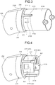
- FIG. 3 is a perspective view of a state in which a distal end base 2133 of the bending section 213 is connected to the hard member 212, when viewed from the proximal end side.
- FIG. 4 is a perspective view of the hard member 212 when viewed from the proximal end side.
- FIG. 5 is a cross-sectional view taken along a line V-V of FIG. 3 .
- the hard member 212 is a hard member made of a resin material. As illustrated in FIGS. 2 to 5 , the hard member 212 includes a large diameter portion 215 ( FIGS. 2 to 4 ), an intermediate diameter portion 216 ( FIGS. 2 to 4 ), and a small diameter portion 217 ( FIGS. 4 and 5 ).
- the large diameter portion 215 is positioned on a distal end side of the hard member 212, and having a substantially columnar shape. Furthermore, as illustrated in FIG. 2 , in the large diameter portion 215, a mounting hole 2151, a treatment tool channel 2152, an imaging hole 2153, and an illumination hole 2154 are formed.
- the ultrasound probe 211 is mounted into the mounting hole 2151, the treatment tool channel 2152 protrudes, to the outside, various treatment tools inserted through the treatment tool insertion passage, the imaging hole 2153 having an optical system, an imaging sensor, or the like disposed therein, and imaging inside the subject, and the illumination hole 2154 illuminates inside the subject with illumination light supplied from the light source device 6.
- the intermediate diameter portion 216 has a substantially columnar shape having an outer diameter smaller than that of the large diameter portion 215, and is integrally formed on a proximal end side of the large diameter portion 215, coaxially with the large diameter portion 215.
- the small diameter portion 217 has a substantially columnar shape having an outer diameter smaller than that of the intermediate diameter portion 216, and is integrally formed on a proximal end side of the intermediate diameter portion 216, coaxially with the intermediate diameter portion 216. Furthermore, the small diameter portion 217 has a function as the fitting portion according to the present invention. As illustrated in FIGS. 2 to 5 , two dam portions 2171, two storage portions 2172 ( FIG. 4 ), a swaging recess portion 2173 ( FIGS. 4 and 5 ), a housing portion 2174 ( FIGS. 4 and 5 ), and a cut-out portion 2175 ( FIGS. 4 and 5 ) are formed, in the small diameter portion 217.
- the two dam portions 2171 are formed at positions on the outer surface of the small diameter portion 217, slightly displaced from positions opposite to each other about a central axis of the small diameter portion 217. That is, the outer surface of the small diameter portion 217 is divided into a first area Ar1 ( FIGS. 4 and 5 ), and a second area Ar2 ( FIGS. 4 and 5 ) having an area smaller than that of the first area Ar1, by the two dam portions 2171. Since the two dam portions 2171 have the same shape, hereinafter, the shape of only one of the dam portions 2171 will be described.
- the dam portion 2171 is a projection projecting from the outer surface of the small diameter portion 217, and has a shape having one end connected to the intermediate diameter portion 216, and linearly extending toward the proximal end side from the one end, along the central axis of the small diameter portion 217 (corresponding to "axial direction of the insertion section" according to the present invention). Furthermore, the dam portion 2171 has a function of blocking the adhesive applied on the outer surface of the small diameter portion 217 and flowing to the cut-out portion 2175.
- the two storage portions 2172 are continuously provided to the two dam portions 2171, in the outer surface of the small diameter portion 217.
- FIG. 4 only one storage portion 2172 of the two storage portions 2172 is illustrated for convenience of description. Furthermore, since the two storage portions 2172 have the same shape, hereinafter, the shape of only one of the storage portions 2172 will be described.
- the storage portion 2172 is a recessed portion provided in the outer surface of the small diameter portion 217, and continuously provided on the proximal end side of the dam portion 2171 (corresponding to "the leading end side of the fitting portion” according to the present invention) so that the storage portion 2172 partially opposed to the other end of the dam portion 2171. Furthermore, the storage portion 2172 has a function of partially storing the adhesive blocked by the dam portion 2171.
- the dam portion 2171 and the storage portion 2172 described above constitute an unnecessary-adhesion preventing structure S1 according to the present invention ( FIG. 4 ).
- the swaging recess portion 2173 is a recessed portion provided in the second area Ar2 of the first and second areas Ar1 and Ar2, on the outer surface of the small diameter portion 217. Furthermore, the swaging recess portion 2173 partially constitutes a connection structure S2 according to the present invention ( FIGS. 4 and 5 ).
- the housing portion 2174 extends inward from an end surface of the small diameter portion 217 (corresponding to "the leading end of the fitting portion” according to the present invention). Furthermore, the housing portion 2174 communicates with the mounting hole 2151, the treatment tool channel 2152, the imaging hole 2153, and the illumination hole 2154 disposed in the large diameter portion 215. That is, the housing portion 2174 is a portion through which the light guide and the plurality of signal cables provided inside the insertion section 21, and the treatment tool are inserted.
- the cut-out portion 2175 is formed by cutting out a portion of the small diameter portion 217 from the end surface to the intermediate diameter portion 216, to communicate inside and outside of the housing portion 2174 with each other. Furthermore, the cut-out portion 2175 is provided in the second area Ar2 of the first and second areas Ar1 and Ar2, on the outer surface of the small diameter portion 217.
- the bending section 213 includes a proximal end base 2131 ( FIG. 2 ), a plurality of ring-shaped members 2132 ( FIG. 2 ), and the distal end base 2133.
- the proximal end base 2131 has a cylindrical shape, and is connected to the flexible tube portion 214, on the proximal end side.
- adjacent ring-shaped members 2132 are partially connected by pins P turnably (vertically turnably in FIG. 2 ) to have a substantially cylindrical shape as a whole, and the plurality of ring-shaped members 2132 is connected to the proximal end base 2131 on the proximal end side.
- the distal end base 2133 is made of a metal material such as stainless steel. Furthermore, the distal end base 2133 is formed into a cylindrical shape having an inner diameter slightly larger than the outer diameter of the small diameter portion 217, and an outer diameter substantially the same as the outer diameter of the intermediate diameter portion 216, and the proximal end side of the distal end base 2133 is connected by pins P turnably (vertically turnably in FIG. 2 ), on the distal end side of the plurality of ring-shaped members 2132.
- the distal end base 2133 has a function as the connection member according to the present invention.
- proximal end base 2131 proximal end base 2131, plurality of ring-shaped members 2132, and distal end base 2133
- two angle wires are inserted, in addition to the light guide, the plurality of signal cables, and the treatment tool.
- the two angle wires each have one end connected to the bending knob 221, and the other end connected to the distal end base 2133. That is, when the physician or the like operates the bending knob 221, the two angle wires are appropriately pulled and released, and the bending section 213 is bent in an upward direction or a downward direction, in FIG. 2 .
- two opening portions 2134 and a swaging tab portion 2135 are formed, in the distal end base 2133.
- the two opening portions 2134 are portions formed by cutting out the distal end base 2133 from the distal end side, to receive insertion of the two dam portions 2171, and the two opening portions 2134 are provided at positions corresponding to the two dam portions 2171 in the small diameter portion 217.
- the swaging tab portion 2135 is a portion having a base end portion connected to the distal end base 2133, and a leading end portion separated from the distal end base 2133 and swaged onto the swaging recess portion 2173, and the swaging tab portion 2135 is provided at a position corresponding to the swaging recess portion 2173 in the small diameter portion 217.
- the swaging tab portion 2135 is formed by cutting the distal end base 2133 into U-shape so that the leading end portion is directed toward the proximal end side.
- the above-mentioned swaging tab portion 2135 and swaging recess portion 2173 constitute the connection structure S2 of the present invention ( FIG. 5 ).
- the worker applies the adhesive to the first area Ar1 on the outer surface of the small diameter portion 217.
- the adhesive is not applied to the second area Ar2. That is, the first area Ar1 corresponds to an application area according to the present invention. Furthermore, the second area Ar2 corresponds to a non-application area according to the present invention.
- the worker positions the two opening portions 2134 to the two dam portions 2171 to fit the small diameter portion 217 into the distal end base 2133.
- the hard member 212 and the distal end base 2133 are connected to each other.
- first and second connector portions 241 and 242 Structures of the first and second connector portions 241 and 242 will be described below.
- FIG. 6 is a perspective view illustrating an internal structure of the first connector portion 241.
- the first and second connector portions 241 and 242 have a substantially similar shape. Therefore, only a structure of the first connector portion 241 will be described below.
- the first connector portion 241 is an electrical connector for electrically connecting a signal cable inserted into the universal cable 23, and the ultrasound cable 31. As illustrated in FIG. 6 , the first connector portion 241 has a cylindrical shape covering a terminal Te (see FIG. 8 ) electrically connected to the ultrasound cable 31.
- the terminal Te is disposed to liquid-tightly seal the inside of the first connector portion 241 with an O-ring or the like.
- the first connector portion 241 includes a connection portion 2411 connected to a connector portion (not illustrated) of the ultrasound cable 31, and a protruding portion 2412 protruding outward from a proximal end (lower end portion in FIG. 6 ) of the connection portion 2411. Furthermore, in the first connector portion 241, an aperture 240B (see FIG. 6 ) is formed in a connector case 240A (see FIG. 8 ) constituting the connector 24, and the protruding portion 2412 is fitted into the aperture 240B to liquid-tightly seal the aperture 240B with an O-ring or the like.
- connection portion 2411 has an inner surface, and a cylindrical sleeve 2413 is liquid-tightly mounted on the inner surface with an O-ring or the like.
- connection portion 2411 two locking pins 2414 for locking a connector cap 244 (see FIG. 7 ) to the first connector portion 241 are mounted so that the locking pins 2414 project from an outer surface of the connection portion 2411.
- the ultrasound cable 31, the video cable 41, and the optical fiber cable 61 are removed from the first to third connector portions 241 to 243, and so-called autoclave sterilization or sterilization by antiseptic solution is performed thereon, before ultrasonic diagnosis in the subject, Upon sterilization, water or liquid such as the antiseptic solution tends to enter the first and second connector portions 241 and 242.
- the third connector portion 243 does not have an opened connector structure (structure in which water or liquid such as the antiseptic solution easily enter).
- the connector caps 244 are mounted to the first and second connector portions 241 and 242.
- the connector caps 244 mounted to the first and second connector portions 241 and 242 have a substantially similar structure. Therefore, only a structure of the connector cap 244 mounted to the first connector portion 241 will be described below.
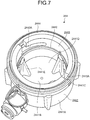
- FIG. 7 is a perspective view illustrating an internal structure of the connector cap 244 mounted to the first connector portion 241.
- FIG. 8 is a cross-sectional view of a state in which the connector cap 244 is mounted to the first connector portion 241.
- the connector cap 244 includes a cap body 2441, a first packing 2442, a cam body 2443, and a second packing 2444.
- the cap body 2441 is formed into a container shape including a cylindrical side wall portion 2441A for inserting the connection portion 2411 therein, and a bottom portion 2441B closing one end of the side wall portion 2441A, and having an opening portion 2441C in the other end of the side wall portion 2441A.
- the bottom portion 2441B has an inner surface 2441D (bottom surface of the cap body 2441) on which standing ribs 2441E are provided. Furthermore, as illustrated in FIG. 8 , each of the ribs 2441E is positioned to have a predetermined gap between a leading end of the rib 2441E and a leading end of the sleeve 2413 (upper end portion in FIGS. 6 and 8 ), upon mounting the connector cap 244 to the first connector portion 241.
- the first packing 2442 has a ring shape, and mounted on an inner surface of the side wall portion 2441A. Furthermore, as illustrated in FIG. 8 , when the connector cap 244 is mounted to the first connector portion 241, the first packing 2442 makes contact with the outer surface of the connection portion 2411 to maintain liquid tightness in the first connector portion 241.
- the cam body 2443 has a cylindrical shape for inserting the connection portion 2411 therein, and is mounted on the inner surface of the side wall portion 2441A, on the side of the opening portion 2441C. As illustrated in FIG. 7 , in the cam body 2443, two locking grooves 2443A are formed, and two locking pins 2414 are respectively inserted into the two locking grooves 2443A.
- each of the two locking grooves 2443A has a substantially L-shape extending from one end (end portion on the side of the opening portion 2441C) to the other end (end portion on the side of the bottom portion 2441B), and extending in a rotation direction about a central axis of the cam body 2443 (not illustrated). That is, in the first embodiment, as a locking structure between the first connector portion 241 and the connector cap 244, a bayonet locking structure is employed.
- the second packing 2444 has a ring shape, and is mounted in the opening portion 2441C to be partially inserted into a gap between the cam body 2443 and the inner surface of the side wall portion 2441A. Furthermore, as illustrated in FIG. 8 , when the connector cap 244 is mounted to the first connector portion 241, the second packing 2444 makes contact with the protruding portion 2412 to maintain liquid tightness in the first connector portion 241.
- the first connector portion 241 and connector cap 244 described above is designed to have the following dimensional relationship for each product type of the endoscope 2.
- the first connector portion 241 and connector cap 244 are designed to have a dimensional relationship satisfying the following formula (1).
- Specified value Va D 1 + D 2
- the specified value Va varies depending on product types of the endoscope 2.
- FIG. 9 is a cross-sectional view of a state in which a first connector portion 241' and a connector cap 244' of different product types are connected to each other.
- the worker who mounts the connector cap 244 or 244' to the first connector portion 241 or 241' can determine that the connector cap 244 of the same product type is mounted, when the slight gap is generated, and that the connector cap 244' of different product type is mounted, when the larger gap is generated.
- each portion is designed to be appropriately set so that a rib 2441E' makes contact with a leading end of a sleeve 2413' to maintain liquid tightness in the first connector portion 241', as illustrated in FIG. 9 .
- the cut-out portion 2175 is formed by cutting out the portion of the small diameter portion 217 from the end surface to communicate inside and outside of the housing portion 2174 with each other. Therefore, the wall thickness of part of the small diameter portion 217 (part of a portion surrounding the housing portion 2174) can be removed, and reduction in diameter (reduction in size) of the small diameter portion 217 can be achieved due to the removed wall thickness.
- the small diameter portion 217 is provided with the unnecessary-adhesion preventing structure S1 having the dam portion 2171 and the storage portion 2172. Therefore, even if the adhesive flows out along the outer surface of the small diameter portion 217, the dam portion 2171 can prevent the adhesive from flowing toward the cut-out portion 2175. That is, the adhesive is prevented from adhering to the light guide, the plurality of signal cables, or the treatment tool disposed in the housing portion 2174, through the cut-out portion 2175.
- the storage portion 2172 is continuously provided on the proximal end side relative to the dam portion 2171, and since the storage portion 2172 partially stores the adhesive blocked by the dam portion 2171, the adhesive can be also prevented from flowing to the end surface of the small diameter portion 217, and adhering to the light guide, the plurality of signal cables, or the treatment tool disposed in the housing portion 2174.
- the size of the hard member 212 can be reduced, and the adhesive can be prevented from adhering to the light guide, the plurality of signal cables, or the treatment tool disposed in the hard member 212, in an effective manner.
- the small diameter portion 217 and the distal end base 2133 are provided with the connection structure S2. Therefore, the hard member 212 and the distal end base 2133 can be secured to each other with the connection structure S2, in addition to the adhesive, and the hard member 212 and the distal end base 2133 can be firmly secured to each other.
- connection structure S2 is provided in the second area Ar2 as the non-application area to which no adhesive is applied. Therefore, in comparison with a configuration having the connection structure S2 provided in the first area Ar1 as the application area to which the adhesive is applied, when a component of the hard member 212 or the distal end base 2133 is changed, the hard member 212 and the distal end base 2133 can be readily removed.
- the recessed portion (storage portion 2172) formed in the outer surface of the small diameter portion 217 is employed.
- a porous member provided independently of a hard member and a distal end base is employed as the storage portion according to the present invention.
- a distal end base according to the second embodiment has a configuration similar to that of the distal end base 2133 described in the first embodiment.
- FIG. 10 is an exploded perspective view schematically illustrating a hard member 212A and the distal end base 2133 according to the second embodiment of the present invention.
- the hard member 212A has a configuration similar to that of the hard member 212 described in the above first embodiment, except for the storage portion 2172.
- FIG. 10 as the configuration of the hard member 212A, only one dam portion 2171 is illustrated while the swaging recess portion 2173, the housing portion 2174, and the cut-out portion 2175 is not illustrated for convenience of explanation. As a configuration of the distal end base 2133, only one opening portion 2134 is illustrated while the swaging tab portion 2135 is not illustrated.
- a storage portion 2172A is mounted to be continuously provided on the proximal end side of the dam portion 2171, as illustrated in FIG. 10 .
- the storage portion 2172A is made of sponge or the like having a width substantially the same as that of the dam portion 2171 to be inserted into the opening portion 2134.
- the storage portion 2172A has a function similar to the function of the storage portion 2172 described in the first embodiment.
- dam portion 2171 and the storage portion 2172 A constitute an unnecessary-adhesion preventing structure S1A according to the present invention ( FIG. 10 ).
- FIG. 11 is a diagram illustrating modification 2-1 of the second embodiment of the present invention.
- FIG. 11 is a figure corresponds to FIG. 10 .
- the storage portion 2172A is mounted to the hard member 212A, but is not limited to this configuration, and may be mounted to the proximal end side of the opening portion 2134, that is, to the distal end base 2133, as illustrated in FIG. 11 .
- the dam portion 2171 is integrally formed on the hard member 212A, but is not limited to this configuration, and may be provided independently of the hard member 212A to be mounted to the hard member 212A, similarly to the storage portion 2172A.
- a material of the dam portion 2171 provided independently of the hard member 212A may be the same as that of the hard member 212A, or may be different from that of the hard member 212A.
- the dam portion 2171 in the above first embodiment may also be provided independently of the hard member 212.
- the projection (dam portion 2171) projecting from the outer surface of the small diameter portion 217 is employed, as the dam portion according to the present invention.
- the dam portion according to the present invention is integrally formed with the distal end base.
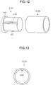
- FIG. 12 is an exploded perspective view schematically illustrating a hard member 212B and a distal end base 2133B according to the third embodiment of the present invention.
- the hard member 212B has a configuration similar to that of the hard member 212 described in the first embodiment, except that the two dam portions 2171 and the two storage portions 2172 are not provided, and instead, groove portions 2176 ( FIG. 12 ) are formed at positions where the dam portions 2171 and storage portions 2172 are provided.
- FIG. 12 as a configuration of the hard member 212B, only one of the two groove portions 2176 is illustrated while the swaging recess portion 2173, the housing portion 2174, and the cut-out portion 2175 are not illustrated for convenience of description.
- the groove portion 2176 is formed to linearly extend from the end surface of the small diameter portion 217 to the intermediate diameter portion 216, along the central axis of the small diameter portion 217.
- FIG. 13 is a diagram of the distal end base 2133B viewed from a direction along the central axis.
- the distal end base 2133B has a configuration similar to that of the distal end base 2133 described in the first embodiment, except that the two opening portions 2134 are not provided, and instead, dam portions 2136 ( FIG. 13 ) are formed at positions where the opening portions 2134 are provided.
- FIGS. 12 and 13 as a configuration of the distal end base 2133B, only one of the two dam portions 2136 is illustrated while the swaging tab portion 2135 is not illustrated for convenience of description.
- the dam portion 2136 is a projection projecting from an inner surface of the distal end base 2133B, and inserted into the groove portion 2176, and has a shape linearly extending from one end of the distal end base 2133B (end portion on the distal end side) to the other end of the distal end base 2133B (end portion on the proximal end side), along the central axis of the distal end base 2133B.
- the dam portion 2136 has a function similar to that of the dam portion 2171 described in the first embodiment.
- a connection method for the hard member 212B and the distal end base 2133B is similar to the connection method for the hard member 212 and the distal end base 2133 described in the first embodiment, except that the two dam portions 2136 are positioned to the two groove portions 2176.
- FIG. 14 is a cross-sectional view of a state in which the distal end base 2133B is connected to the hard member 212B.
- FIG. 14 illustrates a state in which the dam portion 2136 is inserted into the groove portion 2176.
- the dam portion 2136 is formed to have a length smaller than a length of the groove portion 2176. Therefore, while the distal end base 2133B is connected to the hard member 212B, a distal end side of the dam portion 2136 makes contact with the intermediate diameter portion 216, and a space 2137 in which the dam portion 2136 is not disposed is formed on a proximal end side of the groove portion 2176.
- This space 2137 has a function similar to that of the storage portion 2172 described in the first embodiment.
- dam portion 2136 and the space 2137 constitute an unnecessary-adhesion preventing structure S1B ( FIG. 14 ) according to the present invention.
- the storage portion 2172A described in the above second embodiment may be mounted on the inner surface of the distal end base 2133B to be continuously provided on a proximal end side of the dam portion 2136.
- the dam portion 2136 may be provided independently of the distal end base 2133B to be mounted on the inner surface of the distal end base 2133B, similarly to modification 2-2 of the above second embodiment.
- the endoscope system 1 has both of the function of generating the ultrasound image, and the function of generating the endoscopic image, but the endoscope system 1 is not limited to this configuration, and may be configured to have only one of the functions.
- the endoscope system 1 is not limited to medical field use, and the endoscope system 1 may be used in an industrial field, to be used as an endoscope system for observing inside a subject such as a machine structure.
Landscapes
- Health & Medical Sciences (AREA)
- Life Sciences & Earth Sciences (AREA)
- Surgery (AREA)
- Physics & Mathematics (AREA)
- Optics & Photonics (AREA)
- Engineering & Computer Science (AREA)
- Biophysics (AREA)
- Animal Behavior & Ethology (AREA)
- Pathology (AREA)
- Radiology & Medical Imaging (AREA)
- Veterinary Medicine (AREA)
- Biomedical Technology (AREA)
- Heart & Thoracic Surgery (AREA)
- Medical Informatics (AREA)
- Molecular Biology (AREA)
- Nuclear Medicine, Radiotherapy & Molecular Imaging (AREA)
- General Health & Medical Sciences (AREA)
- Public Health (AREA)
- Manufacturing & Machinery (AREA)
- Astronomy & Astrophysics (AREA)
- General Physics & Mathematics (AREA)
- Endoscopes (AREA)
- Instruments For Viewing The Inside Of Hollow Bodies (AREA)
Abstract
Description
- The present invention relates to an endoscope and a hard member.
- Conventionally, endoscopes have been known in which a soft and elongated insertion section is inserted into a subject such as a human to observe inside the subject (e.g., see Patent Literature 1).
- In an endoscope described in
Patent Literature 1, an insertion section includes a connection tube (hereinafter, referred to as connection member) being a cylindrical metal member, and a distal end portion (hereinafter, referred to as hard member) positioned on a distal end side of the insertion section relative to the connection member, and secured to the connection member. Furthermore, the hard member is secured to the connection member with screws, while partially fitted into the connection member (hereinafter, referred to as fitting portion). - Patent Literature 1:
JP 2009-18080 A - Considering that the hard member is a portion exposed in the subject such as a human, a resin material is commonly employed as the hard member. Furthermore, such a hard member made of resin and the connection member are secured to each other with screws as described in
Patent Literature 1, a load is applied to the hard member due to the screws, and the hard member may be broken. - Thus, the following structure can be provided as a structure for securing the hard member made of resin to the connection member without applying a load on the hard member.
- That is, while an adhesive is applied to an outer surface of the fitting portion in the hard member, the fitting portion is fitted into the connection member. That is, this is a structure for securing the hard member made of resin to the connection member with an adhesive.
- The fitting portion has therein a housing portion which extends inward from a leading end and through which a cable and the like is inserted. Therefore, there is a problem that when the structure described above is adopted, the adhesive may flow out along the outer surface of the fitting portion to a leading end of the fitting portion, and the adhesive consequently adheres to internal components such as cables disposed in the housing portion.
- Furthermore, there is a problem that when the housing portion is formed into a shape simply extending from the leading end of the fitting portion to the inside of the fitting portion, as described above, reduction in diameter (reduction in size) of the fitting portion (hard member) is inhibited due to a wall thickness of the fitting portion (wall thickness of a portion surrounding the housing portion).
- The present invention has been made in view of the foregoing, and an object of the present invention is to provide an endoscope and a hard member capable of achieving a small-sized hard member and preventing adhesion of an adhesive to internal components disposed in the hard member.
- In order to solve the above described problem and achieve the object, an endoscope according to the invention includes an insertion section configured to be inserted into a subject to observe an inside of the subject. The insertion section includes: a cylindrical connection member; and a hard member having a fitting portion fitted into the connection member and secured to the connection member with an adhesive applied on an outer surface of the fitting portion. The fitting portion includes: a housing portion extending from a leading end of the fitting portion to an inside of the fitting portion; and a cut-out portion formed by cutting out part of the fitting portion from the leading end to communicate inside and outside of the housing portion with each other. At least one of the fitting portion and the connection member includes an unnecessary-adhesion preventing structure having: a dam portion extending in an axial direction of the insertion section along the outer surface of the fitting portion to block the adhesive flowing to the cut-out portion along the outer surface of the fitting portion; and a storage portion continuously provided to the dam portion to partially store the adhesive blocked by the dam portion.
- In the endoscope according to the invention, the dam portion is provided on the outer surface of the fitting portion, and the connection member includes an opening portion into which the dam portion is inserted when the fitting portion is fitted into the connection member.
- In the endoscope according to the invention, the storage portion is a recessed portion provided on the outer surface of the fitting portion.
- In the endoscope according to the invention, the storage portion is provided independently of the fitting portion and the connection member, and is made of a porous member.
- In the endoscope according to the invention, the storage portion is continuously provided on a leading end side of the fitting portion relative to the dam portion.
- In the endoscope according to the invention, the dam portion is provided on an inner surface of the connection member. The fitting portion has a groove portion on the outer surface of the fitting portion, the groove portion extending in the axial direction of the insertion section from the leading end of the fitting portion, and the dam portion being inserted into the groove portion when the fitting portion is fitted into the connection member.
- In the endoscope according to the invention, the dam portion has a length smaller than a length of the groove portion, and the groove portion has a space in which the dam portion is not disposed to define the storage portion when the fitting portion is fitted into the connection member.
- In the endoscope according to the invention, the fitting portion and the connection member include a connection structure for connecting the fitting portion to the connection member by swaging part of the connection member onto the outer surface of the fitting portion.
- In the endoscope according to the invention, the at least one of the fitting portion and the connection member further includes one additional dam portion to define two dam portions. The two dam portions separate the outer surface of the fitting portion into an application area to which the adhesive is applied and a non-application area to which no adhesive is applied. The cut-out portion and the connection structure are located in the non-application area.
- A hard member according to the invention is used for an insertion section of an endoscope for observing an inside a subject, and is secured to a cylindrical connection member. The hard member includes a fitting portion fitted into the connection member and secured to the connection member with an adhesive applied on an outer surface of the fitting portion. The fitting portion includes: a housing portion extending from a leading end of the fitting portion to an inside of the fitting portion; a cut-out portion formed by cutting out part of the fitting portion from the leading end to communicate inside and outside of the housing portion with each other; a dam portion extending in an axial direction of the insertion section along the outer surface of the fitting portion to block the adhesive flowing to the cut-out portion along the outer surface of the fitting portion; and a storage portion continuously provided to the dam portion to partially store the adhesive blocked by the dam portion.
- In the hard member according to the invention, the storage portion is a recessed portion provided on the outer surface of the fitting portion.
- In the hard member according to the invention, the storage portion is provided independently of the fitting portion, and is made of a porous member.
- In the hard member according to the invention, the storage portion is continuously provided on a leading end side of the fitting portion relative to the dam portion.
- An endoscope according to the present invention includes a fitting portion (hard member) having a cut-out portion. The cut-out portion is formed by cutting out part of the fitting portion from the leading end to communicate inside and outside of the housing portion with each other. It is therefore possible to reduce a wall thickness of part of the fitting portion (part of a portion surrounding the housing portion) can be removed, thereby to achieve a small-sized fitting portion (hard member).
- Furthermore, according to the endoscope of the present invention, at least one of the fitting portion and a connection member includes an unnecessary-adhesion preventing structure having a dam portion and a storage portion. With this structure, even if the adhesive flows out along an outer surface of the fitting portion, the dam portion can prevent the adhesive from flowing toward the cut-out portion. That is, the adhesive is prevented from adhering to the internal components disposed in the housing portion through the cut-out portion. Furthermore, since the storage portion partially stores the adhesive blocked by the dam portion, the adhesive can be also prevented from flowing to the leading end of the fitting portion and adhering to the internal components disposed in the housing portion.
- Thus, according to the endoscope of the present invention, it is possible to achieve a small-sized hard member, and to prevent the adhesive from adhering to the internal components disposed in the hard member, in an effective manner.
- Because the hard member according to the present invention is used for the endoscope described above, similar effects to those of the endoscope described above can be obtained.
-
-
FIG. 1 is a schematic view of an endoscope system according to a first embodiment of the present invention. -
FIG. 2 is an enlarged perspective view of a distal end side of an insertion section illustrated inFIG. 1 . -
FIG. 3 is a perspective view of a state in which a distal end base of a bending section illustrated inFIGS. 1 and2 is connected to a hard member illustrated inFIGS. 1 and2 , when viewed from a proximal end side. -
FIG. 4 is a perspective view of the hard member illustrated inFIGS. 1 to 3 , when viewed from the proximal end side. -
FIG. 5 is a cross-sectional view taken along a line V-V ofFIG. 3 . -
FIG. 6 is a perspective view illustrating an internal structure of a first connector portion illustrated inFIG. 1 . -
FIG. 7 is a perspective view illustrating an internal structure of a connector cap mounted to the first connector portion illustrated inFIG. 6 . -
FIG. 8 is a cross-sectional view of a state in which the connector cap illustrated inFIG. 7 is mounted to the first connector portion illustrated inFIG. 6 . -
FIG. 9 is a cross-sectional view of a state in which a first connector portion and a connector cap of different product types are connected to each other. -
FIG. 10 is an exploded perspective view schematically illustrating a hard member and a distal end base according to a second embodiment of the present invention. -
FIG. 11 is a diagram illustrating modification 2-1 of the second embodiment of the present invention. -
FIG. 12 is an exploded perspective view schematically illustrating a hard member and a distal end base according to a third embodiment of the present invention. -
FIG. 13 is a diagram of the distal end base illustrated inFIG. 12 , viewed from a direction along a central axis. -
FIG. 14 is a cross-sectional view of a state in which the distal end base illustrated inFIG. 12 or 13 is connected to a hard member illustrated inFIG. 12 . Description of Embodiments - Modes for carrying out the present invention (hereinafter referred to as "embodiment(s)") will be described below with reference to the drawings. The present invention is not limited to the embodiments described below. The same reference signs are used to designate the same elements throughout the drawings.
-
FIG. 1 is a schematic view of anendoscope system 1 according to a first embodiment of the present invention. - The
endoscope system 1 is a system performing ultrasonic diagnosis in a subject such as a human, using an ultrasound endoscope. As illustrated inFIG. 1 , theendoscope system 1 includes anendoscope 2, anultrasound observation device 3, anendoscope observation device 4, adisplay device 5, and a light source device 6. - The
endoscope 2 is an ultrasound endoscope configured to be partially inserted into the subject, and having a function of transmitting ultrasound pulses toward a body wall in the subject, receiving an ultrasound echo reflected from the subject, and outputting an echo signal, and a function of imaging inside the subject and outputting an image signal. - A detailed configuration of the
endoscope 2 will be described later. - The
ultrasound observation device 3 is electrically connected to theendoscope 2 through an ultrasound cable 31 (FIG. 1 ), and outputs a pulse signal to theendoscope 2 and receives an echo signal input from theendoscope 2, through theultrasound cable 31. Furthermore, theultrasound observation device 3 performs predetermined processing on the echo signal to generate an ultrasound image. - The
endoscope observation device 4 is electrically connected to theendoscope 2 through a video cable 41 (FIG. 1 ), and receives an image signal input from theendoscope 2 through thevideo cable 41. Furthermore, theendoscope observation device 4 performs predetermined processing on the image signal to generate an endoscopic image. - The
display device 5 is configured using liquid crystal or organic electro luminescence (EL), and displays the ultrasound image generated in theultrasound observation device 3, the endoscopic image generated in theendoscope observation device 4, or the like. - The light source device 6 is connected to the
endoscope 2 through an optical fiber cable 61 (FIG. 1 ), and supplies illumination light illuminating inside the subject, to theendoscope 2, through theoptical fiber cable 61. - As illustrated in
FIG. 1 , theendoscope 2 includes aninsertion section 21, an operatingunit 22, auniversal cable 23, and aconnector 24. - Note that, "distal end side" described below represents a distal end side of the
insertion section 21. In addition, "proximal end side" described below represents a side away from the distal end of theinsertion section 21. - The
insertion section 21 is a portion inserted into the subject. As illustrated inFIG. 1 , theinsertion section 21 includes anultrasound probe 211 provided on the distal end side, ahard member 212 connected to the proximal end side of theultrasound probe 211, abending section 213 connected on the proximal end side of thehard member 212 to be bendable, and aflexible tube portion 214 connected to the proximal end side of thebending section 213. - Although not specifically illustrated, the
insertion section 21 has therein a light guide for transmitting illumination light supplied from the light source device 6, a plurality of signal cables for transmitting various signals, and a treatment tool insertion passage through which a treatment tool is inserted. - A detailed configuration of the distal end side of the insertion section 21 (the
ultrasound probe 211, thehard member 212, and the bending section 213) will be described later. - The operating
unit 22 is a portion connected to the proximal end side of theinsertion section 21, and receives various operation from a physician or the like. As illustrated inFIG. 1 , the operatingunit 22 includes a bendingknob 221 for bendably operating thebending section 213, and a plurality ofoperation members 222 for performing various operations. - Furthermore, in the operating
unit 22, a treatmenttool insertion opening 223 is formed. The treatmenttool insertion opening 223 communicates with the treatment tool insertion passage formed in theinsertion section 21, and inserts a treatment tool through the treatment tool insertion passage. - The
universal cable 23 is a cable extending from the operatingunit 22, and the signal cables for transmitting various signals, an optical fiber for transmitting illumination light supplied from the light source device 6, and the like are disposed therein. - The
connector 24 is provided at a distal end of theuniversal cable 23. Furthermore, theconnector 24 includes first tothird connector portions 241 to 243 to which theultrasound cable 31, thevideo cable 41, and theoptical fiber cable 61 are respectively connected. - A detailed configuration of the first and
second connector portions -
FIG. 2 is an enlarged perspective view of the distal end side of theinsertion section 21. - Configurations of the
ultrasound probe 211, thehard member 212, and thebending section 213 will be sequentially described below. - As illustrated in
FIG. 2 , theultrasound probe 211 is a convex ultrasound probe, and has atransducer unit 2111 in which multiple ultrasound transducers are regularly disposed to form a convex arcuate shape. - Here, an ultrasound transducer has an acoustic lens, a piezoelectric element, and a matching layer, and obtains an ultrasound echo contributing to an ultrasound tomographic image captured inside the body wall in the subject.
- The
transducer unit 2111 converts the pulse signal, which is input from theultrasound observation device 3 through the signal cable provided inside theinsertion section 21, into ultrasound pulses, and transmits the ultrasound pulses to the subject. Furthermore, thetransducer unit 2111 converts the ultrasound echo reflected from the subject into an electrical echo signal, and outputs the echo signal to theultrasound observation device 3 through the signal cable provided inside theinsertion section 21. -
FIG. 3 is a perspective view of a state in which adistal end base 2133 of thebending section 213 is connected to thehard member 212, when viewed from the proximal end side.FIG. 4 is a perspective view of thehard member 212 when viewed from the proximal end side.FIG. 5 is a cross-sectional view taken along a line V-V ofFIG. 3 . - The
hard member 212 is a hard member made of a resin material. As illustrated inFIGS. 2 to 5 , thehard member 212 includes a large diameter portion 215 (FIGS. 2 to 4 ), an intermediate diameter portion 216 (FIGS. 2 to 4 ), and a small diameter portion 217 (FIGS. 4 and5 ). - As illustrated in
FIGS. 2 to 4 , thelarge diameter portion 215 is positioned on a distal end side of thehard member 212, and having a substantially columnar shape. Furthermore, as illustrated inFIG. 2 , in thelarge diameter portion 215, a mountinghole 2151, atreatment tool channel 2152, animaging hole 2153, and anillumination hole 2154 are formed. Theultrasound probe 211 is mounted into the mountinghole 2151, thetreatment tool channel 2152 protrudes, to the outside, various treatment tools inserted through the treatment tool insertion passage, theimaging hole 2153 having an optical system, an imaging sensor, or the like disposed therein, and imaging inside the subject, and theillumination hole 2154 illuminates inside the subject with illumination light supplied from the light source device 6. - As illustrated in
FIGS. 2 to 4 , theintermediate diameter portion 216 has a substantially columnar shape having an outer diameter smaller than that of thelarge diameter portion 215, and is integrally formed on a proximal end side of thelarge diameter portion 215, coaxially with thelarge diameter portion 215. - As illustrated in
FIG. 4 or5 , thesmall diameter portion 217 has a substantially columnar shape having an outer diameter smaller than that of theintermediate diameter portion 216, and is integrally formed on a proximal end side of theintermediate diameter portion 216, coaxially with theintermediate diameter portion 216. Furthermore, thesmall diameter portion 217 has a function as the fitting portion according to the present invention. As illustrated inFIGS. 2 to 5 , twodam portions 2171, two storage portions 2172 (FIG. 4 ), a swaging recess portion 2173 (FIGS. 4 and5 ), a housing portion 2174 (FIGS. 4 and5 ), and a cut-out portion 2175 (FIGS. 4 and5 ) are formed, in thesmall diameter portion 217. - As illustrated in
FIG. 5 , the twodam portions 2171 are formed at positions on the outer surface of thesmall diameter portion 217, slightly displaced from positions opposite to each other about a central axis of thesmall diameter portion 217. That is, the outer surface of thesmall diameter portion 217 is divided into a first area Ar1 (FIGS. 4 and5 ), and a second area Ar2 (FIGS. 4 and5 ) having an area smaller than that of the first area Ar1, by the twodam portions 2171. Since the twodam portions 2171 have the same shape, hereinafter, the shape of only one of thedam portions 2171 will be described. - As illustrated in
FIGS. 2 to 5 , thedam portion 2171 is a projection projecting from the outer surface of thesmall diameter portion 217, and has a shape having one end connected to theintermediate diameter portion 216, and linearly extending toward the proximal end side from the one end, along the central axis of the small diameter portion 217 (corresponding to "axial direction of the insertion section" according to the present invention). Furthermore, thedam portion 2171 has a function of blocking the adhesive applied on the outer surface of thesmall diameter portion 217 and flowing to the cut-out portion 2175. - As illustrated in
FIG. 4 , the twostorage portions 2172 are continuously provided to the twodam portions 2171, in the outer surface of thesmall diameter portion 217. InFIG. 4 , only onestorage portion 2172 of the twostorage portions 2172 is illustrated for convenience of description. Furthermore, since the twostorage portions 2172 have the same shape, hereinafter, the shape of only one of thestorage portions 2172 will be described. - As illustrated in
FIG. 4 , thestorage portion 2172 is a recessed portion provided in the outer surface of thesmall diameter portion 217, and continuously provided on the proximal end side of the dam portion 2171 (corresponding to "the leading end side of the fitting portion" according to the present invention) so that thestorage portion 2172 partially opposed to the other end of thedam portion 2171. Furthermore, thestorage portion 2172 has a function of partially storing the adhesive blocked by thedam portion 2171. - The
dam portion 2171 and thestorage portion 2172 described above constitute an unnecessary-adhesion preventing structure S1 according to the present invention (FIG. 4 ). - As illustrated in
FIG. 4 or5 , theswaging recess portion 2173 is a recessed portion provided in the second area Ar2 of the first and second areas Ar1 and Ar2, on the outer surface of thesmall diameter portion 217. Furthermore, theswaging recess portion 2173 partially constitutes a connection structure S2 according to the present invention (FIGS. 4 and5 ). - As illustrated in
FIG. 4 or5 , thehousing portion 2174 extends inward from an end surface of the small diameter portion 217 (corresponding to "the leading end of the fitting portion" according to the present invention). Furthermore, thehousing portion 2174 communicates with the mountinghole 2151, thetreatment tool channel 2152, theimaging hole 2153, and theillumination hole 2154 disposed in thelarge diameter portion 215. That is, thehousing portion 2174 is a portion through which the light guide and the plurality of signal cables provided inside theinsertion section 21, and the treatment tool are inserted. - As illustrated in
FIG. 4 or5 , the cut-out portion 2175 is formed by cutting out a portion of thesmall diameter portion 217 from the end surface to theintermediate diameter portion 216, to communicate inside and outside of thehousing portion 2174 with each other. Furthermore, the cut-out portion 2175 is provided in the second area Ar2 of the first and second areas Ar1 and Ar2, on the outer surface of thesmall diameter portion 217. - As illustrated in
FIGS. 2 and3 or5 , thebending section 213 includes a proximal end base 2131 (FIG. 2 ), a plurality of ring-shaped members 2132 (FIG. 2 ), and thedistal end base 2133. - The
proximal end base 2131 has a cylindrical shape, and is connected to theflexible tube portion 214, on the proximal end side. - In the plurality of ring-shaped
members 2132, adjacent ring-shapedmembers 2132 are partially connected by pins P turnably (vertically turnably inFIG. 2 ) to have a substantially cylindrical shape as a whole, and the plurality of ring-shapedmembers 2132 is connected to theproximal end base 2131 on the proximal end side. - The
distal end base 2133 is made of a metal material such as stainless steel. Furthermore, thedistal end base 2133 is formed into a cylindrical shape having an inner diameter slightly larger than the outer diameter of thesmall diameter portion 217, and an outer diameter substantially the same as the outer diameter of theintermediate diameter portion 216, and the proximal end side of thedistal end base 2133 is connected by pins P turnably (vertically turnably inFIG. 2 ), on the distal end side of the plurality of ring-shapedmembers 2132. Thedistal end base 2133 has a function as the connection member according to the present invention. - Furthermore, in the above-mentioned
proximal end base 2131, plurality of ring-shapedmembers 2132, anddistal end base 2133, two angle wires (not illustrated) are inserted, in addition to the light guide, the plurality of signal cables, and the treatment tool. The two angle wires each have one end connected to the bendingknob 221, and the other end connected to thedistal end base 2133. That is, when the physician or the like operates the bendingknob 221, the two angle wires are appropriately pulled and released, and thebending section 213 is bent in an upward direction or a downward direction, inFIG. 2 . - Furthermore, as illustrated in
FIGS. 2 and3 or 5, two openingportions 2134 and aswaging tab portion 2135 are formed, in thedistal end base 2133. - The two opening
portions 2134 are portions formed by cutting out thedistal end base 2133 from the distal end side, to receive insertion of the twodam portions 2171, and the two openingportions 2134 are provided at positions corresponding to the twodam portions 2171 in thesmall diameter portion 217. - The
swaging tab portion 2135 is a portion having a base end portion connected to thedistal end base 2133, and a leading end portion separated from thedistal end base 2133 and swaged onto theswaging recess portion 2173, and theswaging tab portion 2135 is provided at a position corresponding to theswaging recess portion 2173 in thesmall diameter portion 217. Theswaging tab portion 2135 is formed by cutting thedistal end base 2133 into U-shape so that the leading end portion is directed toward the proximal end side. - The above-mentioned
swaging tab portion 2135 andswaging recess portion 2173 constitute the connection structure S2 of the present invention (FIG. 5 ). - Next, a connection method for the above-mentioned
hard member 212 anddistal end base 2133 will be described. - First, the worker applies the adhesive to the first area Ar1 on the outer surface of the
small diameter portion 217. The adhesive is not applied to the second area Ar2. That is, the first area Ar1 corresponds to an application area according to the present invention. Furthermore, the second area Ar2 corresponds to a non-application area according to the present invention. - Next, the worker positions the two opening
portions 2134 to the twodam portions 2171 to fit thesmall diameter portion 217 into thedistal end base 2133. - Next, the worker presses the
swaging tab portion 2135 to fit theswaging tab portion 2135 into theswaging recess portion 2173. - Through the above-mentioned process, the
hard member 212 and thedistal end base 2133 are connected to each other. - Structures of the first and
second connector portions -
FIG. 6 is a perspective view illustrating an internal structure of thefirst connector portion 241. - The first and
second connector portions first connector portion 241 will be described below. - The
first connector portion 241 is an electrical connector for electrically connecting a signal cable inserted into theuniversal cable 23, and theultrasound cable 31. As illustrated inFIG. 6 , thefirst connector portion 241 has a cylindrical shape covering a terminal Te (seeFIG. 8 ) electrically connected to theultrasound cable 31. - Although not specifically illustrated, the terminal Te is disposed to liquid-tightly seal the inside of the
first connector portion 241 with an O-ring or the like. - The
first connector portion 241 includes aconnection portion 2411 connected to a connector portion (not illustrated) of theultrasound cable 31, and a protrudingportion 2412 protruding outward from a proximal end (lower end portion inFIG. 6 ) of theconnection portion 2411. Furthermore, in thefirst connector portion 241, anaperture 240B (seeFIG. 6 ) is formed in aconnector case 240A (seeFIG. 8 ) constituting theconnector 24, and the protrudingportion 2412 is fitted into theaperture 240B to liquid-tightly seal theaperture 240B with an O-ring or the like. - As illustrated in
FIG. 6 , theconnection portion 2411 has an inner surface, and acylindrical sleeve 2413 is liquid-tightly mounted on the inner surface with an O-ring or the like. - Furthermore, as illustrated in
FIG. 6 , in theconnection portion 2411, two lockingpins 2414 for locking a connector cap 244 (seeFIG. 7 ) to thefirst connector portion 241 are mounted so that the locking pins 2414 project from an outer surface of theconnection portion 2411. - In the
endoscope 2, theultrasound cable 31, thevideo cable 41, and theoptical fiber cable 61 are removed from the first tothird connector portions 241 to 243, and so-called autoclave sterilization or sterilization by antiseptic solution is performed thereon, before ultrasonic diagnosis in the subject, Upon sterilization, water or liquid such as the antiseptic solution tends to enter the first andsecond connector portions second connector portions third connector portion 243 does not have an opened connector structure (structure in which water or liquid such as the antiseptic solution easily enter). - Therefore, for disinfection or sterilization, in order to prevent entrance of a liquid into the first and
second connector portions FIG. 7 ) are mounted to the first andsecond connector portions - The connector caps 244 mounted to the first and
second connector portions connector cap 244 mounted to thefirst connector portion 241 will be described below. -
FIG. 7 is a perspective view illustrating an internal structure of theconnector cap 244 mounted to thefirst connector portion 241.FIG. 8 is a cross-sectional view of a state in which theconnector cap 244 is mounted to thefirst connector portion 241. - As illustrated in
FIG. 7 or8 , theconnector cap 244 includes acap body 2441, afirst packing 2442, acam body 2443, and asecond packing 2444. - As illustrated in
FIG. 7 or8 , thecap body 2441 is formed into a container shape including a cylindricalside wall portion 2441A for inserting theconnection portion 2411 therein, and abottom portion 2441B closing one end of theside wall portion 2441A, and having anopening portion 2441C in the other end of theside wall portion 2441A. - The
bottom portion 2441B has aninner surface 2441D (bottom surface of the cap body 2441) on which standingribs 2441E are provided. Furthermore, as illustrated inFIG. 8 , each of theribs 2441E is positioned to have a predetermined gap between a leading end of therib 2441E and a leading end of the sleeve 2413 (upper end portion inFIGS. 6 and8 ), upon mounting theconnector cap 244 to thefirst connector portion 241. - The
first packing 2442 has a ring shape, and mounted on an inner surface of theside wall portion 2441A. Furthermore, as illustrated inFIG. 8 , when theconnector cap 244 is mounted to thefirst connector portion 241, thefirst packing 2442 makes contact with the outer surface of theconnection portion 2411 to maintain liquid tightness in thefirst connector portion 241. - The
cam body 2443 has a cylindrical shape for inserting theconnection portion 2411 therein, and is mounted on the inner surface of theside wall portion 2441A, on the side of theopening portion 2441C. As illustrated inFIG. 7 , in thecam body 2443, two lockinggrooves 2443A are formed, and two lockingpins 2414 are respectively inserted into the two lockinggrooves 2443A. - As illustrated in
FIG. 7 , each of the two lockinggrooves 2443A has a substantially L-shape extending from one end (end portion on the side of theopening portion 2441C) to the other end (end portion on the side of thebottom portion 2441B), and extending in a rotation direction about a central axis of the cam body 2443 (not illustrated). That is, in the first embodiment, as a locking structure between thefirst connector portion 241 and theconnector cap 244, a bayonet locking structure is employed. - The
second packing 2444 has a ring shape, and is mounted in theopening portion 2441C to be partially inserted into a gap between thecam body 2443 and the inner surface of theside wall portion 2441A. Furthermore, as illustrated inFIG. 8 , when theconnector cap 244 is mounted to thefirst connector portion 241, thesecond packing 2444 makes contact with the protrudingportion 2412 to maintain liquid tightness in thefirst connector portion 241. - The
first connector portion 241 andconnector cap 244 described above is designed to have the following dimensional relationship for each product type of theendoscope 2. - When a height between the
inner surface 2441D of thebottom portion 2441B and the leading end of therib 2441E is denoted by D1 (FIG. 8 ), and a height between the protrudingportion 2412 and the leading end of thesleeve 2413 is denoted by D2 (FIG. 8 ), thefirst connector portion 241 andconnector cap 244 are designed to have a dimensional relationship satisfying the following formula (1).
- The specified value Va varies depending on product types of the
endoscope 2. - Owing to such a dimensional relationship, when the
first connector portion 241 and theconnector cap 244 of the same product type are connected to each other, a slight gap is generated between the protrudingportion 2412 and the other end of theside wall portion 2441A (end portion on the side of theopening portion 2441C), as illustrated inFIG. 8 . -
FIG. 9 is a cross-sectional view of a state in which a first connector portion 241' and a connector cap 244' of different product types are connected to each other. - In order to distinguish from the
first connector portion 241 and theconnector cap 244 described inFIGS. 6 to 8 , corresponding members are denoted by reference signs with "'" inFIG. 9 . - In contrast, when the first connector portion 241' and the connector cap 244' of different product types are connected to each other, since the first connector portion 241' and the connector cap 244' have different product types, the dimensional relationship of formula (1) is not satisfied, and a larger gap is generated between the protruding portion 2412' and the other end of the
side wall portion 2441A', as illustrated inFIG. 9 . - That is, the worker who mounts the
connector cap 244 or 244' to thefirst connector portion 241 or 241' can determine that theconnector cap 244 of the same product type is mounted, when the slight gap is generated, and that the connector cap 244' of different product type is mounted, when the larger gap is generated. - Even if the first connector portion 241' and the connector cap 244' of different product types are connected, a dimension of each portion is designed to be appropriately set so that a
rib 2441E' makes contact with a leading end of a sleeve 2413' to maintain liquid tightness in the first connector portion 241', as illustrated inFIG. 9 . - In the
endoscope 2 according to the first embodiment described above, in thesmall diameter portion 217, the cut-out portion 2175 is formed by cutting out the portion of thesmall diameter portion 217 from the end surface to communicate inside and outside of thehousing portion 2174 with each other. Therefore, the wall thickness of part of the small diameter portion 217 (part of a portion surrounding the housing portion 2174) can be removed, and reduction in diameter (reduction in size) of thesmall diameter portion 217 can be achieved due to the removed wall thickness. - Furthermore, in the
endoscope 2, thesmall diameter portion 217 is provided with the unnecessary-adhesion preventing structure S1 having thedam portion 2171 and thestorage portion 2172. Therefore, even if the adhesive flows out along the outer surface of thesmall diameter portion 217, thedam portion 2171 can prevent the adhesive from flowing toward the cut-out portion 2175. That is, the adhesive is prevented from adhering to the light guide, the plurality of signal cables, or the treatment tool disposed in thehousing portion 2174, through the cut-out portion 2175. Furthermore, thestorage portion 2172 is continuously provided on the proximal end side relative to thedam portion 2171, and since thestorage portion 2172 partially stores the adhesive blocked by thedam portion 2171, the adhesive can be also prevented from flowing to the end surface of thesmall diameter portion 217, and adhering to the light guide, the plurality of signal cables, or the treatment tool disposed in thehousing portion 2174. - Thus, according to the
endoscope 2 of the first embodiment, the size of thehard member 212 can be reduced, and the adhesive can be prevented from adhering to the light guide, the plurality of signal cables, or the treatment tool disposed in thehard member 212, in an effective manner. - Furthermore, in the
endoscope 2 according to the first embodiment, thesmall diameter portion 217 and thedistal end base 2133 are provided with the connection structure S2. Therefore, thehard member 212 and thedistal end base 2133 can be secured to each other with the connection structure S2, in addition to the adhesive, and thehard member 212 and thedistal end base 2133 can be firmly secured to each other. - In particular, the connection structure S2 is provided in the second area Ar2 as the non-application area to which no adhesive is applied. Therefore, in comparison with a configuration having the connection structure S2 provided in the first area Ar1 as the application area to which the adhesive is applied, when a component of the
hard member 212 or thedistal end base 2133 is changed, thehard member 212 and thedistal end base 2133 can be readily removed. - Next, a second embodiment of the present invention will be described.
- In the following description, elements similar to those of the first embodiment described above are denoted by the same reference signs, and detailed description thereof will be omitted or simplified.
- In the
endoscope 2 according to the first embodiment described above, as the storage portion according to the present invention, the recessed portion (storage portion 2172) formed in the outer surface of thesmall diameter portion 217 is employed. - In contrast, in an endoscope according to the second embodiment, a porous member provided independently of a hard member and a distal end base is employed as the storage portion according to the present invention.
- A distal end base according to the second embodiment has a configuration similar to that of the
distal end base 2133 described in the first embodiment. - A configuration of the hard member according to the second embodiment will be described below.
-
FIG. 10 is an exploded perspective view schematically illustrating ahard member 212A and thedistal end base 2133 according to the second embodiment of the present invention. - The
hard member 212A has a configuration similar to that of thehard member 212 described in the above first embodiment, except for thestorage portion 2172. - In
FIG. 10 , as the configuration of thehard member 212A, only onedam portion 2171 is illustrated while theswaging recess portion 2173, thehousing portion 2174, and the cut-out portion 2175 is not illustrated for convenience of explanation. As a configuration of thedistal end base 2133, only oneopening portion 2134 is illustrated while theswaging tab portion 2135 is not illustrated. - In the
hard member 212A, on the outer surface of thesmall diameter portion 217, astorage portion 2172A is mounted to be continuously provided on the proximal end side of thedam portion 2171, as illustrated inFIG. 10 . - The
storage portion 2172A is made of sponge or the like having a width substantially the same as that of thedam portion 2171 to be inserted into theopening portion 2134. Thestorage portion 2172A has a function similar to the function of thestorage portion 2172 described in the first embodiment. - Furthermore, the
dam portion 2171 and thestorage portion 2172 A constitute an unnecessary-adhesion preventing structure S1A according to the present invention (FIG. 10 ). - Even if the unnecessary-adhesion preventing structure S1A as described in the second embodiment is employed, effects similar to those of the above first embodiment can be obtained.
-
FIG. 11 is a diagram illustrating modification 2-1 of the second embodiment of the present invention. In particular,FIG. 11 is a figure corresponds toFIG. 10 . - In the above second embodiment, the
storage portion 2172A is mounted to thehard member 212A, but is not limited to this configuration, and may be mounted to the proximal end side of theopening portion 2134, that is, to thedistal end base 2133, as illustrated inFIG. 11 . - In the above second embodiment, the
dam portion 2171 is integrally formed on thehard member 212A, but is not limited to this configuration, and may be provided independently of thehard member 212A to be mounted to thehard member 212A, similarly to thestorage portion 2172A. - Here, a material of the
dam portion 2171 provided independently of thehard member 212A may be the same as that of thehard member 212A, or may be different from that of thehard member 212A. - The
dam portion 2171 in the above first embodiment may also be provided independently of thehard member 212. - Next, a third embodiment of the present invention will be described.
- In the following description, elements similar to those of the first embodiment described above are denoted by the same reference signs, and detailed description thereof will be omitted or simplified.
- In the
endoscope 2 according to the first embodiment described above, the projection (dam portion 2171) projecting from the outer surface of thesmall diameter portion 217 is employed, as the dam portion according to the present invention. - In contrast, in an endoscope according to the third embodiment, the dam portion according to the present invention is integrally formed with the distal end base.
- Configurations of the hard member and the distal end base according to the third embodiment will be described below.
-
FIG. 12 is an exploded perspective view schematically illustrating ahard member 212B and adistal end base 2133B according to the third embodiment of the present invention. - The
hard member 212B has a configuration similar to that of thehard member 212 described in the first embodiment, except that the twodam portions 2171 and the twostorage portions 2172 are not provided, and instead, groove portions 2176 (FIG. 12 ) are formed at positions where thedam portions 2171 andstorage portions 2172 are provided. - In
FIG. 12 , as a configuration of thehard member 212B, only one of the twogroove portions 2176 is illustrated while theswaging recess portion 2173, thehousing portion 2174, and the cut-out portion 2175 are not illustrated for convenience of description. - As illustrated in
FIG. 12 , thegroove portion 2176 is formed to linearly extend from the end surface of thesmall diameter portion 217 to theintermediate diameter portion 216, along the central axis of thesmall diameter portion 217. -
FIG. 13 is a diagram of thedistal end base 2133B viewed from a direction along the central axis. - The
distal end base 2133B has a configuration similar to that of thedistal end base 2133 described in the first embodiment, except that the two openingportions 2134 are not provided, and instead, dam portions 2136 (FIG. 13 ) are formed at positions where the openingportions 2134 are provided. - In
FIGS. 12 and 13 , as a configuration of thedistal end base 2133B, only one of the twodam portions 2136 is illustrated while theswaging tab portion 2135 is not illustrated for convenience of description. - As illustrated in
FIG. 13 , thedam portion 2136 is a projection projecting from an inner surface of thedistal end base 2133B, and inserted into thegroove portion 2176, and has a shape linearly extending from one end of thedistal end base 2133B (end portion on the distal end side) to the other end of thedistal end base 2133B (end portion on the proximal end side), along the central axis of thedistal end base 2133B. Thedam portion 2136 has a function similar to that of thedam portion 2171 described in the first embodiment. - A connection method for the
hard member 212B and thedistal end base 2133B is similar to the connection method for thehard member 212 and thedistal end base 2133 described in the first embodiment, except that the twodam portions 2136 are positioned to the twogroove portions 2176. -
FIG. 14 is a cross-sectional view of a state in which thedistal end base 2133B is connected to thehard member 212B. In particular,FIG. 14 illustrates a state in which thedam portion 2136 is inserted into thegroove portion 2176. - As illustrated in
FIG. 14 , thedam portion 2136 is formed to have a length smaller than a length of thegroove portion 2176. Therefore, while thedistal end base 2133B is connected to thehard member 212B, a distal end side of thedam portion 2136 makes contact with theintermediate diameter portion 216, and aspace 2137 in which thedam portion 2136 is not disposed is formed on a proximal end side of thegroove portion 2176. Thisspace 2137 has a function similar to that of thestorage portion 2172 described in the first embodiment. - Furthermore, the
dam portion 2136 and thespace 2137 constitute an unnecessary-adhesion preventing structure S1B (FIG. 14 ) according to the present invention. - Even if the unnecessary-adhesion preventing structure S1B as described in the third embodiment is employed, effects similar to those of the above first embodiment can be obtained.
- In the above third embodiment, the
storage portion 2172A described in the above second embodiment may be mounted on the inner surface of thedistal end base 2133B to be continuously provided on a proximal end side of thedam portion 2136. - Furthermore, in the above third embodiment, the
dam portion 2136 may be provided independently of thedistal end base 2133B to be mounted on the inner surface of thedistal end base 2133B, similarly to modification 2-2 of the above second embodiment. - The embodiments for carrying out the present invention have been described above, but it should be understood that the present invention is not limited only to the above-mentioned first to third embodiments and the modifications 2-1, 2-2, and 3-1.
- In the first to third embodiments and modifications 2-1, 2-2, and 3-1 described above, the
endoscope system 1 has both of the function of generating the ultrasound image, and the function of generating the endoscopic image, but theendoscope system 1 is not limited to this configuration, and may be configured to have only one of the functions. - In the above first to third embodiments or modifications 2-1, 2-2, and 3-1, two of each of the
dam portion storage portion opening portion 2134, and thegroove portion 2176 are provided, but a configuration is not limited to this, and only one of each of them may be provided. - In the first to third embodiments and modifications 2-1, 2-2, and 3-1 described above, the
endoscope system 1 is not limited to medical field use, and theendoscope system 1 may be used in an industrial field, to be used as an endoscope system for observing inside a subject such as a machine structure. -
- 1 ENDOSCOPE SYSTEM
- 2 ENDOSCOPE
- 3 ULTRASOUND OBSERVATION DEVICE
- 4 ENDOSCOPE OBSERVATION DEVICE
- 5 DISPLAY DEVICE
- 6 LIGHT SOURCE DEVICE
- 21 INSERTION SECTION
- 22 OPERATING UNIT
- 23 UNIVERSAL CABLE
- 24 CONNECTOR
- 31 ULTRASOUND CABLE
- 41 VIDEO CABLE
- 61 OPTICAL FIBER CABLE
- 211 ULTRASOUND PROBE
- 212, 212A, 212B HARD MEMBER
- 213 BENDING SECTION
- 214 FLEXIBLE TUBE PORTION
- 215 LARGE DIAMETER PORTION
- 216 INTERMEDIATE DIAMETER PORTION
- 217 SMALL DIAMETER PORTION
- 221 BENDING KNOB
- 222 OPERATION MEMBER
- 223 TREATMENT TOOL INSERTION OPENING
- 240A CONNECTOR CASE
- 240B APERTURE
- 241, 241' FIRST CONNECTOR PORTION
- 242 SECOND CONNECTOR PORTION
- 243 THIRD CONNECTOR PORTION
- 244, 244' CONNECTOR CAP
- 2111 SOUND WAVE GENERATOR
- 2131 PROXIMAL END BASE
- 2132 RING-SHAPED MEMBER
- 2133, 2133B DISTAL END BASE
- 2134 OPENING PORTION
- 2135 SWAGING TAB PORTION
- 2136 DAM PORTION
- 2137 SPACE
- 2151 MOUNTING HOLE
- 2152 TREATMENT TOOL CHANNEL
- 2153 IMAGING HOLE
- 2154 ILLUMINATION HOLE
- 2171 DAM PORTION
- 2172, 2172A STORAGE PORTION
- 2173 SWAGING RECESS PORTION
- 2174 HOUSING PORTION
- 2175 CUT-OUT PORTION
- 2176 GROOVE PORTION
- 2411, 2411' CONNECTION PORTION
- 2412, 2412' PROTRUDING PORTION
- 2413, 2413' SLEEVE
- 2414 LOCKING PIN
- 2441 CAP BODY
- 2441A, 2441A' SIDE WALL PORTION
- 2441B BOTTOM PORTION
- 2441C OPENING PORTION
- 2441D INNER SURFACE
- 2441E, 2441E' RIB
- 2442, 2442' FIRST PACKING
- 2443 CAM BODY
- 2443A LOCKING GROOVE
- 2444 SECOND PACKING
- Ar1 FIRST AREA
- Ar2 SECOND AREA
- D1, D2 HEIGHT
- P PIN
- S1, S1A, S1B UNNECESSARY-ADHESION PREVENTING STRUCTURE
- S2 CONNECTION STRUCTURE
- Te TERMINAL
Claims (13)
- An endoscope comprising
an insertion section configured to be inserted into a subject to observe an inside of the subject,
the insertion section comprising:a cylindrical connection member; anda hard member having a fitting portion fitted into the connection member and secured to the connection member with an adhesive applied on an outer surface of the fitting portion,the fitting portion comprising:a housing portion extending from a leading end of the fitting portion to an inside of the fitting portion; anda cut-out portion formed by cutting out part of the fitting portion from the leading end to communicate inside and outside of the housing portion with each other,at least one of the fitting portion and the connection member comprising an unnecessary-adhesion preventing structure having:a dam portion extending in an axial direction of the insertion section along the outer surface of the fitting portion to block the adhesive flowing to the cut-out portion along the outer surface of the fitting portion; anda storage portion continuously provided to the dam portion to partially store the adhesive blocked by the dam portion. - The endoscope according to claim 1, wherein
the dam portion is provided on the outer surface of the fitting portion, and
the connection member comprises an opening portion into which the dam portion is inserted when the fitting portion is fitted into the connection member. - The endoscope according to claim 2, wherein
the storage portion is a recessed portion provided on the outer surface of the fitting portion. - The endoscope according to claim 2, wherein
the storage portion is provided independently of the fitting portion and the connection member, and is made of a porous member. - The endoscope according to any one of claims 1 to 4, wherein
the storage portion is continuously provided on a leading end side of the fitting portion relative to the dam portion. - The endoscope according to claim 1, wherein
the dam portion is provided on an inner surface of the connection member, and
the fitting portion has a groove portion on the outer surface of the fitting portion, the groove portion extending in the axial direction of the insertion section from the leading end of the fitting portion, and the dam portion being inserted into the groove portion when the fitting portion is fitted into the connection member. - The endoscope according to claim 6, wherein
the dam portion has a length smaller than a length of the groove portion, and
the groove portion has a space in which the dam portion is not disposed to define the storage portion when the fitting portion is fitted into the connection member. - The endoscope according to any one of claims 1 to 7, wherein
the fitting portion and the connection member comprise a connection structure for connecting the fitting portion to the connection member by swaging part of the connection member onto the outer surface of the fitting portion. - The endoscope according to claim 8, wherein
the at least one of the fitting portion and the connection member further comprises one additional dam portion to define two dam portions, wherein
the two dam portions separate the outer surface of the fitting portion into an application area to which the adhesive is applied and a non-application area to which no adhesive is applied, and
the cut-out portion and the connection structure are located in the non-application area. - A hard member that is used for an insertion section of an endoscope for observing an inside a subject, and is secured to a cylindrical connection member, the hard member comprising
a fitting portion fitted into the connection member and secured to the connection member with an adhesive applied on an outer surface of the fitting portion,
the fitting portion comprising:a housing portion extending from a leading end of the fitting portion to an inside of the fitting portion;a cut-out portion formed by cutting out part of the fitting portion from the leading end to communicate inside and outside of the housing portion with each other;a dam portion extending in an axial direction of the insertion section along the outer surface of the fitting portion to block the adhesive flowing to the cut-out portion along the outer surface of the fitting portion; anda storage portion continuously provided to the dam portion to partially store the adhesive blocked by the dam portion. - The hard member according to claim 10, wherein
the storage portion is a recessed portion provided on the outer surface of the fitting portion. - The hard member according to claim 10, wherein
the storage portion is provided independently of the fitting portion, and is made of a porous member. - The hard member according to any one of claims 10 to 12, wherein
the storage portion is continuously provided on a leading end side of the fitting portion relative to the dam portion.
Applications Claiming Priority (2)
| Application Number | Priority Date | Filing Date | Title |
|---|---|---|---|
| JP2015017721 | 2015-01-30 | ||
| PCT/JP2015/077202 WO2016121164A1 (en) | 2015-01-30 | 2015-09-25 | Endoscope and hard member |
Publications (2)
| Publication Number | Publication Date |
|---|---|
| EP3251577A1 true EP3251577A1 (en) | 2017-12-06 |
| EP3251577A4 EP3251577A4 (en) | 2018-09-12 |
Family
ID=56542803
Family Applications (1)
| Application Number | Title | Priority Date | Filing Date |
|---|---|---|---|
| EP15880058.1A Withdrawn EP3251577A4 (en) | 2015-01-30 | 2015-09-25 | Endoscope and hard member |
Country Status (5)
| Country | Link |
|---|---|
| US (1) | US10463238B2 (en) |
| EP (1) | EP3251577A4 (en) |
| JP (1) | JP6001218B1 (en) |
| CN (1) | CN106659364B (en) |
| WO (1) | WO2016121164A1 (en) |
Families Citing this family (3)
| Publication number | Priority date | Publication date | Assignee | Title |
|---|---|---|---|---|
| JP6744831B2 (en) * | 2017-02-22 | 2020-08-19 | 富士フイルム株式会社 | Treatment instrument channel and endoscope |
| US11360297B2 (en) * | 2020-02-20 | 2022-06-14 | Delta Air Lines, Inc. | Marker attachment device for a borescope |
| CN217040070U (en) * | 2021-12-07 | 2022-07-26 | 广州瑞派医疗器械有限责任公司 | First-end snake bone connecting structure and endoscope |
Family Cites Families (14)
| Publication number | Priority date | Publication date | Assignee | Title |
|---|---|---|---|---|
| US5438975A (en) * | 1993-03-24 | 1995-08-08 | Machida Endoscope Co., Ltd. | Distal tip of endoscope having spirally coiled control wires |
| JP3183819B2 (en) * | 1996-03-05 | 2001-07-09 | セントラル硝子株式会社 | Method for producing 1,1,1,3,3-pentafluoropropane |
| JP3563882B2 (en) * | 1996-08-05 | 2004-09-08 | オリンパス株式会社 | Endoscope |
| JPH1156760A (en) * | 1997-08-26 | 1999-03-02 | Olympus Optical Co Ltd | Endoscope |
| JP2008259634A (en) * | 2007-04-11 | 2008-10-30 | Olympus Corp | Connection structure of flexible tube for endoscope and annular connection member |
| JP4953952B2 (en) | 2007-07-13 | 2012-06-13 | Hoya株式会社 | Adjustment jig for assembling endoscope insertion portion and assembling method |
| JP2012235880A (en) * | 2011-05-11 | 2012-12-06 | Olympus Corp | Endoscope tube connecting section |
| EP2638841B1 (en) * | 2011-09-05 | 2015-07-22 | Olympus Medical Systems Corp. | Endoscope |
| JP5480453B2 (en) * | 2012-02-20 | 2014-04-23 | オリンパスメディカルシステムズ株式会社 | Node ring, endoscope bending tube, endoscope, method for manufacturing node ring for endoscope bending tube |
| JP5490838B2 (en) * | 2012-03-14 | 2014-05-14 | 富士フイルム株式会社 | Endoscope insertion part and joining method thereof |
| WO2013183353A1 (en) * | 2012-06-06 | 2013-12-12 | オリンパスメディカルシステムズ株式会社 | Endoscope |
| CN102835944B (en) * | 2012-09-18 | 2014-03-19 | 深圳市开立科技有限公司 | Connecting structure for inserting hose and bending part, endoscope and processing methods of connecting structure and endoscope |
| JP3183819U (en) * | 2013-03-21 | 2013-05-30 | 富士フイルム株式会社 | Endoscope insertion part |
| JP6178630B2 (en) * | 2013-06-07 | 2017-08-09 | Hoya株式会社 | Flexible tube structure of endoscope insertion part |
-
2015
- 2015-09-25 JP JP2016527479A patent/JP6001218B1/en active Active
- 2015-09-25 EP EP15880058.1A patent/EP3251577A4/en not_active Withdrawn
- 2015-09-25 WO PCT/JP2015/077202 patent/WO2016121164A1/en not_active Ceased
- 2015-09-25 CN CN201580036177.XA patent/CN106659364B/en active Active
-
2016
- 2016-12-19 US US15/383,747 patent/US10463238B2/en active Active
Also Published As
| Publication number | Publication date |
|---|---|
| US20170095140A1 (en) | 2017-04-06 |
| CN106659364A (en) | 2017-05-10 |
| EP3251577A4 (en) | 2018-09-12 |
| CN106659364B (en) | 2018-06-12 |
| WO2016121164A1 (en) | 2016-08-04 |
| JPWO2016121164A1 (en) | 2017-04-27 |
| JP6001218B1 (en) | 2016-10-05 |
| US10463238B2 (en) | 2019-11-05 |
Similar Documents
| Publication | Publication Date | Title |
|---|---|---|
| US10799093B2 (en) | Endoscope having attachable/detachable raise base | |
| CN103764012A (en) | Curved tubes, medical equipment | |
| US20180035869A1 (en) | Insertion device and endoscope including insertion device | |
| EP3251577A1 (en) | Endoscope and hard member | |
| US12256899B2 (en) | Overtube, insertion apparatus having overtube attached and detached thereto, and method for attaching overtube to and detaching overtube from insertion apparatus | |
| JP2010000210A (en) | Probe | |
| WO2018142837A1 (en) | Endoscope air supply/water supply valve and endoscope | |
| CN110248587B (en) | Valve for endoscope and endoscope | |
| US20170265718A1 (en) | Endoscope | |
| JP2019000161A (en) | Endoscope | |
| EP3295860A1 (en) | Insertion-apparatus tip cover and insertion apparatus | |
| CN105142491B (en) | Endoscope adapter and endoscope | |
| JP5400118B2 (en) | Endoscopy forceps plug | |
| CN101652093A (en) | Drape for medical equipment, drape for endoscope, and medical device | |
| EP2721991A1 (en) | Endoscope | |
| JP2009153765A (en) | Endoscope bending tool and endoscope set | |
| JP7249788B2 (en) | Endoscope | |
| US20170332885A1 (en) | Ocular for a surgical instrument | |
| JP2020058660A (en) | Ultrasonic endoscope and method for manufacturing ultrasonic endoscope | |
| JP2007020809A (en) | Capsule device | |
| US10244924B2 (en) | Endoscope | |
| JP3957151B2 (en) | Endoscopy forceps plug | |
| JP2008029742A (en) | Endoscope | |
| JP2002272672A (en) | Hard leading end of endoscope | |
| JP2015023962A (en) | Forceps with endoscope |
Legal Events
| Date | Code | Title | Description |
|---|---|---|---|
| STAA | Information on the status of an ep patent application or granted ep patent |
Free format text: STATUS: THE INTERNATIONAL PUBLICATION HAS BEEN MADE |
|
| PUAI | Public reference made under article 153(3) epc to a published international application that has entered the european phase |
Free format text: ORIGINAL CODE: 0009012 |
|
| STAA | Information on the status of an ep patent application or granted ep patent |
Free format text: STATUS: REQUEST FOR EXAMINATION WAS MADE |
|
| 17P | Request for examination filed |
Effective date: 20170822 |
|
| AK | Designated contracting states |
Kind code of ref document: A1 Designated state(s): AL AT BE BG CH CY CZ DE DK EE ES FI FR GB GR HR HU IE IS IT LI LT LU LV MC MK MT NL NO PL PT RO RS SE SI SK SM TR |
|
| AX | Request for extension of the european patent |
Extension state: BA ME |
|
| DAV | Request for validation of the european patent (deleted) | ||
| DAX | Request for extension of the european patent (deleted) | ||
| A4 | Supplementary search report drawn up and despatched |
Effective date: 20180814 |
|
| RIC1 | Information provided on ipc code assigned before grant |
Ipc: G02B 23/26 20060101ALN20180806BHEP Ipc: A61B 1/00 20060101AFI20180806BHEP Ipc: A61B 8/12 20060101ALN20180806BHEP Ipc: G02B 23/24 20060101ALI20180806BHEP Ipc: A61B 1/005 20060101ALN20180806BHEP Ipc: A61B 1/018 20060101ALI20180806BHEP |
|
| STAA | Information on the status of an ep patent application or granted ep patent |
Free format text: STATUS: EXAMINATION IS IN PROGRESS |
|
| 17Q | First examination report despatched |
Effective date: 20200422 |
|
| STAA | Information on the status of an ep patent application or granted ep patent |
Free format text: STATUS: THE APPLICATION HAS BEEN WITHDRAWN |
|
| 18W | Application withdrawn |
Effective date: 20200806 |