EP3249534B1 - Vehicle control device - Google Patents
Vehicle control device Download PDFInfo
- Publication number
- EP3249534B1 EP3249534B1 EP16740009.2A EP16740009A EP3249534B1 EP 3249534 B1 EP3249534 B1 EP 3249534B1 EP 16740009 A EP16740009 A EP 16740009A EP 3249534 B1 EP3249534 B1 EP 3249534B1
- Authority
- EP
- European Patent Office
- Prior art keywords
- diagnosis
- storage area
- core
- processor
- control device
- Prior art date
- Legal status (The legal status is an assumption and is not a legal conclusion. Google has not performed a legal analysis and makes no representation as to the accuracy of the status listed.)
- Active
Links
- 238000003745 diagnosis Methods 0.000 claims description 32
- 238000003860 storage Methods 0.000 claims description 23
- 238000000034 method Methods 0.000 claims description 16
- 238000012545 processing Methods 0.000 claims description 16
- 230000005856 abnormality Effects 0.000 claims description 9
- 238000002405 diagnostic procedure Methods 0.000 claims description 6
- 238000012360 testing method Methods 0.000 claims description 5
- 238000002347 injection Methods 0.000 claims description 2
- 239000007924 injection Substances 0.000 claims description 2
- 238000012631 diagnostic technique Methods 0.000 description 11
- 238000010586 diagram Methods 0.000 description 10
- 238000007796 conventional method Methods 0.000 description 3
- 230000010354 integration Effects 0.000 description 3
- 238000004891 communication Methods 0.000 description 1
- 238000010276 construction Methods 0.000 description 1
- 230000000694 effects Effects 0.000 description 1
- 238000004519 manufacturing process Methods 0.000 description 1
- 238000004904 shortening Methods 0.000 description 1
- 239000000243 solution Substances 0.000 description 1
Images


Classifications
-
- G—PHYSICS
- G06—COMPUTING; CALCULATING OR COUNTING
- G06F—ELECTRIC DIGITAL DATA PROCESSING
- G06F11/00—Error detection; Error correction; Monitoring
- G06F11/22—Detection or location of defective computer hardware by testing during standby operation or during idle time, e.g. start-up testing
-
- G—PHYSICS
- G06—COMPUTING; CALCULATING OR COUNTING
- G06F—ELECTRIC DIGITAL DATA PROCESSING
- G06F9/00—Arrangements for program control, e.g. control units
- G06F9/06—Arrangements for program control, e.g. control units using stored programs, i.e. using an internal store of processing equipment to receive or retain programs
- G06F9/44—Arrangements for executing specific programs
- G06F9/4401—Bootstrapping
- G06F9/4405—Initialisation of multiprocessor systems
-
- G—PHYSICS
- G06—COMPUTING; CALCULATING OR COUNTING
- G06F—ELECTRIC DIGITAL DATA PROCESSING
- G06F11/00—Error detection; Error correction; Monitoring
- G06F11/07—Responding to the occurrence of a fault, e.g. fault tolerance
- G06F11/14—Error detection or correction of the data by redundancy in operation
-
- G—PHYSICS
- G06—COMPUTING; CALCULATING OR COUNTING
- G06F—ELECTRIC DIGITAL DATA PROCESSING
- G06F11/00—Error detection; Error correction; Monitoring
- G06F11/22—Detection or location of defective computer hardware by testing during standby operation or during idle time, e.g. start-up testing
- G06F11/2205—Detection or location of defective computer hardware by testing during standby operation or during idle time, e.g. start-up testing using arrangements specific to the hardware being tested
- G06F11/2236—Detection or location of defective computer hardware by testing during standby operation or during idle time, e.g. start-up testing using arrangements specific to the hardware being tested to test CPU or processors
- G06F11/2242—Detection or location of defective computer hardware by testing during standby operation or during idle time, e.g. start-up testing using arrangements specific to the hardware being tested to test CPU or processors in multi-processor systems, e.g. one processor becoming the test master
-
- G—PHYSICS
- G06—COMPUTING; CALCULATING OR COUNTING
- G06F—ELECTRIC DIGITAL DATA PROCESSING
- G06F9/00—Arrangements for program control, e.g. control units
- G06F9/06—Arrangements for program control, e.g. control units using stored programs, i.e. using an internal store of processing equipment to receive or retain programs
- G06F9/44—Arrangements for executing specific programs
- G06F9/445—Program loading or initiating
-
- G—PHYSICS
- G06—COMPUTING; CALCULATING OR COUNTING
- G06F—ELECTRIC DIGITAL DATA PROCESSING
- G06F11/00—Error detection; Error correction; Monitoring
- G06F11/07—Responding to the occurrence of a fault, e.g. fault tolerance
- G06F11/14—Error detection or correction of the data by redundancy in operation
- G06F11/1402—Saving, restoring, recovering or retrying
- G06F11/1415—Saving, restoring, recovering or retrying at system level
- G06F11/1417—Boot up procedures
Definitions
- the present invention relates to a vehicle control device that controls a system with a multi-core processor, the system including necessary functions over a wide range and being a large-scale system including a plurality of pieces of hardware and a plurality of pieces of software combined, in transport machinery, such as a motor vehicle, a railway, or an elevator.
- a built-in control device that controls an object to be controlled with so-called built-in software, is used in a motor vehicle, an elevator, or construction machinery.
- the built-in software is advantageously capable of achieving flexible and advanced control in comparison to a conventional method with a mechanical mechanism or an electric circuit.
- ECU integration including functions that have been conventionally, individually mounted on different ECUs, aggregated on one ECU, has been progressively developed in order to reduce an in- vehicle space and manufacturing costs for such a built-in control device, for example, a vehicle control device.
- a multi-core processor has been already applied to the vehicle control device because of the plurality of functions required to be processed on the same ECU.
- the multi-core processor is capable of performing different pieces of processing in parallel with a plurality of cores and additionally is, when one or more of the processor cores fails, capable of performing alternative processing to application software allocated to said one or more processor cores, with another core. Accordingly, it has been known that redundancy of the system can be achieved, and for example, PTL 1 describes the redundancy.
- the throughput of the entire multi-core processor has an upper limit so that all initial application software is difficult to execute during the restart of said one or more processor cores. Accordingly, the core including the failure detected restarts as soon as possible and the allocated application software is executed, preferably.
- FIG. 2 illustrates an example of an in-vehicle function allocated to each core in a multi-core microcomputer.
- a core 1 performs an advanced driver assistance systems (ADAS) function
- ADAS advanced driver assistance systems
- a core 2 and a core n perform an electric brake system and a communication function, respectively, in FIG. 2 .
- integration of ECUs is performed with the multi-core processor so that the functions that have been conventionally processed by the individual ECUs, can be processed by one ECU.
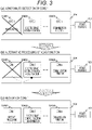
- FIGS. 3 (a) to 3(c) illustrate a procedure until the core restarts in a case where a failure of the core 1 has been detected in the multi-core microcomputer.
- FIG. 3 (a) is a block diagram of the core 1 including an abnormality detected.
- FIG. 3(b) is a block diagram of alternative processing being performed to the ADAS function that has been performed by the core 1, by the core 2, based on PTL 1.
- FIG. 3(c) is a block diagram of only the core 1 restarting, based on PTL 2.
- using the multi-core processor can continue an operation with the function of the entire system not being suspended, and can restore the original state.
- the core 2 performs the ADAS function of the core 1 so that the throughput of the core 2 considerably increases. Accordingly, when the abnormality is detected in the core, the core 1 preferably restarts at high speed as much as possible so as to be restored in the original state. However, restart processing of the core has not been considered in the conventional techniques.
- an object of the present invention is to provide a vehicle control device capable of, when an abnormality is detected in one or more processor cores, shortening time necessary until application software is re-executed since a restart of the core including the abnormality detected.
- US 2010/138693 A1 discloses a vehicle control device according to the preamble of claim 1.
- the time necessary until the application software is executed since the restart of the core can shorten.
- FIG. 1 is a block diagram of a system configuration of a vehicle control device according to the one embodiment of the present invention.
- the vehicle control device 1 includes a diagnostic technique 101, a diagnostic process method change unit 102, a power source IC 103, a multi-core processor 104, a storage area 105, and a diagnostic process log 106.
- the multi-core processor 104 includes a plurality of cores 10401, 10402, and 10403.
- the diagnostic technique 101 includes an all-core-start diagnostic technique 10101 being a diagnostic technique used in starting all the cores and a partial-core-restart diagnostic technique 10102 being a diagnostic technique used in restarting a part of the plurality of processor cores.
- the diagnostic process method change unit 102 selects the all-core-start diagnostic technique 10101 when all the cores start and selects the partial-core-restart diagnostic technique 10102 when the part of the plurality of processor cores restarts. Accordingly, time necessary until application software is executed since the restart of the part of the plurality of processor cores, shortens.
- FIG. 4 is a flow chart of a typical example until the application is executed since a start of the microcomputer. Processing starts at step S1020101.
- the microcomputer starts at step S1020102.
- a built-in self-test (BIST) is performed at step S1020103.
- Diagnosis with software is performed at step S1020104.
- the application is executed at step S1020105 and then the processing finishes at step S1020106.
- the BIST built in a circuit (hardware) is performed and then the diagnosis with the software is performed.
- the software diagnosis described at step S1020104 corresponds to, for example, RAM diagnosis on the storage area 105 using the software. More specifically, the diagnosis writes a fixed value into the storage area 105, and determines whether a result read after the writing is equivalent to the initial fixed value. Accordingly, the diagnosis of whether the storage area 105 normally operates, can be performed.
- examples of the software diagnosis include ROM diagnosis using a checksum and diagnosis on an error check and correct (ECC) function by fault injection.
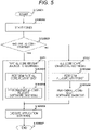
- FIG. 5 is a flow chart of a specific example until the application is executed since a start of the processor cores in the proposed technique, and processing starts at step S1020201.
- the core starts at step S1020202. It is determined whether only a partial processor core has started, at step S1020203. When Yes is acquired, namely, only the partial processor core has started, the processing proceeds to step S1020204 and then the partial-core-restart diagnostic technique 10101 is performed.
- a partial-core-start BIST is performed at step S1020204.
- Partial-core-restart software diagnosis is performed at step S1020205.
- the application software is executed at step S1020206 and the processing finishes at step S1020207.
- step S1020208 when No is acquired at step S1020203, namely, all the processor cores have started, the processing proceeds to step S1020208 and the all-core-start diagnostic technique 10102 is performed.
- An all-core-start BIST is performed at step S1020208.
- All-core-start software diagnosis is performed at step S1020209.
- the application software is executed at step S1020206, and the processing finishes at step S1020207.
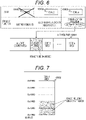
- FIG. 6 illustrates a specific example of the software diagnosis in restarting the part of the plurality of processor cores when the proposed technique has been used.
- FIG. 6 illustrates a state where an abnormality has been detected in the core 1 and the partial-core-restart diagnostic technique 10101 has been performed.
- the core n previously performs the software diagnosis and a core 1 storage area being a range to be diagnosed is diagnosed during the core 1 including the abnormality detected, being performed with the BIST, so that time until the core 1 executes the application software can shorten.
- FIG. 7 illustrates progress management when the software diagnosis is performed to a storage area 10502.
- a method of managing the progress of the software diagnosis storing and managing an address value in a range including the diagnosis finished, can resume the software diagnosis from the initial position even when work is changed during the diagnosis.
- FIG. 8 illustrates software diagnosis progress of a storage area 10503 when the plurality of cores cooperates with each other.
- diagnosis when diagnosis is performed with two cores, one core starts the diagnosis from a lower address value and the other core starts the diagnosis from a higher address value so that time necessary for the diagnosis can further shorten.
Description
- The present invention relates to a vehicle control device that controls a system with a multi-core processor, the system including necessary functions over a wide range and being a large-scale system including a plurality of pieces of hardware and a plurality of pieces of software combined, in transport machinery, such as a motor vehicle, a railway, or an elevator.
- A built-in control device that controls an object to be controlled with so-called built-in software, is used in a motor vehicle, an elevator, or construction machinery. The built-in software is advantageously capable of achieving flexible and advanced control in comparison to a conventional method with a mechanical mechanism or an electric circuit.
- Electronic control unit (ECU) integration including functions that have been conventionally, individually mounted on different ECUs, aggregated on one ECU, has been progressively developed in order to reduce an in- vehicle space and manufacturing costs for such a built-in control device, for example, a vehicle control device. During the progress of the ECU integration, a multi-core processor has been already applied to the vehicle control device because of the plurality of functions required to be processed on the same ECU.
- The multi-core processor is capable of performing different pieces of processing in parallel with a plurality of cores and additionally is, when one or more of the processor cores fails, capable of performing alternative processing to application software allocated to said one or more processor cores, with another core. Accordingly, it has been known that redundancy of the system can be achieved, and for example,
PTL 1 describes the redundancy. - When the failure of one or more processor cores in the multi-core processor is detected, only the core(s) including the failure detected restart so that the failed core(s) can be restored with the function of the entire system not being suspended. As a technique of achieving the above, a technique of dynamically changing operation and non-operation for each core in the multi-core processor, has been known, and, for example,
PTL 2 describes the technique. - However, the throughput of the entire multi-core processor has an upper limit so that all initial application software is difficult to execute during the restart of said one or more processor cores. Accordingly, the core including the failure detected restarts as soon as possible and the allocated application software is executed, preferably.
-
- PTL 1:
JP 2007-154050 A - PTL 2:
JP 2006-260568 A -
FIG. 2 illustrates an example of an in-vehicle function allocated to each core in a multi-core microcomputer. Acore 1 performs an advanced driver assistance systems (ADAS) function, and acore 2 and a core n perform an electric brake system and a communication function, respectively, inFIG. 2 . In this manner, integration of ECUs is performed with the multi-core processor so that the functions that have been conventionally processed by the individual ECUs, can be processed by one ECU. -
FIGS. 3 (a) to 3(c) illustrate a procedure until the core restarts in a case where a failure of thecore 1 has been detected in the multi-core microcomputer.FIG. 3 (a) is a block diagram of thecore 1 including an abnormality detected.FIG. 3(b) is a block diagram of alternative processing being performed to the ADAS function that has been performed by thecore 1, by thecore 2, based onPTL 1.FIG. 3(c) is a block diagram of only thecore 1 restarting, based onPTL 2. - In this manner, even when the abnormality is detected in one or more processor cores, using the multi-core processor can continue an operation with the function of the entire system not being suspended, and can restore the original state.
- In
FIGS. 3(a), 3(b), and 3(c) , thecore 2 performs the ADAS function of thecore 1 so that the throughput of thecore 2 considerably increases. Accordingly, when the abnormality is detected in the core, thecore 1 preferably restarts at high speed as much as possible so as to be restored in the original state. However, restart processing of the core has not been considered in the conventional techniques. - As described above, an object of the present invention is to provide a vehicle control device capable of, when an abnormality is detected in one or more processor cores, shortening time necessary until application software is re-executed since a restart of the core including the abnormality detected.
-
US 2010/138693 A1 discloses a vehicle control device according to the preamble ofclaim 1. - The invention is set out in the appended set of claims.
- According to the present invention, when only part of the plurality of processor cores restarts, the time necessary until the application software is executed since the restart of the core, can shorten.
-
- [
FIG. 1] FIG. 1 is a block diagram of a system configuration of a vehicle control device according to one embodiment of the present invention. - [
FIG. 2] FIG. 2 is a block diagram of specific exemplary parallel processing of functions with a multi-core microcomputer. - [
FIGS. 3 (a) to 3(c)] FIGS. 3 (a) to 3(c) are block diagrams illustrating a flow of specific processing until a core restarts since an abnormality has been detected in the multi-core microcomputer in a case where a conventional technique has been used. - [
FIG. 4] FIG. 4 is a flow chart of a typical example until application software is executed since a start of the microcomputer. - [
FIG. 5] FIG. 5 is a flow chart of a specific example until the application is executed since a start of processor cores, in a proposed technique. - [
FIG. 6] FIG. 6 is a block diagram of a specific example of software diagnosis when a part of the plurality of processor cores restarts, in the proposed technique. - [
FIG. 7] FIG. 7 is a block diagram of a specific example of software diagnosis progress in a storage area in the proposed technique. - [
FIG. 8] FIG. 8 is a block diagram of a specific example of software diagnosis progress in a storage area when a plurality of cores cooperates with each other in the proposed technique. - One embodiment of the present invention will be described below with reference to the drawings.
-
FIG. 1 is a block diagram of a system configuration of a vehicle control device according to the one embodiment of the present invention. Thevehicle control device 1 includes adiagnostic technique 101, a diagnostic processmethod change unit 102, a power source IC 103, amulti-core processor 104, astorage area 105, and adiagnostic process log 106. - Here, the
multi-core processor 104 includes a plurality ofcores - Here, the
diagnostic technique 101 includes an all-core-startdiagnostic technique 10101 being a diagnostic technique used in starting all the cores and a partial-core-restartdiagnostic technique 10102 being a diagnostic technique used in restarting a part of the plurality of processor cores. In starting the processor cores, the diagnostic processmethod change unit 102 selects the all-core-startdiagnostic technique 10101 when all the cores start and selects the partial-core-restartdiagnostic technique 10102 when the part of the plurality of processor cores restarts. Accordingly, time necessary until application software is executed since the restart of the part of the plurality of processor cores, shortens. -
FIG. 4 is a flow chart of a typical example until the application is executed since a start of the microcomputer. Processing starts at step S1020101. The microcomputer starts at step S1020102. A built-in self-test (BIST) is performed at step S1020103. Diagnosis with software is performed at step S1020104. The application is executed at step S1020105 and then the processing finishes at step S1020106. - As illustrated in
FIG. 4 , typically when the microcomputer starts, the BIST built in a circuit (hardware) is performed and then the diagnosis with the software is performed. - Here, the software diagnosis described at step S1020104 corresponds to, for example, RAM diagnosis on the
storage area 105 using the software. More specifically, the diagnosis writes a fixed value into thestorage area 105, and determines whether a result read after the writing is equivalent to the initial fixed value. Accordingly, the diagnosis of whether thestorage area 105 normally operates, can be performed. In addition, examples of the software diagnosis include ROM diagnosis using a checksum and diagnosis on an error check and correct (ECC) function by fault injection. -
FIG. 5 is a flow chart of a specific example until the application is executed since a start of the processor cores in the proposed technique, and processing starts at step S1020201. The core starts at step S1020202. It is determined whether only a partial processor core has started, at step S1020203. When Yes is acquired, namely, only the partial processor core has started, the processing proceeds to step S1020204 and then the partial-core-restartdiagnostic technique 10101 is performed. A partial-core-start BIST is performed at step S1020204. Partial-core-restart software diagnosis is performed at step S1020205. The application software is executed at step S1020206 and the processing finishes at step S1020207. Meanwhile, when No is acquired at step S1020203, namely, all the processor cores have started, the processing proceeds to step S1020208 and the all-core-startdiagnostic technique 10102 is performed. An all-core-start BIST is performed at step S1020208. All-core-start software diagnosis is performed at step S1020209. The application software is executed at step S1020206, and the processing finishes at step S1020207. -
FIG. 6 illustrates a specific example of the software diagnosis in restarting the part of the plurality of processor cores when the proposed technique has been used.FIG. 6 illustrates a state where an abnormality has been detected in thecore 1 and the partial-core-restartdiagnostic technique 10101 has been performed. According to the invention, the core n previously performs the software diagnosis and acore 1 storage area being a range to be diagnosed is diagnosed during thecore 1 including the abnormality detected, being performed with the BIST, so that time until thecore 1 executes the application software can shorten. -
FIG. 7 illustrates progress management when the software diagnosis is performed to astorage area 10502. As illustrated inFIG. 7 , as a method of managing the progress of the software diagnosis, storing and managing an address value in a range including the diagnosis finished, can resume the software diagnosis from the initial position even when work is changed during the diagnosis. -
FIG. 8 illustrates software diagnosis progress of astorage area 10503 when the plurality of cores cooperates with each other. As illustrated inFIG. 8 , according to the invention, when diagnosis is performed with two cores, one core starts the diagnosis from a lower address value and the other core starts the diagnosis from a higher address value so that time necessary for the diagnosis can further shorten. -
- 1 vehicle control device
- 101 diagnostic means
- 10101 all-core-start diagnostic means
- 10102 partial-restart diagnostic means
- 102 diagnostic process method change unit
- 103 power source IC
- 104 multi-core processor
- 10401, 10402, 10403 processor core
- 105, 10501, 10502, 10503 storage area
- 106 diagnostic process log
Claims (7)
- A vehicle control device (1) comprising:a multi-core processor (104) with a plurality of cores (10401, 10402, 10403);a storage area (105); anda diagnostic means (101) configured to perform diagnostic processing including a built-in self-test as a hardware diagnosis when starting the plurality of processor cores (10401, 10402, 10403) and a diagnosis of whether the storage area (105) operates normally following the hardware diagnosis,characterized bya diagnostic process information change processing means (102) configured to change a method (10101, 10102) of performing the diagnostic processing between when all the processor cores (10401, 10402, 10403) start and when part of the plurality of processor cores (10401, 10402, 10403) restart,wherein in the method (10102) for restarting said one or more processor cores, the one or more restarting processor cores (10401) detect an abnormality while the built-in self-test is being executed, another processor core (10403) previously executes the diagnosis and diagnoses the storage area (105) for the one or more restarting processor cores (10401) during the one or more restarting processor cores (10401) are being performed with the built-in self-test,wherein when the diagnosis is performed with two processor cores, one processor core starts the diagnosis from a lower address value of the storage area (105) and the other processor core starts the diagnosis from a higher address value of the storage area (105).
- The vehicle control device (1) according to claim 1,
wherein the diagnosis of the storage area (105) includes a RAM diagnosis and preferably also a ROM diagnosis using a checksum and/or a diagnosis on an error check and correct function by fault injection. - The vehicle control device (1) according to claim 2,
wherein, when the another processor core (10403) performs the diagnosis to the storage area corresponding to the restarting one or more processor cores (10401), progress of the diagnosis is monitored. - The vehicle control device (1) according to claim 3,
wherein the restarting one or more processor cores (10401) refers to the progress of the diagnosis of its storage area by the another processor core (10403) when a built-in self-test as a hardware diagnosis has been completed and starts its diagnosis of the storage area corresponding to the restarting processor core (10401). - The vehicle control device (1) according to any of claims 1 to 4,
wherein an access right to the storage area of the processor core is changed in performing the diagnosis of the storage area (105). - The vehicle control device (1) according to any of claims 1 to 5, comprising:
a dedicated processor core configured to perform the diagnosis of the storage area (105). - The vehicle control device (1) according to claims 1 to 6,
wherein a result of the diagnosis of the storage area (105) is output as a diagnostic log (106).
Applications Claiming Priority (2)
| Application Number | Priority Date | Filing Date | Title |
|---|---|---|---|
| JP2015009051A JP6393628B2 (en) | 2015-01-21 | 2015-01-21 | Vehicle control device |
| PCT/JP2016/050604 WO2016117402A1 (en) | 2015-01-21 | 2016-01-12 | Vehicle control device |
Publications (3)
| Publication Number | Publication Date |
|---|---|
| EP3249534A1 EP3249534A1 (en) | 2017-11-29 |
| EP3249534A4 EP3249534A4 (en) | 2018-09-26 |
| EP3249534B1 true EP3249534B1 (en) | 2022-06-22 |
Family
ID=56416949
Family Applications (1)
| Application Number | Title | Priority Date | Filing Date |
|---|---|---|---|
| EP16740009.2A Active EP3249534B1 (en) | 2015-01-21 | 2016-01-12 | Vehicle control device |
Country Status (5)
| Country | Link |
|---|---|
| US (1) | US10394675B2 (en) |
| EP (1) | EP3249534B1 (en) |
| JP (1) | JP6393628B2 (en) |
| CN (1) | CN107077407B (en) |
| WO (1) | WO2016117402A1 (en) |
Families Citing this family (9)
| Publication number | Priority date | Publication date | Assignee | Title |
|---|---|---|---|---|
| JP7017871B2 (en) * | 2017-07-06 | 2022-02-09 | 日立Astemo株式会社 | Vehicle control simulation device |
| KR102131982B1 (en) * | 2018-05-31 | 2020-07-08 | 현대오트론 주식회사 | Multi core system and software diagnostic system for vehicle and operating method thereof |
| JP7384554B2 (en) * | 2018-08-30 | 2023-11-21 | トヨタ自動車株式会社 | Brake ECU, system, control method and vehicle |
| CN114007906B (en) * | 2019-07-12 | 2024-03-15 | 日立安斯泰莫株式会社 | Safety processing device |
| US11030128B2 (en) * | 2019-08-05 | 2021-06-08 | Cypress Semiconductor Corporation | Multi-ported nonvolatile memory device with bank allocation and related systems and methods |
| CN113067528B (en) * | 2019-12-31 | 2023-01-06 | 比亚迪股份有限公司 | Motor control system and vehicle with same |
| DE102020205146A1 (en) * | 2020-04-23 | 2021-10-28 | Robert Bosch Gesellschaft mit beschränkter Haftung | Device and method for controlling a technical system |
| JP7410804B2 (en) | 2020-06-11 | 2024-01-10 | 日立Astemo株式会社 | Vehicle control system, vehicle control method, and vehicle control device |
| JP6991294B1 (en) | 2020-10-09 | 2022-01-12 | 三菱電機株式会社 | Control device |
Family Cites Families (14)
| Publication number | Priority date | Publication date | Assignee | Title |
|---|---|---|---|---|
| JP3293125B2 (en) | 1998-07-24 | 2002-06-17 | 日本電気株式会社 | Initial setting and diagnosis method for on-chip multiprocessor system |
| JP3388344B2 (en) * | 1998-12-25 | 2003-03-17 | 日本電気エンジニアリング株式会社 | Interconnection network, interconnection network self-diagnosis system, and interconnection network self-diagnosis method |
| JP2001175494A (en) * | 1999-12-14 | 2001-06-29 | Nec Corp | System and method for doubly diagnosing normality of arithmetic processing of microprocessor |
| JP2002366536A (en) * | 2002-04-18 | 2002-12-20 | Fujitsu Ltd | Processor system |
| EP1496435A1 (en) * | 2003-07-11 | 2005-01-12 | Yogitech Spa | Dependable microcontroller, method for designing a dependable microcontroller and computer program product therefor |
| US20060212677A1 (en) | 2005-03-15 | 2006-09-21 | Intel Corporation | Multicore processor having active and inactive execution cores |
| JP2007154050A (en) | 2005-12-06 | 2007-06-21 | Hyogo Prefecture | Method for treating surface of plastic to impart functionality |
| JP2008123031A (en) * | 2006-11-08 | 2008-05-29 | Toyota Motor Corp | Shared memory management device and multiprocessor system equipped with the same device |
| US20080235454A1 (en) * | 2007-03-22 | 2008-09-25 | Ibm Corporation | Method and Apparatus for Repairing a Processor Core During Run Time in a Multi-Processor Data Processing System |
| JP4709268B2 (en) * | 2008-11-28 | 2011-06-22 | 日立オートモティブシステムズ株式会社 | Multi-core system for vehicle control or control device for internal combustion engine |
| JP5311473B2 (en) * | 2009-01-23 | 2013-10-09 | エヌイーシーコンピュータテクノ株式会社 | Computer system and re-installation method of CPU |
| CN110083494B (en) * | 2011-12-30 | 2023-07-25 | 英特尔公司 | Method and apparatus for managing hardware errors in a multi-core environment |
| US9525700B1 (en) * | 2013-01-25 | 2016-12-20 | REMTCS Inc. | System and method for detecting malicious activity and harmful hardware/software modifications to a vehicle |
| JP2014191389A (en) * | 2013-03-26 | 2014-10-06 | Nec Corp | Information processor, memory inspection/load method and boot program |
-
2015
- 2015-01-21 JP JP2015009051A patent/JP6393628B2/en active Active
-
2016
- 2016-01-12 US US15/541,603 patent/US10394675B2/en active Active
- 2016-01-12 EP EP16740009.2A patent/EP3249534B1/en active Active
- 2016-01-12 CN CN201680003130.8A patent/CN107077407B/en active Active
- 2016-01-12 WO PCT/JP2016/050604 patent/WO2016117402A1/en active Application Filing
Also Published As
| Publication number | Publication date |
|---|---|
| EP3249534A1 (en) | 2017-11-29 |
| WO2016117402A1 (en) | 2016-07-28 |
| US20170357560A1 (en) | 2017-12-14 |
| US10394675B2 (en) | 2019-08-27 |
| JP2016134049A (en) | 2016-07-25 |
| CN107077407B (en) | 2020-02-21 |
| EP3249534A4 (en) | 2018-09-26 |
| JP6393628B2 (en) | 2018-09-19 |
| CN107077407A (en) | 2017-08-18 |
Similar Documents
| Publication | Publication Date | Title |
|---|---|---|
| EP3249534B1 (en) | Vehicle control device | |
| JP6189004B1 (en) | Shared backup unit and control system | |
| US10576990B2 (en) | Method and device for handling safety critical errors | |
| EP3330857B1 (en) | Vehicle control device | |
| CN105501227B (en) | Road emergency activation | |
| CN108146250B (en) | Automobile torque safety control method based on multi-core CPU | |
| US20160232070A1 (en) | Method for operating a data processing unit of a driver assistance system and data processing unit | |
| JP2012181564A (en) | Self-diagnosis circuit and self-diagnosis method | |
| JP2001175497A (en) | Logic diagnosing method | |
| JP2015184796A (en) | Electronic control unit and memory diagnosis method | |
| US20130055017A1 (en) | Device and method for restoring information in a main storage unit | |
| JP6183251B2 (en) | Electronic control unit | |
| US11385977B2 (en) | Reconfiguration control device | |
| JP5978873B2 (en) | Electronic control unit | |
| US10514970B2 (en) | Method of ensuring operation of calculator | |
| JP6168847B2 (en) | Multi-core system | |
| US20170031703A1 (en) | Method and device for updating a virtual machine operated on a physical machine under a hypervisor | |
| JP7000456B2 (en) | Error correction in redundant processing system | |
| JP6275098B2 (en) | Control device and register failure recovery method | |
| WO2012165396A1 (en) | Electronic control system | |
| JP2020046979A (en) | In-vehicle electronic control device | |
| CN106445658B (en) | Method and apparatus for running transformed guest systems under a hypervisor | |
| WO2019106830A1 (en) | Distribution control device | |
| JP2018161927A (en) | Automobile electronic control device | |
| KR20100093668A (en) | Method for storing diagnosis data in electric brake system |
Legal Events
| Date | Code | Title | Description |
|---|---|---|---|
| STAA | Information on the status of an ep patent application or granted ep patent |
Free format text: STATUS: THE INTERNATIONAL PUBLICATION HAS BEEN MADE |
|
| PUAI | Public reference made under article 153(3) epc to a published international application that has entered the european phase |
Free format text: ORIGINAL CODE: 0009012 |
|
| STAA | Information on the status of an ep patent application or granted ep patent |
Free format text: STATUS: REQUEST FOR EXAMINATION WAS MADE |
|
| 17P | Request for examination filed |
Effective date: 20170821 |
|
| AK | Designated contracting states |
Kind code of ref document: A1 Designated state(s): AL AT BE BG CH CY CZ DE DK EE ES FI FR GB GR HR HU IE IS IT LI LT LU LV MC MK MT NL NO PL PT RO RS SE SI SK SM TR |
|
| AX | Request for extension of the european patent |
Extension state: BA ME |
|
| DAV | Request for validation of the european patent (deleted) | ||
| DAX | Request for extension of the european patent (deleted) | ||
| A4 | Supplementary search report drawn up and despatched |
Effective date: 20180823 |
|
| RIC1 | Information provided on ipc code assigned before grant |
Ipc: G06F 9/445 20060101ALI20180817BHEP Ipc: G06F 9/4401 20180101ALI20180817BHEP Ipc: G06F 11/07 20060101ALI20180817BHEP Ipc: G06F 11/14 20060101ALI20180817BHEP Ipc: G06F 11/22 20060101AFI20180817BHEP |
|
| STAA | Information on the status of an ep patent application or granted ep patent |
Free format text: STATUS: EXAMINATION IS IN PROGRESS |
|
| 17Q | First examination report despatched |
Effective date: 20190614 |
|
| STAA | Information on the status of an ep patent application or granted ep patent |
Free format text: STATUS: EXAMINATION IS IN PROGRESS |
|
| RAP3 | Party data changed (applicant data changed or rights of an application transferred) |
Owner name: HITACHI ASTEMO, LTD. |
|
| STAA | Information on the status of an ep patent application or granted ep patent |
Free format text: STATUS: EXAMINATION IS IN PROGRESS |
|
| GRAP | Despatch of communication of intention to grant a patent |
Free format text: ORIGINAL CODE: EPIDOSNIGR1 |
|
| STAA | Information on the status of an ep patent application or granted ep patent |
Free format text: STATUS: GRANT OF PATENT IS INTENDED |
|
| INTG | Intention to grant announced |
Effective date: 20220401 |
|
| GRAS | Grant fee paid |
Free format text: ORIGINAL CODE: EPIDOSNIGR3 |
|
| GRAA | (expected) grant |
Free format text: ORIGINAL CODE: 0009210 |
|
| STAA | Information on the status of an ep patent application or granted ep patent |
Free format text: STATUS: THE PATENT HAS BEEN GRANTED |
|
| AK | Designated contracting states |
Kind code of ref document: B1 Designated state(s): AL AT BE BG CH CY CZ DE DK EE ES FI FR GB GR HR HU IE IS IT LI LT LU LV MC MK MT NL NO PL PT RO RS SE SI SK SM TR |
|
| REG | Reference to a national code |
Ref country code: GB Ref legal event code: FG4D |
|
| REG | Reference to a national code |
Ref country code: CH Ref legal event code: EP |
|
| REG | Reference to a national code |
Ref country code: DE Ref legal event code: R096 Ref document number: 602016072987 Country of ref document: DE |
|
| REG | Reference to a national code |
Ref country code: AT Ref legal event code: REF Ref document number: 1500224 Country of ref document: AT Kind code of ref document: T Effective date: 20220715 |
|
| REG | Reference to a national code |
Ref country code: IE Ref legal event code: FG4D |
|
| REG | Reference to a national code |
Ref country code: LT Ref legal event code: MG9D |
|
| REG | Reference to a national code |
Ref country code: NL Ref legal event code: MP Effective date: 20220622 |
|
| PG25 | Lapsed in a contracting state [announced via postgrant information from national office to epo] |
Ref country code: SE Free format text: LAPSE BECAUSE OF FAILURE TO SUBMIT A TRANSLATION OF THE DESCRIPTION OR TO PAY THE FEE WITHIN THE PRESCRIBED TIME-LIMIT Effective date: 20220622 Ref country code: NO Free format text: LAPSE BECAUSE OF FAILURE TO SUBMIT A TRANSLATION OF THE DESCRIPTION OR TO PAY THE FEE WITHIN THE PRESCRIBED TIME-LIMIT Effective date: 20220922 Ref country code: LT Free format text: LAPSE BECAUSE OF FAILURE TO SUBMIT A TRANSLATION OF THE DESCRIPTION OR TO PAY THE FEE WITHIN THE PRESCRIBED TIME-LIMIT Effective date: 20220622 Ref country code: HR Free format text: LAPSE BECAUSE OF FAILURE TO SUBMIT A TRANSLATION OF THE DESCRIPTION OR TO PAY THE FEE WITHIN THE PRESCRIBED TIME-LIMIT Effective date: 20220622 Ref country code: GR Free format text: LAPSE BECAUSE OF FAILURE TO SUBMIT A TRANSLATION OF THE DESCRIPTION OR TO PAY THE FEE WITHIN THE PRESCRIBED TIME-LIMIT Effective date: 20220923 Ref country code: FI Free format text: LAPSE BECAUSE OF FAILURE TO SUBMIT A TRANSLATION OF THE DESCRIPTION OR TO PAY THE FEE WITHIN THE PRESCRIBED TIME-LIMIT Effective date: 20220622 Ref country code: BG Free format text: LAPSE BECAUSE OF FAILURE TO SUBMIT A TRANSLATION OF THE DESCRIPTION OR TO PAY THE FEE WITHIN THE PRESCRIBED TIME-LIMIT Effective date: 20220922 |
|
| REG | Reference to a national code |
Ref country code: AT Ref legal event code: MK05 Ref document number: 1500224 Country of ref document: AT Kind code of ref document: T Effective date: 20220622 |
|
| PG25 | Lapsed in a contracting state [announced via postgrant information from national office to epo] |
Ref country code: RS Free format text: LAPSE BECAUSE OF FAILURE TO SUBMIT A TRANSLATION OF THE DESCRIPTION OR TO PAY THE FEE WITHIN THE PRESCRIBED TIME-LIMIT Effective date: 20220622 Ref country code: LV Free format text: LAPSE BECAUSE OF FAILURE TO SUBMIT A TRANSLATION OF THE DESCRIPTION OR TO PAY THE FEE WITHIN THE PRESCRIBED TIME-LIMIT Effective date: 20220622 |
|
| PG25 | Lapsed in a contracting state [announced via postgrant information from national office to epo] |
Ref country code: NL Free format text: LAPSE BECAUSE OF FAILURE TO SUBMIT A TRANSLATION OF THE DESCRIPTION OR TO PAY THE FEE WITHIN THE PRESCRIBED TIME-LIMIT Effective date: 20220622 |
|
| PG25 | Lapsed in a contracting state [announced via postgrant information from national office to epo] |
Ref country code: SM Free format text: LAPSE BECAUSE OF FAILURE TO SUBMIT A TRANSLATION OF THE DESCRIPTION OR TO PAY THE FEE WITHIN THE PRESCRIBED TIME-LIMIT Effective date: 20220622 Ref country code: SK Free format text: LAPSE BECAUSE OF FAILURE TO SUBMIT A TRANSLATION OF THE DESCRIPTION OR TO PAY THE FEE WITHIN THE PRESCRIBED TIME-LIMIT Effective date: 20220622 Ref country code: RO Free format text: LAPSE BECAUSE OF FAILURE TO SUBMIT A TRANSLATION OF THE DESCRIPTION OR TO PAY THE FEE WITHIN THE PRESCRIBED TIME-LIMIT Effective date: 20220622 Ref country code: PT Free format text: LAPSE BECAUSE OF FAILURE TO SUBMIT A TRANSLATION OF THE DESCRIPTION OR TO PAY THE FEE WITHIN THE PRESCRIBED TIME-LIMIT Effective date: 20221024 Ref country code: ES Free format text: LAPSE BECAUSE OF FAILURE TO SUBMIT A TRANSLATION OF THE DESCRIPTION OR TO PAY THE FEE WITHIN THE PRESCRIBED TIME-LIMIT Effective date: 20220622 Ref country code: EE Free format text: LAPSE BECAUSE OF FAILURE TO SUBMIT A TRANSLATION OF THE DESCRIPTION OR TO PAY THE FEE WITHIN THE PRESCRIBED TIME-LIMIT Effective date: 20220622 Ref country code: CZ Free format text: LAPSE BECAUSE OF FAILURE TO SUBMIT A TRANSLATION OF THE DESCRIPTION OR TO PAY THE FEE WITHIN THE PRESCRIBED TIME-LIMIT Effective date: 20220622 Ref country code: AT Free format text: LAPSE BECAUSE OF FAILURE TO SUBMIT A TRANSLATION OF THE DESCRIPTION OR TO PAY THE FEE WITHIN THE PRESCRIBED TIME-LIMIT Effective date: 20220622 |
|
| PG25 | Lapsed in a contracting state [announced via postgrant information from national office to epo] |
Ref country code: PL Free format text: LAPSE BECAUSE OF FAILURE TO SUBMIT A TRANSLATION OF THE DESCRIPTION OR TO PAY THE FEE WITHIN THE PRESCRIBED TIME-LIMIT Effective date: 20220622 Ref country code: IS Free format text: LAPSE BECAUSE OF FAILURE TO SUBMIT A TRANSLATION OF THE DESCRIPTION OR TO PAY THE FEE WITHIN THE PRESCRIBED TIME-LIMIT Effective date: 20221022 |
|
| REG | Reference to a national code |
Ref country code: DE Ref legal event code: R097 Ref document number: 602016072987 Country of ref document: DE |
|
| PG25 | Lapsed in a contracting state [announced via postgrant information from national office to epo] |
Ref country code: AL Free format text: LAPSE BECAUSE OF FAILURE TO SUBMIT A TRANSLATION OF THE DESCRIPTION OR TO PAY THE FEE WITHIN THE PRESCRIBED TIME-LIMIT Effective date: 20220622 |
|
| PG25 | Lapsed in a contracting state [announced via postgrant information from national office to epo] |
Ref country code: DK Free format text: LAPSE BECAUSE OF FAILURE TO SUBMIT A TRANSLATION OF THE DESCRIPTION OR TO PAY THE FEE WITHIN THE PRESCRIBED TIME-LIMIT Effective date: 20220622 |
|
| PLBE | No opposition filed within time limit |
Free format text: ORIGINAL CODE: 0009261 |
|
| STAA | Information on the status of an ep patent application or granted ep patent |
Free format text: STATUS: NO OPPOSITION FILED WITHIN TIME LIMIT |
|
| 26N | No opposition filed |
Effective date: 20230323 |
|
| PGFP | Annual fee paid to national office [announced via postgrant information from national office to epo] |
Ref country code: DE Payment date: 20230328 Year of fee payment: 8 |
|
| PG25 | Lapsed in a contracting state [announced via postgrant information from national office to epo] |
Ref country code: SI Free format text: LAPSE BECAUSE OF FAILURE TO SUBMIT A TRANSLATION OF THE DESCRIPTION OR TO PAY THE FEE WITHIN THE PRESCRIBED TIME-LIMIT Effective date: 20220622 |
|
| REG | Reference to a national code |
Ref country code: CH Ref legal event code: PL |
|
| GBPC | Gb: european patent ceased through non-payment of renewal fee |
Effective date: 20230112 |
|
| PG25 | Lapsed in a contracting state [announced via postgrant information from national office to epo] |
Ref country code: LU Free format text: LAPSE BECAUSE OF NON-PAYMENT OF DUE FEES Effective date: 20230112 |
|
| REG | Reference to a national code |
Ref country code: BE Ref legal event code: MM Effective date: 20230131 |
|
| PG25 | Lapsed in a contracting state [announced via postgrant information from national office to epo] |
Ref country code: LI Free format text: LAPSE BECAUSE OF NON-PAYMENT OF DUE FEES Effective date: 20230131 Ref country code: GB Free format text: LAPSE BECAUSE OF NON-PAYMENT OF DUE FEES Effective date: 20230112 Ref country code: CH Free format text: LAPSE BECAUSE OF NON-PAYMENT OF DUE FEES Effective date: 20230131 |
|
| PG25 | Lapsed in a contracting state [announced via postgrant information from national office to epo] |
Ref country code: FR Free format text: LAPSE BECAUSE OF NON-PAYMENT OF DUE FEES Effective date: 20230131 Ref country code: BE Free format text: LAPSE BECAUSE OF NON-PAYMENT OF DUE FEES Effective date: 20230131 |
|
| PG25 | Lapsed in a contracting state [announced via postgrant information from national office to epo] |
Ref country code: IT Free format text: LAPSE BECAUSE OF FAILURE TO SUBMIT A TRANSLATION OF THE DESCRIPTION OR TO PAY THE FEE WITHIN THE PRESCRIBED TIME-LIMIT Effective date: 20220622 Ref country code: IE Free format text: LAPSE BECAUSE OF NON-PAYMENT OF DUE FEES Effective date: 20230112 |