JP4709268B2 - Multi-core system for vehicle control or control device for internal combustion engine - Google Patents
Multi-core system for vehicle control or control device for internal combustion engine Download PDFInfo
- Publication number
- JP4709268B2 JP4709268B2 JP2008303369A JP2008303369A JP4709268B2 JP 4709268 B2 JP4709268 B2 JP 4709268B2 JP 2008303369 A JP2008303369 A JP 2008303369A JP 2008303369 A JP2008303369 A JP 2008303369A JP 4709268 B2 JP4709268 B2 JP 4709268B2
- Authority
- JP
- Japan
- Prior art keywords
- core
- cores
- failure
- arithmetic processing
- vehicle control
- Prior art date
- Legal status (The legal status is an assumption and is not a legal conclusion. Google has not performed a legal analysis and makes no representation as to the accuracy of the status listed.)
- Expired - Fee Related
Links
Images


Classifications
-
- G—PHYSICS
- G06—COMPUTING; CALCULATING OR COUNTING
- G06F—ELECTRIC DIGITAL DATA PROCESSING
- G06F11/00—Error detection; Error correction; Monitoring
- G06F11/07—Responding to the occurrence of a fault, e.g. fault tolerance
- G06F11/16—Error detection or correction of the data by redundancy in hardware
- G06F11/18—Error detection or correction of the data by redundancy in hardware using passive fault-masking of the redundant circuits
- G06F11/187—Voting techniques
- G06F11/188—Voting techniques where exact match is not required
-
- G—PHYSICS
- G06—COMPUTING; CALCULATING OR COUNTING
- G06F—ELECTRIC DIGITAL DATA PROCESSING
- G06F11/00—Error detection; Error correction; Monitoring
- G06F11/07—Responding to the occurrence of a fault, e.g. fault tolerance
- G06F11/16—Error detection or correction of the data by redundancy in hardware
- G06F11/1695—Error detection or correction of the data by redundancy in hardware which are operating with time diversity
-
- G—PHYSICS
- G06—COMPUTING; CALCULATING OR COUNTING
- G06F—ELECTRIC DIGITAL DATA PROCESSING
- G06F11/00—Error detection; Error correction; Monitoring
- G06F11/07—Responding to the occurrence of a fault, e.g. fault tolerance
- G06F11/16—Error detection or correction of the data by redundancy in hardware
- G06F11/1629—Error detection by comparing the output of redundant processing systems
- G06F11/1637—Error detection by comparing the output of redundant processing systems using additional compare functionality in one or some but not all of the redundant processing components
-
- G—PHYSICS
- G06—COMPUTING; CALCULATING OR COUNTING
- G06F—ELECTRIC DIGITAL DATA PROCESSING
- G06F11/00—Error detection; Error correction; Monitoring
- G06F11/07—Responding to the occurrence of a fault, e.g. fault tolerance
- G06F11/16—Error detection or correction of the data by redundancy in hardware
- G06F11/1629—Error detection by comparing the output of redundant processing systems
- G06F11/165—Error detection by comparing the output of redundant processing systems with continued operation after detection of the error
-
- G—PHYSICS
- G06—COMPUTING; CALCULATING OR COUNTING
- G06F—ELECTRIC DIGITAL DATA PROCESSING
- G06F11/00—Error detection; Error correction; Monitoring
- G06F11/07—Responding to the occurrence of a fault, e.g. fault tolerance
- G06F11/16—Error detection or correction of the data by redundancy in hardware
- G06F11/18—Error detection or correction of the data by redundancy in hardware using passive fault-masking of the redundant circuits
- G06F11/181—Eliminating the failing redundant component
Landscapes
- Engineering & Computer Science (AREA)
- Theoretical Computer Science (AREA)
- Quality & Reliability (AREA)
- Physics & Mathematics (AREA)
- General Engineering & Computer Science (AREA)
- General Physics & Mathematics (AREA)
- Combined Controls Of Internal Combustion Engines (AREA)
- Hardware Redundancy (AREA)
Abstract
Description
本発明は、車両に搭載された機器を制御する組み込み制御装置に係わり、特に複数のCPUから構成されるマルチコアCPUシステムの故障診断に関する。 The present invention relates to a built-in control device that controls equipment mounted on a vehicle, and more particularly to failure diagnosis of a multi-core CPU system including a plurality of CPUs.
制御機器の信頼性向上や処理速度向上のために、制御コンピュータのCPUを複数のプロセッサで構成したり、複数のCPUコアで構成したマルチコアCPUを用いるケースが増えている。このようなコンピュータにおいては、各プロセッサまたは各コアが故障した場合にはそれを速やかに検出し、当該プロセッサまたはコアを停止させ、制御への影響を防ぐなどの処理が必要となる。例えば特許文献1で開示されたような冗長系システムがよく知られている。特許文献1では、複数の冗長化されたサブシステムの出力したデータを比較し、データが一致している最も信頼度の高いサブシステムからの出力を選択するシステムが示されている。また特許文献2では、複数の出力の多数決比較をして最終的な出力を決定するシステムが示されている。また特許文献3では、特別な診断用のプログラムやデータを用いずに、通常の演算処理を行いながら複数のCPUコアの診断を行う方法が示されている。また特許文献4では、各プロセッサにハードウェア障害を検出するためのテストプログラムを起動させるシステムが示されている。
In order to improve the reliability and processing speed of control devices, the number of cases in which the CPU of a control computer is composed of a plurality of processors or a multi-core CPU composed of a plurality of CPU cores is increasing. In such a computer, when each processor or each core fails, it is necessary to detect it quickly, stop the processor or the core, and prevent the influence on the control. For example, a redundant system as disclosed in
上記のように、データの一致性比較を行うシステムは信頼性向上を目的としており、複数プロセッサまたは複数コアで同一の処理を行い、その処理結果を冗長系システムを構築することが前提となっている。また、特許文献3で提案されている故障診断方法では、通常の演算処理を複数のCPUコアで同様に行い、それぞれの処理結果を比較するため、CPUのリソース消費が増大する課題がある。これらのシステムでさらに処理速度向上を行うためには、プロセッサまたはコアをさらに増やす必要があり、コストおよび搭載容積の増加を招いてしまう。車両用制御装置においては、コストパフォーマンスと搭載性の観点から、これらのシステムを適用することは難しい。なお、この課題に関し、特許文献4では分散処理を行いつつ故障診断用のテストプログラムを各プロセッサで起動するシステムが提案されている。しかしこのテストプログラムは、通常時の演算処理とは異なる演算処理であり、各プロセッサまたは各コアにとって演算負荷となるという課題がある。
As described above, the system for comparing the consistency of data is aimed at improving reliability, and it is assumed that the same processing is performed by a plurality of processors or a plurality of cores, and the processing result is constructed as a redundant system. Yes. Further, in the failure diagnosis method proposed in
本発明の目的とするところは信頼性向上と処理速度向上との両立であり、特別なテストプログラムなどによる冗長な演算処理,CPUリソースの消費を抑制しながらマルチコアCPUシステムを用いる車両用制御装置の複数コアの故障判定を実現することにある。 The object of the present invention is to improve both reliability and processing speed, and to provide a vehicle control device that uses a multi-core CPU system while suppressing redundant arithmetic processing by a special test program or the like and consumption of CPU resources. The purpose is to realize failure determination of multiple cores.
上記課題を解決するため、本発明は、複数のコアを用いて車両に搭載された機器を制御するための車両制御用マルチコアシステムであって、連続的に変化する入力値を取得し、前記機器の制御に必要な出力値を演算する演算処理手段を備え、前記演算処理手段が前記複数のコア中の特定のコアにおいて特定のタイミングで演算処理を行った出力値と、前記特定のコアとは異なる、前記複数のコア中の他のコアにおいて、前記演算処理手段が前記特定のタイミングとは異なるタイミングで演算処理を行った出力値と、の比較を行い、前記特定のコアに故障が生じていると判断するコア故障判断手段を備えることを特徴とする。In order to solve the above-described problem, the present invention provides a multi-core system for vehicle control for controlling a device mounted on a vehicle using a plurality of cores, obtaining a continuously changing input value, An arithmetic processing means for calculating an output value necessary for control of the output value, the output value obtained by the arithmetic processing means performing arithmetic processing at a specific timing in a specific core of the plurality of cores, and the specific core In another core among the plurality of different cores, the arithmetic processing means compares the output value with the arithmetic processing performed at a timing different from the specific timing, and a failure occurs in the specific core. It comprises a core failure judging means for judging that it is present.
本発明によれば、複数のコアで同一処理を実行することを抑制できるため、コアのリソースを有効に利用でき、また特別なテストプログラムが不要なため、演算負荷の少ないマルチコアシステムの故障診断が実現できる。
According to the present invention, it is possible to suppress the execution of the same processing by a plurality of cores, so that core resources can be used effectively, and a special test program is not required. realizable.
以下、発明の実施の形態を説明する。 Embodiments of the invention will be described below.
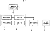
本発明の第1の実施例を図面を用いて説明する。図2はこの発明の実施の形態を示した全体構成図であり、図において6はマイクロコンピュータを備えた制御コントロールユニット(C/U)、7はマイクロコンピュータ(CPU)、8は読み取り専用記憶装置(ROM)、9は読み書き可能記憶装置(RAM)、10は車両、11は車両10に備えられたセンサ、12は車両10に備えられたアクチュエータ、13はセンサ11,アクチュエータ12の信号を送受する入出力装置(I/O)、である。
A first embodiment of the present invention will be described with reference to the drawings. FIG. 2 is an overall configuration diagram showing an embodiment of the present invention, in which 6 is a control control unit (C / U) having a microcomputer, 7 is a microcomputer (CPU), and 8 is a read-only storage device. (ROM), 9 is a readable / writable storage device (RAM), 10 is a vehicle, 11 is a sensor provided in the
C/U6にはセンサ11からの信号が入力される。C/U6は前記入力信号およびROM8に内蔵された制御データを用いて演算を行い、アクチュエータ12へ制御信号を出力する。
A signal from the
例えばC/U6を車載エンジン制御コントロールユニット、車両10をガソリン噴射式内燃機関、センサ11を吸入空気量センサおよびエンジン回転数センサ,アクチュエータ12を燃料噴射弁とすると、CPU7は前記吸入空気量センサおよびエンジン回転数センサからI/O13を通して得た吸入空気量情報およびエンジン回転数情報をROM8に内蔵された制御データと照合して燃料噴射量を算出し、該燃料噴射量に基づいて前記燃料噴射弁の開弁時間を制御する信号をI/O13を通して前記燃料噴射弁に出力し、燃料噴射制御を行うシステムなどが挙げられる。
For example, if C /
ここでCPU7の内部構成を図3に示す。CPU7は2つ以上の中央演算処理装置(コア)で構成されるマルチコアCPUであり、この図ではコアA〜D(14〜17)の4つのコアで構成される例を示している。ここではコアの数が4つの場合の例を示しているが、2つ以上であればいくつであってもよい。コアA〜D(14〜17)はそれぞれがデータバス18と接続されている。データバス18はI/Oポート19,データ読み込みポート20,データ書き込みポート21と接続されており、外部のI/O13,ROM8,RAM9とのデータ入出力を行う。なお、本実施例においては、一つのCPUパッケージ内に複数コアを有するマルチコアCPUを用いたシステムを挙げているが、このマルチコアCPUに代えて、複数のCPUパッケージを有するマルチプロセッサシステムを採用してもよく、本発明においてコアとプロセッサの表記の差異は特別に区別しない。
Here, the internal configuration of the
次に動作について説明する。図4はCPU7のオペレーティングシステム(OS)の動作を示したフローチャートである。CPU7の起動後、ステップ1では、関数Aの処理を各コアに割り当てる処理を行う。ここで関数Aは車両の制御に関わる演算処理手段の一例であり、本発明のマルチコアシステムの故障診断に用いる演算処理手段は、出力結果に一定の連続性が期待できるものであれば何でも良く、例えば前記の燃料噴射量を算出する関数などが挙げられる。なお、ここでいう連続性については後に具体例を用いて説明を行う。次に、ステップ2では、前記関数Aの処理が含まれるタスクの実行を開始する。ステップ3では、タスク処理で判定された故障判定の結果を用いて処理の分岐を行う。正常判定(コア故障なし)の場合はタスク処理を続行し、再びステップ3に戻る。故障判定(コア故障あり)の場合は処理を終了する。
Next, the operation will be described. FIG. 4 is a flowchart showing the operation of the operating system (OS) of the
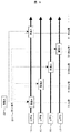
ここでステップ1の割り当て処理について図5を用いて詳細に説明する。図5はコアA〜D(14〜17)のそれぞれコアの処理を時間軸で表している。ここでタスクは例として10ms周期とし、ある時刻Xを起点としてXms後、X+10ms後、X+20ms後、X+30ms後と10msずつ進む様子を示している。関数A22はステップ1の割り当て処理により、10ms周期ごとに別のコアに割り当てる。図に示すようにXms後のタスクではコアA14に、X+10ms後のタスクではコアB15に、X+20ms後のタスクではコアC16に、X+30ms後のタスクではコアD17に、それぞれ割り当てる。ここでは4つのコアの例を示しているが、コアは2つ以上あればいくつでもよい。またここでは10ms周期毎に処理のタイミングを設定している例を示しているが、周期間隔はいくつであってもよく、例えばエンジン回転数同期のように不定期な周期に演算処理のタイミングを同期させてもよい。またここではコアA〜D(14〜17)を順番に割り当てる例を示しているが、この順番に限られるものではない。
Here, the allocation process in
ここでステップ3の故障判定について図を用いて詳細に説明する。図6は、各コアのタスクの1周期における処理において、故障判定に関する動作のフローチャートを示している。ステップ4では、関数Aを実行する。ステップ5では、関数Aを実行して得られた数値をメモリに記憶する。ここで記憶する領域は例えば図2に示したRAM9を用いるが、CPU7に搭載されたキャッシュメモリなどがあればそちらを使用してもよい。ステップ6では、前回値と今回値の差分を算出する。前回値とは前回の周期で別のコアのステップ5の処理により記憶された値であり、今回値とはこのタスクにおいて直前のステップ5の処理により記憶された値である。ステップ7では、ステップ6により算出された差分の値を判定する。値が所定の範囲内であればステップ8へ進み、範囲外であればステップ9へと進む。ステップ8では、このコアは正常状態と判定する。ステップ9では、このコアは故障状態と判定する。
Here, the failure determination in
ここでステップ4からステップ9の動作についての具体例を説明する。関数Aをガソリン噴射式内燃機関における燃料噴射パルス幅算出関数とすると、燃料噴射パルス幅Tiは下式(数1)で算出できる。
Here, a specific example of the operation from
〔数1〕
Ti=K×Qa/Ne×Coef+Ts
Ti:燃料噴射パルス幅(ms)
K:比例定数
Qa:吸入空気量(kg/s)
Ne:エンジン回転数(r/min)
Coef:空燃比補正係数
Ts:無効噴射パルス幅(ms)
[Equation 1]
Ti = K × Qa / Ne × Coef + Ts
Ti: Fuel injection pulse width (ms)
K: Proportional constant
Qa: Intake air volume (kg / s)
Ne: Engine speed (r / min)
Coef: Air-fuel ratio correction coefficient
Ts: Invalid injection pulse width (ms)
ここでQa(吸入空気量)は吸入空気量センサの入力信号から、Ne(エンジン回転数)はエンジン回転数センサの入力信号からそれぞれ求められ、K(比例定数),Coef(空燃比補正係数)およびTs(無効噴射パルス幅)はROM8にあらかじめ格納するものとする。図7にQa,Neの変化に対するTiの値をグラフで表したものを示す。Qa,Neは車両の運動に応じて連続的に変化するため、Tiも連続的に変化する。
Here, Qa (intake air amount) is obtained from the input signal of the intake air amount sensor, and Ne (engine speed) is obtained from the input signal of the engine speed sensor, and K (proportional constant) and Coef (air-fuel ratio correction coefficient) are obtained. And Ts (invalid injection pulse width) are stored in the
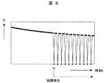
ここで特定のコアに故障が発生し、当該コアの計算結果が0になってしまった場合のTiのグラフを図8に示す。例としてコアは全部で4つとし、故障コアはそのうちの1つとする。時刻tXにおいて故障が発生したとすると、図のように時刻tx以降、断続的にグラフが途切れ、連続性を失った状態となる。これは図5で示したように周期毎に別のコアで計算を行うため、故障の発生したコアのみの計算結果が0となるためである。 FIG. 8 shows a graph of Ti when a failure occurs in a specific core and the calculation result of the core becomes zero. As an example, there are four cores in total, and one of the failed cores. If a failure occurs at time tX, the graph is intermittently interrupted after time tx as shown in FIG. This is because, as shown in FIG. 5, the calculation is performed with another core for each period, and therefore the calculation result of only the core in which the failure has occurred is zero.
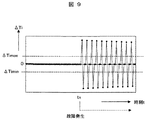
ここでステップ6の処理により今回値と前回値との差分ΔTiを計算した結果を図9に示す。ΔTiはコア故障前の時刻tx以前では0点付近を示しているが、コア故障後の時刻tx以降では断続的に上下に大きく振幅する、連続性を欠いたグラフとなっている。コア正常時のΔTiの取りうる値の下限値ΔTimin,上限値ΔTimaxを定めれば、ステップ7の故障判定処理において所定範囲をΔTimin〜ΔTimaxとすることで、範囲内であれば正常状態(ステップ8)、範囲外であれば、今回値が演算処理されたコアが、今回値が演算処理されたタイミングにおいて故障状態(ステップ9)である旨の故障判定を行うことができる。
FIG. 9 shows the result of calculating the difference ΔTi between the current value and the previous value by the processing in
また、コアに故障が発生した際に、当該コアの計算結果がランダムな値となる場合のTiのグラフを図10に示す。このような場合でも時刻tx以降では所定範囲ΔTimin〜ΔTimaxを越えるΔTiが発生するため、故障判定を行うことができる。 Further, FIG. 10 shows a graph of Ti when a calculation result of the core becomes a random value when a failure occurs in the core. Even in such a case, after time tx, ΔTi exceeding the predetermined range ΔTimin to ΔTimax occurs, so that the failure determination can be performed.
なお、本実施例においては前回値と今回値の差分を算出することで、短い周期間隔の計算結果の変化から、計算結果の時間変化の連続性を監視している。しかし、本発明の要旨は上記態様に限られず、計算結果の時間変化に連続性があるかどうかを判断できる範囲で、コア故障判断のための計算結果の比較を行う周期を定めて良い。一例としては、今回値と前々回値の差分により故障判定を行うことも可能である。また、ラジエターの温度制御のように応答性が遅く、求められる演算周期間隔が長い制御は、計算結果の比較を行う周期間隔を長く定めても連続性の判断は可能である。しかし、上述の燃料噴射制御のように応答性の速い制御に関しては、短い周期間隔で計算結果の比較を行うことが望ましい。 In the present embodiment, by calculating the difference between the previous value and the current value, the continuity of the temporal change in the calculation result is monitored from the change in the calculation result at a short cycle interval. However, the gist of the present invention is not limited to the above-described aspect, and a cycle for comparing the calculation results for determining the core failure may be determined within a range in which it can be determined whether or not the temporal change of the calculation results is continuous. As an example, it is possible to make a failure determination based on the difference between the current value and the previous value. In addition, control with a slow response and a long calculation cycle interval, such as radiator temperature control, can determine continuity even if the cycle interval for comparing the calculation results is set long. However, it is desirable to compare the calculation results at a short cycle interval with respect to control with quick response such as the fuel injection control described above.
また、本実施例において、計算結果の比較手段として二つの計算結果の差分を挙げているが、計算結果の時間変化に連続性があるかどうかを判断できる手段であれば任意の手段でよい。例えば、前回値と今回値とで除法を行い、その結果が所定範囲内かどうかを判定してもよく、また第一の計算結果,第二の計算結果,第三の計算結果の順で連続して演算処理された3つの値のうち、第二の計算結果が、第一と第三の計算結果との間の範囲に入る値であるかどうかを判定してもよい。 In the present embodiment, the difference between the two calculation results is cited as the calculation result comparison means. However, any means may be used as long as it can determine whether the temporal change of the calculation results is continuous. For example, the previous value and the current value may be divided to determine whether or not the result is within a predetermined range, and the first calculation result, the second calculation result, and the third calculation result are consecutive in this order. Then, it may be determined whether or not the second calculation result is a value that falls within a range between the first and third calculation results among the three values subjected to the arithmetic processing.
また、演算処理手段の割り当ては、計算結果の比較を行うコアが同一でなければ順番は不同であり、どのような順番であってもよい。また、演算負荷低減の観点から、同一の演算処理を同時に異なるコアでは実行しないことが望ましいが、設計上の都合により、演算処理の一部が複数のコアで同時に実行されてもよい。すなわち、あるコアで演算処理が終了する前に、次に同一の演算処理を開始しても、演算処理が重ならない時刻の演算負荷は低減できる。 Further, the assignment of the arithmetic processing means is not in the order as long as the cores for comparing the calculation results are not the same, and any order may be used. Further, from the viewpoint of reducing the calculation load, it is desirable not to execute the same calculation process in different cores at the same time, but a part of the calculation process may be executed simultaneously in a plurality of cores for convenience of design. That is, even if the same calculation process is started next before the calculation process is finished in a certain core, the calculation load at the time when the calculation processes do not overlap can be reduced.
また、本発明において利用できる演算処理手段は、計算結果の時間変化が厳密に連続性を有するものでなくてもよく、実質上一定の連続性が期待できれば良い。例えば、断続的にH出力とL出力を繰り返すPWM(Pulse Width Modulation)出力であっても、出力値の積分値は連続性を持つため、出力には実質上一定の連続性が期待できる。 Further, the arithmetic processing means that can be used in the present invention does not have to be strictly continuous with respect to the time change of the calculation result, as long as a substantially constant continuity can be expected. For example, even in the case of PWM (Pulse Width Modulation) output that repeats H output and L output intermittently, since the integrated value of the output value has continuity, the output can be expected to have substantially constant continuity.
以上が第1の実施例である。このように本方式では、監視専用のコアを設ける必要がなく、すべてのコアを通常の処理に使用できるという利点がある。また処理に冗長性を持たせて複数のコアで同時に同一の処理を実行して故障判定を行う必要もなく、コアのリソースを有効に利用できるという利点がある。また、車両の制御信号は演算周期毎に急変する可能性が低いことを利用し、車両の制御に必要な演算処理をそのまま用いて故障判定を行うため、特別なテストプログラムが不要であり、故障判定のための演算負荷の増加を抑制できるという利点がある。また、多数決比較を行う場合には少なくとも3つ以上のプロセッサまたはコアが必要となるが、本実施例の構成によれば、コアの数は2つ以上であればいくつであってもよく、コア数の制限が少ないという利点がある。 The above is the first embodiment. As described above, this method has an advantage that it is not necessary to provide a dedicated monitoring core, and all the cores can be used for normal processing. In addition, there is an advantage that the resources of the core can be used effectively without giving redundancy to the processing and performing the same processing simultaneously on a plurality of cores to perform failure determination. In addition, because it is unlikely that the vehicle control signal will change suddenly at each calculation cycle, and the failure determination is performed using the calculation processing necessary for vehicle control as it is, no special test program is required, There is an advantage that an increase in calculation load for determination can be suppressed. Further, when performing majority decision comparison, at least three processors or cores are required. However, according to the configuration of this embodiment, the number of cores may be any number as long as it is two or more. There is an advantage that the number limit is small.
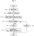
本発明の第2の実施例を説明する。第1の実施例と異なる点はステップ3の故障判定であり、この動作について図11のフローチャートを用いて説明する。
A second embodiment of the present invention will be described. The difference from the first embodiment is the failure determination in
ステップ4,ステップ5の動作は図6と同一である。ステップ5の次はステップ10に進む。ステップ10では、記憶しておいた移動平均値と今回値の差分を算出する。移動平均値については後述するステップ11で説明する。ステップ7からステップ9の動作は図6と同一である。ステップ8にて正常判定とされた場合はステップ11に進む。ステップ11では、記憶しておいた移動平均値に今回値を加味して新しい移動平均値を算出する。ここで移動平均値の計算方法は単純移動平均でも加重移動平均でもよい。また移動平均値の計算に少なくとも2回分の値が必要であるため、ステップ7の判定はタスク周期の3回目以降から行う。
図12および図13を用いて本実施例の効果について示す。図12は第1の実施例で説明した方式を用いてステップ6の処理により前回値との差分ΔTiを計算した結果のグラフである。ここでΔTiは関数Aの結果、Tiが振動状態となる事象を表している。例えば、スロットルバルブの劣化などで、Qaの制御が吸入空気量センサの入力信号に基づいて算出した所望の制御量の通り制御できない場合などが該当する。ここで所定範囲ΔTimin0〜ΔTimax0は振動の振幅の範囲が必要である。図13は同じTiについて、本実施例のステップ10の処理により前回値との差分ΔTiを移動平均値を用いて計算した結果のグラフである。このようにTiが振動状態であってもΔTiは収束するグラフとなり、所定範囲ΔTimin〜ΔTimaxは図12の所定範囲ΔTimin0〜ΔTimax0と比べて狭い範囲で収まる。
The effects of this embodiment will be described with reference to FIGS. FIG. 12 is a graph showing the result of calculating the difference ΔTi from the previous value by the process of
本実施例の構成によれば、移動平均値を用いることで差分の変動幅を抑えることができ、故障判定の所定範囲を狭く設定することができる。したがって、故障判定できる領域が多くなり、故障判定の精度を高めることができるという利点がある。以上が第2の実施例である。 According to the configuration of the present embodiment, by using the moving average value, the fluctuation range of the difference can be suppressed, and the predetermined range for failure determination can be set narrow. Therefore, there are advantages that the area where failure can be determined increases and the accuracy of failure determination can be improved. The above is the second embodiment.
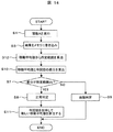
本発明の請求項3に対応する第3の実施例を説明する。第2の実施例と異なる点はステップ3の故障判定であり、この動作について図14のフローチャートを用いて説明する。
A third embodiment corresponding to claim 3 of the present invention will be described. The difference from the second embodiment is the failure determination at
ステップ4,ステップ5の動作は図6と同一である。ステップ5の次はステップ12に進む。ステップ12では、記憶しておいた移動平均値からステップ7で使用する所定範囲の算出を行う。ここで算出方法は例えば下式(数2,数3)で求めることができる。
〔数2〕
ΔTimin=−α×|移動平均値|
〔数3〕
ΔTimax=+α×|移動平均値|
[Equation 2]
ΔTimin = −α × | moving average value |
[Equation 3]
ΔTimax = + α × | moving average value |
ここでαは1以上の任意の係数であり、値を大きくすることで故障判定の誤判定を少なくすることができるが、その反面故障の検出精度が低くなるという性質を持つ。ここでは数2および数3の算出方式を例に挙げたが、移動平均値に基づいたものであればどのような算出方法であってもよい。ステップ12の次はステップ10に進む。以降のステップ10からステップ11までの動作は図11と同一である。
Here, α is an arbitrary coefficient equal to or greater than 1. Increasing the value can reduce misjudgment of failure determination, but has a property that failure detection accuracy is lowered. Here, the calculation methods of
以上が第3の実施例である。このように本方式では、所定範囲をあらかじめ設定する必要がないため、計算結果の範囲の限定が難しい関数についても最適な所定範囲を得ることができるという利点がある。また数2および数3の算出方式を採用することで、係数の設定値により故障判定の誤判定の度合いと故障の検出精度とを任意に選択できるという利点がある。
The above is the third embodiment. As described above, this method has an advantage that an optimum predetermined range can be obtained even for a function for which it is difficult to limit the range of calculation results because it is not necessary to set the predetermined range in advance. In addition, by adopting the calculation methods of
本発明の第4の実施例を説明する。第1から第3の実施例と異なる点はステップ3の故障判定であり、この動作について図15のフローチャートを用いて説明する。
A fourth embodiment of the present invention will be described. The difference from the first to third embodiments is the failure determination at
ステップ4からステップ7の動作は図6と同一である。ステップ7では、差分の値を判定する。値が所定の範囲内であればステップ8へ進み、範囲外であればステップ12へと進む。
The operation from
ステップ12では、故障カウンタを1つ増分する。ステップ13では、故障カウンタが所定回数を越えたかどうかを判定する。所定回数を越えない場合はステップ8へと進み、所定回数を越えた場合はステップ9へと進む。ステップ8およびステップ9の動作は図6と同一である。
In
ここで図15は第1の実施例の図6を元にして作成したが、第2の実施例の図11および第3の実施例の図14を元にした場合でも同様である。 Here, FIG. 15 is created based on FIG. 6 of the first embodiment, but the same applies to the case based on FIG. 11 of the second embodiment and FIG. 14 of the third embodiment.
以上が第4の実施例である。このように本方式では、ステップ7で差分の値を判定した値が所定の範囲外であっても即座に故障とは判定せず、故障カウンタを設けて判定することで、故障の誤判定を抑制できる利点がある。また故障が一時的なものであり、継続して使用できるような場合にも対応できるという利点がある。
The above is the fourth embodiment. In this way, in this method, even if the difference value determined in
本発明の第5の実施例を説明する。第1から第4の実施例と異なる点はCPU7のOSの動作であり、この動作について図16のフローチャートを用いて説明する。
A fifth embodiment of the present invention will be described. The difference from the first to fourth embodiments is the operation of the OS of the
ステップ1からステップ3の動作は図4と同一である。ステップ3で正常判定(コア故障なし)の場合はタスク処理を続行し、再びステップ3に戻る。故障判定(コア故障あり)の場合はステップ14に進む。
The operation from
ステップ14ではタスクの実行を一時中断する。ステップ15ではステップ3で故障と判定されたコアを除いた残りのコアに関数Aの処理を割り当てる処理を行う。ステップ15の次はステップ2に戻り、タスクの実行を再開する。
In
ここでステップ15の再割り当て処理について図17を用いて詳細に説明する。図17はコアA〜D(14〜17)のそれぞれコアの処理を時間軸で表している。図5との相違点について以下説明する。この例ではX+20ms後の時点でコアC16に故障が発生した場合を示している。このときまずステップ14によりタスクの実行を一時中断する。次にステップ15の再割り当て処理により、関数Aの再割り当てを行う。ここでは故障の発生したコアC16を除いた残りのコアA14,コアB15,コアD17に関数Aの処理を割り当てる処理を行う。ここで再割り当て処理は関数Aだけでなく、コアC16が行っていたすべての処理を残りのコアに割り当ててもよい。再割り当て処理のあとタスクの実行を再開する。
Here, the reallocation processing in
以上が第5の実施例である。このように本方式では、任意のコアに故障が発生した場合でも当該コアを除いた残りのコアで処理を継続するため、故障判定および制御処理を正常に続行できるという利点がある。 The above is the fifth embodiment. As described above, this method has an advantage that even when a failure occurs in an arbitrary core, the processing is continued with the remaining cores other than the core, so that the failure determination and the control processing can be normally continued.
本発明の第6の実施例を説明する。第1から第5の実施例と異なる点はステップ3の故障判定であり、この動作について図18および図19のフローチャートを用いて説明する。
A sixth embodiment of the present invention will be described. The difference from the first to fifth embodiments is the failure determination in
図18のステップ4,ステップ5の動作は図6と同一である。ステップ5の次はステップ16に進む。ステップ16では、前回の演算周期で正常と判定されたコアに割り込みイベントを発行し、この判定処理に関してこのコアでの処理は終了する。
The operations in
図19はステップ16の割り込みイベントを受けたコアでの動作を示している。ステップ6では割り込みイベントを受けた当該コアで算出された前回値と、割り込みイベントを発行したコアで算出された今回値の差分を算出する。ステップ7からステップ9までの処理は、割り込みイベントを受けた当該コアで行うことを除いては図6と同一である。
FIG. 19 shows the operation in the core that has received the interrupt event of
以上の動作についてコアA〜D(14〜17)のそれぞれコアの処理を時間軸で表したものが図20である。ここで故障判定処理23は図19の処理を表している。Xms後を例にとると、コアA14にて図18のステップ4により関数Aの処理を行い、ステップ5を経てステップ16にて前回の演算周期で正常と判定されたコアD17に割り込みイベントを発行する。割り込みイベントを受けたコアD17では図19のステップ6からステップ9で表される故障判定処理23の処理を行う。
FIG. 20 shows the processing of the cores A to D (14 to 17) on the time axis for the above operations. Here, the
以上が第6の実施例である。このように故障判定処理23を前回の演算周期で正常と判定されたコアで行うことにより、異常が発生したコアに他のコアの故障判定処理23を割り振ってしまう事態を抑制できる。例えば、コアに故障が発生してステップ6の差分計算に異常が発生し、本来所定範囲外となるはずの差分結果が所定範囲内に入ってしまう現象や、ステップ7の判定処理において本来故障と判定されるべきところが正常と判定されてしまう現象を抑制できるという利点がある。
The above is the sixth embodiment. Thus, by performing the
ここでは割り込みイベントを用いて故障判定処理23の処理を行う例を示したが、前回の演算周期で正常と判定されたコアで故障判定処理23を行う方法であれば実現手段は何でもよく、特に割り込みイベントが必須というわけではない。また、ステップ6からステップ9の処理のいずれかのみを前回の演算周期で正常と判定されたコアで行ってもよい。
Here, an example in which the
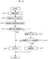
本発明の第7の実施例を説明する。第1から第5の実施例と異なる点はCPU7のOSの動作およびステップ3の故障判定であり、この動作について図21および図22のフローチャートを用いて説明する。
A seventh embodiment of the present invention will be described. The differences from the first to fifth embodiments are the operation of the OS of the
図21のステップ1からステップ2の動作は図4と同一である。ステップ2の次はステップ17を実行する。ステップ17では、少なくとも3つ以上の奇数のコアで重複して実施されたコア故障判定の結果を判定する。ここで正常判定(コア故障なし)とされたコアの数が故障判定(コア故障あり)とされたコアの数より少ない場合は正常状態とみなしてタスク処理を続行し、再びステップ17に戻る。それ以外の場合は故障状態とみなして処理を終了する。あるいは第5の実施例の図16のように再割り当て処理を行ってもよい。
The operations from
ステップ17の故障判定について図22のフローチャートを用いて説明する。ステップ4,ステップ5の動作は図6と同一である。ステップ5の次はステップ18に進む。ステップ18では、少なくとも3つ以上の奇数のコアに割り込みイベントを発行し、この判定処理に関してこのコアでの処理は終了する。割り込みイベントを受けた各コアは、図19で示される故障判定処理を行う。
The failure determination at
以上の動作についてコアA〜D(14〜17)のそれぞれコアの処理を時間軸で表したものが図23である。ここで故障判定処理23は図19の処理を表している。Xms後を例にとると、コアA14にて図18のステップ4により関数Aの処理を行い、ステップ5を経てステップ18にて少なくとも3つ以上の奇数のコアに割り込みイベントを発行する。割り込みイベントを受けた各コアでは図19のステップ6からステップ9で表される故障判定処理23の処理を行う。
FIG. 23 shows the processing of the cores A to D (14 to 17) on the time axis for the above operations. Here, the
以上が第7の実施例である。このように演算負荷の少ない故障判定処理23の処理を、少なくとも3つ以上の奇数のコアで行い、それらの結果を多数決にて判定することにより、演算負荷の増大を抑えながら、故障判定の信頼性を向上することができるという利点がある。
The above is the seventh embodiment. As described above, the
ここでは割り込みイベントを用いて故障判定処理23の処理を行う例を示したが、少なくとも3つ以上の奇数のコアで故障判定処理23を行う方法であれば実現手段は何でもよく、特に割り込みイベントが必須というわけではない。
In this example, the
また、ステップ6からステップ9の処理のいずれかのみを少なくとも3つ以上の奇数のコアで行うよう構成することで、故障判定の一部分の信頼性を向上することもできる。
In addition, by configuring only any of the processing from
本発明の第8の実施例を説明する。第1から第5の実施例と異なる点はCPU7のOSの動作およびステップ3の故障判定であり、この動作について図24および図25のフローチャートを用いて説明する。
An eighth embodiment of the present invention will be described. The differences from the first to fifth embodiments are the operation of the OS of the
図24のステップ1からステップ2の動作は図4と同一である。ステップ2の次はステップ19を実行する。ステップ19では、少なくとも2つ以上のコアで重複して実施されたコア故障判定の結果を重み付けして集計する。重み付け計算方法は例えば下式(数4)が挙げられる。
The operations from
〔数4〕
R=W1×C1+W2×C2+・・・+Wn×Cn
R:集計値
Wn:n番目のコアに対する重み付け(0〜1)
Cn:n番目のコアの判定結果値。正常判定時=0,故障判定時=1
[Equation 4]
R = W1 × C1 + W2 × C2 +... + Wn × Cn
R: Total value Wn: Weight for the nth core (0 to 1)
Cn: Determination result value of the nth core. Normal judgment = 0, failure judgment = 1
ここで重み付けは、各コアの処理内容の重要度によって定めてもよい。あるいは各コアが正常と判断されてからの経過時間によって定めてもよい。また重み付け計算方法は数4に限定されるものではなく、任意の計算方法を用いてもよい。
Here, the weighting may be determined according to the importance of the processing content of each core. Or you may determine by the elapsed time after each core is judged normal. The weighting calculation method is not limited to
ステップ20では、ステップ19で計算された集計結果を用いて故障判定を行う。例えばステップ19で前述の数4によって集計された場合、集計値Rが所定値以上であるときに故障と判定する方法が挙げられる。正常状態と判定された場合はタスク処理を続行し、再びステップ19に戻る。それ以外の場合は故障状態とみなして処理を終了する。あるいは第5の実施例の図16のように再割り当て処理を行ってもよい。
In
ステップ19の故障判定について図25のフローチャートを用いて説明する。ステップ4,ステップ5の動作は図6と同一である。ステップ5の次はステップ21に進む。ステップ21では、少なくとも2つ以上のコアに割り込みイベントを発行し、この判定処理に関してこのコアでの処理は終了する。割り込みイベントを受けた各コアは、図19で示される故障判定処理を行う。
The failure determination at
以上の動作についてコアA〜D(14〜17)のそれぞれコアの処理を時間軸で表したものが図23である。ここで故障判定処理23は図19の処理を表している。Xms後を例にとると、コアA14にて図18のステップ4により関数Aの処理を行い、ステップ5を経てステップ18にて少なくとも2つ以上のコアに割り込みイベントを発行する。割り込みイベントを受けた各コアでは図19のステップ6からステップ9で表される故障判定処理23の処理を行う。
FIG. 23 shows the processing of the cores A to D (14 to 17) on the time axis for the above operations. Here, the
以上が第8の実施例である。このように故障判定処理23を少なくとも2つ以上のコアで行い、それらの結果を重み付けして集計して判定することにより、故障判定の信頼性を向上することができるという利点がある。またコア毎に性質や重要度が異なる場合にもその性質や重要度を加味した最適な故障判断を行うことができるという利点がある。またコアの数は2つ以上であればいくつでもよく、コア数の制限を受けないという利点がある。
The above is the eighth embodiment. Thus, there is an advantage that the reliability of failure determination can be improved by performing the
ここでは割り込みイベントを用いて故障判定処理23の処理を行う例を示したが、少なくとも2つ以上のコアで故障判定処理23を行う方法であれば実現手段は何でもよく、特に割り込みイベントが必須というわけではない。
Here, an example in which the
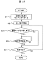
本発明の第9の実施例を説明する。第7または第8の実施例と異なる点はCPU7のOSの動作であり、この動作について図26のフローチャートを用いて説明する。
A ninth embodiment of the present invention will be described. The difference from the seventh or eighth embodiment is the operation of the OS of the
図26のステップ1からステップ2の動作は図4と同一である。ステップ2の次はステップ22を実行する。ステップ22では、少なくとも3つ以上のコアで重複して実施されたコア故障判定の結果、1つのコアだけが故障と判定し他のコアが正常と判定した場合はステップ23へと進む。それ以外の場合はステップ24へと進む。ステップ23では、ステップ22にて故障判定したコア(1つのコア)が故障状態であると判断する。
The operations from
ステップ24では、ステップ22と同様に少なくとも3つ以上のコアで重複して実施されたコア故障判定の結果、1つのコアだけが正常と判定し他のコアが故障と判定した場合は、ステップ25へと進む。それ以外の場合はステップ26へと進む。ステップ25では、ステップ24にて正常判定したコア(1つのコア)と今回の演算周期において演算したコアの両方が故障状態であると判断する。
In
ステップ26およびステップ27は、第7の実施例の図21のステップ17に相当する多数決の故障判定処理、または第8の実施例の図24のステップ19およびステップ20に相当する各コアの重み付けの集計による故障判定処理である。ステップ27で正常と判定された場合はタスク処理を続行し、再びステップ22に戻る。それ以外の場合は今回の演算周期において演算したコアが故障状態とみなして処理を終了する。あるいは第5の実施例の図16のように再割り当て処理を行ってもよい。
以上が第9の実施例である。このように故障判定処理23を少なくとも3つ以上のコアで行い、その結果1つのコアだけが故障と判定し他のコアが正常と判定した場合は、今回の演算周期において演算したコアには異常がなく、別のコア(1つのだけが故障と判定したコア)に故障が発生していると判断することで、故障の誤判定を低減することができ、かつ今回の演算周期において演算したコア以外のコアの故障を検出できるという利点がある。また1つのコアだけが正常と判定し他のコアが故障と判定した場合は、正常と判定したコアと今回の演算周期において演算したコアの両方に故障が生じていると判断することで、同時に2つのコアの故障を検出できるという利点がある。
The above is the ninth embodiment. As described above, when the
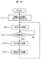
本発明の第10の実施例を説明する。第1から第9の実施例と異なる点はCPU7のOSの動作であり、この動作について図27のフローチャートを用いて説明する。
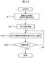
A tenth embodiment of the present invention will be described. The difference from the first to ninth embodiments is the operation of the OS of the
図27のステップ1からステップ2の動作は図4と同一である。ステップ2の次はステップ29を実行する。ステップ29では、車両の運転モードの切り替えが発生したかどうかを判定する。ここで運転モードとは車両の状態を規定するものであり、例えばガソリン噴射式内燃機関における機関停止状態,始動状態,完爆状態,セルフシャットオフ状態が挙げられる。この運転モードは故障の判定に使用する関数Aの演算に影響する可能性があるものであれば何でもよく、故障判定のために新たに規定したものであってもよい。ステップ29で運転モードの切り替えが発生した場合はステップ30へ進み、発生していない場合はステップ31へと進む。ステップ30では、運転モードの切り替え発生から所定時間が経過したかどうかを判定する。所定時間が経過している場合はステップ31へ進み、経過していない場合は再びステップ30に戻る。ステップ31の動作は図4のステップ3と同様であり、正常判定(コア故障なし)の場合はタスク処理を続行し、ステップ29に戻る。故障判定(コア故障あり)の場合は処理を終了する。あるいは第5の実施例の図16のように再割り当て処理を行ってもよい。
The operations from
以上が第10の実施例である。運転モードが変更されたときは車両の制御が大きく変動する特異点であることが多く、故障の判定に使用する関数Aの計算結果が前回値と比べて大きく変わり、連続性を失う場合が多くなる。このような場合に差分を用いた故障判定を行うと前回値との差分ΔTiが想定した所定範囲ΔTimin〜ΔTimaxを越えることがあり、故障状態と誤判定される可能性がある。本実施例はこのような運転状態が急変する事態において所定時間の故障判定休止期間を設けることで、故障の誤判定を抑制できる利点がある。 The above is the tenth embodiment. When the driving mode is changed, it is often a singular point where the control of the vehicle greatly fluctuates, and the calculation result of the function A used for determining the failure changes greatly compared to the previous value, and continuity is often lost. Become. In such a case, if the failure determination using the difference is performed, the difference ΔTi with respect to the previous value may exceed the predetermined range ΔTimin to ΔTimax, which may be erroneously determined as a failure state. The present embodiment has an advantage that an erroneous determination of a failure can be suppressed by providing a failure determination suspension period of a predetermined time in such a situation where the operating state suddenly changes.
本発明の第11の実施例を説明する。第1から第10の実施例と異なる点はステップ3の故障判定であり、この動作について図28のフローチャートを用いて説明する。
An eleventh embodiment of the present invention will be described. The difference from the first to tenth embodiments is the failure determination at
ステップ4,ステップ5の動作は図6と同一である。ステップ5の次はステップ32に進む。ステップ32では、関数Aに使用する少なくとも1つ以上の入力値のいずれかまたは複数の前回値と今回値の差分を算出する。ステップ33では、ステップ32により算出された差分の値を判定する。値が所定の範囲内であればステップ6へ進み、範囲外であればステップ34へと進む。ここで複数の入力値について判定を行う場合は、例えばそれらのすべてが範囲内であればステップ6へと進み、それ以外であればステップ34へと進む処理が挙げられるが、他の方法として入力値の重要度によって重み付けをして判定処理を行ってもよい。
ステップ6からステップ9の動作は図6と同一であり、ステップ8では、このコアは正常状態と判定する。ステップ9では、このコアは故障状態と判定する。
The operation from
ステップ34では、このコアは正常状態と判定する。ここで正常状態の代わりに「故障判定中」という状態を規定してもよい。
In
また、ステップ32からステップ34の入力値の判定処理はこの例ではステップ4の関数Aの処理と同一のコアのタスクで行っているが、第6の実施例で示したように別のコアで行ってもよい。
In addition, in this example, the input value determination process from step 32 to step 34 is performed by the same core task as the process of function A in
以上が第11の実施例である。入力値が大きく変化した場合は関数Aの実行結果も大きく変動することがあるが、この変動が第1の実施例で示した故障判定で述べた、所定範囲ΔTimin〜ΔTimaxを越えるものであった場合、故障と誤判定することになる。これを防ぐにはΔTimin〜ΔTimaxを広く取ることが必要であるが、それによって故障の検出精度が低下するという欠点がある。そこで本実施例のように、入力値が大きく変化した場合は故障判定を行わないようにすることで、故障の検出精度を保ったままで誤判定を抑制できるという利点がある。また特に誤判定を引き起こしやすい入力値を選択することや、入力値に重み付けを行うことで、より効果的に誤判定を抑制できるという利点がある。 The above is the eleventh embodiment. When the input value changes greatly, the execution result of the function A may change greatly, but this change exceeds the predetermined range ΔTimin to ΔTimax described in the failure determination shown in the first embodiment. In this case, it is erroneously determined as a failure. In order to prevent this, it is necessary to take ΔTimin to ΔTimax widely, but there is a drawback in that the failure detection accuracy decreases. Thus, as in this embodiment, there is an advantage that erroneous determination can be suppressed while maintaining failure detection accuracy by not performing failure determination when the input value changes greatly. In addition, there is an advantage that erroneous determination can be more effectively suppressed by selecting an input value that is likely to cause erroneous determination and by weighting the input value.
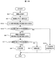
本発明の第12の実施例を説明する。第11の実施例と異なる点はステップ3の故障判定であり、この動作について図29のフローチャートを用いて説明する。
A twelfth embodiment of the present invention will be described. The difference from the eleventh embodiment is the failure determination at
ステップ4,ステップ5の動作は図6と同一である。ステップ5の次はステップ32に進む。ステップ35では、関数Aに使用する少なくとも1つ以上の入力値のいずれかまたは複数の前回までの移動平均値と今回値の差分を算出する。ステップ36では、前回までの移動平均値に今回値を加味して新しい移動平均値を算出する。ここで移動平均値の計算方法は単純移動平均でも加重移動平均でもよい。ステップ33以降の動作は図28と同一である。また移動平均値の計算に少なくとも2回分の値が必要であるため、ステップ33の判定はタスク周期の3回目以降から行う。
以上が第12の実施例である。第11の実施例では入力値が振動状態のように変動する場合、その前回値と今回値との差分は第2の実施例の図12で示したΔTiのグラフと同様に0点を挟んで上下に振動するグラフとなる。このような場合、故障判定の機会を増やすためには入力値の判定に用いる所定範囲を広く取る必要があるが、その場合入力値が所定範囲内で大きく変化すると関数Aの実行結果も大きく変動し、正常状態であるにもかかわらず故障と誤判定する可能性がある。そこで本実施例のように移動平均値を用いることにより、第11の実施例の図13と同様に差分の振幅が小さくなるため、入力値の判定に用いる所定範囲を狭くすることが可能になる。これにより故障判定の機会を減らさずに、かつ入力値が急変動しても故障と誤判定するのを抑制することができるという利点がある。 The above is the twelfth embodiment. In the eleventh embodiment, when the input value fluctuates as in a vibration state, the difference between the previous value and the current value is 0 points as in the graph of ΔTi shown in FIG. 12 of the second embodiment. The graph vibrates up and down. In such a case, in order to increase the chance of failure determination, it is necessary to widen the predetermined range used for determining the input value. In this case, if the input value changes greatly within the predetermined range, the execution result of the function A also varies greatly. In spite of the normal state, there is a possibility of erroneous determination as a failure. Therefore, by using the moving average value as in the present embodiment, the difference amplitude is reduced in the same manner as in FIG. 13 of the eleventh embodiment, so that the predetermined range used for determining the input value can be narrowed. . As a result, there is an advantage that it is possible to suppress erroneous determination as failure even if the input value fluctuates suddenly without reducing the chance of failure determination.
本発明の第13の実施例を説明する。第12の実施例と異なる点はステップ3の故障判定であり、この動作について図30のフローチャートを用いて説明する。
A thirteenth embodiment of the present invention will be described. The difference from the twelfth embodiment is the failure determination in
ステップ4,ステップ5の動作は図6と同一である。ステップ5の次はステップ37に進む。ステップ37では、記憶しておいた入力値の移動平均値からステップ7で使用する所定範囲の算出を行う。ここで算出方法は例えば下式(数5,数6)で求めることができる。
〔数5〕
ΔIAMINn=−αian×|IAn|
〔数6〕
ΔIAMAXn=+αian×|IAn|
ΔIAMINn:n番目の入力値の判定用範囲の下限値
ΔIAMAXn:n番目の入力値の判定用範囲の上限値
αian:n番目の入力値の判定用範囲算出係数
IAn:n番目の入力値の移動平均値
[Equation 5]
ΔIAMINn = −αian × | IAn |
[Equation 6]
ΔIAMAXn = + αian × | IAn |
ΔIAMINn: Lower limit value for nth input value determination range ΔIAMAXn: Upper limit value for nth input value determination range
αian: nth input value determination range calculation coefficient
IAn: Moving average value of the nth input value
ここでαianは1以上の任意の係数であり、値を大きくすることで故障判定の機会を増やすことができるが、その反面故障と誤判定する可能性も増加する。ここでは数5および数6の算出方式を例に挙げたが、移動平均値に基づいたものであればどのような算出方法であってもよい。ステップ37の次はステップ35に進む。ステップ35以降の動作は図29と同一である。
Here, αian is an arbitrary coefficient of 1 or more, and increasing the value can increase the chance of failure determination, but on the other hand, the possibility of erroneous determination as failure also increases. Here, the calculation methods of
以上が第13の実施例である。このように本方式では、入力値判定用の所定範囲をあらかじめ設定する必要がないため、入力値の取りうる範囲の限定が難しい場合においても最適な所定範囲を得ることができるという利点がある。また数5および数6の算出方式を採用することで、係数の設定値により故障判定の誤判定の度合いと故障判定の機会の頻度とを任意に選択できるという利点がある。
The above is the thirteenth embodiment. As described above, this method has an advantage that an optimum predetermined range can be obtained even when it is difficult to limit the range that can be taken by the input value because it is not necessary to set a predetermined range for determining the input value in advance. Further, by adopting the calculation methods of
1 演算処理割り当て手段
2 演算処理手段
3 記憶手段
4 差分判定手段
5 コア故障判断手段
6 制御コントロールユニット(C/U)
7 マイクロコンピュータ(CPU)
8 読み取り専用記憶装置(ROM)
9 読み書き可能記憶装置(RAM)
10 車両
11 車両に備えられたセンサ
12 車両に備えられたアクチュエータ
13 入出力装置(I/O)
14〜17 コアA〜D
18 データバス
19 I/Oポート
20 データ読み込みポート
21 データ書き込みポート
22 車両の制御に関わる処理関数A
23 故障判定処理
DESCRIPTION OF
7 Microcomputer (CPU)
8 Read-only memory (ROM)
9 Read / write memory device (RAM)
DESCRIPTION OF
14-17 Core A-D
18 Data bus 19 I /
23 Failure judgment processing
Claims (21)
連続的に変化する入力値を取得し、前記機器の制御に必要な出力値を演算する演算処理手段を備え、
前記演算処理手段が前記複数のコア中の特定のコアにおいて特定のタイミングで演算処理を行った出力値と、
前記特定のコアとは異なる、前記複数のコア中の他のコアにおいて、
前記演算処理手段が前記特定のタイミングとは異なるタイミングで演算処理を行った出力値と、
の比較を行い、前記特定のコアに故障が生じていると判断するコア故障判断手段を備えることを特徴とする車両制御用マルチコアシステム。 A multi-core system for vehicle control for controlling equipment mounted on a vehicle using a plurality of cores,
An operation processing means for acquiring an input value that continuously changes and calculating an output value necessary for controlling the device,
An output value of performing arithmetic processing at a specific timing in a particular core in the arithmetic processing means of said plurality of cores,
In another core in the plurality of cores different from the specific core,
An output value obtained by the arithmetic processing means performing arithmetic processing at a timing different from the specific timing;
A multi-core system for vehicle control, comprising: a core failure judging means for judging that a failure has occurred in the specific core.
前記演算処理手段の演算処理が実行されるコアが切り替わることによって、
前記演算処理手段の出力値の連続性が失われたときに、
前記特定のコアに故障が生じていると判断することを特徴とする請求項1に記載の車両制御用マルチコアシステム。 The core failure determination means is
By switching the core on which the arithmetic processing of the arithmetic processing means is performed,
When the continuity of the output value of the arithmetic processing means is lost,
2. The multi-core system for vehicle control according to claim 1, wherein it is determined that a failure has occurred in the specific core.
前記特定のコアに故障が生じていると判断することを特徴とする請求項1から3いずれかに記載の車両制御用マルチコアシステム。 The multi-core system for vehicle control includes a difference determination unit that determines a difference between output values having different execution cores and timings, and determines whether the difference is within a predetermined range. According to the determination result of the difference determination means,
The multi-core system for vehicle control according to any one of claims 1 to 3, wherein it is determined that a failure has occurred in the specific core.
前記演算処理割り当て手段は、前記コア故障判断手段によって前記特定のコアに故障が生じていると判断された場合、前記特定のコアを割り当ての対象から除外して再度割り当てることを特徴とする請求項1から7のいずれかに記載の車両制御用マルチコアシステム。 The multi-core system for vehicle control includes arithmetic processing assigning means that divides the arithmetic processing means and assigns the plurality of cores so that the core on which the arithmetic processing is executed is switched according to the execution timing.
The arithmetic processing assigning unit, when it is determined by the core failure determining unit that a failure has occurred in the specific core, the specific core is excluded from allocation targets and reassigned. The multi-core system for vehicle control according to any one of 1 to 7.
演算処理を行うタイミングは、
前記機器の動作に同期して決定することを特徴とする請求項1から17いずれかに記載の車両制御用マルチコアシステム。 The arithmetic processing means is assigned to the plurality of cores,
The timing to perform the calculation process is
The multi-core system for vehicle control according to any one of claims 1 to 17, wherein the multi-core system is determined in synchronization with an operation of the device.
前記特定のコアとは異なる、前記複数のコア中の他のコアにおいて、
前記演算処理手段が前記特定のタイミングとは異なるタイミングで演算処理を行った出力値と、の比較を行い、前記特定のコアに故障が生じていると判断するコア故障判断手段を備えることを特徴とする内燃機関の制御装置。 A control device for an internal combustion engine having a plurality of cores for controlling the internal combustion engine , comprising: an arithmetic processing means for acquiring continuously changing input values and calculating an output value necessary for controlling the internal combustion engine An output value obtained by performing arithmetic processing at a specific timing in a specific core among the plurality of cores,
In another core in the plurality of cores different from the specific core,
Comparing with an output value obtained by performing arithmetic processing at a timing different from the specific timing, the arithmetic processing means includes core failure determining means for determining that a failure has occurred in the specific core. A control device for an internal combustion engine.
前記演算処理手段の演算処理が実行されるコアが切り替わることによって、
前記演算処理手段の出力値の連続性が失われたときに、
前記特定のコアに故障が生じていると判断する
ことを特徴とする請求項19に記載の内燃機関の制御装置。 The core failure determination means is
By switching the core on which the arithmetic processing of the arithmetic processing means is performed,
When the continuity of the output value of the arithmetic processing means is lost,
20. The control device for an internal combustion engine according to claim 19, wherein it is determined that a failure has occurred in the specific core.
演算処理が実行されるコアが切り替わるように前記複数のコアに割り当てる、
演算処理割り当て手段を備え、
前記演算処理割り当て手段は、
前記演算処理手段を前記複数のコアに割り当てるタイミングを、
前記内燃機関の動作に同期して決定することを特徴とする請求項19または20いずれかに記載の内燃機関の制御装置。 Dividing the arithmetic processing means and assigning to the plurality of cores so that the core on which the arithmetic processing is executed is switched according to the execution timing;
Computation processing means is provided,
The arithmetic processing assigning means includes
Timing for assigning the arithmetic processing means to the plurality of cores,
21. The control device for an internal combustion engine according to claim 19, wherein the control device is determined in synchronization with an operation of the internal combustion engine.
Priority Applications (4)
| Application Number | Priority Date | Filing Date | Title |
|---|---|---|---|
| JP2008303369A JP4709268B2 (en) | 2008-11-28 | 2008-11-28 | Multi-core system for vehicle control or control device for internal combustion engine |
| US12/625,266 US8417990B2 (en) | 2008-11-28 | 2009-11-24 | Multi-core processing system for vehicle control or an internal combustion engine controller |
| AT09177078T ATE545086T1 (en) | 2008-11-28 | 2009-11-25 | MULTI-CORE PROCESSING SYSTEM FOR VEHICLE CONTROL OR AN COMBUSTION ENGINE CONTROLLER |
| EP09177078A EP2192489B1 (en) | 2008-11-28 | 2009-11-25 | Multi-core processing system for vehicle control or an internal combustion engine controller |
Applications Claiming Priority (1)
| Application Number | Priority Date | Filing Date | Title |
|---|---|---|---|
| JP2008303369A JP4709268B2 (en) | 2008-11-28 | 2008-11-28 | Multi-core system for vehicle control or control device for internal combustion engine |
Publications (2)
| Publication Number | Publication Date |
|---|---|
| JP2010126012A JP2010126012A (en) | 2010-06-10 |
| JP4709268B2 true JP4709268B2 (en) | 2011-06-22 |
Family
ID=41718918
Family Applications (1)
| Application Number | Title | Priority Date | Filing Date |
|---|---|---|---|
| JP2008303369A Expired - Fee Related JP4709268B2 (en) | 2008-11-28 | 2008-11-28 | Multi-core system for vehicle control or control device for internal combustion engine |
Country Status (4)
| Country | Link |
|---|---|
| US (1) | US8417990B2 (en) |
| EP (1) | EP2192489B1 (en) |
| JP (1) | JP4709268B2 (en) |
| AT (1) | ATE545086T1 (en) |
Cited By (1)
| Publication number | Priority date | Publication date | Assignee | Title |
|---|---|---|---|---|
| US10430301B2 (en) | 2016-03-14 | 2019-10-01 | Electronics And Telecommunications Research Institute | Processor system and fault detection method thereof |
Families Citing this family (20)
| Publication number | Priority date | Publication date | Assignee | Title |
|---|---|---|---|---|
| WO2011152355A1 (en) | 2010-06-01 | 2011-12-08 | 日本精工株式会社 | Sliding device |
| US20120221884A1 (en) * | 2011-02-28 | 2012-08-30 | Carter Nicholas P | Error management across hardware and software layers |
| JP5341957B2 (en) | 2011-07-20 | 2013-11-13 | トヨタ自動車株式会社 | Control device for internal combustion engine |
| JP5644949B2 (en) * | 2011-09-12 | 2014-12-24 | トヨタ自動車株式会社 | Control device for internal combustion engine |
| US9619309B2 (en) * | 2012-12-28 | 2017-04-11 | Intel Corporation | Enforcing different operational configurations for different tasks for failure rate based control of processors |
| KR101457557B1 (en) * | 2013-01-18 | 2014-11-04 | 연세대학교 산학협력단 | Multi-core device, test device and method for diagnosing failure |
| US9135126B2 (en) | 2013-02-07 | 2015-09-15 | International Business Machines Corporation | Multi-core re-initialization failure control system |
| JP6268071B2 (en) * | 2014-09-17 | 2018-01-24 | 日立オートモティブシステムズ株式会社 | Electronic control unit |
| JP2016125436A (en) * | 2015-01-07 | 2016-07-11 | 日立オートモティブシステムズ株式会社 | Engine control system |
| JP6393628B2 (en) * | 2015-01-21 | 2018-09-19 | 日立オートモティブシステムズ株式会社 | Vehicle control device |
| US9694765B2 (en) * | 2015-04-20 | 2017-07-04 | Hitachi, Ltd. | Control system for an automotive vehicle |
| JP2017033236A (en) * | 2015-07-31 | 2017-02-09 | 日立オートモティブシステムズ株式会社 | Vehicle controller |
| DE102015222321A1 (en) * | 2015-11-12 | 2017-05-18 | Siemens Aktiengesellschaft | Method for operating a multi-core processor |
| DE102017201032A1 (en) * | 2017-01-23 | 2018-05-03 | Zf Friedrichshafen Ag | Redundant processor architecture |
| US10672206B2 (en) * | 2017-12-11 | 2020-06-02 | GM Global Technology Operations LLC | Systems, methods and apparatuses for diagnostic fault detection by parameter data using a redundant processor architecture |
| US11475723B2 (en) * | 2017-12-29 | 2022-10-18 | Robert Bosch Gmbh | Determining a fault in an electronic controller |
| US20190243698A1 (en) * | 2018-02-02 | 2019-08-08 | Robert Bosch Gmbh | Electronic Control Unit for Flexible Replacement of Replaceable Components in a Vehicle |
| US11106205B2 (en) | 2018-09-18 | 2021-08-31 | Raytheon Technologies Corporation | Vehicle control with functional redundancy |
| US11520297B2 (en) * | 2019-03-29 | 2022-12-06 | Intel Corporation | Enhancing diagnostic capabilities of computing systems by combining variable patrolling API and comparison mechanism of variables |
| JP7306865B2 (en) * | 2019-04-19 | 2023-07-11 | 日立Astemo株式会社 | Arithmetic unit |
Citations (6)
| Publication number | Priority date | Publication date | Assignee | Title |
|---|---|---|---|---|
| JP2006164277A (en) * | 2004-12-02 | 2006-06-22 | Robert Bosch Gmbh | Device and method for removing error in processor, and processor |
| JP2006260568A (en) * | 2005-03-15 | 2006-09-28 | Intel Corp | Multi-core processor having active and inactive execution cores |
| JP2008010959A (en) * | 2006-06-27 | 2008-01-17 | Yokogawa Electric Corp | Signal processor and processing method |
| JP2008518296A (en) * | 2004-10-25 | 2008-05-29 | ローベルト ボッシュ ゲゼルシャフト ミット ベシュレンクテル ハフツング | Method and apparatus for switching in a computer system comprising at least two execution units |
| JP2008257589A (en) * | 2007-04-06 | 2008-10-23 | Toyota Motor Corp | Multiprocessor system with processor abnormality monitoring function |
| JP2009516277A (en) * | 2005-11-18 | 2009-04-16 | ローベルト ボッシュ ゲゼルシャフト ミット ベシュレンクテル ハフツング | Apparatus and method for eliminating errors in a system having at least two registered processing units |
Family Cites Families (17)
| Publication number | Priority date | Publication date | Assignee | Title |
|---|---|---|---|---|
| US5012409A (en) * | 1988-03-10 | 1991-04-30 | Fletcher Mitchell S | Operating system for a multi-tasking operating environment |
| CA1327838C (en) * | 1988-06-13 | 1994-03-15 | Fred Zacouto | Implantable device to prevent blood clotting disorders |
| JPH07120294B2 (en) | 1988-10-24 | 1995-12-20 | 株式会社日立製作所 | Fault tolerant method and system |
| JPH03196232A (en) | 1989-12-25 | 1991-08-27 | Nec Corp | Multiprocessor and its abnormality diagnostic method |
| GB2255838A (en) * | 1991-05-13 | 1992-11-18 | Gen Electric | Filtered signal validation. |
| JPH0773059A (en) * | 1993-03-02 | 1995-03-17 | Tandem Comput Inc | Fault-tolerant computer system |
| JPH06332874A (en) | 1993-05-24 | 1994-12-02 | Fujitsu Ltd | Test program starting method |
| JPH0916535A (en) | 1995-06-27 | 1997-01-17 | Mitsubishi Electric Corp | Multiprocessor computer |
| US6609031B1 (en) * | 1996-06-07 | 2003-08-19 | Advanced Neuromodulation Systems, Inc. | Multiprogrammable tissue stimulator and method |
| US6735474B1 (en) * | 1998-07-06 | 2004-05-11 | Advanced Bionics Corporation | Implantable stimulator system and method for treatment of incontinence and pain |
| GB2373861B (en) * | 2001-03-30 | 2004-07-28 | Visteon Global Tech Inc | Motor vehicle engine synchronisation |
| US6928583B2 (en) * | 2001-04-11 | 2005-08-09 | Stratus Technologies Bermuda Ltd. | Apparatus and method for two computing elements in a fault-tolerant server to execute instructions in lockstep |
| JP3606281B2 (en) * | 2002-06-07 | 2005-01-05 | オムロン株式会社 | Programmable controller, CPU unit, special function module, and duplex processing method |
| EP1398699A1 (en) * | 2002-09-12 | 2004-03-17 | Siemens Aktiengesellschaft | Method for synchronizing events, in particular for fault-tolerant systems |
| US7200443B2 (en) * | 2003-10-07 | 2007-04-03 | John Faul | Transcutaneous electrical nerve stimulator for appetite control |
| US8214047B2 (en) * | 2004-09-27 | 2012-07-03 | Advanced Neuromodulation Systems, Inc. | Method of using spinal cord stimulation to treat gastrointestinal and/or eating disorders or conditions |
| US20070294559A1 (en) * | 2004-10-25 | 2007-12-20 | Thomas Kottke | Method and Device for Delaying Access to Data and/or Instructions of a Multiprocessor System |
-
2008
- 2008-11-28 JP JP2008303369A patent/JP4709268B2/en not_active Expired - Fee Related
-
2009
- 2009-11-24 US US12/625,266 patent/US8417990B2/en active Active
- 2009-11-25 AT AT09177078T patent/ATE545086T1/en active
- 2009-11-25 EP EP09177078A patent/EP2192489B1/en not_active Not-in-force
Patent Citations (6)
| Publication number | Priority date | Publication date | Assignee | Title |
|---|---|---|---|---|
| JP2008518296A (en) * | 2004-10-25 | 2008-05-29 | ローベルト ボッシュ ゲゼルシャフト ミット ベシュレンクテル ハフツング | Method and apparatus for switching in a computer system comprising at least two execution units |
| JP2006164277A (en) * | 2004-12-02 | 2006-06-22 | Robert Bosch Gmbh | Device and method for removing error in processor, and processor |
| JP2006260568A (en) * | 2005-03-15 | 2006-09-28 | Intel Corp | Multi-core processor having active and inactive execution cores |
| JP2009516277A (en) * | 2005-11-18 | 2009-04-16 | ローベルト ボッシュ ゲゼルシャフト ミット ベシュレンクテル ハフツング | Apparatus and method for eliminating errors in a system having at least two registered processing units |
| JP2008010959A (en) * | 2006-06-27 | 2008-01-17 | Yokogawa Electric Corp | Signal processor and processing method |
| JP2008257589A (en) * | 2007-04-06 | 2008-10-23 | Toyota Motor Corp | Multiprocessor system with processor abnormality monitoring function |
Cited By (1)
| Publication number | Priority date | Publication date | Assignee | Title |
|---|---|---|---|---|
| US10430301B2 (en) | 2016-03-14 | 2019-10-01 | Electronics And Telecommunications Research Institute | Processor system and fault detection method thereof |
Also Published As
| Publication number | Publication date |
|---|---|
| US20100138693A1 (en) | 2010-06-03 |
| JP2010126012A (en) | 2010-06-10 |
| EP2192489B1 (en) | 2012-02-08 |
| ATE545086T1 (en) | 2012-02-15 |
| EP2192489A1 (en) | 2010-06-02 |
| US8417990B2 (en) | 2013-04-09 |
Similar Documents
| Publication | Publication Date | Title |
|---|---|---|
| JP4709268B2 (en) | Multi-core system for vehicle control or control device for internal combustion engine | |
| JP5867495B2 (en) | Electronic control unit | |
| JPH05147477A (en) | Vehicular control device | |
| JP5316128B2 (en) | Fault diagnosis system, electronic control unit, fault diagnosis method | |
| JP5515792B2 (en) | Internal combustion engine control device | |
| US20180259577A1 (en) | Electronic control apparatus and method | |
| EP2910759B1 (en) | Torque control device for vehicle | |
| JP2003323353A (en) | Memory diagnostic device and control device | |
| KR20070068405A (en) | Data processing system with a variable clock speed | |
| US8954794B2 (en) | Method and system for detection of latent faults in microcontrollers | |
| JP5226653B2 (en) | In-vehicle control device | |
| US20210124635A1 (en) | Multicore system | |
| JP5978873B2 (en) | Electronic control unit | |
| JP6094387B2 (en) | Control device | |
| CN103423011A (en) | Semiconductor data processing apparatus and engine control apparatus | |
| JP4820679B2 (en) | Electronic control device for vehicle | |
| JP6466269B2 (en) | Electronic control device and stack area usage monitoring method | |
| US9740584B2 (en) | Method and device for testing a computer core in a processor having at least two computer cores | |
| JPH0717337A (en) | Judgement of trouble of electronic controlled unit and trouble judging device | |
| JP6771272B2 (en) | In-vehicle electronic control device and stack usage | |
| JPH06305376A (en) | Control device for vehicle | |
| JPH1131011A (en) | Fault detecting device for electronic control system | |
| JP2021152338A (en) | Controller | |
| JP2019135656A (en) | Electronic control device and method of using stack | |
| JP2014096042A (en) | Electronic control device |
Legal Events
| Date | Code | Title | Description |
|---|---|---|---|
| A621 | Written request for application examination |
Free format text: JAPANESE INTERMEDIATE CODE: A621 Effective date: 20100908 |
|
| A521 | Request for written amendment filed |
Free format text: JAPANESE INTERMEDIATE CODE: A523 Effective date: 20100908 |
|
| A131 | Notification of reasons for refusal |
Free format text: JAPANESE INTERMEDIATE CODE: A131 Effective date: 20101109 |
|
| A521 | Request for written amendment filed |
Free format text: JAPANESE INTERMEDIATE CODE: A523 Effective date: 20110104 |
|
| TRDD | Decision of grant or rejection written | ||
| A01 | Written decision to grant a patent or to grant a registration (utility model) |
Free format text: JAPANESE INTERMEDIATE CODE: A01 Effective date: 20110215 |
|
| A61 | First payment of annual fees (during grant procedure) |
Free format text: JAPANESE INTERMEDIATE CODE: A61 Effective date: 20110317 |
|
| R150 | Certificate of patent or registration of utility model |
Ref document number: 4709268 Country of ref document: JP Free format text: JAPANESE INTERMEDIATE CODE: R150 |
|
| S533 | Written request for registration of change of name |
Free format text: JAPANESE INTERMEDIATE CODE: R313533 |
|
| R350 | Written notification of registration of transfer |
Free format text: JAPANESE INTERMEDIATE CODE: R350 |
|
| LAPS | Cancellation because of no payment of annual fees |