EP3249291B1 - Deckenleuchte zum einbau in eine brandschutzdecke - Google Patents
Deckenleuchte zum einbau in eine brandschutzdecke Download PDFInfo
- Publication number
- EP3249291B1 EP3249291B1 EP17000704.1A EP17000704A EP3249291B1 EP 3249291 B1 EP3249291 B1 EP 3249291B1 EP 17000704 A EP17000704 A EP 17000704A EP 3249291 B1 EP3249291 B1 EP 3249291B1
- Authority
- EP
- European Patent Office
- Prior art keywords
- housing
- ceiling
- ceiling light
- light according
- carrier
- Prior art date
- Legal status (The legal status is an assumption and is not a legal conclusion. Google has not performed a legal analysis and makes no representation as to the accuracy of the status listed.)
- Not-in-force
Links
- 238000009434 installation Methods 0.000 title claims description 6
- 230000004888 barrier function Effects 0.000 claims description 20
- 229910000831 Steel Inorganic materials 0.000 claims description 10
- 239000010959 steel Substances 0.000 claims description 10
- 229910052782 aluminium Inorganic materials 0.000 claims description 8
- XAGFODPZIPBFFR-UHFFFAOYSA-N aluminium Chemical compound [Al] XAGFODPZIPBFFR-UHFFFAOYSA-N 0.000 claims description 8
- OKTJSMMVPCPJKN-UHFFFAOYSA-N Carbon Chemical compound [C] OKTJSMMVPCPJKN-UHFFFAOYSA-N 0.000 claims description 6
- 229910002804 graphite Inorganic materials 0.000 claims description 6
- 239000010439 graphite Substances 0.000 claims description 6
- 239000011521 glass Substances 0.000 claims description 5
- 239000003365 glass fiber Substances 0.000 claims description 5
- 239000008187 granular material Substances 0.000 claims description 5
- 239000004952 Polyamide Substances 0.000 claims description 4
- 230000002093 peripheral effect Effects 0.000 claims description 4
- 229920002647 polyamide Polymers 0.000 claims description 4
- 229910052918 calcium silicate Inorganic materials 0.000 claims description 3
- 239000000378 calcium silicate Substances 0.000 claims description 3
- OYACROKNLOSFPA-UHFFFAOYSA-N calcium;dioxido(oxo)silane Chemical compound [Ca+2].[O-][Si]([O-])=O OYACROKNLOSFPA-UHFFFAOYSA-N 0.000 claims description 3
- 239000002131 composite material Substances 0.000 claims description 3
- 239000000835 fiber Substances 0.000 claims description 3
- 239000010935 stainless steel Substances 0.000 claims description 3
- 229910001220 stainless steel Inorganic materials 0.000 claims description 3
- 230000003213 activating effect Effects 0.000 claims 1
- 239000004411 aluminium Substances 0.000 claims 1
- 239000011152 fibreglass Substances 0.000 claims 1
- 239000000463 material Substances 0.000 description 6
- 239000000853 adhesive Substances 0.000 description 4
- 230000001070 adhesive effect Effects 0.000 description 4
- BASFCYQUMIYNBI-UHFFFAOYSA-N platinum Chemical compound [Pt] BASFCYQUMIYNBI-UHFFFAOYSA-N 0.000 description 4
- 239000000919 ceramic Substances 0.000 description 3
- 230000008018 melting Effects 0.000 description 3
- 238000002844 melting Methods 0.000 description 3
- 235000019353 potassium silicate Nutrition 0.000 description 3
- NTHWMYGWWRZVTN-UHFFFAOYSA-N sodium silicate Chemical compound [Na+].[Na+].[O-][Si]([O-])=O NTHWMYGWWRZVTN-UHFFFAOYSA-N 0.000 description 3
- 230000007704 transition Effects 0.000 description 3
- 239000003795 chemical substances by application Substances 0.000 description 2
- 239000004020 conductor Substances 0.000 description 2
- 230000017525 heat dissipation Effects 0.000 description 2
- 229910052751 metal Inorganic materials 0.000 description 2
- 239000002184 metal Substances 0.000 description 2
- 239000011490 mineral wool Substances 0.000 description 2
- 230000009993 protective function Effects 0.000 description 2
- 239000000779 smoke Substances 0.000 description 2
- 210000002105 tongue Anatomy 0.000 description 2
- 229910045601 alloy Inorganic materials 0.000 description 1
- 239000000956 alloy Substances 0.000 description 1
- 238000005452 bending Methods 0.000 description 1
- 229910010293 ceramic material Inorganic materials 0.000 description 1
- 238000000576 coating method Methods 0.000 description 1
- 150000001875 compounds Chemical class 0.000 description 1
- 230000000694 effects Effects 0.000 description 1
- 238000010292 electrical insulation Methods 0.000 description 1
- 150000002148 esters Chemical class 0.000 description 1
- 239000002657 fibrous material Substances 0.000 description 1
- 239000003546 flue gas Substances 0.000 description 1
- 239000011810 insulating material Substances 0.000 description 1
- 238000009413 insulation Methods 0.000 description 1
- 239000012774 insulation material Substances 0.000 description 1
- 239000000155 melt Substances 0.000 description 1
- 239000004033 plastic Substances 0.000 description 1
- 229920001296 polysiloxane Polymers 0.000 description 1
- 238000004080 punching Methods 0.000 description 1
- 230000000630 rising effect Effects 0.000 description 1
- 239000013464 silicone adhesive Substances 0.000 description 1
- 239000007787 solid Substances 0.000 description 1
Images


Classifications
-
- F—MECHANICAL ENGINEERING; LIGHTING; HEATING; WEAPONS; BLASTING
- F21—LIGHTING
- F21S—NON-PORTABLE LIGHTING DEVICES; SYSTEMS THEREOF; VEHICLE LIGHTING DEVICES SPECIALLY ADAPTED FOR VEHICLE EXTERIORS
- F21S8/00—Lighting devices intended for fixed installation
- F21S8/02—Lighting devices intended for fixed installation of recess-mounted type, e.g. downlighters
- F21S8/024—Lighting devices intended for fixed installation of recess-mounted type, e.g. downlighters intended to be recessed in a wall or like vertical structure, e.g. building facade
-
- F—MECHANICAL ENGINEERING; LIGHTING; HEATING; WEAPONS; BLASTING
- F21—LIGHTING
- F21S—NON-PORTABLE LIGHTING DEVICES; SYSTEMS THEREOF; VEHICLE LIGHTING DEVICES SPECIALLY ADAPTED FOR VEHICLE EXTERIORS
- F21S8/00—Lighting devices intended for fixed installation
- F21S8/02—Lighting devices intended for fixed installation of recess-mounted type, e.g. downlighters
- F21S8/026—Lighting devices intended for fixed installation of recess-mounted type, e.g. downlighters intended to be recessed in a ceiling or like overhead structure, e.g. suspended ceiling
-
- F—MECHANICAL ENGINEERING; LIGHTING; HEATING; WEAPONS; BLASTING
- F21—LIGHTING
- F21V—FUNCTIONAL FEATURES OR DETAILS OF LIGHTING DEVICES OR SYSTEMS THEREOF; STRUCTURAL COMBINATIONS OF LIGHTING DEVICES WITH OTHER ARTICLES, NOT OTHERWISE PROVIDED FOR
- F21V25/00—Safety devices structurally associated with lighting devices
- F21V25/12—Flameproof or explosion-proof arrangements
- F21V25/125—Flameproof or explosion-proof arrangements using intumescent material, i.e. using materials which swells up as a result of heat exposure
-
- F—MECHANICAL ENGINEERING; LIGHTING; HEATING; WEAPONS; BLASTING
- F21—LIGHTING
- F21V—FUNCTIONAL FEATURES OR DETAILS OF LIGHTING DEVICES OR SYSTEMS THEREOF; STRUCTURAL COMBINATIONS OF LIGHTING DEVICES WITH OTHER ARTICLES, NOT OTHERWISE PROVIDED FOR
- F21V29/00—Protecting lighting devices from thermal damage; Cooling or heating arrangements specially adapted for lighting devices or systems
- F21V29/15—Thermal insulation
Definitions
- the invention relates to a ceiling light for installation in a fire blanket, especially on board ships.
- the invention relates to a fire blanket.
- Fire blankets should prevent fire and smoke from reaching the area above the fire blanket in the event of fire (at a location below the fire blanket).
- the fire blanket consists of a lower, stable refractory layer of sheet steel, an upper stable refractory layer of sheet steel and a medium, well-insulating layer of rock wool.
- ceiling lights can be used, so-called downlights.
- the ceiling lights radiate light and heat down, while electrical energy is supplied via lines from above.
- the ceiling lights interrupt the fire blanket and its protective function.
- Modern ceiling lights have light sources with LEDs.
- the LEDs are controlled by electronic components on a circuit board. Both the LEDs themselves and the board emit heat during operation. To avoid local heat islands, the heat should be dissipated.
- the WO 2015/046850 A1 (according to the post-published US 2016/0230937 A1 ) discloses a luminaire with LED bulbs and for installation in a ceiling. Several LEDs are held on a box-like carrier. Above the carrier is a provided bell-shaped cover, which receives a board for controlling the light source. The cover rests on a base plate. Between housing-like support and base plate is formed as a thermal barrier, a cavity.
- the EP 1 726 873 A1 discloses a refractory ceiling light with a swellable material as a filling.
- the EP 2 999 300 A1 discloses a light and heat radiator with LED lights.
- a jacket core is filled with a free-flowing insulation material.
- the DE 81 07 035 U1 discloses a ceiling recessed light enclosed by a fire protection box, for example for fire protection ceilings.
- Side walls of the fire protection box are molded parts made of high-strength ceramic fiber material.
- the US 2008/0165545 A1 discloses a ceiling light with fire protection box, wherein a junction box is provided outside of the fire protection box.
- the US 2008/0170404 A1 discloses a refractory ceiling light with fire protection box, which may contain a swellable material.
- Object of the present invention is to provide a ceiling light for installation in a fire blanket, the protective function of the fire blanket is maintained. In addition, a good heat dissipation during operation should be ensured.
- the thermal barrier over the carrier prevents heat transfer from the underside of the ceiling people to the top of the same. This also protects the board from excessive heat and reaching a critical temperature.
- the housing is in particular, as well as the thermal barrier, made of a thermally insulating material.
- the housing extends beyond the fire blanket. Accordingly, the housing can protrude upward from the fire blanket.
- the support is made of aluminum or a conventional AlMg alloy and / or has a thermal conductivity of about 150 W / (mK) or more. As a result, a high LED heat output is dissipated. In case of fire, the aluminum carrier melts at around 650 degrees Celsius at the latest. At lower LED heat output, the support may also be made of steel or other materials with slightly lower thermal conductivity but preferably higher fire resistance than aluminum.
- the housing on the outside circumferentially on a Dämm Mrsrener is an annular strip around the housing of a heat-swellable material. Materials with such properties are known in principle.
- the increase in volume of the strip preferably occurs at temperatures above 150 degrees Celsius and takes place with a factor of in particular 10 to 20.
- the housing has a sleeve-shaped circumferential wall.
- the circumferential wall may be provided with a lid.
- the housing is provided with walls made of calcium silicate.
- the walls are made of a material sold under the trademark CALSITHERM.
- the heat-conducting plate forms a lid for the housing and is preferably glued thereto.
- an adhesive in particular an adhesive based on water glass is provided.
- the heat-conducting plate is a poor electrical conductor and / or consists of a ceramic material. An additional electrical insulation should not be required. Although ceramic conducts less heat than aluminum or steel. But this is sufficient for the heat dissipation of the board.
- a space is provided between the thermal barrier and the board, which is at least partially filled by a Blähglasgranulat.
- the thermal barrier can even assume too high a temperature. Accordingly, heat can be given by convection to the air above the thermal barrier. The air may heat the electronics board and / or the heat conducting plate. The intended expanded glass granulate reduces the described heat transfer significantly.
- the carrier is cup-shaped, in particular with a conical wall and with a bottom.
- the heat of the voltage applied to the ground LED is derived in operation flat outwards / downwards.
- the carrier is connected to a holder, which has a higher temperature resistance than the carrier, wherein the holder is provided for engagement with the fire blanket.
- the holder should ensure the connection to the fire blanket, even at high temperatures, especially at 800 degrees Celsius or more. In contrast, the carrier may already be melted at this temperature.
- the holder is connected to the housing.
- the holder seals at least during normal operation a transition between ceiling light / housing and fire blanket.
- the carrier preferably lies on the holder from below.
- the holder is made of steel and / or has a thermal conductivity of 15 to 100 W / (mK), in particular of about 50 W / (mK).
- the aim is a high stability of the holder even at high temperatures.
- Sheet steel is still solid at about 1300 degrees Celsius.
- the holder is annular, in particular as a fastening ring (15), and / or that the holder is formed flat to rest against the fire blanket.
- the holder can rest on the fire blanket, as well as on the housing, and so dissipate the heat of the LED from the carrier during operation. At the same time the transition between housing and fire blanket is completely covered.
- the housing has walls made of steel or includes these, in particular made of stainless steel.
- the housing is provided in the region of the upper portion on the outside with an intumescent, in particular with a strip of expandable graphite.
- the housing is provided in the region of the lower portion on the inside with an intumescent, in particular with a strip of expanded graphite.
- the intumescent layer or strip extends down to above the thermal barrier (preferably) or down to the lower section, so that webs are covered to connect the sections. Insulating layer or strips of the lower portion are preferably on the carrier or a holder for this.
- the housing has on the top side a lid on which the circuit board is held on the inside.
- the cover may be provided with an integrated strain relief and a bore for a cable.
- a lid outer edge is seated inside in an upper portion of the housing. In this case, the lid outer edge may be directed downward.
- Upper section of the housing and Lid outer edge preferably have corresponding projections and depressions to hold a secure relative position after mounting the lid.
- the projections and / or recesses may also be provided on resilient tongues, so snap in the assembly of the lid corresponding compounds by spring pressure.
- the lid is made of a fiber composite material, in particular of polyamide with glass fiber.
- a fire blanket according to the invention has at least one ceiling light as described above.
- the fire blanket is provided with upper ceiling panel, lower ceiling panel and rock wool between the ceiling panels.
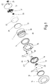
- a ceiling lamp 10 is constructed in several parts and here has a housing in the manner of a sleeve 11 with cover 12, an insulating plate 13 as a thermal barrier, an insulating layer in the form of a circumferential strip 14, a mounting ring 15 as a holder, a pot 16 as a support for an LED 17th , a lens 18, a decorative ring 19, a Cable bushing 20 with nut 21 for a hole 22 in the lid 12, screws 23 for fixing the mounting ring 15 on the underside of a fire blanket B, screws 24 for connecting the pot 16 with the mounting ring 15, screws 25 for fixing the LED 17 in the pot 16 and a screw 26 with disc 27 on.
- the sleeve 11 is made of calcium silicate (CALSITHERM) and is temperature resistant up to about 1200 degrees Celsius.
- the sleeve 11 is provided on the inside with a shoulder 28, so that an upper portion of the sleeve 12 has a smaller wall thickness than a lower portion.
- the circular insulating plate 13 is located on the peripheral shoulder 28, which is provided with a bore 29 for the passage of a cable and is preferably made of glass fiber, which is temperature resistant to about 1000 degrees Celsius or more.
- the strip 14 is preferably an intumescent agent of the Flaton Flex A type from Rex.
- the cover 12 is made of ceramic and is heat-conducting, but not electrically conductive and is glued to the front side of the sleeve 11. Preferably, an adhesive based on water glass is used.
- a board 31 is held with electronic components, not shown, for driving the LED 17, in particular glued.
- the space between the board 31 and the insulating plate 13 is filled with a foamed glass granules 32. This prevents heat transfer from the insulating plate 13 in the direction of the cover 12th
- Cable bushing 20 and nut 21 are preferably made of polyamide and temperature resistant to about 160 degrees Celsius.
- the pot 16 has a bottom 33, on which the LED 17 is fixed, and a peripheral conical wall 34, to the down / outside of a parallel to the bottom 33 directed collar 35 connects.
- the collar 35 abuts on an inner portion of the mounting ring 15. The latter rests with the inner portion at the bottom of the sleeve 11 and is glued there, preferably with an adhesive based on water glass.
- the collar 35 is bolted to the mounting ring 15, see screws 24. For this purpose, the mounting ring 15 at appropriate points corresponding thread.
- the fastening ring 15 rests with an outer portion from below on the fire blanket B and is secured there with the screws 23.
- the lens 18 is located with a peripheral edge 36 from below on the collar 35 and is glued there.
- the heat of the LED 17 (about 10 watts) and the board 31 (about 2 watts) must be dissipated.
- the heat of the LED 17 is derived via the pot 16 to the mounting ring 15 and from there into the fire blanket B.
- the heat of the board 31 is dissipated in the lid 12 and radiated from there. There are no undesirable heat esters within the ceiling light 10.
- the expanded glass granules 32 in the space between cover 12 and insulating plate 13 additionally reduces heat transfer / energy transfer from the insulating plate 13 in the direction of the cover 12, for example by rising hot air.
- the ceiling lamp designed in this way is suitable for installation in a fire protection ceiling and, together with it, meets the requirements of fire protection class B15.
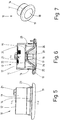
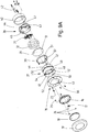
- FIGS. 9a . 9b . 9c are provided substantially the same parts or present as in the unclaimed embodiment in Fig. 1 , This is particularly clear in the comparison of Fig. 1 and 9a , Differently designed are in Fig. 9a . 9b . 9c the housing (sleeve) and the lid. Both parts are therefore in Fig. 9a . 9b . 9c with own reference numbers 37 (sleeve) and 38 (cover).
- an inner strip 39 of expanded graphite is provided, namely adjacent to the fixing ring 15.
- the lid 38 a strain relief 41 for a cable 42 is integrated.
- the lid is made of a fiber composite material, in particular of polyamide with glass fiber.
- the board 31 is glued or otherwise secured in the lid 38.
- the lid 38 is pot-shaped with a respect to the mounting position axially downwardly directed lid outer edge 43. This lies inside on an upper edge of the sleeve 37 and has downwardly directed spring tongues 44 with locking lugs 45 which in corresponding openings 46 or recesses of the sleeve 37 can engage.
- inwardly directed angle 54 are provided, each with a bore 55 for receiving a screw 56 with nut 57.
- the screw 56 also extends through a respective hole in the mounting ring 15, see also Fig. 9b ,
Landscapes
- Engineering & Computer Science (AREA)
- General Engineering & Computer Science (AREA)
- Non-Portable Lighting Devices Or Systems Thereof (AREA)
- Arrangement Of Elements, Cooling, Sealing, Or The Like Of Lighting Devices (AREA)
- Building Environments (AREA)
Description
- Die Erfindung betrifft eine Deckenleuchte zum Einbau in eine Brandschutzdecke, insbesondere an Bord von Schiffen. Daneben betrifft die Erfindung eine Brandschutzdecke.
- Brandschutzdecken, insbesondere an Bord von Schiffen, sollen im Falle eines Brandes (an einem Ort unterhalb der Brandschutzdecke) verhindern, dass Rauchgase und Wärme in den Bereich oberhalb der Brandschutzdecke gelangen können. Typischerweise besteht die Brandschutzdecke aus einer unteren, stabilen feuerfesten Lage aus Stahlblech, einer oberen stabilen feuerfesten Lage aus Stahlblech und einer mittleren, gut wärmeisolierenden Schicht aus Steinwolle.
- In die Brandschutzdecke können Deckenleuchten eingesetzt sein, sogenannte Downlights. Die Deckenleuchten strahlen Licht und Wärme nach unten ab, während elektrische Energie über Leitungen von oben zugeführt wird. Dabei unterbrechen die Deckenleuchten die Brandschutzdecke und deren Schutzfunktion.
- Moderne Deckenleuchten weisen Lichtquellen mit LEDs auf. Angesteuert werden die LEDs über elektronische Bauteile auf einer Platine. Sowohl die LEDs selbst, als auch die Platine geben im Betrieb Wärme ab. Zur Vermeidung lokaler Hitzeinseln soll die Wärme abgeführt werden.
- Die
WO 2015/046850 A1 (entsprechend der nachveröffentlichtenUS 2016/0230937 A1 ) offenbart eine Leuchte mit LED Leuchtmittel und zum Einbau in eine Decke. Mehrere LEDs sind an einem gehäuseartigen Träger gehalten. Oberhalb des Trägers ist eine glockenförmige Abdeckung vorgesehen, welche eine Platine zur Ansteuerung der Lichtquelle aufnimmt. Die Abdeckung ruht auf einer Grundplatte. Zwischen gehäuseartigem Träger und Grundplatte ist als Wärmesperre ein Hohlraum gebildet. - Die
EP 1 726 873 A1 offenbart eine feuerfeste Deckenleuchte mit einem quellfähigen Material als Füllung. - Die
EP 2 484 968 A1 offenbart einen Beleuchtungskörper als Deckenleuchte an Bord von Schiffen. Eine nicht näher dargestellte Lampeneinheit kann LEDs beinhalten. Ein glockenförmiges Gehäuseteil weist an seiner Unterseite einen umlaufenden Flansch zur Anlage an einer Decke auf, mehrere feuerfeste Beschichtungen mit wärmebeständiger Füllung zwischen zwei Schichten, und einen außenseitigen Fortsatz zur Aufnahme elektrischer Bauteile. - Die
EP 2 999 300 A1 offenbart einen Licht- und Wärmestrahler mit LED-Leuchten. Ein Mantelkern ist mit einem rieselfähigen Isolationsmaterial gefüllt. - Die
US 2012/0224381 A1 offenbart eine Leuchte mit LED-Lichtquelle, einem ersten Gehäuse zur Aufnahme der Lichtquelle und einem zweiten Gehäuse zur Aufnahme elektrischer Bauteile. Zwischen beiden Gehäusen ist eine Wärmeisolierung vorgesehen. - Die
EP 1 754 935 A1 offenbart eine feuerfeste Deckenleuchte mit einem Mantel oder einer Umhüllung, die eine metallische Schicht und eine feuerfeste Schicht beinhalten kann. - Die
DE 81 07 035 U1 offenbart eine von einem Feuerschutzkasten umschlossene Deckeneinbauleuchte, etwa für Brandschutzdecken. Seitenwände des Feuerschutzkastens sind Formteile aus hochfestem keramischem Fasermaterial. - Die
US 2008/0165545 A1 offenbart eine Deckenleuchte mit Feuerschutzkasten, wobei eine Anschlussdose außerhalb des Feuerschutzkastens vorgesehen ist. - Die
US 2008/0170404 A1 offenbart eine feuerfeste Deckenleuchte mit Feuerschutzkasten, welcher ein quellfähiges Material enthalten kann. - Aufgabe der vorliegenden Erfindung ist die Schaffung einer Deckenleuchte zum Einbau in eine Brandschutzdecke, wobei die Schutzfunktion der Brandschutzdecke aufrechterhalten wird. Außerdem soll eine gute Wärmeabfuhr im Betrieb gewährleistet sein.
- Zur Lösung der Aufgabe weist die erfindungsgemäße Deckenleuchte die Merkmale des Anspruchs 1 auf, insbesondere:
- a) eine LED-Lichtquelle ist an einem Träger gehalten,
- b) der Träger ist zumindest mittelbar zur Anlage an der Brandschutzdecke vorgesehen,
- c) ein Gehäuse ist zumindest mittelbar mit dem Träger verbunden und nimmt eine Platine zur Ansteuerung der LED-Lichtquelle auf,
- d) das Gehäuse weist zwischen der Platine und dem Träger eine Wärmesperre auf,
- e) das metallische Wandungen aufweisende oder beinhaltende Gehäuse ist unterteilt in einen oberen Abschnitt (47) zur Aufnahme der Platine (31) und einen unteren Abschnitt (48) zur Aufnahme des Trägers mit der LED-Lichtquelle (17), wobei oberer Abschnitt (47) und unterer Abschnitt (48) nur durch Stege (49, 50) miteinander verbunden sind, sodass gegenüber einer vollflächigen Verbindung der Abschnitte (47, 48) nur eine reduzierte Wärmeleitung möglich ist, nämlich im Bereich der Stege (49, 50).
- LED-Lichtquelle und Träger sind wärmeleitend miteinander verbunden. Der Träger leitet die Wärme der LED-Lichtquelle nach außen ab in Richtung auf die Brandschutzdecke.
- Die Wärmesperre über dem Träger verhindert einen Wärmedurchgang von der Unterseite der Deckenleute zur Oberseite derselben. Dadurch wird auch die Platine vor zu großer Hitze und dem Erreichen einer kritischen Temperatur geschützt. Das Gehäuse besteht insbesondere, ebenso wie die Wärmesperre, aus einem wärmedämmenden Werkstoff.
- Die metallischen Wandungen weisen insbesondere einen höheren Schmelzpunkt als Aluminium auf. Die metallischen Wandungen leiten im Brandfall Wärme relativ gut. Zur Verminderung der Wärmeleitung sind die metallischen Wandungen zwischen dem unteren und dem oberen Abschnitt unterbrochen durch Ausnehmungen. Zwischen den Ausnehmungen sind Stege gebildet, welche als Verbindung zwischen den Abschnitten ausreichen und die eine deutlich geringere Wärmeleitung als vollflächige Wandungen bedingen.
- Vorteilhafterweise erstreckt sich das Gehäuse bis über die Brandschutzdecke. Entsprechend kann das Gehäuse nach oben aus der Brandschutzdecke herausragen. Nach einem weiteren Gedanken der Erfindung ist vorgesehen, dass der Träger aus Aluminium bzw, einer üblichen AlMg-Legierung hergestellt ist und/oder eine Wärmeleitfähigkeit von etwa 150 W/(mK) oder mehr aufweist. Dadurch ist auch eine hohe LED-Wärmeleistung abführbar. Im Brandfall schmilzt der Träger aus Aluminium spätestens bei etwa 650 Grad Celsius. Bei geringerer LED-Wärmeleistung kann der Träger auch aus Stahl oder anderen Werkstoffen mit etwas geringerer Wärmeleitfähigkeit aber vorzugsweise höherer Feuerfestigkeit als Aluminium bestehen.
- Nach einem weiteren Gedanken der Erfindung weist das Gehäuse außenseitig umlaufend einen Dämmschichtbildner auf. Vorzugsweise handelt es sich um einen ringförmig um das Gehäuse umlaufenden Streifen aus einem unter Hitzeeinwirkung aufquellenden Werkstoff. Werkstoffe mit derartigen Eigenschaften sind grundsätzlich bekannt. Die Volumenvergrößerung des Streifens tritt vorzugsweise bei Temperaturen oberhalb von 150 Grad Celsius auf und erfolgt mit einem Faktor von insbesondere 10 bis 20.
- Nach einem weiteren Gedanken der Erfindung weist das Gehäuse eine hülsenförmig umlaufende Wandung auf. Die umlaufende Wandung kann mit einem Deckel versehen sein.
- Vorteilhafterweise ist das Gehäuse mit Wandungen aus Kalziumsilikat versehen. Insbesondere bestehen die Wandungen aus einem Werkstoff, der unter der Marke CALSITHERM vertrieben wird.
- Nach einem weiteren Gedanken der Erfindung ist die Platine an einer wärmeleitenden Platte gehalten. Vorzugsweise ist die Platine an einer Innenseite der Platte angeordnet und liegt dort an. Die wärmeleitende Platte soll die im Betrieb entstehende Wärme der Platine ableiten bzw. verteilen. Die aufgenommene Wärme kann von der Platte nach oben bzw. außen abgestrahlt werden.
- Nach einem weiteren Gedanken der Erfindung bildet die wärmeleitende Platte einen Deckel für das Gehäuse und ist mit diesem vorzugsweise verklebt. Als Kleber ist insbesondere ein Kleber auf Basis von Wasserglas vorgesehen.
- Nach einem weiteren Gedanken der Erfindung ist die wärmeleitende Platte ein schlechter elektrischer Leiter und/oder besteht aus einem keramischen Werkstoff. Eine zusätzliche elektrische Isolierung soll nicht erforderlich sein. Keramik leitet zwar schlechter Wärme als Aluminium oder Stahl. Für die Wärmeabfuhr der Platine genügt dies aber.
- Nach einem weiteren Gedanken der Erfindung besteht die Wärmesperre aus Glasseide und/oder ist eine Platte innerhalb des Gehäuses. Vorzugsweise ist im Inneren des Gehäuses ein umlaufender Absatz vorgesehen, auf dem die Wärmesperre zu liegen kommt. Die Wärmesperre ist ein schlechter Wärmeleiter, ebenso wie das Gehäuse.
- Nach einem weiteren Gedanken der Erfindung ist zwischen der Wärmesperre und der Platine ein Raum vorgesehen, welcher zumindest teilweise durch ein Blähglasgranulat ausgefüllt ist. Die Wärmesperre kann aber selbst noch eine zu hohe Temperatur annehmen. Entsprechend kann Wärme durch Konvektion an die Luft oberhalb der Wärmesperre abgegeben werden. Die Luft kann die Elektronikplatine und/oder die wärmeleitende Platte erhitzen. Das vorgesehene Blähglasgranulat verringert die beschriebene Wärmeübertragung deutlich.
- Nach einem weiteren Gedanken der Erfindung ist der Träger topfförmig ausgebildet, insbesondere mit einer konischen Wandung und mit einem Boden. Die Wärme der am Boden anliegenden LED wird im Betrieb flächig nach außen/unten abgeleitet.
- Nach einem weiteren Gedanken der Erfindung ist der Träger mit einem Halter verbunden ist, welcher eine höhere Temperaturbeständigkeit als der Träger aufweist, wobei der Halter zur Anlage an der Brandschutzdecke vorgesehen ist. Der Halter soll die Verbindung zur Brandschutzdecke auch bei hohen Temperaturen sicherstellen, insbesondere bei 800 Grad Celsius oder mehr. Demgegenüber kann der Träger bei dieser Temperatur schon abgeschmolzen sein.
- Nach einem weiteren Gedanken der Erfindung ist der Halter mit dem Gehäuse verbunden ist. Vorzugsweise dichtet der Halter wenigstens im Normalbetrieb einen Übergang zwischen Deckenleuchte/Gehäuse und Brandschutzdecke ab. Der Träger liegt vorzugsweise von unten auf dem Halter auf.
- Nach einem weiteren Gedanken der Erfindung ist vorgesehen, dass der Halter aus Stahl hergestellt ist und/oder eine Wärmeleitfähigkeit von 15 bis 100 W/(mK), insbesondere von etwa 50 W/(mK) aufweist. Ziel ist eine hohe Stabilität des Halters auch bei hohen Temperaturen. Stahlblech ist noch bei etwa 1300 Grad Celsius fest.
- Nach einem weiteren Gedanken der Erfindung ist, dass der Halter ringförmig ausgebildet ist, insbesondere als Befestigungsring (15), und/oder dass der Halter flächig zur Anlage an der Brandschutzdecke ausgebildet ist. Als flacher Ring kann der Halter an der Brandschutzdecke anliegen, ebenso am Gehäuse, und so im Betrieb die Wärme der LED vom Träger abführen. Zugleich ist der Übergang zwischen Gehäuse und Brandschutzdecke vollständig abgedeckt.
- Nach einem weiteren Gedanken der Erfindung weist das Gehäuse eine Wärmeleitfähigkeit von etwa 0,3 W/(mK) oder weniger auf, insbesondere 0,05 W/(mK) oder weniger. Wärmesperre, Blähglasgranulat und/oder Dämmschichtbildner weisen eine Wärmeleitfähigkeit von insbesondere 0,05 W/(mK) oder weniger auf.
- Nach einem weiteren Gedanken der Erfindung weist das Gehäuse Wandungen aus Stahl auf oder beinhaltet diese, insbesondere aus Edelstahl.
- Nach einem weiteren Gedanken der Erfindung ist das Gehäuse im Bereich des oberen Abschnitts außenseitig mit einem Dämmschichtbildner versehen, insbesondere mit einem Streifen aus Blähgraphit. Alternativ oder zusätzlich ist das Gehäuse im Bereich des unteren Abschnitts innenseitig mit einem Dämmschichtbildner versehen, insbesondere mit einem Streifen aus Blähgraphit. Im oberen Bereich erstreckt sich der Dämmschichtbildner bzw. Streifen bis über die Wärmesperre herab (vorzugsweise) bzw. bis auf den unteren Abschnitt, sodass Stege zur Verbindung der Abschnitte abgedeckt sind. Dämmschichtbildner bzw. Streifen des unteren Abschnitts liegen vorzugsweise am Träger oder einem Halter hierfür an.
- Nach einem weiteren Gedanken der Erfindung weist das Gehäuse innenseitig Halter oder Lager für die Wärmesperre auf. Vorzugsweise sind die Lager oder Halter im Bereich zwischen einem oberen und einem unteren Abschnitt, insbesondere im Bereich von Stegen zwischen den Abschnitten vorgesehen. Die Halter oder Lager können bei einem Gehäuse aus Metallblech durch Stanzen und Umbiegen von kleinen zungenartigen Bereichen gebildet werden.
- Nach einem weiteren Gedanken der Erfindung weist das Gehäuse oberseitig einen Deckel auf, auf dem innenseitig die Platine gehalten ist. Der Deckel kann mit einer integrierten Zugentlastung und einer Bohrung für ein Kabel versehen sein. Vorzugsweise sitzt ein Deckelaußenrand innen in einem oberen Abschnitt des Gehäuses. Dabei kann der Deckelaußenrand abwärts gerichtet sein. Oberer Abschnitt des Gehäuses und Deckelaußenrand weisen vorzugsweise korrespondierende Vorsprünge und Vertiefungen auf, um eine gesicherte Relativposition nach Montage des Deckels zu halten. Die Vorsprünge und/oder Vertiefungen können auch an federnden Zungen vorgesehen sein, sodass bei der Montage des Deckels entsprechende Verbindungen durch Federdruck einschnappen. Vorzugsweise ist der Deckel aus einem Faserverbundwerkstoff hergestellt, insbesondere aus Polyamid mit Glasfaser.
- Eine erfindungsgemäße Brandschutzdecke weist wenigstens eine Deckenleuchte wie voranstehend beschrieben auf. Insbesondere ist die Brandschutzdecke mit oberem Deckenblech, unterem Deckenblech und Steinwolle zwischen den Deckenblechen versehen.
- Insgesamt soll die Kombination aus Deckenleute und Brandschutzdecke vorzugsweise die Anforderungen an die Brandschutzklasse B15 erfüllen.
- Weitere Merkmale der Erfindung ergeben sich aus der Beschreibung im Übrigen und aus den Ansprüchen. Vorteilhafte Ausführungsformen der Erfindung werden nachfolgend anhand von Zeichnungen näher erläutert. Es zeigen:
- Fig. 1
- eine Explosionsdarstellung einer nicht beanspruchten Deckenleuchte,
- Fig. 2
- eine Unteransicht der Deckenleuchte gemäß
Fig. 1 , - Fig. 3
- einen Schnitt durch die Deckenleuchte entlang der Linie A-A in
Fig. 2 , - Fig. 4
- einen Schnitt durch die Deckenleuchte entlang der Linie B-B in
Fig. 2 , - Fig. 5
- eine Seitenansicht der Deckenleuchte gemäß
Fig. 1 , - Fig. 6
- einen Schnitt durch die Deckenleuchte entlang der Linie C-C in
Fig. 5 , - Fig. 7
- eine perspektivische Darstellung der Deckenleuchte gemäß
Fig. 1 , - Fig. 8
- die Seitenansicht gemäß
Fig. 5 , mit Brandschutzdecke, - Fig. 9a
- eine Explosionsdarstellung einer beanspruchten Ausführungsform der Deckenleuchte,
- Fig. 9b
- einen Schnitt durch die Deckenleuchte gemäß
Fig. 9a , - Fig. 9c
- einen um 90 Grad versetzten Schnitt durch die Deckenleuchte gemäß
Fig. 9b . - Eine Deckenleuchte 10 ist mehrteilig aufgebaut und weist hier ein Gehäuse nach Art einer Hülse 11 mit Deckel 12, eine Isolierplatte 13 als Wärmesperre, einen Dämmschichtbildner in Gestalt eines umlaufenden Streifens 14, einen Befestigungsring 15 als Halter, einen Topf 16 als Träger für eine LED 17, eine Linse 18, einen Dekorring 19, eine Kabeldurchführung 20 mit Mutter 21 für eine Bohrung 22 im Deckel 12, Schrauben 23 zur Befestigung des Befestigungsrings 15 an der Unterseite einer Brandschutzdecke B, Schrauben 24 zur Verbindung des Topfes 16 mit dem Befestigungsring 15, Schrauben 25 zur Fixierung der LED 17 im Topf 16 und eine Schraube 26 mit Scheibe 27 auf.
- Die Hülse 11 besteht aus Kalziumsilikat (CALSITHERM) und ist bis etwa 1200 Grad Celsius temperaturbeständig. Dabei ist die Hülse 11 innenseitig mit einem Absatz 28 versehen, so dass ein oberer Abschnitt der Hülse 12 eine geringere Wandstärke aufweist als ein unterer Abschnitt. Auf dem umlaufenden Absatz 28 liegt die kreisförmige Isolierplatte 13 auf. Diese ist mit einer Bohrung 29 zur Durchführung eines Kabels versehen und besteht vorzugsweise aus Glasseide, welche temperaturbeständig ist bis etwa 1000 Grad Celsius oder mehr.
- Im unteren Abschnitt ist die Hülse 11 mit einer außen umlaufenden Nut 30 zur Aufnahme des Streifens 14 versehen, welcher bei einer Temperatur oberhalb von 150 Grad Celsius sein Volumen um den Faktor 10 bis 20 vergrößert. Dadurch wird im Brandfall eine wirksame Rauchsperre mit der umgebenden Brandschutzdecke B gebildet. Bei dem Streifen 14 handelt es sich vorzugsweise um einen Dämmschichtbildner des Typs Flaton Flex A von der Firma Rex.
- Der Deckel 12 besteht aus Keramik und ist wärmeleitend, jedoch nicht elektrisch leitend und ist stirnseitig mit der Hülse 11 verklebt. Vorzugsweise wird ein Kleber auf der Basis von Wasserglas verwendet. An der Unterseite des Deckels 12 ist eine Platine 31 mit nicht gezeigten elektronischen Bauteilen zur Ansteuerung der LED 17 gehalten, insbesondere verklebt. Der Raum zwischen der Platine 31 und der Isolierplatte 13 ist mit einem Blähglasgranulat 32 gefüllt. Dieses verhindert eine Wärmeübertragung von der Isolierplatte 13 in Richtung auf den Deckel 12.
- Kabeldurchführung 20 und Mutter 21 sind vorzugsweise aus Polyamid hergestellt und temperaturbeständig bis etwa 160 Grad Celsius.
- Der Topf 16 weist einen Boden 33 auf, auf dem die LED 17 befestigt ist, sowie eine umlaufende konische Wandung 34, an die nach unten/außen ein parallel zum Boden 33 gerichteter Kragen 35 anschließt. Der Kragen 35 liegt auf einem inneren Abschnitt des Befestigungsrings 15 an. Letzterer liegt mit dem inneren Abschnitt unten an der Hülse 11 an und ist dort verklebt, vorzugsweise mit einem Kleber auf der Basis von Wasserglas. Der Kragen 35 ist mit dem Befestigungsring 15 verschraubt, siehe Schrauben 24. Hierzu weist der Befestigungsring 15 an geeigneten Stellen entsprechende Gewinde auf.
- Der Befestigungsring 15 liegt mit einem äußeren Abschnitt von unten an der Brandschutzdecke B an und ist dort mit den Schrauben 23 gesichert.
- Die Linse 18 liegt mit einem umlaufenden Rand 36 von unten auf dem Kragen 35 und ist dort verklebt.
- Im Normalbetrieb müssen die Wärme der LED 17 (etwa 10 Watt) und der Platine 31 (etwa 2 Watt) abgeführt werden. Die Wärme der LED 17 wird über den Topf 16 zum Befestigungsring 15 und von dort in die Brandschutzdecke B abgeleitet. Die Wärme der Platine 31 wird in den Deckel 12 abgeleitet und von dort abgestrahlt. Es bilden sich keine unerwünschten Wärmenester innerhalb der Deckenleuchte 10.
- Im Brandfall, bei sehr starker Hitzeentwicklung schmelzen die Linse 18 aus Kunststoff, der Topf 16 aus Aluminium (mit LED) und der Dekorring 19 ab, während der Befestigungsring 15 aus Stahl zusammen mit der Hülse 11 stabil bleibt. Das heißt, die Verbindung zur Brandschutzdecke B bleibt erhalten. Allerdings kann sich der Befestigungsring 15 verziehen und heiße Rauchgase nach oben passieren lassen. Dem wirkt die Dämmschichtbildung durch den Streifen 14 entgegen. Außerdem verhindert die Isolierplatte 13 einen übermäßigen Wärmetransfer nach oben in Richtung auf die Platine 31.
- Platine 31 und Deckel 12 sind durch einen Silikonkleber miteinander verklebt. Auch sind durch die Kabeldurchführung 20 hindurchgeführte Kabel mit Silikon isoliert.
- Das Blähglasgranulat 32 im Raum zwischen Deckel 12 und Isolierplatte 13 vermindert zusätzlich einen Wärmetransport / Energietransfer von der Isolierplatte 13 in Richtung auf den Deckel 12, etwa durch aufsteigende heiße Luft.
- Die derart gestaltete Deckenleuchte ist zum Einbau in eine Brandschutzdecke geeignet und erfüllt zusammen mit dieser die Anforderungen der Brandschutzklasse B15.
- In der Ausführungsform der
Figuren 9a ,9b ,9c sind im Wesentlichen die gleichen Teile vorgesehen bzw. vorhanden wie im nicht beanspruchten Ausführungsbeispiel inFig. 1 . Deutlich wird dies insbesondere im Vergleich derFig. 1 und9a . Anders gestaltet sind inFig. 9a ,9b ,9c das Gehäuse (Hülse) und der Deckel. Beide Teile sind deshalb inFig. 9a ,9b ,9c mit eigenen Bezugsziffern 37 (Hülse) und 38 (Deckel) versehen. Außerdem ist anstelle des außen liegenden Streifens 14 ein innen liegender Streifen 39 aus Blähgraphit vorgesehen, nämlich an den Befestigungsring 15 angrenzend. Zusätzlich ist ein außen liegender Streifen 40 aus Blähgraphit vorhanden, der sich von einer Position oberhalb der Brandschutzdecke B, nämlich etwa vom Deckel 38, bis zur Isolierplatte 13 (Wärmesperre) erstreckt, somit etwa über die halbe Höhe der Hülse 37 oder etwas mehr. Demgegenüber erstreckt sich der innen liegende Streifen 39 nur über etwa 1/5 der Höhe der Hülse 37, ausgehend vom Befestigungsring 15. - In den Deckel 38 ist eine Zugentlastung 41 für ein Kabel 42 integriert. Vorzugsweise ist der Deckel aus einem Faserverbundwerkstoff hergestellt, insbesondere aus Polyamid mit Glasfaser. Innenseitig ist in den Deckel 38 die Platine 31 eingeklebt oder auf andere Weise befestigt.
- Der Deckel 38 ist topfartig ausgebildet mit einem in Bezug auf die Einbaulage axial abwärts gerichteten Deckelaußenrand 43. Dieser liegt innen an einem oberen Rand der Hülse 37 an und weist abwärts gerichtete Federzungen 44 mit Rastnasen 45 auf, die in entsprechende Öffnungen 46 oder Vertiefungen der Hülse 37 einrasten können.
- Die Hülse 37 bildet den Hauptbestandteil des Gehäuses und besteht hier aus einem Metall mit höherem Schmelzpunkt als Aluminium, insbesondere aus Edelstahl oder einem anderen Stahl. Im Brandfall könnte die entstehende Hitze relativ gut entlang der Hülse 37 durch Wärmeleitung transportiert werden. Stark reduziert wird die Wärmeleitung durch zwei konstruktive Maßnahmen. Zum einen ist die Wandung der Hülse 37 relativ dünn und beträgt vorzugsweise nur etwa 0,5 mm. Zum anderen ist die Hülse 37 unterteilt in einen oberen Abschnitt 47 und einen unteren Abschnitt 48, welche nur über schmale Stege 49 in Axialrichtung und Stege 50 in Umfangsrichtung miteinander verbunden sind. Die Stege 49, 50 sind hier gebildet durch entsprechend gestaltete und angeordnete Schlitze 51, welche in Umfangsrichtung verlaufen.
- Der dem oberen Abschnitt 47 zugeordnete Streifen 40 erstreckt sich abwärts bis über die Stege 49, 50 und Schlitze 51.
- Als Lager für die Isolierplatte 13 weist die Hülse 37 im Bereich der Schlitze 51, zwischen zwei Stegen 49, einwärts gerichtete Winkel 52 auf, auf denen die Isolierplatte 13 aufliegt. Winkel 52, Schlitze 51, Stege 29, 50 und Öffnungen 46 liegen im Bereich eines Übergangs zwischen dem oberen Abschnitt 47 und dem unteren Abschnitt 48.
- An einem unteren Rand 53 der Hülse 37 sind einwärts gerichtete Winkel 54 vorgesehen, jeweils mit einer Bohrung 55 zur Aufnahme einer Schraube 56 mit Mutter 57. Dabei erstreckt sich die Schraube 56 jeweils auch durch eine entsprechende Bohrung im Befestigungsring 15, siehe auch
Fig. 9b .
Claims (15)
- Deckenleuchte (10) zum Einbau in eine Brandschutzdecke, insbesondere an Bord von Schiffen, mit folgenden Merkmalen:a) eine LED-Lichtquelle (17) ist an einem Träger gehalten,b) der Träger ist zumindest mittelbar zur Anlage an der Brandschutzdecke vorgesehen,c) ein Gehäuse ist zumindest mittelbar mit dem Träger verbunden und nimmt eine Platine (31) zur Ansteuerung der LED-Lichtquelle (17) auf,d) das Gehäuse weist zwischen der Platine (31) und dem Träger eine Wärmesperre auf,e) das metallische Wandungen aufweisende oder beinhaltende Gehäuse ist unterteilt in einen oberen Abschnitt (47) zur Aufnahme der Platine (31) und einen unteren Abschnitt (48) zur Aufnahme des Trägers mit der LED-Lichtquelle (17), wobei oberer Abschnitt (47) und unterer Abschnitt (48) nur durch Stege (49, 50) miteinander verbunden sind, sodass gegenüber einer vollflächigen Verbindung der Abschnitte (47, 48) nur eine reduzierte Wärmeleitung möglich ist, nämlich im Bereich der Stege (49, 50).
- Deckenleuchte nach Anspruch 1, dadurch gekennzeichnet, dass der Träger aus Aluminium hergestellt ist und/oder eine Wärmeleitfähigkeit von etwa 150 W/(mK) oder mehr aufweist.
- Deckenleuchte nach Anspruch 1 oder 2, dadurch gekennzeichnet, dass das Gehäuse außenseitig umlaufend einen Dämmschichtbildner aufweist und/oder dass das Gehäuse selbst wärmedämmend ausgebildet ist.
- Deckenleuchte nach Anspruch 1 oder einem der weiteren Ansprüche, dadurch gekennzeichnet, dass das Gehäuse nach Art einer Hülse (11) mit umlaufender Wandung ausgebildet ist.
- Deckenleuchte nach Anspruch 1 oder einem der weiteren Ansprüche, dadurch gekennzeichnet, dass das Gehäuse Wandungen aus Kalziumsilikat aufweist.
- Deckenleuchte nach Anspruch 1 oder einem der weiteren Ansprüche, dadurch gekennzeichnet, dass die Platine (31) an einer wärmeleitenden Platte gehalten ist, und dass die wärmeleitende Platte vorzugsweise einen Deckel (12) für das Gehäuse bildet und mit der Platine (31) insbesondere verklebt ist.
- Deckenleuchte nach Anspruch 1 oder einem der weiteren Ansprüche, dadurch gekennzeichnet, dass die Wärmesperre aus Glasseide besteht und/oder eine Platte innerhalb des Gehäuses ist.
- Deckenleuchte nach Anspruch 1 oder einem der weiteren Ansprüche, dadurch gekennzeichnet, dass zwischen der Wärmesperre und der Platine (31) ein Raum vorgesehen ist, welcher zumindest teilweise durch ein Blähglasgranulat (32) ausgefüllt ist.
- Deckenleuchte nach Anspruch 1 oder einem der weiteren Ansprüche, dadurch gekennzeichnet, dass der Träger mit einem Halter verbunden ist, welcher eine höhere Temperaturbeständigkeit als der Träger aufweist, wobei der Halter zur Anlage an der Brandschutzdecke vorgesehen ist.
- Deckenleuchte nach Anspruch 9, dadurch gekennzeichnet, dass der Halter mit dem Gehäuse verbunden ist.
- Deckenleuchte nach Anspruch 1 oder einem der weiteren Ansprüche, dadurch gekennzeichnet, dass Wärmesperre, Gehäuse und/oder Dämmschichtbildner eine Wärmeleitfähigkeit von 0,2 W/(mK) oder weniger aufweisen, insbesondere 0,05 W/(mK) oder weniger.
- Deckenleuchte nach Anspruch 1 oder einem der weiteren Ansprüche, dadurch gekennzeichnet, dass das Gehäuse Wandungen aus Stahl, insbesondere Edelstahl, aufweist oder beinhaltet.
- Deckenleuchte nach Anspruch 1 oder einem der weiteren Ansprüche, dadurch gekennzeichnet, dass das Gehäuse im Bereich des oberen Abschnitts (47) außenseitig mit einem Dämmschichtbildner versehen ist, insbesondere mit einem Streifen (40) aus Blähgraphit, und/oder dass das Gehäuse im Bereich des unteren Abschnitts (48) innenseitig mit einem Dämmschichtbildner versehen ist, insbesondere mit einem Streifen (39) aus Blähgraphit.
- Deckenleuchte nach Anspruch 1 oder einem der weiteren Ansprüche, dadurch gekennzeichnet, dass das Gehäuse oberseitig einen Deckel (38) aufweist, auf dem innenseitig die Platine (31) gehalten ist, wobei der Deckel (38) vorzugsweise aus einem Faserverbundwerkstoff, insbesondere aus Polyamid mit Glasfaser hergestellt ist, und wobei der Deckel (38) vorzugsweise einen abwärts gerichteten Deckelaußenrand (43) aufweist.
- Brandschutzdecke mit wenigstens einer Deckenleuchte nach einem der voranstehenden Ansprüche.
Applications Claiming Priority (1)
| Application Number | Priority Date | Filing Date | Title |
|---|---|---|---|
| DE102016006422.6A DE102016006422A1 (de) | 2016-05-23 | 2016-05-23 | Deckenleuchte zum Einbau in eine Brandschutzdecke |
Publications (2)
| Publication Number | Publication Date |
|---|---|
| EP3249291A1 EP3249291A1 (de) | 2017-11-29 |
| EP3249291B1 true EP3249291B1 (de) | 2019-01-23 |
Family
ID=58668699
Family Applications (1)
| Application Number | Title | Priority Date | Filing Date |
|---|---|---|---|
| EP17000704.1A Not-in-force EP3249291B1 (de) | 2016-05-23 | 2017-04-25 | Deckenleuchte zum einbau in eine brandschutzdecke |
Country Status (2)
| Country | Link |
|---|---|
| EP (1) | EP3249291B1 (de) |
| DE (1) | DE102016006422A1 (de) |
Family Cites Families (9)
| Publication number | Priority date | Publication date | Assignee | Title |
|---|---|---|---|---|
| DE8107035U1 (de) * | 1981-03-12 | 1981-07-30 | Dipl.-Ing. Schaer-Lüderitz GmbH, 4990 Lübbecke | Von einem feuerschutzkasten umschlossene deckeneinbauleuchte, insbes. fuer abgehaengte decken |
| JP3136127U (ja) * | 2004-06-09 | 2007-10-18 | リャンジュ ウ | 火災防止型組込み式照明器具 |
| GB0510494D0 (en) * | 2005-05-23 | 2005-06-29 | Aurora Ltd | Improvements to fire related downlights |
| US7651238B2 (en) * | 2007-01-10 | 2010-01-26 | O'brien Aaron | Fireproof trim and insulated lighting assembly |
| US7670033B2 (en) * | 2007-01-11 | 2010-03-02 | Tenmat Ltd. | Fire stop for light fixture |
| CN102725579B (zh) * | 2011-01-27 | 2015-09-23 | 松下知识产权经营株式会社 | 光源装置 |
| GB201102129D0 (en) * | 2011-02-08 | 2011-03-23 | Jones Peter C | Recessed light fitting |
| KR20150033234A (ko) * | 2013-09-24 | 2015-04-01 | 엘지이노텍 주식회사 | 조명 장치 |
| AT515422B1 (de) * | 2014-09-18 | 2015-09-15 | Redwell Manufaktur Gmbh | Licht- und Wärmestrahler |
-
2016
- 2016-05-23 DE DE102016006422.6A patent/DE102016006422A1/de not_active Withdrawn
-
2017
- 2017-04-25 EP EP17000704.1A patent/EP3249291B1/de not_active Not-in-force
Non-Patent Citations (1)
| Title |
|---|
| None * |
Also Published As
| Publication number | Publication date |
|---|---|
| EP3249291A1 (de) | 2017-11-29 |
| DE102016006422A1 (de) | 2017-11-23 |
Similar Documents
| Publication | Publication Date | Title |
|---|---|---|
| DE112012001537B4 (de) | Leuchtdioden-Strahler | |
| EP2671434B1 (de) | Elektrisches gerät | |
| EP2451710B1 (de) | Beleuchtungsvorrichtung für flughäfen | |
| DE102013225411B4 (de) | Verbinder für eine LED-Modulplatine und Kombination aus Verbinder und LED- Modulplatine | |
| EP2487411B1 (de) | Kühlkörper für LED-Leuchte | |
| DE10247828B4 (de) | Wärmeableitendes und -abstrahlendes Kuststoffgehäuse mit Kühl-/Tragrippen und umpritztem Kühlkörper und Verfahren zu dessen Fertigung | |
| EP3249291B1 (de) | Deckenleuchte zum einbau in eine brandschutzdecke | |
| DE102008039071B4 (de) | Beleuchtungsvorrichtung für Fahrzeuge | |
| EP3044506B1 (de) | Explosionsgeschützte leuchte | |
| DE202012005765U1 (de) | LED-Einbauleuchte | |
| DE102008001066B4 (de) | Kühlvorrichtung zur Kühlung von LED-Lichtquellen | |
| EP2442020A2 (de) | Leuchte mit schwenkbarer, flacher Leuchteinheit | |
| DE202009005266U1 (de) | LED-Lampe mit hoher Wärmeabführleistung und Sicherheit | |
| EP3671035B1 (de) | Leuchte mit kühlrippen im leuchtengehäuse | |
| EP2085692B1 (de) | Elektrische Schaltungsanordnung, insbesondere Signalleuchte | |
| DE202014105429U1 (de) | Einbauleuchte | |
| DE202008007238U1 (de) | Beleuchtungseinrichtung | |
| EP3118518B1 (de) | Leuchtengehäuse | |
| EP2581657B1 (de) | Kühlkörper-Anordnung für eine LED-Leuchte sowie LED-Leuchte | |
| WO2010142490A1 (de) | Formteil zur aufnahme mehrerer elektrischer bauteile | |
| DE102013207596B4 (de) | Leuchtmittel mit Trägereinrichtung | |
| EP2757316B1 (de) | Leuchtenkörper | |
| DE102016100097A1 (de) | Leuchtenbaugruppe mit einem Gehäuseelement und einem Leuchtmittel-Modul | |
| DE102009019272B4 (de) | Temperaturstabilisierte Kollimator-Lichtquelle | |
| DE102015117165B4 (de) | Elektrantenauslass bei Doppelböden |
Legal Events
| Date | Code | Title | Description |
|---|---|---|---|
| PUAI | Public reference made under article 153(3) epc to a published international application that has entered the european phase |
Free format text: ORIGINAL CODE: 0009012 |
|
| STAA | Information on the status of an ep patent application or granted ep patent |
Free format text: STATUS: THE APPLICATION HAS BEEN PUBLISHED |
|
| AK | Designated contracting states |
Kind code of ref document: A1 Designated state(s): AL AT BE BG CH CY CZ DE DK EE ES FI FR GB GR HR HU IE IS IT LI LT LU LV MC MK MT NL NO PL PT RO RS SE SI SK SM TR |
|
| AX | Request for extension of the european patent |
Extension state: BA ME |
|
| STAA | Information on the status of an ep patent application or granted ep patent |
Free format text: STATUS: REQUEST FOR EXAMINATION WAS MADE |
|
| 17P | Request for examination filed |
Effective date: 20180522 |
|
| RBV | Designated contracting states (corrected) |
Designated state(s): AL AT BE BG CH CY CZ DE DK EE ES FI FR GB GR HR HU IE IS IT LI LT LU LV MC MK MT NL NO PL PT RO RS SE SI SK SM TR |
|
| GRAP | Despatch of communication of intention to grant a patent |
Free format text: ORIGINAL CODE: EPIDOSNIGR1 |
|
| STAA | Information on the status of an ep patent application or granted ep patent |
Free format text: STATUS: GRANT OF PATENT IS INTENDED |
|
| INTG | Intention to grant announced |
Effective date: 20180912 |
|
| GRAS | Grant fee paid |
Free format text: ORIGINAL CODE: EPIDOSNIGR3 |
|
| GRAA | (expected) grant |
Free format text: ORIGINAL CODE: 0009210 |
|
| STAA | Information on the status of an ep patent application or granted ep patent |
Free format text: STATUS: THE PATENT HAS BEEN GRANTED |
|
| AK | Designated contracting states |
Kind code of ref document: B1 Designated state(s): AL AT BE BG CH CY CZ DE DK EE ES FI FR GB GR HR HU IE IS IT LI LT LU LV MC MK MT NL NO PL PT RO RS SE SI SK SM TR |
|
| REG | Reference to a national code |
Ref country code: GB Ref legal event code: FG4D Free format text: NOT ENGLISH |
|
| REG | Reference to a national code |
Ref country code: CH Ref legal event code: EP |
|
| REG | Reference to a national code |
Ref country code: AT Ref legal event code: REF Ref document number: 1091737 Country of ref document: AT Kind code of ref document: T Effective date: 20190215 |
|
| REG | Reference to a national code |
Ref country code: IE Ref legal event code: FG4D Free format text: LANGUAGE OF EP DOCUMENT: GERMAN |
|
| REG | Reference to a national code |
Ref country code: DE Ref legal event code: R096 Ref document number: 502017000657 Country of ref document: DE |
|
| REG | Reference to a national code |
Ref country code: NO Ref legal event code: T2 Effective date: 20190123 |
|
| REG | Reference to a national code |
Ref country code: NL Ref legal event code: MP Effective date: 20190123 |
|
| PG25 | Lapsed in a contracting state [announced via postgrant information from national office to epo] |
Ref country code: NL Free format text: LAPSE BECAUSE OF FAILURE TO SUBMIT A TRANSLATION OF THE DESCRIPTION OR TO PAY THE FEE WITHIN THE PRESCRIBED TIME-LIMIT Effective date: 20190123 |
|
| PG25 | Lapsed in a contracting state [announced via postgrant information from national office to epo] |
Ref country code: PT Free format text: LAPSE BECAUSE OF FAILURE TO SUBMIT A TRANSLATION OF THE DESCRIPTION OR TO PAY THE FEE WITHIN THE PRESCRIBED TIME-LIMIT Effective date: 20190523 Ref country code: SE Free format text: LAPSE BECAUSE OF FAILURE TO SUBMIT A TRANSLATION OF THE DESCRIPTION OR TO PAY THE FEE WITHIN THE PRESCRIBED TIME-LIMIT Effective date: 20190123 Ref country code: PL Free format text: LAPSE BECAUSE OF FAILURE TO SUBMIT A TRANSLATION OF THE DESCRIPTION OR TO PAY THE FEE WITHIN THE PRESCRIBED TIME-LIMIT Effective date: 20190123 Ref country code: ES Free format text: LAPSE BECAUSE OF FAILURE TO SUBMIT A TRANSLATION OF THE DESCRIPTION OR TO PAY THE FEE WITHIN THE PRESCRIBED TIME-LIMIT Effective date: 20190123 Ref country code: LT Free format text: LAPSE BECAUSE OF FAILURE TO SUBMIT A TRANSLATION OF THE DESCRIPTION OR TO PAY THE FEE WITHIN THE PRESCRIBED TIME-LIMIT Effective date: 20190123 |
|
| PG25 | Lapsed in a contracting state [announced via postgrant information from national office to epo] |
Ref country code: GR Free format text: LAPSE BECAUSE OF FAILURE TO SUBMIT A TRANSLATION OF THE DESCRIPTION OR TO PAY THE FEE WITHIN THE PRESCRIBED TIME-LIMIT Effective date: 20190424 Ref country code: HR Free format text: LAPSE BECAUSE OF FAILURE TO SUBMIT A TRANSLATION OF THE DESCRIPTION OR TO PAY THE FEE WITHIN THE PRESCRIBED TIME-LIMIT Effective date: 20190123 Ref country code: LV Free format text: LAPSE BECAUSE OF FAILURE TO SUBMIT A TRANSLATION OF THE DESCRIPTION OR TO PAY THE FEE WITHIN THE PRESCRIBED TIME-LIMIT Effective date: 20190123 Ref country code: IS Free format text: LAPSE BECAUSE OF FAILURE TO SUBMIT A TRANSLATION OF THE DESCRIPTION OR TO PAY THE FEE WITHIN THE PRESCRIBED TIME-LIMIT Effective date: 20190523 Ref country code: RS Free format text: LAPSE BECAUSE OF FAILURE TO SUBMIT A TRANSLATION OF THE DESCRIPTION OR TO PAY THE FEE WITHIN THE PRESCRIBED TIME-LIMIT Effective date: 20190123 Ref country code: BG Free format text: LAPSE BECAUSE OF FAILURE TO SUBMIT A TRANSLATION OF THE DESCRIPTION OR TO PAY THE FEE WITHIN THE PRESCRIBED TIME-LIMIT Effective date: 20190423 |
|
| REG | Reference to a national code |
Ref country code: DE Ref legal event code: R097 Ref document number: 502017000657 Country of ref document: DE |
|
| PG25 | Lapsed in a contracting state [announced via postgrant information from national office to epo] |
Ref country code: SK Free format text: LAPSE BECAUSE OF FAILURE TO SUBMIT A TRANSLATION OF THE DESCRIPTION OR TO PAY THE FEE WITHIN THE PRESCRIBED TIME-LIMIT Effective date: 20190123 Ref country code: EE Free format text: LAPSE BECAUSE OF FAILURE TO SUBMIT A TRANSLATION OF THE DESCRIPTION OR TO PAY THE FEE WITHIN THE PRESCRIBED TIME-LIMIT Effective date: 20190123 Ref country code: CZ Free format text: LAPSE BECAUSE OF FAILURE TO SUBMIT A TRANSLATION OF THE DESCRIPTION OR TO PAY THE FEE WITHIN THE PRESCRIBED TIME-LIMIT Effective date: 20190123 Ref country code: RO Free format text: LAPSE BECAUSE OF FAILURE TO SUBMIT A TRANSLATION OF THE DESCRIPTION OR TO PAY THE FEE WITHIN THE PRESCRIBED TIME-LIMIT Effective date: 20190123 Ref country code: DK Free format text: LAPSE BECAUSE OF FAILURE TO SUBMIT A TRANSLATION OF THE DESCRIPTION OR TO PAY THE FEE WITHIN THE PRESCRIBED TIME-LIMIT Effective date: 20190123 Ref country code: AL Free format text: LAPSE BECAUSE OF FAILURE TO SUBMIT A TRANSLATION OF THE DESCRIPTION OR TO PAY THE FEE WITHIN THE PRESCRIBED TIME-LIMIT Effective date: 20190123 |
|
| PG25 | Lapsed in a contracting state [announced via postgrant information from national office to epo] |
Ref country code: SM Free format text: LAPSE BECAUSE OF FAILURE TO SUBMIT A TRANSLATION OF THE DESCRIPTION OR TO PAY THE FEE WITHIN THE PRESCRIBED TIME-LIMIT Effective date: 20190123 |
|
| PLBE | No opposition filed within time limit |
Free format text: ORIGINAL CODE: 0009261 |
|
| STAA | Information on the status of an ep patent application or granted ep patent |
Free format text: STATUS: NO OPPOSITION FILED WITHIN TIME LIMIT |
|
| REG | Reference to a national code |
Ref country code: BE Ref legal event code: MM Effective date: 20190430 |
|
| PG25 | Lapsed in a contracting state [announced via postgrant information from national office to epo] |
Ref country code: MC Free format text: LAPSE BECAUSE OF FAILURE TO SUBMIT A TRANSLATION OF THE DESCRIPTION OR TO PAY THE FEE WITHIN THE PRESCRIBED TIME-LIMIT Effective date: 20190123 Ref country code: LU Free format text: LAPSE BECAUSE OF NON-PAYMENT OF DUE FEES Effective date: 20190425 |
|
| 26N | No opposition filed |
Effective date: 20191024 |
|
| PG25 | Lapsed in a contracting state [announced via postgrant information from national office to epo] |
Ref country code: SI Free format text: LAPSE BECAUSE OF FAILURE TO SUBMIT A TRANSLATION OF THE DESCRIPTION OR TO PAY THE FEE WITHIN THE PRESCRIBED TIME-LIMIT Effective date: 20190123 Ref country code: BE Free format text: LAPSE BECAUSE OF NON-PAYMENT OF DUE FEES Effective date: 20190430 |
|
| PG25 | Lapsed in a contracting state [announced via postgrant information from national office to epo] |
Ref country code: TR Free format text: LAPSE BECAUSE OF FAILURE TO SUBMIT A TRANSLATION OF THE DESCRIPTION OR TO PAY THE FEE WITHIN THE PRESCRIBED TIME-LIMIT Effective date: 20190123 |
|
| PG25 | Lapsed in a contracting state [announced via postgrant information from national office to epo] |
Ref country code: IE Free format text: LAPSE BECAUSE OF NON-PAYMENT OF DUE FEES Effective date: 20190425 |
|
| REG | Reference to a national code |
Ref country code: CH Ref legal event code: PL |
|
| PG25 | Lapsed in a contracting state [announced via postgrant information from national office to epo] |
Ref country code: CH Free format text: LAPSE BECAUSE OF NON-PAYMENT OF DUE FEES Effective date: 20200430 Ref country code: LI Free format text: LAPSE BECAUSE OF NON-PAYMENT OF DUE FEES Effective date: 20200430 |
|
| PG25 | Lapsed in a contracting state [announced via postgrant information from national office to epo] |
Ref country code: CY Free format text: LAPSE BECAUSE OF FAILURE TO SUBMIT A TRANSLATION OF THE DESCRIPTION OR TO PAY THE FEE WITHIN THE PRESCRIBED TIME-LIMIT Effective date: 20190123 |
|
| PG25 | Lapsed in a contracting state [announced via postgrant information from national office to epo] |
Ref country code: MT Free format text: LAPSE BECAUSE OF FAILURE TO SUBMIT A TRANSLATION OF THE DESCRIPTION OR TO PAY THE FEE WITHIN THE PRESCRIBED TIME-LIMIT Effective date: 20190123 Ref country code: HU Free format text: LAPSE BECAUSE OF FAILURE TO SUBMIT A TRANSLATION OF THE DESCRIPTION OR TO PAY THE FEE WITHIN THE PRESCRIBED TIME-LIMIT; INVALID AB INITIO Effective date: 20170425 |
|
| GBPC | Gb: european patent ceased through non-payment of renewal fee |
Effective date: 20210425 |
|
| PG25 | Lapsed in a contracting state [announced via postgrant information from national office to epo] |
Ref country code: GB Free format text: LAPSE BECAUSE OF NON-PAYMENT OF DUE FEES Effective date: 20210425 |
|
| PG25 | Lapsed in a contracting state [announced via postgrant information from national office to epo] |
Ref country code: MK Free format text: LAPSE BECAUSE OF FAILURE TO SUBMIT A TRANSLATION OF THE DESCRIPTION OR TO PAY THE FEE WITHIN THE PRESCRIBED TIME-LIMIT Effective date: 20190123 |
|
| PGFP | Annual fee paid to national office [announced via postgrant information from national office to epo] |
Ref country code: NO Payment date: 20220411 Year of fee payment: 6 Ref country code: IT Payment date: 20220328 Year of fee payment: 6 Ref country code: FR Payment date: 20220408 Year of fee payment: 6 Ref country code: DE Payment date: 20220429 Year of fee payment: 6 |
|
| PGFP | Annual fee paid to national office [announced via postgrant information from national office to epo] |
Ref country code: FI Payment date: 20220412 Year of fee payment: 6 |
|
| REG | Reference to a national code |
Ref country code: AT Ref legal event code: MM01 Ref document number: 1091737 Country of ref document: AT Kind code of ref document: T Effective date: 20220425 |
|
| PG25 | Lapsed in a contracting state [announced via postgrant information from national office to epo] |
Ref country code: AT Free format text: LAPSE BECAUSE OF NON-PAYMENT OF DUE FEES Effective date: 20220425 |
|
| REG | Reference to a national code |
Ref country code: DE Ref legal event code: R119 Ref document number: 502017000657 Country of ref document: DE |
|
| REG | Reference to a national code |
Ref country code: NO Ref legal event code: MMEP |
|
| PG25 | Lapsed in a contracting state [announced via postgrant information from national office to epo] |
Ref country code: NO Free format text: LAPSE BECAUSE OF NON-PAYMENT OF DUE FEES Effective date: 20230430 Ref country code: FR Free format text: LAPSE BECAUSE OF NON-PAYMENT OF DUE FEES Effective date: 20230430 Ref country code: FI Free format text: LAPSE BECAUSE OF NON-PAYMENT OF DUE FEES Effective date: 20230425 Ref country code: DE Free format text: LAPSE BECAUSE OF NON-PAYMENT OF DUE FEES Effective date: 20231103 |
|
| PG25 | Lapsed in a contracting state [announced via postgrant information from national office to epo] |
Ref country code: IT Free format text: LAPSE BECAUSE OF NON-PAYMENT OF DUE FEES Effective date: 20230425 |