EP3249290B1 - Fahrzeugbeleuchtungsvorrichtung und fahrzeuglampe - Google Patents
Fahrzeugbeleuchtungsvorrichtung und fahrzeuglampe Download PDFInfo
- Publication number
- EP3249290B1 EP3249290B1 EP17154813.4A EP17154813A EP3249290B1 EP 3249290 B1 EP3249290 B1 EP 3249290B1 EP 17154813 A EP17154813 A EP 17154813A EP 3249290 B1 EP3249290 B1 EP 3249290B1
- Authority
- EP
- European Patent Office
- Prior art keywords
- substrate
- lighting device
- light emitting
- vehicle lighting
- mounting portion
- Prior art date
- Legal status (The legal status is an assumption and is not a legal conclusion. Google has not performed a legal analysis and makes no representation as to the accuracy of the status listed.)
- Active
Links
- 239000000758 substrate Substances 0.000 claims description 93
- 230000000149 penetrating effect Effects 0.000 claims 1
- 239000000463 material Substances 0.000 description 21
- 238000007789 sealing Methods 0.000 description 17
- 229920005989 resin Polymers 0.000 description 11
- 239000011347 resin Substances 0.000 description 11
- OAICVXFJPJFONN-UHFFFAOYSA-N Phosphorus Chemical compound [P] OAICVXFJPJFONN-UHFFFAOYSA-N 0.000 description 7
- 238000000034 method Methods 0.000 description 6
- 239000011810 insulating material Substances 0.000 description 5
- 229910052751 metal Inorganic materials 0.000 description 5
- 239000002184 metal Substances 0.000 description 5
- 230000003287 optical effect Effects 0.000 description 5
- WABPQHHGFIMREM-UHFFFAOYSA-N lead(0) Chemical compound [Pb] WABPQHHGFIMREM-UHFFFAOYSA-N 0.000 description 4
- TWNQGVIAIRXVLR-UHFFFAOYSA-N oxo(oxoalumanyloxy)alumane Chemical compound O=[Al]O[Al]=O TWNQGVIAIRXVLR-UHFFFAOYSA-N 0.000 description 4
- 230000005855 radiation Effects 0.000 description 4
- 229910019655 synthetic inorganic crystalline material Inorganic materials 0.000 description 4
- BQCADISMDOOEFD-UHFFFAOYSA-N Silver Chemical compound [Ag] BQCADISMDOOEFD-UHFFFAOYSA-N 0.000 description 3
- 239000000853 adhesive Substances 0.000 description 3
- 230000001070 adhesive effect Effects 0.000 description 3
- 239000000919 ceramic Substances 0.000 description 3
- PMHQVHHXPFUNSP-UHFFFAOYSA-M copper(1+);methylsulfanylmethane;bromide Chemical compound Br[Cu].CSC PMHQVHHXPFUNSP-UHFFFAOYSA-M 0.000 description 3
- 239000010410 layer Substances 0.000 description 3
- 229910052709 silver Inorganic materials 0.000 description 3
- 239000004332 silver Substances 0.000 description 3
- 239000011248 coating agent Substances 0.000 description 2
- 238000000576 coating method Methods 0.000 description 2
- 239000011521 glass Substances 0.000 description 2
- 239000004519 grease Substances 0.000 description 2
- 238000010438 heat treatment Methods 0.000 description 2
- 229910010272 inorganic material Inorganic materials 0.000 description 2
- 239000011147 inorganic material Substances 0.000 description 2
- 239000011368 organic material Substances 0.000 description 2
- 238000007650 screen-printing Methods 0.000 description 2
- 229920002050 silicone resin Polymers 0.000 description 2
- XLYOFNOQVPJJNP-UHFFFAOYSA-N water Substances O XLYOFNOQVPJJNP-UHFFFAOYSA-N 0.000 description 2
- 229910001316 Ag alloy Inorganic materials 0.000 description 1
- RYGMFSIKBFXOCR-UHFFFAOYSA-N Copper Chemical compound [Cu] RYGMFSIKBFXOCR-UHFFFAOYSA-N 0.000 description 1
- 239000004593 Epoxy Substances 0.000 description 1
- 239000004677 Nylon Substances 0.000 description 1
- ISWSIDIOOBJBQZ-UHFFFAOYSA-N Phenol Chemical compound OC1=CC=CC=C1 ISWSIDIOOBJBQZ-UHFFFAOYSA-N 0.000 description 1
- JNDMLEXHDPKVFC-UHFFFAOYSA-N aluminum;oxygen(2-);yttrium(3+) Chemical compound [O-2].[O-2].[O-2].[Al+3].[Y+3] JNDMLEXHDPKVFC-UHFFFAOYSA-N 0.000 description 1
- 230000015572 biosynthetic process Effects 0.000 description 1
- 229910052802 copper Inorganic materials 0.000 description 1
- 239000010949 copper Substances 0.000 description 1
- 238000009792 diffusion process Methods 0.000 description 1
- 239000000945 filler Substances 0.000 description 1
- 238000010304 firing Methods 0.000 description 1
- 230000004907 flux Effects 0.000 description 1
- 229910044991 metal oxide Inorganic materials 0.000 description 1
- 150000004706 metal oxides Chemical class 0.000 description 1
- 229920001778 nylon Polymers 0.000 description 1
- 239000004033 plastic Substances 0.000 description 1
- 230000036544 posture Effects 0.000 description 1
- WOCIAKWEIIZHES-UHFFFAOYSA-N ruthenium(iv) oxide Chemical compound O=[Ru]=O WOCIAKWEIIZHES-UHFFFAOYSA-N 0.000 description 1
- 239000002356 single layer Substances 0.000 description 1
- KKEYFWRCBNTPAC-UHFFFAOYSA-L terephthalate(2-) Chemical compound [O-]C(=O)C1=CC=C(C([O-])=O)C=C1 KKEYFWRCBNTPAC-UHFFFAOYSA-L 0.000 description 1
- 230000008646 thermal stress Effects 0.000 description 1
- 229910019901 yttrium aluminum garnet Inorganic materials 0.000 description 1
Images


Classifications
-
- F—MECHANICAL ENGINEERING; LIGHTING; HEATING; WEAPONS; BLASTING
- F21—LIGHTING
- F21S—NON-PORTABLE LIGHTING DEVICES; SYSTEMS THEREOF; VEHICLE LIGHTING DEVICES SPECIALLY ADAPTED FOR VEHICLE EXTERIORS
- F21S43/00—Signalling devices specially adapted for vehicle exteriors, e.g. brake lamps, direction indicator lights or reversing lights
- F21S43/10—Signalling devices specially adapted for vehicle exteriors, e.g. brake lamps, direction indicator lights or reversing lights characterised by the light source
- F21S43/13—Signalling devices specially adapted for vehicle exteriors, e.g. brake lamps, direction indicator lights or reversing lights characterised by the light source characterised by the type of light source
- F21S43/14—Light emitting diodes [LED]
-
- F—MECHANICAL ENGINEERING; LIGHTING; HEATING; WEAPONS; BLASTING
- F21—LIGHTING
- F21S—NON-PORTABLE LIGHTING DEVICES; SYSTEMS THEREOF; VEHICLE LIGHTING DEVICES SPECIALLY ADAPTED FOR VEHICLE EXTERIORS
- F21S41/00—Illuminating devices specially adapted for vehicle exteriors, e.g. headlamps
- F21S41/10—Illuminating devices specially adapted for vehicle exteriors, e.g. headlamps characterised by the light source
- F21S41/19—Attachment of light sources or lamp holders
- F21S41/194—Bayonet attachments
-
- F—MECHANICAL ENGINEERING; LIGHTING; HEATING; WEAPONS; BLASTING
- F21—LIGHTING
- F21S—NON-PORTABLE LIGHTING DEVICES; SYSTEMS THEREOF; VEHICLE LIGHTING DEVICES SPECIALLY ADAPTED FOR VEHICLE EXTERIORS
- F21S43/00—Signalling devices specially adapted for vehicle exteriors, e.g. brake lamps, direction indicator lights or reversing lights
- F21S43/10—Signalling devices specially adapted for vehicle exteriors, e.g. brake lamps, direction indicator lights or reversing lights characterised by the light source
- F21S43/19—Attachment of light sources or lamp holders
- F21S43/195—Details of lamp holders, terminals or connectors
-
- F—MECHANICAL ENGINEERING; LIGHTING; HEATING; WEAPONS; BLASTING
- F21—LIGHTING
- F21S—NON-PORTABLE LIGHTING DEVICES; SYSTEMS THEREOF; VEHICLE LIGHTING DEVICES SPECIALLY ADAPTED FOR VEHICLE EXTERIORS
- F21S45/00—Arrangements within vehicle lighting devices specially adapted for vehicle exteriors, for purposes other than emission or distribution of light
- F21S45/40—Cooling of lighting devices
- F21S45/47—Passive cooling, e.g. using fins, thermal conductive elements or openings
- F21S45/48—Passive cooling, e.g. using fins, thermal conductive elements or openings with means for conducting heat from the inside to the outside of the lighting devices, e.g. with fins on the outer surface of the lighting device
-
- F—MECHANICAL ENGINEERING; LIGHTING; HEATING; WEAPONS; BLASTING
- F21—LIGHTING
- F21V—FUNCTIONAL FEATURES OR DETAILS OF LIGHTING DEVICES OR SYSTEMS THEREOF; STRUCTURAL COMBINATIONS OF LIGHTING DEVICES WITH OTHER ARTICLES, NOT OTHERWISE PROVIDED FOR
- F21V19/00—Fastening of light sources or lamp holders
- F21V19/001—Fastening of light sources or lamp holders the light sources being semiconductors devices, e.g. LEDs
- F21V19/003—Fastening of light source holders, e.g. of circuit boards or substrates holding light sources
-
- F—MECHANICAL ENGINEERING; LIGHTING; HEATING; WEAPONS; BLASTING
- F21—LIGHTING
- F21S—NON-PORTABLE LIGHTING DEVICES; SYSTEMS THEREOF; VEHICLE LIGHTING DEVICES SPECIALLY ADAPTED FOR VEHICLE EXTERIORS
- F21S43/00—Signalling devices specially adapted for vehicle exteriors, e.g. brake lamps, direction indicator lights or reversing lights
- F21S43/10—Signalling devices specially adapted for vehicle exteriors, e.g. brake lamps, direction indicator lights or reversing lights characterised by the light source
- F21S43/13—Signalling devices specially adapted for vehicle exteriors, e.g. brake lamps, direction indicator lights or reversing lights characterised by the light source characterised by the type of light source
- F21S43/14—Light emitting diodes [LED]
- F21S43/145—Surface emitters, e.g. organic light emitting diodes [OLED]
-
- F—MECHANICAL ENGINEERING; LIGHTING; HEATING; WEAPONS; BLASTING
- F21—LIGHTING
- F21V—FUNCTIONAL FEATURES OR DETAILS OF LIGHTING DEVICES OR SYSTEMS THEREOF; STRUCTURAL COMBINATIONS OF LIGHTING DEVICES WITH OTHER ARTICLES, NOT OTHERWISE PROVIDED FOR
- F21V23/00—Arrangement of electric circuit elements in or on lighting devices
- F21V23/003—Arrangement of electric circuit elements in or on lighting devices the elements being electronics drivers or controllers for operating the light source, e.g. for a LED array
- F21V23/004—Arrangement of electric circuit elements in or on lighting devices the elements being electronics drivers or controllers for operating the light source, e.g. for a LED array arranged on a substrate, e.g. a printed circuit board
- F21V23/005—Arrangement of electric circuit elements in or on lighting devices the elements being electronics drivers or controllers for operating the light source, e.g. for a LED array arranged on a substrate, e.g. a printed circuit board the substrate is supporting also the light source
-
- F—MECHANICAL ENGINEERING; LIGHTING; HEATING; WEAPONS; BLASTING
- F21—LIGHTING
- F21Y—INDEXING SCHEME ASSOCIATED WITH SUBCLASSES F21K, F21L, F21S and F21V, RELATING TO THE FORM OR THE KIND OF THE LIGHT SOURCES OR OF THE COLOUR OF THE LIGHT EMITTED
- F21Y2115/00—Light-generating elements of semiconductor light sources
- F21Y2115/10—Light-emitting diodes [LED]
Definitions
- Embodiments described herein relate generally to a vehicle lighting device and a vehicle lamp.
- a vehicle lighting device including a socket which has a mounting portion mounted on a vehicle lamp, and a substrate which is stored on an inside of the mounting portion and on which a light emitting diode, a control element, and the like are mounted.
- a technique in which a corner portion of the substrate is provided on an inside of a mounting portion and is provided in the vicinity of an outside surface of the mounting portion, is suggested. In this way, it is possible to reduce the vehicle lighting device and to increase the substrate area.
- the number and types of elements and members provided on the substrate tend to increase. If the number and types of elements and members increase, it is necessary to increase the substrate area. In this case, if an external dimension (sectional area dimension) of the mounting portion is increased, it is possible to increase the substrate area. However, if the external dimension of the mounting portion is increased, it is difficult to mount the vehicle lighting device on an existing vehicle lamp. In addition, if the external dimension of the mounting portion is increased, miniaturization of the vehicle lighting device cannot be achieved.
- EP 2 345 836 A2 (ICHIKOH INDUSTRIES LTD [JP]), 20 July 2011, discloses a light source unit for a semiconductor-type light source of a vehicle lighting device and also a vehicle lighting device which employs the semiconductor-type light source as a light source.
- a vehicle lighting device includes a mounting portion that has a recessed portion; a plurality of bayonets that are provided on an outside surface of the mounting portion; a substrate that is provided on a bottom surface of the recessed portion; and a light emitting element that is provided on a side of the substrate opposite to a bottom surface side of the recessed portion.
- At least one corner portion of the substrate overlaps with any one of the plurality of bayonets.
- a vehicle lighting device 1 of the exemplary embodiment can be provided in automobiles, railway vehicles, or the like.
- a front combination light formed by appropriately combining, for example, a daytime running lamp (DRL), a position lamp, a turn signal lamp, and the like
- a rear combination light formed by appropriately combining, for example, a stop lamp, a tail lamp, a turn signal lamp, a back lamp, a fog lamp, and the like
- application of the vehicle lighting device 1 is not limited to the examples.
- FIG. 1 is a schematic sectional view illustrating the vehicle lighting device 1 according to the embodiment.
- FIG. 1 is a schematic sectional view of the vehicle lighting device 1 that is taken along a direction of line I-I in FIG. 2 .
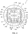
- FIG. 2 is a schematic view illustrating the vehicle lighting device 1 viewed from direction II in FIG. 1 .
- FIG. 2 is a schematic view of the vehicle lighting device 1 when viewed from a light emitting side.
- FIGS. 3A to 3D are schematic sectional views illustrating the vehicle lighting device 1 that is taken along line III-III in FIG. 2 .
- the vehicle lighting device 1 is provided with a socket 10, a light emitting module 20, and a power supplying portion 30.
- the socket 10 has a mounting portion 11, bayonets 12, a flange 13, and radiating fins 14.
- the mounting portion 11 is provided on a surface of the flange 13 on a side opposite to a side on which the radiating fins 14 are provided.
- An external shape of the mounting portion 11 can be columnar.
- the external shape of the mounting portion 11 is, for example, cylindrical.
- the mounting portion 11 has a recessed portion 11a that is opened to an end surface on a side opposite to a flange 13 side.
- a bottom surface 11a1 of the recessed portion 11a is provided with the light emitting module 20.
- the bayonets 12 are provided on an outside surface 11c (surface of the mounting portion 11 intersecting the end surface to which the recessed portion 11a is opened) of the mounting portion 11.
- the bayonets 12 protrude outward the vehicle lighting device 1.
- the bayonets 12 face the flange 13.
- the bayonets 12 are provided on a bottom surface 11a1 side (below a substrate 21) of the recessed portion 11a of the substrate 21.
- a plurality of bayonets 12 are provided.
- the bayonets 12 are used when the vehicle lighting device 1 is attached to a housing 101 of a vehicle lamp 100.
- the bayonets 12 are used for twist lock.
- the flange 13 has a plate shape.
- the flange 13 can have, for example, a disk shape.
- An outside surface 13a of the flange 13 is positioned on an outside of the vehicle lighting device 1 from an outside surface 12b of the bayonet 12.
- the radiating fins 14 are provided on a surface of the flange 13 on a side opposite to a side on which the mounting portion 11 is provided.
- a plurality of radiating fins 14 can be provided.
- the plurality of radiating fins 14 are provided so as to be parallel to each other.
- the radiating fin 14 can have a plate shape.
- the socket 10 is provided with a hole 10a into which an insulating portion 31 is inserted and a hole 10b into which a connector 105 is inserted.
- the connector 105 having a sealing member 105a is inserted into the hole 10b. Therefore, a cross section shape of the hole 10b is fitted to a cross section shape of the connector 105 having the sealing member 105a.
- heat generated in the light emitting module 20 is mainly transmitted to the radiating fins 14 via the mounting portion 11 and the flange 13. Heat transmitted to the radiating fins 14 is discharged from the radiating fins 14 to the outside.
- the socket 10 is formed of a material having high thermal conductivity considering that heat generated in the light emitting module 20 is transmitted to the outside.
- the material having high thermal conductivity can be, for example, metal, resin having high thermal conductivity, or the like. Resin having high thermal conductivity is obtained, for example, by mixing a filler made of aluminum oxide having high thermal conductivity to resin such as ployethylene terephthalate (PET) and nylon.
- PET ployethylene terephthalate
- the socket 10 is formed using resin having high thermal conductivity, it is possible to efficiently radiate heat generated in the light emitting module 20 and to achieve a light weight thereof.
- the light emitting module 20 has the substrate 21, a light emitting element 22, resistors 23, and a control element 24.
- the substrate 21 is provided in the bottom surface 11a1 of the recessed portion 11a.
- the substrate 21 has a plate shape.
- the planar shape of the substrate 21 can be, for example, a rectangle.
- a material or a structure of the substrate 21 is not particularly limited.
- the substrate 21 can be formed of an inorganic material such as ceramics (for example, aluminum oxide, aluminum nitride, and the like), an organic material such as paper phenol and glass epoxy, and the like.
- the substrate 21 may be obtained by coating a surface of a metal plate with an insulating material.
- the insulating material may be formed of an organic material or may be formed of an inorganic material.
- the substrate 21 is formed by using a material having high thermal conductivity in terms of heat radiation.
- a material having high thermal conductivity ceramics such as aluminum oxide or aluminum nitride, resin having high thermal conductivity, a material that is obtained by coating a surface of a metal plate with an insulating material, and the like can be exemplified.
- the substrate 21 may be a single layer or may be a multi-layer.
- a wiring pattern 21a is provided on the surface of the substrate 21.
- the wiring pattern 21a can be formed of a material containing silver as a main component.
- the wiring pattern 21a can be formed of, for example, silver or a silver alloy.
- a material of the wiring pattern 21a is not limited to a material containing silver as a main component.
- the wiring pattern 21a can be formed of, for example, a material containing copper as a main component.
- the light emitting element 22 is provided on a substrate 21 side opposite to a bottom surface 11a1 side of the recessed portion 11a.
- the light emitting element 22 is provided on the substrate 21.
- the light emitting element 22 is electrically connected to the wiring pattern 21a provided on the surface of the substrate 21.
- the light emitting element 22 can be, for example, a light emitting diode, an organic light emitting diode, a laser diode, and the like.
- a plurality of light emitting elements 22 can be provided.
- the plurality of light emitting elements 22 can be connected in series with each other.
- the light emitting elements 22 are connected in series with the resistors 23.
- a form of the light emitting element 22 is not particularly limited.
- the light emitting element 22 can be a light emitting element of a surface mounting type such as Plastic Leaded Chip Carrier (PLCC) type.
- PLCC Plastic Leaded Chip Carrier
- the light emitting element 22 can be, for example, a light emitting element having a lead wire of a shell type and the like.
- the light emitting element 22 can be mounted by Chip On Board (COB).
- COB Chip On Board
- the sealing portion can include a phosphor.
- the phosphor can be, for example, a YAG-based phosphor (yttrium-aluminum-garnet based fluorescent material).
- the light emitting element 22 is a blue light emitting diode and the phosphor is the YAG-based phosphor
- the YAG-based phosphor is excited by blue light emitted from the light emitting element 22 and yellow fluorescence is emitted from the YAG-based phosphor.
- white light is emitted from the vehicle lighting device 1 by mixing blue light and yellow light.
- types of the phosphors and types of the light emitting elements 22 are not limited to the examples described above. The types of the phosphors and the types of the light emitting elements 22 can be appropriately changed such that a desired emitting color is obtained in accordance with the application of the vehicle lighting device 1 and the like.
- the light emitting element 22 illustrated in FIGS. 1 and 2 is the light emitting element of the surface mounting type.
- the upper surface of the light emitting element 22 that is an emitting surface of light faces a front side of the vehicle lighting device 1 and mainly emits light on the front side of the vehicle lighting device 1.
- the number, sizes, and arrangements of the light emitting elements 22, and the like are not limited to the examples described above, and can be appropriately changed in accordance with the size and the application of the vehicle lighting device 1, and the like.
- the resistors 23 are provided on the substrate 21 side opposite to the bottom surface 11a1 side of the recessed portion 11a.
- the resistors 23 are provided on the substrate 21.
- the resistors 23 are electrically connected to the wiring pattern 21a disposed on the surface of the substrate 21.
- the resistors 23 can be, for example, resistors of a surface mounting type, resistors (metal oxide film resistor) having a lead wire, film-like resistors formed using a screen printing method, and the like.
- the resistors 23 illustrated in FIGS. 1 and 2 are the resistors of the surface mounting type.
- a material of the film-like resistor can be, for example, ruthenium oxide (RuO 2 ).
- the film-like resistor can be formed by using a screen printing method and a firing method. If the resistor 23 is the film-like resistor, it is possible to increase a contact area between the resistor 23 and the substrate 21. Therefore, it is possible to improve heat radiation property. In addition, a plurality of resistors 23 can be formed all at once. Therefore, it is possible to improve the productivity and it is possible to suppress variation in resistance values in the plurality of resistors 23.
- a value of a current flowing through the light emitting element 22 is made to fall within a predetermined range by the resistors 23 so that the brightness of the light emitting element 22 falls within a predetermined range.
- a value of the current flowing through the light emitting element 22 can be within a predetermined range by changing resistance values of the resistors 23.
- the resistors 23 are resistors of a surface mounting type, resistors having a lead wire, the resistors 23 having an appropriate resistance value according to the forward voltage characteristics of the light emitting element 22 are selected.
- the resistor 23 is the film-like resistor
- a part of the resistor 23 forms a removed portion 23a that is formed by removing a part of the resistor 23. Then, the resistance value of the resistor 23 is changed by a size of the removed portion 23a or the like. In this case, if the removed portion 23a is formed, the resistance value increases. For example, if the resistor 23 is irradiated with laser light, the removed portion 23a can be easily formed.
- the number, sizes, and arrangements of the resistors 23 and the removed portions 23a, and the like are not limited to the examples described above, and can be appropriately changed in accordance with the number and the application of the light emitting elements 22, and the like.
- the control element 24 is provided on a side of the substrate 21 opposite to the bottom surface 11a1 side of the recessed portion 11a.
- the control element 24 is provided on the substrate 21.
- the control element 24 is electrically connected to the wiring pattern 21a provided on the surface of the substrate 21.
- the control element 24 is provided so that a reverse voltage is not applied to the light emitting element 22 and pulse noise from a reverse direction is not applied to the light emitting element 22.
- the control element 24 can be, for example, a diode.
- the control element 24 can be, for example, a diode of a surface mounting type, a diode having a lead wire, or the like.
- the control element 24 illustrated in FIGS. 1 and 2 is the diode of the surface mounting type.
- a pull-down resistor 23b to detect disconnection of the light emitting element 22, to prevent erroneous lighting, and the like.
- a cover portion (not illustrated) for covering the wiring pattern, the film-like resistor, and the like.
- the cover portion can include, for example, a glass material.
- the power supplying portion 30 has an insulating portion 31 and power supply terminals 32.
- the insulating portion 31 is provided on an inside of the hole 10a.
- the insulating portion 31 can be pressed into the hole 10a, or can be mounted on the inside of the hole 10a.
- the insulating portion 31 can be integrally formed with the socket 10.
- the insulating portion 31 is formed of an insulating material.
- the insulating portion 31 is formed of a material having insulating properties and high thermal conductivity.
- the material having insulating properties and high thermal conductivity can be, for example, ceramics (for example, aluminum oxide, aluminum nitride, or the like), high thermal conductivity resin, or the like.
- a temperature of environment of use is -40°C to 85°C. Therefore, it is preferable that a thermal expansion coefficient of the material of the insulating portion 31 is as close as possible to the thermal expansion coefficient of the material of the socket 10. In this way, thermal stress generated between the insulating portion 31 and the socket 10 can be reduced.
- the material of the insulating portion 31 can be the high thermal conductivity resin contained in the socket 10, or can be resin contained in the high thermal conductivity resin.
- a plurality of power supply terminals 32 are provided.
- the plurality of power supply terminals 32 are provided on the inside of the insulating portion 31.
- the plurality of power supply terminals 32 extend inside the insulating portion 31.
- One end portion of each of the plurality of power supply terminals 32 is electrically connected to the light emitting module 20.
- the other end portion of each of the plurality of power supply terminals 32 protrudes from the insulating portion 31.
- the number and the shape of the power supply terminals 32, and the like are not limited to the examples and can be appropriately changed.
- the number and types of the light emitting elements 22, the resistors 23, and the control elements 24, and the like provided on the substrate 21 tend to increase.
- a frame-like member surrounding the light emitting element 22 and the wiring, a sealing portion provided on an inside of the frame-like member, and the like are further provided.
- an external dimension (sectional area dimension) of the mounting portion 11 increases, the area of the substrate can be increased.
- the mounting portion 11 is inserted into an attachment hole 101a of the housing 101 (see FIG. 4 ). Therefore, if the external dimension of the mounting portion 11 is increased, it is difficult to attach the vehicle lighting device 1 to the existing vehicle lamp 100. In addition, if the external dimension of the mounting portion 11 is increased, miniaturization of the vehicle lighting device 1 cannot be achieved.
- the substrate 21 protrudes outward from the outside surface 11c of the mounting portion 11, there is a concern that the mounting portion 11 cannot be inserted into the attachment hole 101a of the housing 101. Therefore, in general, the substrate 21 is provided on the inside from the outside surface 11c of the mounting portion 11. As a result, it is difficult to increase the area of the substrate.
- the vehicle lighting device 1 in a case where the vehicle lighting device 1 is viewed from a light emitting side (in a case where the vehicle lighting device 1 is viewed from the direction II in FIG. 1 ), at least one corner portion 21b of the substrate 21 overlaps with any one of the plurality of bayonets 12. Moreover, in a case of the vehicle lighting device 1 illustrated in FIG. 2 , all the corner portions 21b of the substrate 21 overlap with the bayonets 12.
- At least one corner portion 21b of the substrate 21 is provided on the outside of the outside surface 11c of the mounting portion 11.
- a portion of the substrate 21 provided on the outside of the outside surface 11c of the mounting portion 11 is provided on an inside from a periphery of the bayonet 12. That is, in a case where the vehicle lighting device 1 is viewed from the light emitting side, the substrate 21 does not protrude from the bayonets 12.
- the corner portions 21b of the substrate 21 are provided between the outside surface 12b of the bayonet 12 and the outside surface 11c of the mounting portion 11. Moreover, in a case of the vehicle lighting device 1 illustrated in FIG. 2 , the corner portion 21b of the substrate 21 is provided at a position of the outside surface 12b of the bayonet 12.
- a surface 21c of the substrate 21 on a side opposite to a side on which the light emitting element 22 is provided can be provided on an upper surface 12a of the bayonet 12.
- the surface 21c of the substrate 21 can be provided on the bottom surface 11a1 of the recessed portion opened to the upper surface 12a of the bayonet 12.
- a surface 21d of the substrate 21 on the side on which the light emitting element 22 is provided can be flush with the upper surface 12a of the bayonet 12.
- the surface 21d of the substrate 21 can also be located on a side opposite to the flange 13 side from the upper surface 12a of the bayonet 12. That is, the surface of the substrate 21 on the bottom surface 11a1 side of the recessed portion 11a can be provided above the upper surface 12a of the bayonet 12.
- the surface 21d of the substrate 21 can be provided on the flange 13 side from the upper surface 12a of the bayonet 12. That is, the surface of the substrate 21 on the bottom surface 11a1 side of the recessed portion 11a can be provided below the upper surface 12a of the bayonet 12.
- a metal substrate, thermal conductivity grease, a layer formed of adhesive (not illustrated), or the like can be interposed between the surface 21c on the substrate 21 side opposite to the side on which the light emitting element 22 is provided and the bottom surface 11a1 of the recessed portion 11a of the mounting portion 11.
- Thermal conductivity grease a layer formed of adhesive, or the like can be provided between the surface 21c of the substrate 21 on the side opposite to the side on which the light emitting element 22 is provided and the bayonet 12.
- a recessed portion into which the bayonet 12 is inserted is provided in the periphery of the attachment hole 101a of the housing 101 provided in the vehicle lamp 100. Therefore, even if the substrate 21 protrudes outward from the outside surface 11c of the mounting portion 11, the mounting portion 11 can be inserted into the attachment hole 101a of the housing 101 if it is above the bayonet 12.
- the mounting portion 11 is provided with a slit 11d.
- the slit 11d penetrates between a side surface 11a2 of the recessed portion 11a and the outside surface 11c of the mounting portion 11.
- the slit 11d extends between an end surface of the mounting portion 11 on the side opposite to the flange 13 side and an end surface of the bayonet 12 on the side opposite to the flange 13 side.
- the slit 11d is provided above the bayonet 12. That is, in a case where the vehicle lighting device 1 is viewed from the light emitting side, the slit 11d is provided at a position at which the bayonet 12 is provided in a circumferential direction of the mounting portion 11.
- the vicinity of at least one corner portion 21b of the substrate 21 is provided on an inside of the slit 11d.
- the substrate 21 and a wall surface of the slit 11d may be in contact with each other, or may have a gap.
- FIG. 4 is a schematic view illustrating a vehicle lighting device 1a according to another embodiment.
- FIG. 4 is a schematic view in a case where the vehicle lighting device 1a is viewed from a light emitting side.
- FIG. 4 in order to avoid complication, only a mounting portion 11, a bayonet 12, a flange 13, and a substrate 21 are drawn.
- all the corner portions 21b of the substrate 21 are provided on the outside of the outside surface 11c of the mounting portion 11.
- a part of corner portions 21b of the substrate 21 is provided on an outside of an outside surface 11c of the mounting portion 11.
- At least one corner portion 21b of the substrate 21 may be provided on the outside of the outside surface 11c of the mounting portion 11. If at least one corner portion 21b of the substrate 21 is provided on the outside of the outside surface 11c of the mounting portion 11, it is possible to increase an area of the substrate. However, if the number of the corner portions 21b of the substrate 21 provided on the outside of the outside surface 11c of the mounting portion 11 is increased, it is possible to further increase the area of the substrate.
- the plurality of bayonets 12 are provided at the positions point symmetrical with respect to the center of the mounting portion 11.
- a plurality of bayonets 12 are provided at arbitrary positions.
- the positions of the bayonets 12 may not match the positions of the corner portions 21b of the substrate 21. However, if even one of the positions of the bayonets 12 matches one of the positions of the corner portions 21b of the substrate 21, it is possible to increase the area of the substrate. However, if the number of the positions of the bayonets 12 matching the positions of the corner portions 21b of the substrate 21 is increased, it is possible to increase the area of the substrate.
- the corner portion 21b of the substrate 21 is provided on the inside from the outside surface 11c of the mounting portion 11.
- the planar shape of the substrate 21 is a square.
- a planar shape of the substrate 21 is a rectangle.
- the planar shape of the substrate 21 can also be an arbitrary shape.
- the planar shape of the substrate 21 is quadrangular, the number of the substrates 21, which can be manufactured from a planar material having a predetermined external dimension, can be increased.
- FIGS. 2 and 4 a case where four bayonets 12 are provided is illustrated, but the number of the bayonets 12 may be two or more. In this case, if the number of the bayonets 12 is three or more, postures of the vehicle lighting devices 1 and 1a are stabilized. Moreover, it is preferable that the number of the bayonets 12 is equal to the number of the corner portions 21b of the substrate 21 or is greater than that thereof.
- the vehicle lighting devices 1 and 1a it is possible to increase the area of the substrate. If the size of the substrate 21 can be increased, the number and the types of elements, members, and the like provided in the substrate 21 are easily increased. Therefore, the advanced function and the multi-function of the vehicle lighting device 1 can be performed.
- the number of the light emitting elements 22, the resistors 23, and the control elements 24 provided in the substrate 21, and the like is increased, a heating value is also increased.
- the size of the substrate 21 can be increased, it is possible to improve the radiation properties.
- the bayonets 12 are in contact with the vehicle lamp 100. Therefore, heat generated in the light emitting module 20 can escape to the vehicle lamp 100 via the vicinity of the corner portions 21b of the substrate 21 and the bayonets 12.
- the slit 11d is provided, external air is easily introduced into the inside of the recessed portion 11a. Therefore, it is possible to further effectively suppress the increase in the temperature of the light emitting element 22.
- the vehicle lighting device 1 since it is unnecessary to change the external dimension of the mounting portion 11, it is possible to mount the vehicle lighting device 1 on the existing vehicle lamp 100. In addition, the miniaturization of the vehicle lighting device 1 can be achieved.
- the vehicle lamp 100 is a front combination light provided in the automobile.
- the vehicle lamp 100 is not limited to the front combination light provided in the automobile.
- the vehicle lamp 100 may be a vehicle lamp provided in an automobile, a railway vehicle, and the like.
- FIG. 5 is a partial sectional view schematically illustrating the vehicle lamp 100.
- the vehicle lighting device 1 As illustrated in FIG. 5 , the vehicle lighting device 1, the housing 101, a cover 102, an optical element portion 103, a sealing member 104, and the connector 105 are provided in the vehicle lamp 100.
- the housing 101 holds the mounting portion 11.
- the housing 101 has a box shape of which one end portion is opened.
- the housing 101 can be formed of, for example, resin and the like through which light is not transmitted.
- the attachment hole 101a into which a portion of the mounting portion 11 in which the bayonets 12 are provided is inserted is provided in a bottom surface of the housing 101. Recessed portions into which the bayonets 12 provided in the mounting portion 11 are inserted are provided in a periphery of the attachment hole 101a.
- an attaching member having the attachment hole 101a may be provided in the housing 101.
- the cover 102 is provided so as to close an opening of the housing 101.
- the cover 102 can be formed of resin and the like having a light-transmitting property.
- the cover 102 can have functions of a lens and the like.
- the optical element portion 103 performs reflection, diffusion, guiding, and condensing of the light emitted from the vehicle lighting device 1, formation of a predetermined light distribution pattern, and the like.
- the optical element portion 103 illustrated in FIG. 5 is a reflector.
- the optical element portion 103 reflects the light emitted from the vehicle lighting device 1, and causes the predetermined light distribution pattern to be formed.
- the sealing member 104 is provided between the flange 13 and the housing 101.
- the sealing member 104 can have an annular shape.
- the sealing member 104 can be formed of a material having elasticity such as rubber or silicone resin.
- the sealing member 104 When attaching the vehicle lighting device 1 to the vehicle lamp 100, the sealing member 104 is interposed between the flange 13 and the housing 101. Thus, an inside space of the housing 101 is closed by the sealing member 104. In addition, the bayonets 12 are pressed against the housing 101 by an elastic force of the sealing member 104. Thus, the vehicle lighting device 1 can be prevented from being separated from the housing 101.
- the connectors 105 are fitted into end portions of the plurality of power supply terminals 32 exposed on the inside of the hole 10b. Power supply (not illustrated) and the like are electrically connected to the connectors 105. Therefore, power supply (not illustrated) and the like are electrically connected to the light emitting elements 22 by fitting the connectors 105 into the end portions of the power supply terminals 32.
- the connectors 105 have stepped portions. Then, the sealing member 105a is attached to the stepped portions (see FIG. 1 ). The sealing member 105a is provided to prevent entrance of water on the inside of the hole 10b. When the connector 105 having the sealing member 105a is inserted into the hole 10b, the hole 10b is sealed to be water tightness.
- the sealing member 105a can have an annular shape.
- the sealing member 105a can be formed of a material having elasticity such as rubber or silicone resin.
- the connector 105 can also be joined, for example, to an element on the socket 10 side using adhesive or the like.
Landscapes
- Engineering & Computer Science (AREA)
- General Engineering & Computer Science (AREA)
- Physics & Mathematics (AREA)
- Microelectronics & Electronic Packaging (AREA)
- Optics & Photonics (AREA)
- Non-Portable Lighting Devices Or Systems Thereof (AREA)
- Fastening Of Light Sources Or Lamp Holders (AREA)
- Lighting Device Outwards From Vehicle And Optical Signal (AREA)
Claims (4)
- Fahrzeugbeleuchtungsvorrichtung (1), umfassend:einen Befestigungsabschnitt (11), der einen vertieften Abschnitt (11a) aufweist;mehrere Bajonette (12), die auf einer Außenfläche (11c) des Befestigungsabschnitts (11) vorgesehen sind;ein Substrat (21), das auf einer Bodenfläche (11a1) des vertieften Abschnitts (11a) vorgesehen ist; undein lichtemittierendes Element (22), das auf einer Seite des Substrats (21) gegenüber einer Seite der Bodenfläche (11a1) des vertieften Abschnitts (11a) vorgesehen ist;dadurch gekennzeichnet, dassin einem Fall, in dem die Fahrzeugbeleuchtungsvorrichtung (1) von einer lichtemittierenden Seite betrachtet wird, mindestens ein Eckabschnitt (21b) des Substrats (21) mit einem beliebigen der mehreren Bajonette (12) überlappt.
- Vorrichtung (1) nach Anspruch 1,
wobei der Befestigungsabschnitt (11) mindestens einen Schlitz (11d) aufweist, der zwischen einer Seitenfläche des vertieften Abschnitts (11a) und der Außenfläche (11c) des Befestigungsabschnitts (11) eindringt,
und
eine Nähe mindestens eines Eckabschnitts (21b) des Substrats (21) auf einer Innenseite des Schlitzes (11d) vorgesehen ist. - Vorrichtung (1) nach einem der Ansprüche 1 bis 2, wobei eine ebene Form des Substrats (21) ein Rechteck ist.
- Fahrzeuglampe (100), umfassend:die Fahrzeugbeleuchtungsvorrichtung (1) nach einem der Ansprüche 1 bis 3; undein Gehäuse (101), an dem die Fahrzeugbeleuchtungsvorrichtung (1) angebracht ist.
Applications Claiming Priority (1)
| Application Number | Priority Date | Filing Date | Title |
|---|---|---|---|
| JP2016106340A JP6738532B2 (ja) | 2016-05-27 | 2016-05-27 | 車両用照明装置、および車両用灯具 |
Publications (2)
| Publication Number | Publication Date |
|---|---|
| EP3249290A1 EP3249290A1 (de) | 2017-11-29 |
| EP3249290B1 true EP3249290B1 (de) | 2018-10-31 |
Family
ID=57984823
Family Applications (1)
| Application Number | Title | Priority Date | Filing Date |
|---|---|---|---|
| EP17154813.4A Active EP3249290B1 (de) | 2016-05-27 | 2017-02-06 | Fahrzeugbeleuchtungsvorrichtung und fahrzeuglampe |
Country Status (4)
| Country | Link |
|---|---|
| US (1) | US10371340B2 (de) |
| EP (1) | EP3249290B1 (de) |
| JP (1) | JP6738532B2 (de) |
| CN (1) | CN206708912U (de) |
Families Citing this family (6)
| Publication number | Priority date | Publication date | Assignee | Title |
|---|---|---|---|---|
| FR3055943B1 (fr) * | 2016-09-15 | 2020-10-02 | Valeo Vision | Cablage d'une source lumineuse de haute resolution |
| FR3074881A1 (fr) | 2017-12-07 | 2019-06-14 | Valeo Vision | Module lumineux pour vehicule automobile |
| JP7069522B2 (ja) * | 2018-03-08 | 2022-05-18 | 東芝ライテック株式会社 | 車両用照明装置および車両用灯具 |
| JP6879270B2 (ja) | 2018-07-20 | 2021-06-02 | 日亜化学工業株式会社 | 発光装置 |
| JP7196577B2 (ja) * | 2018-12-05 | 2022-12-27 | 東芝ライテック株式会社 | 車両用照明装置、および車両用灯具 |
| JP7445212B2 (ja) * | 2019-11-22 | 2024-03-07 | 東芝ライテック株式会社 | 車両用照明装置、および車両用灯具 |
Family Cites Families (26)
| Publication number | Priority date | Publication date | Assignee | Title |
|---|---|---|---|---|
| US5378158A (en) * | 1994-01-21 | 1995-01-03 | Delco Electronics Corporation | Light emitting diode and socket assembly |
| DE10200831A1 (de) * | 2002-01-02 | 2003-07-17 | Philips Intellectual Property | Lampe und Scheinwerfer zur einfachen Montage |
| DE102004062990A1 (de) * | 2004-12-22 | 2006-07-06 | Patent-Treuhand-Gesellschaft für elektrische Glühlampen mbH | Beleuchtungseinrichtung mit mindestens einer Leuchtdiode und Fahrzeugscheinwerfer |
| US20080080187A1 (en) * | 2006-09-28 | 2008-04-03 | Purinton Richard S | Sealed LED light bulb |
| CA2682631C (en) * | 2007-04-03 | 2015-09-08 | Osram Gesellschaft Mit Beschraenkter Haftung | Semiconductor light module |
| US8591070B2 (en) * | 2009-03-05 | 2013-11-26 | Osram Gmbh | Lighting device having a socket and bulb fitting |
| DE102009040572A1 (de) * | 2009-09-08 | 2011-03-10 | Osram Gesellschaft mit beschränkter Haftung | Lampeneinheit |
| FR2950673B1 (fr) * | 2009-09-30 | 2011-12-09 | Valeo Vision | Support pour source lumineuse de module d'eclairage |
| JP5779329B2 (ja) | 2010-01-19 | 2015-09-16 | 市光工業株式会社 | 車両用灯具 |
| JP5488310B2 (ja) * | 2010-07-30 | 2014-05-14 | 市光工業株式会社 | 車両用灯具の半導体型光源の光源ユニット、車両用灯具 |
| JP2012043750A (ja) * | 2010-08-23 | 2012-03-01 | Ichikoh Ind Ltd | 車両用灯具の半導体型光源の光源ユニット、車両用灯具 |
| US8602597B2 (en) * | 2010-11-16 | 2013-12-10 | Cree, Inc. | Heat sink retaining structure for light emitting device board assemblies, and methods |
| TWM409368U (en) * | 2011-01-28 | 2011-08-11 | Fin Core Corp | LED lamps |
| WO2012162927A1 (zh) * | 2011-06-02 | 2012-12-06 | 天津方合科技发展有限公司 | 近光带有明暗截止线的汽车前照灯led光学组件 |
| US8764248B1 (en) * | 2012-03-02 | 2014-07-01 | Jerome H. Simon | LED lighting systems comprising modules and components that perform multiple operational functions |
| US9557026B2 (en) * | 2012-05-29 | 2017-01-31 | Ichikoh Industries, Ltd. | Vehicular lighting instrument semiconductor light source light source unit and vehicular lighting instrument |
| JP6003382B2 (ja) * | 2012-08-13 | 2016-10-05 | 市光工業株式会社 | 車両用灯具の半導体型光源、車両用灯具の半導体型光源ユニット、車両用灯具 |
| JP2014203575A (ja) * | 2013-04-02 | 2014-10-27 | 東芝ライテック株式会社 | 照明装置 |
| WO2014173850A1 (en) * | 2013-04-25 | 2014-10-30 | Koninklijke Philips N.V. | A light emitting diode module |
| JP6211326B2 (ja) * | 2013-07-22 | 2017-10-11 | 株式会社小糸製作所 | 光源装置および車両用灯具 |
| JP2015079604A (ja) * | 2013-10-16 | 2015-04-23 | 株式会社小糸製作所 | 光源装置および車両用灯具 |
| TWM474106U (zh) * | 2013-12-03 | 2014-03-11 | yu-xuan Chen | 發光二極體燈具 |
| JP6467206B2 (ja) * | 2014-01-28 | 2019-02-06 | 株式会社小糸製作所 | 光源ユニット |
| DE202014001946U1 (de) * | 2014-02-28 | 2014-03-17 | Osram Gmbh | Lampe |
| DE102015201153A1 (de) * | 2015-01-23 | 2016-07-28 | Osram Gmbh | Beleuchtungseinrichtung |
| JP6621274B2 (ja) * | 2015-09-08 | 2019-12-18 | 株式会社小糸製作所 | 光源モジュール |
-
2016
- 2016-05-27 JP JP2016106340A patent/JP6738532B2/ja active Active
-
2017
- 2017-02-06 EP EP17154813.4A patent/EP3249290B1/de active Active
- 2017-02-09 US US15/428,574 patent/US10371340B2/en active Active
- 2017-02-22 CN CN201720160989.1U patent/CN206708912U/zh active Active
Non-Patent Citations (1)
| Title |
|---|
| None * |
Also Published As
| Publication number | Publication date |
|---|---|
| US20170343180A1 (en) | 2017-11-30 |
| JP2017212166A (ja) | 2017-11-30 |
| CN206708912U (zh) | 2017-12-05 |
| US10371340B2 (en) | 2019-08-06 |
| JP6738532B2 (ja) | 2020-08-12 |
| EP3249290A1 (de) | 2017-11-29 |
Similar Documents
| Publication | Publication Date | Title |
|---|---|---|
| EP3249290B1 (de) | Fahrzeugbeleuchtungsvorrichtung und fahrzeuglampe | |
| US10465898B2 (en) | Vehicle lighting device and vehicle lamp | |
| JP2019149282A (ja) | 車両用照明装置、車両用灯具、および車両用照明装置の製造方法 | |
| US10903192B2 (en) | Vehicle luminaire and vehicle lamp | |
| JP2019036404A (ja) | 車両用照明装置および車両用灯具 | |
| EP3584497B1 (de) | Fahrzeugleuchte und fahrzeuglampenvorrichtung | |
| US9958130B2 (en) | Vehicle lighting device, vehicle lamp, and method of manufacturing vehicle lighting device | |
| EP3537033B1 (de) | Fahrzeugleuchte, fahrzeuglampe und verfahren zur herstellung einer fahrzeugleuchte | |
| JP7157915B2 (ja) | 車両用照明装置および車両用灯具 | |
| US20170223805A1 (en) | Vehicle lighting device and vehicle lamp | |
| JP2018098048A (ja) | 車両用照明装置および車両用灯具 | |
| US20200355342A1 (en) | Vehicle Luminaire and Vehicle Lamp | |
| JP2017168212A (ja) | 車両用照明装置および車両用灯具 | |
| JP6536327B2 (ja) | 車両用灯具 | |
| JP6656578B2 (ja) | 車両用照明装置、及び車両用灯具 | |
| CN210107280U (zh) | 车辆用照明装置以及车辆用灯具 | |
| JP2018085300A (ja) | 車両用照明装置および車両用灯具 | |
| JP2017224466A (ja) | 車両用照明装置、および車両用灯具 | |
| JP2020017350A (ja) | 車両用照明装置、および車両用灯具 | |
| EP3892914B1 (de) | Fahrzeugleuchte | |
| CN220523929U (zh) | 车辆用照明装置以及车辆用灯具 | |
| JP2018085301A (ja) | 車両用照明装置および車両用灯具 | |
| JP2020017427A (ja) | 車両用照明装置、および車両用灯具 | |
| JP2024031398A (ja) | 車両用照明装置、および車両用灯具 | |
| JP2023175148A (ja) | 車両用照明装置、および車両用灯具 |
Legal Events
| Date | Code | Title | Description |
|---|---|---|---|
| PUAI | Public reference made under article 153(3) epc to a published international application that has entered the european phase |
Free format text: ORIGINAL CODE: 0009012 |
|
| STAA | Information on the status of an ep patent application or granted ep patent |
Free format text: STATUS: THE APPLICATION HAS BEEN PUBLISHED |
|
| AK | Designated contracting states |
Kind code of ref document: A1 Designated state(s): AL AT BE BG CH CY CZ DE DK EE ES FI FR GB GR HR HU IE IS IT LI LT LU LV MC MK MT NL NO PL PT RO RS SE SI SK SM TR |
|
| AX | Request for extension of the european patent |
Extension state: BA ME |
|
| STAA | Information on the status of an ep patent application or granted ep patent |
Free format text: STATUS: REQUEST FOR EXAMINATION WAS MADE |
|
| REG | Reference to a national code |
Ref country code: DE Ref legal event code: R079 Ref document number: 602017000727 Country of ref document: DE Free format text: PREVIOUS MAIN CLASS: F21V0023000000 Ipc: F21S0041190000 |
|
| 17P | Request for examination filed |
Effective date: 20180124 |
|
| RBV | Designated contracting states (corrected) |
Designated state(s): AL AT BE BG CH CY CZ DE DK EE ES FI FR GB GR HR HU IE IS IT LI LT LU LV MC MK MT NL NO PL PT RO RS SE SI SK SM TR |
|
| RIC1 | Information provided on ipc code assigned before grant |
Ipc: F21Y 115/10 20160101ALN20180220BHEP Ipc: F21S 41/19 20180101AFI20180220BHEP Ipc: F21V 23/00 20150101ALI20180220BHEP Ipc: F21V 19/00 20060101ALI20180220BHEP |
|
| GRAP | Despatch of communication of intention to grant a patent |
Free format text: ORIGINAL CODE: EPIDOSNIGR1 |
|
| STAA | Information on the status of an ep patent application or granted ep patent |
Free format text: STATUS: GRANT OF PATENT IS INTENDED |
|
| INTG | Intention to grant announced |
Effective date: 20180514 |
|
| GRAS | Grant fee paid |
Free format text: ORIGINAL CODE: EPIDOSNIGR3 |
|
| GRAA | (expected) grant |
Free format text: ORIGINAL CODE: 0009210 |
|
| STAA | Information on the status of an ep patent application or granted ep patent |
Free format text: STATUS: THE PATENT HAS BEEN GRANTED |
|
| AK | Designated contracting states |
Kind code of ref document: B1 Designated state(s): AL AT BE BG CH CY CZ DE DK EE ES FI FR GB GR HR HU IE IS IT LI LT LU LV MC MK MT NL NO PL PT RO RS SE SI SK SM TR |
|
| REG | Reference to a national code |
Ref country code: CH Ref legal event code: EP Ref country code: GB Ref legal event code: FG4D |
|
| REG | Reference to a national code |
Ref country code: AT Ref legal event code: REF Ref document number: 1059829 Country of ref document: AT Kind code of ref document: T Effective date: 20181115 |
|
| REG | Reference to a national code |
Ref country code: DE Ref legal event code: R096 Ref document number: 602017000727 Country of ref document: DE |
|
| REG | Reference to a national code |
Ref country code: IE Ref legal event code: FG4D |
|
| REG | Reference to a national code |
Ref country code: NL Ref legal event code: MP Effective date: 20181031 |
|
| REG | Reference to a national code |
Ref country code: LT Ref legal event code: MG4D |
|
| REG | Reference to a national code |
Ref country code: AT Ref legal event code: MK05 Ref document number: 1059829 Country of ref document: AT Kind code of ref document: T Effective date: 20181031 |
|
| PG25 | Lapsed in a contracting state [announced via postgrant information from national office to epo] |
Ref country code: FI Free format text: LAPSE BECAUSE OF FAILURE TO SUBMIT A TRANSLATION OF THE DESCRIPTION OR TO PAY THE FEE WITHIN THE PRESCRIBED TIME-LIMIT Effective date: 20181031 Ref country code: LV Free format text: LAPSE BECAUSE OF FAILURE TO SUBMIT A TRANSLATION OF THE DESCRIPTION OR TO PAY THE FEE WITHIN THE PRESCRIBED TIME-LIMIT Effective date: 20181031 Ref country code: HR Free format text: LAPSE BECAUSE OF FAILURE TO SUBMIT A TRANSLATION OF THE DESCRIPTION OR TO PAY THE FEE WITHIN THE PRESCRIBED TIME-LIMIT Effective date: 20181031 Ref country code: IS Free format text: LAPSE BECAUSE OF FAILURE TO SUBMIT A TRANSLATION OF THE DESCRIPTION OR TO PAY THE FEE WITHIN THE PRESCRIBED TIME-LIMIT Effective date: 20190228 Ref country code: PL Free format text: LAPSE BECAUSE OF FAILURE TO SUBMIT A TRANSLATION OF THE DESCRIPTION OR TO PAY THE FEE WITHIN THE PRESCRIBED TIME-LIMIT Effective date: 20181031 Ref country code: AT Free format text: LAPSE BECAUSE OF FAILURE TO SUBMIT A TRANSLATION OF THE DESCRIPTION OR TO PAY THE FEE WITHIN THE PRESCRIBED TIME-LIMIT Effective date: 20181031 Ref country code: BG Free format text: LAPSE BECAUSE OF FAILURE TO SUBMIT A TRANSLATION OF THE DESCRIPTION OR TO PAY THE FEE WITHIN THE PRESCRIBED TIME-LIMIT Effective date: 20190131 Ref country code: LT Free format text: LAPSE BECAUSE OF FAILURE TO SUBMIT A TRANSLATION OF THE DESCRIPTION OR TO PAY THE FEE WITHIN THE PRESCRIBED TIME-LIMIT Effective date: 20181031 Ref country code: NO Free format text: LAPSE BECAUSE OF FAILURE TO SUBMIT A TRANSLATION OF THE DESCRIPTION OR TO PAY THE FEE WITHIN THE PRESCRIBED TIME-LIMIT Effective date: 20190131 Ref country code: ES Free format text: LAPSE BECAUSE OF FAILURE TO SUBMIT A TRANSLATION OF THE DESCRIPTION OR TO PAY THE FEE WITHIN THE PRESCRIBED TIME-LIMIT Effective date: 20181031 |
|
| PG25 | Lapsed in a contracting state [announced via postgrant information from national office to epo] |
Ref country code: NL Free format text: LAPSE BECAUSE OF FAILURE TO SUBMIT A TRANSLATION OF THE DESCRIPTION OR TO PAY THE FEE WITHIN THE PRESCRIBED TIME-LIMIT Effective date: 20181031 Ref country code: PT Free format text: LAPSE BECAUSE OF FAILURE TO SUBMIT A TRANSLATION OF THE DESCRIPTION OR TO PAY THE FEE WITHIN THE PRESCRIBED TIME-LIMIT Effective date: 20190301 Ref country code: RS Free format text: LAPSE BECAUSE OF FAILURE TO SUBMIT A TRANSLATION OF THE DESCRIPTION OR TO PAY THE FEE WITHIN THE PRESCRIBED TIME-LIMIT Effective date: 20181031 Ref country code: SE Free format text: LAPSE BECAUSE OF FAILURE TO SUBMIT A TRANSLATION OF THE DESCRIPTION OR TO PAY THE FEE WITHIN THE PRESCRIBED TIME-LIMIT Effective date: 20181031 Ref country code: AL Free format text: LAPSE BECAUSE OF FAILURE TO SUBMIT A TRANSLATION OF THE DESCRIPTION OR TO PAY THE FEE WITHIN THE PRESCRIBED TIME-LIMIT Effective date: 20181031 Ref country code: GR Free format text: LAPSE BECAUSE OF FAILURE TO SUBMIT A TRANSLATION OF THE DESCRIPTION OR TO PAY THE FEE WITHIN THE PRESCRIBED TIME-LIMIT Effective date: 20190201 |
|
| PG25 | Lapsed in a contracting state [announced via postgrant information from national office to epo] |
Ref country code: IT Free format text: LAPSE BECAUSE OF FAILURE TO SUBMIT A TRANSLATION OF THE DESCRIPTION OR TO PAY THE FEE WITHIN THE PRESCRIBED TIME-LIMIT Effective date: 20181031 Ref country code: CZ Free format text: LAPSE BECAUSE OF FAILURE TO SUBMIT A TRANSLATION OF THE DESCRIPTION OR TO PAY THE FEE WITHIN THE PRESCRIBED TIME-LIMIT Effective date: 20181031 Ref country code: DK Free format text: LAPSE BECAUSE OF FAILURE TO SUBMIT A TRANSLATION OF THE DESCRIPTION OR TO PAY THE FEE WITHIN THE PRESCRIBED TIME-LIMIT Effective date: 20181031 |
|
| REG | Reference to a national code |
Ref country code: DE Ref legal event code: R097 Ref document number: 602017000727 Country of ref document: DE |
|
| PG25 | Lapsed in a contracting state [announced via postgrant information from national office to epo] |
Ref country code: SM Free format text: LAPSE BECAUSE OF FAILURE TO SUBMIT A TRANSLATION OF THE DESCRIPTION OR TO PAY THE FEE WITHIN THE PRESCRIBED TIME-LIMIT Effective date: 20181031 Ref country code: EE Free format text: LAPSE BECAUSE OF FAILURE TO SUBMIT A TRANSLATION OF THE DESCRIPTION OR TO PAY THE FEE WITHIN THE PRESCRIBED TIME-LIMIT Effective date: 20181031 Ref country code: SK Free format text: LAPSE BECAUSE OF FAILURE TO SUBMIT A TRANSLATION OF THE DESCRIPTION OR TO PAY THE FEE WITHIN THE PRESCRIBED TIME-LIMIT Effective date: 20181031 Ref country code: RO Free format text: LAPSE BECAUSE OF FAILURE TO SUBMIT A TRANSLATION OF THE DESCRIPTION OR TO PAY THE FEE WITHIN THE PRESCRIBED TIME-LIMIT Effective date: 20181031 |
|
| PLBE | No opposition filed within time limit |
Free format text: ORIGINAL CODE: 0009261 |
|
| STAA | Information on the status of an ep patent application or granted ep patent |
Free format text: STATUS: NO OPPOSITION FILED WITHIN TIME LIMIT |
|
| 26N | No opposition filed |
Effective date: 20190801 |
|
| PG25 | Lapsed in a contracting state [announced via postgrant information from national office to epo] |
Ref country code: MC Free format text: LAPSE BECAUSE OF FAILURE TO SUBMIT A TRANSLATION OF THE DESCRIPTION OR TO PAY THE FEE WITHIN THE PRESCRIBED TIME-LIMIT Effective date: 20181031 Ref country code: SI Free format text: LAPSE BECAUSE OF FAILURE TO SUBMIT A TRANSLATION OF THE DESCRIPTION OR TO PAY THE FEE WITHIN THE PRESCRIBED TIME-LIMIT Effective date: 20181031 Ref country code: LU Free format text: LAPSE BECAUSE OF NON-PAYMENT OF DUE FEES Effective date: 20190206 |
|
| REG | Reference to a national code |
Ref country code: BE Ref legal event code: MM Effective date: 20190228 |
|
| REG | Reference to a national code |
Ref country code: IE Ref legal event code: MM4A |
|
| PG25 | Lapsed in a contracting state [announced via postgrant information from national office to epo] |
Ref country code: IE Free format text: LAPSE BECAUSE OF NON-PAYMENT OF DUE FEES Effective date: 20190206 |
|
| PG25 | Lapsed in a contracting state [announced via postgrant information from national office to epo] |
Ref country code: BE Free format text: LAPSE BECAUSE OF NON-PAYMENT OF DUE FEES Effective date: 20190228 |
|
| PG25 | Lapsed in a contracting state [announced via postgrant information from national office to epo] |
Ref country code: TR Free format text: LAPSE BECAUSE OF FAILURE TO SUBMIT A TRANSLATION OF THE DESCRIPTION OR TO PAY THE FEE WITHIN THE PRESCRIBED TIME-LIMIT Effective date: 20181031 |
|
| PG25 | Lapsed in a contracting state [announced via postgrant information from national office to epo] |
Ref country code: MT Free format text: LAPSE BECAUSE OF NON-PAYMENT OF DUE FEES Effective date: 20190206 |
|
| REG | Reference to a national code |
Ref country code: CH Ref legal event code: PL |
|
| PG25 | Lapsed in a contracting state [announced via postgrant information from national office to epo] |
Ref country code: CH Free format text: LAPSE BECAUSE OF NON-PAYMENT OF DUE FEES Effective date: 20200229 Ref country code: LI Free format text: LAPSE BECAUSE OF NON-PAYMENT OF DUE FEES Effective date: 20200229 |
|
| PG25 | Lapsed in a contracting state [announced via postgrant information from national office to epo] |
Ref country code: CY Free format text: LAPSE BECAUSE OF FAILURE TO SUBMIT A TRANSLATION OF THE DESCRIPTION OR TO PAY THE FEE WITHIN THE PRESCRIBED TIME-LIMIT Effective date: 20181031 |
|
| PG25 | Lapsed in a contracting state [announced via postgrant information from national office to epo] |
Ref country code: HU Free format text: LAPSE BECAUSE OF FAILURE TO SUBMIT A TRANSLATION OF THE DESCRIPTION OR TO PAY THE FEE WITHIN THE PRESCRIBED TIME-LIMIT; INVALID AB INITIO Effective date: 20170206 |
|
| GBPC | Gb: european patent ceased through non-payment of renewal fee |
Effective date: 20210206 |
|
| PG25 | Lapsed in a contracting state [announced via postgrant information from national office to epo] |
Ref country code: GB Free format text: LAPSE BECAUSE OF NON-PAYMENT OF DUE FEES Effective date: 20210206 |
|
| PG25 | Lapsed in a contracting state [announced via postgrant information from national office to epo] |
Ref country code: MK Free format text: LAPSE BECAUSE OF FAILURE TO SUBMIT A TRANSLATION OF THE DESCRIPTION OR TO PAY THE FEE WITHIN THE PRESCRIBED TIME-LIMIT Effective date: 20181031 |
|
| PGFP | Annual fee paid to national office [announced via postgrant information from national office to epo] |
Ref country code: FR Payment date: 20231206 Year of fee payment: 8 |
|
| PGFP | Annual fee paid to national office [announced via postgrant information from national office to epo] |
Ref country code: DE Payment date: 20231205 Year of fee payment: 8 |