EP3249281A1 - Distribution de gaz comprimé - Google Patents
Distribution de gaz comprimé Download PDFInfo
- Publication number
- EP3249281A1 EP3249281A1 EP16170898.7A EP16170898A EP3249281A1 EP 3249281 A1 EP3249281 A1 EP 3249281A1 EP 16170898 A EP16170898 A EP 16170898A EP 3249281 A1 EP3249281 A1 EP 3249281A1
- Authority
- EP
- European Patent Office
- Prior art keywords
- gas
- storage
- vessel
- storage vessels
- vessels
- Prior art date
- Legal status (The legal status is an assumption and is not a legal conclusion. Google has not performed a legal analysis and makes no representation as to the accuracy of the status listed.)
- Granted
Links
- 238000000034 method Methods 0.000 claims abstract description 93
- 239000007789 gas Substances 0.000 abstract description 561
- 239000001257 hydrogen Substances 0.000 abstract description 17
- 229910052739 hydrogen Inorganic materials 0.000 abstract description 17
- UFHFLCQGNIYNRP-UHFFFAOYSA-N Hydrogen Chemical compound [H][H] UFHFLCQGNIYNRP-UHFFFAOYSA-N 0.000 abstract description 15
- 230000006835 compression Effects 0.000 description 8
- 238000007906 compression Methods 0.000 description 8
- 230000003247 decreasing effect Effects 0.000 description 8
- 238000010586 diagram Methods 0.000 description 3
- 239000002828 fuel tank Substances 0.000 description 3
- 230000014509 gene expression Effects 0.000 description 3
- 230000007423 decrease Effects 0.000 description 2
- 150000002431 hydrogen Chemical class 0.000 description 2
- VNWKTOKETHGBQD-UHFFFAOYSA-N methane Chemical compound C VNWKTOKETHGBQD-UHFFFAOYSA-N 0.000 description 2
- 239000004215 Carbon black (E152) Substances 0.000 description 1
- 239000012530 fluid Substances 0.000 description 1
- 239000000446 fuel Substances 0.000 description 1
- 239000007788 liquid Substances 0.000 description 1
- 239000003345 natural gas Substances 0.000 description 1
Images


Classifications
-
- F—MECHANICAL ENGINEERING; LIGHTING; HEATING; WEAPONS; BLASTING
- F17—STORING OR DISTRIBUTING GASES OR LIQUIDS
- F17C—VESSELS FOR CONTAINING OR STORING COMPRESSED, LIQUEFIED OR SOLIDIFIED GASES; FIXED-CAPACITY GAS-HOLDERS; FILLING VESSELS WITH, OR DISCHARGING FROM VESSELS, COMPRESSED, LIQUEFIED, OR SOLIDIFIED GASES
- F17C5/00—Methods or apparatus for filling containers with liquefied, solidified, or compressed gases under pressures
- F17C5/06—Methods or apparatus for filling containers with liquefied, solidified, or compressed gases under pressures for filling with compressed gases
-
- F—MECHANICAL ENGINEERING; LIGHTING; HEATING; WEAPONS; BLASTING
- F17—STORING OR DISTRIBUTING GASES OR LIQUIDS
- F17C—VESSELS FOR CONTAINING OR STORING COMPRESSED, LIQUEFIED OR SOLIDIFIED GASES; FIXED-CAPACITY GAS-HOLDERS; FILLING VESSELS WITH, OR DISCHARGING FROM VESSELS, COMPRESSED, LIQUEFIED, OR SOLIDIFIED GASES
- F17C13/00—Details of vessels or of the filling or discharging of vessels
- F17C13/02—Special adaptations of indicating, measuring, or monitoring equipment
- F17C13/025—Special adaptations of indicating, measuring, or monitoring equipment having the pressure as the parameter
-
- F—MECHANICAL ENGINEERING; LIGHTING; HEATING; WEAPONS; BLASTING
- F17—STORING OR DISTRIBUTING GASES OR LIQUIDS
- F17C—VESSELS FOR CONTAINING OR STORING COMPRESSED, LIQUEFIED OR SOLIDIFIED GASES; FIXED-CAPACITY GAS-HOLDERS; FILLING VESSELS WITH, OR DISCHARGING FROM VESSELS, COMPRESSED, LIQUEFIED, OR SOLIDIFIED GASES
- F17C13/00—Details of vessels or of the filling or discharging of vessels
- F17C13/04—Arrangement or mounting of valves
-
- F—MECHANICAL ENGINEERING; LIGHTING; HEATING; WEAPONS; BLASTING
- F17—STORING OR DISTRIBUTING GASES OR LIQUIDS
- F17C—VESSELS FOR CONTAINING OR STORING COMPRESSED, LIQUEFIED OR SOLIDIFIED GASES; FIXED-CAPACITY GAS-HOLDERS; FILLING VESSELS WITH, OR DISCHARGING FROM VESSELS, COMPRESSED, LIQUEFIED, OR SOLIDIFIED GASES
- F17C5/00—Methods or apparatus for filling containers with liquefied, solidified, or compressed gases under pressures
- F17C5/002—Automated filling apparatus
- F17C5/007—Automated filling apparatus for individual gas tanks or containers, e.g. in vehicles
-
- F—MECHANICAL ENGINEERING; LIGHTING; HEATING; WEAPONS; BLASTING
- F17—STORING OR DISTRIBUTING GASES OR LIQUIDS
- F17C—VESSELS FOR CONTAINING OR STORING COMPRESSED, LIQUEFIED OR SOLIDIFIED GASES; FIXED-CAPACITY GAS-HOLDERS; FILLING VESSELS WITH, OR DISCHARGING FROM VESSELS, COMPRESSED, LIQUEFIED, OR SOLIDIFIED GASES
- F17C7/00—Methods or apparatus for discharging liquefied, solidified, or compressed gases from pressure vessels, not covered by another subclass
-
- F—MECHANICAL ENGINEERING; LIGHTING; HEATING; WEAPONS; BLASTING
- F17—STORING OR DISTRIBUTING GASES OR LIQUIDS
- F17D—PIPE-LINE SYSTEMS; PIPE-LINES
- F17D1/00—Pipe-line systems
- F17D1/02—Pipe-line systems for gases or vapours
- F17D1/04—Pipe-line systems for gases or vapours for distribution of gas
-
- F—MECHANICAL ENGINEERING; LIGHTING; HEATING; WEAPONS; BLASTING
- F17—STORING OR DISTRIBUTING GASES OR LIQUIDS
- F17C—VESSELS FOR CONTAINING OR STORING COMPRESSED, LIQUEFIED OR SOLIDIFIED GASES; FIXED-CAPACITY GAS-HOLDERS; FILLING VESSELS WITH, OR DISCHARGING FROM VESSELS, COMPRESSED, LIQUEFIED, OR SOLIDIFIED GASES
- F17C2205/00—Vessel construction, in particular mounting arrangements, attachments or identifications means
- F17C2205/03—Fluid connections, filters, valves, closure means or other attachments
- F17C2205/0302—Fittings, valves, filters, or components in connection with the gas storage device
- F17C2205/0323—Valves
-
- F—MECHANICAL ENGINEERING; LIGHTING; HEATING; WEAPONS; BLASTING
- F17—STORING OR DISTRIBUTING GASES OR LIQUIDS
- F17C—VESSELS FOR CONTAINING OR STORING COMPRESSED, LIQUEFIED OR SOLIDIFIED GASES; FIXED-CAPACITY GAS-HOLDERS; FILLING VESSELS WITH, OR DISCHARGING FROM VESSELS, COMPRESSED, LIQUEFIED, OR SOLIDIFIED GASES
- F17C2221/00—Handled fluid, in particular type of fluid
- F17C2221/01—Pure fluids
- F17C2221/012—Hydrogen
-
- F—MECHANICAL ENGINEERING; LIGHTING; HEATING; WEAPONS; BLASTING
- F17—STORING OR DISTRIBUTING GASES OR LIQUIDS
- F17C—VESSELS FOR CONTAINING OR STORING COMPRESSED, LIQUEFIED OR SOLIDIFIED GASES; FIXED-CAPACITY GAS-HOLDERS; FILLING VESSELS WITH, OR DISCHARGING FROM VESSELS, COMPRESSED, LIQUEFIED, OR SOLIDIFIED GASES
- F17C2223/00—Handled fluid before transfer, i.e. state of fluid when stored in the vessel or before transfer from the vessel
- F17C2223/01—Handled fluid before transfer, i.e. state of fluid when stored in the vessel or before transfer from the vessel characterised by the phase
- F17C2223/0107—Single phase
- F17C2223/0123—Single phase gaseous, e.g. CNG, GNC
-
- F—MECHANICAL ENGINEERING; LIGHTING; HEATING; WEAPONS; BLASTING
- F17—STORING OR DISTRIBUTING GASES OR LIQUIDS
- F17C—VESSELS FOR CONTAINING OR STORING COMPRESSED, LIQUEFIED OR SOLIDIFIED GASES; FIXED-CAPACITY GAS-HOLDERS; FILLING VESSELS WITH, OR DISCHARGING FROM VESSELS, COMPRESSED, LIQUEFIED, OR SOLIDIFIED GASES
- F17C2223/00—Handled fluid before transfer, i.e. state of fluid when stored in the vessel or before transfer from the vessel
- F17C2223/03—Handled fluid before transfer, i.e. state of fluid when stored in the vessel or before transfer from the vessel characterised by the pressure level
- F17C2223/035—High pressure (>10 bar)
-
- F—MECHANICAL ENGINEERING; LIGHTING; HEATING; WEAPONS; BLASTING
- F17—STORING OR DISTRIBUTING GASES OR LIQUIDS
- F17C—VESSELS FOR CONTAINING OR STORING COMPRESSED, LIQUEFIED OR SOLIDIFIED GASES; FIXED-CAPACITY GAS-HOLDERS; FILLING VESSELS WITH, OR DISCHARGING FROM VESSELS, COMPRESSED, LIQUEFIED, OR SOLIDIFIED GASES
- F17C2223/00—Handled fluid before transfer, i.e. state of fluid when stored in the vessel or before transfer from the vessel
- F17C2223/03—Handled fluid before transfer, i.e. state of fluid when stored in the vessel or before transfer from the vessel characterised by the pressure level
- F17C2223/036—Very high pressure (>80 bar)
-
- F—MECHANICAL ENGINEERING; LIGHTING; HEATING; WEAPONS; BLASTING
- F17—STORING OR DISTRIBUTING GASES OR LIQUIDS
- F17C—VESSELS FOR CONTAINING OR STORING COMPRESSED, LIQUEFIED OR SOLIDIFIED GASES; FIXED-CAPACITY GAS-HOLDERS; FILLING VESSELS WITH, OR DISCHARGING FROM VESSELS, COMPRESSED, LIQUEFIED, OR SOLIDIFIED GASES
- F17C2225/00—Handled fluid after transfer, i.e. state of fluid after transfer from the vessel
- F17C2225/01—Handled fluid after transfer, i.e. state of fluid after transfer from the vessel characterised by the phase
- F17C2225/0107—Single phase
- F17C2225/0123—Single phase gaseous, e.g. CNG, GNC
-
- F—MECHANICAL ENGINEERING; LIGHTING; HEATING; WEAPONS; BLASTING
- F17—STORING OR DISTRIBUTING GASES OR LIQUIDS
- F17C—VESSELS FOR CONTAINING OR STORING COMPRESSED, LIQUEFIED OR SOLIDIFIED GASES; FIXED-CAPACITY GAS-HOLDERS; FILLING VESSELS WITH, OR DISCHARGING FROM VESSELS, COMPRESSED, LIQUEFIED, OR SOLIDIFIED GASES
- F17C2225/00—Handled fluid after transfer, i.e. state of fluid after transfer from the vessel
- F17C2225/03—Handled fluid after transfer, i.e. state of fluid after transfer from the vessel characterised by the pressure level
- F17C2225/036—Very high pressure, i.e. above 80 bars
-
- F—MECHANICAL ENGINEERING; LIGHTING; HEATING; WEAPONS; BLASTING
- F17—STORING OR DISTRIBUTING GASES OR LIQUIDS
- F17C—VESSELS FOR CONTAINING OR STORING COMPRESSED, LIQUEFIED OR SOLIDIFIED GASES; FIXED-CAPACITY GAS-HOLDERS; FILLING VESSELS WITH, OR DISCHARGING FROM VESSELS, COMPRESSED, LIQUEFIED, OR SOLIDIFIED GASES
- F17C2227/00—Transfer of fluids, i.e. method or means for transferring the fluid; Heat exchange with the fluid
- F17C2227/01—Propulsion of the fluid
- F17C2227/0128—Propulsion of the fluid with pumps or compressors
- F17C2227/0157—Compressors
-
- F—MECHANICAL ENGINEERING; LIGHTING; HEATING; WEAPONS; BLASTING
- F17—STORING OR DISTRIBUTING GASES OR LIQUIDS
- F17C—VESSELS FOR CONTAINING OR STORING COMPRESSED, LIQUEFIED OR SOLIDIFIED GASES; FIXED-CAPACITY GAS-HOLDERS; FILLING VESSELS WITH, OR DISCHARGING FROM VESSELS, COMPRESSED, LIQUEFIED, OR SOLIDIFIED GASES
- F17C2227/00—Transfer of fluids, i.e. method or means for transferring the fluid; Heat exchange with the fluid
- F17C2227/04—Methods for emptying or filling
- F17C2227/041—Methods for emptying or filling vessel by vessel
-
- F—MECHANICAL ENGINEERING; LIGHTING; HEATING; WEAPONS; BLASTING
- F17—STORING OR DISTRIBUTING GASES OR LIQUIDS
- F17C—VESSELS FOR CONTAINING OR STORING COMPRESSED, LIQUEFIED OR SOLIDIFIED GASES; FIXED-CAPACITY GAS-HOLDERS; FILLING VESSELS WITH, OR DISCHARGING FROM VESSELS, COMPRESSED, LIQUEFIED, OR SOLIDIFIED GASES
- F17C2227/00—Transfer of fluids, i.e. method or means for transferring the fluid; Heat exchange with the fluid
- F17C2227/04—Methods for emptying or filling
- F17C2227/043—Methods for emptying or filling by pressure cascade
-
- F—MECHANICAL ENGINEERING; LIGHTING; HEATING; WEAPONS; BLASTING
- F17—STORING OR DISTRIBUTING GASES OR LIQUIDS
- F17C—VESSELS FOR CONTAINING OR STORING COMPRESSED, LIQUEFIED OR SOLIDIFIED GASES; FIXED-CAPACITY GAS-HOLDERS; FILLING VESSELS WITH, OR DISCHARGING FROM VESSELS, COMPRESSED, LIQUEFIED, OR SOLIDIFIED GASES
- F17C2265/00—Effects achieved by gas storage or gas handling
- F17C2265/06—Fluid distribution
- F17C2265/063—Fluid distribution for supply of refuelling stations
-
- F—MECHANICAL ENGINEERING; LIGHTING; HEATING; WEAPONS; BLASTING
- F17—STORING OR DISTRIBUTING GASES OR LIQUIDS
- F17C—VESSELS FOR CONTAINING OR STORING COMPRESSED, LIQUEFIED OR SOLIDIFIED GASES; FIXED-CAPACITY GAS-HOLDERS; FILLING VESSELS WITH, OR DISCHARGING FROM VESSELS, COMPRESSED, LIQUEFIED, OR SOLIDIFIED GASES
- F17C2265/00—Effects achieved by gas storage or gas handling
- F17C2265/06—Fluid distribution
- F17C2265/065—Fluid distribution for refuelling vehicle fuel tanks
-
- F—MECHANICAL ENGINEERING; LIGHTING; HEATING; WEAPONS; BLASTING
- F17—STORING OR DISTRIBUTING GASES OR LIQUIDS
- F17C—VESSELS FOR CONTAINING OR STORING COMPRESSED, LIQUEFIED OR SOLIDIFIED GASES; FIXED-CAPACITY GAS-HOLDERS; FILLING VESSELS WITH, OR DISCHARGING FROM VESSELS, COMPRESSED, LIQUEFIED, OR SOLIDIFIED GASES
- F17C2270/00—Applications
- F17C2270/01—Applications for fluid transport or storage
- F17C2270/0134—Applications for fluid transport or storage placed above the ground
- F17C2270/0139—Fuel stations
-
- F—MECHANICAL ENGINEERING; LIGHTING; HEATING; WEAPONS; BLASTING
- F17—STORING OR DISTRIBUTING GASES OR LIQUIDS
- F17C—VESSELS FOR CONTAINING OR STORING COMPRESSED, LIQUEFIED OR SOLIDIFIED GASES; FIXED-CAPACITY GAS-HOLDERS; FILLING VESSELS WITH, OR DISCHARGING FROM VESSELS, COMPRESSED, LIQUEFIED, OR SOLIDIFIED GASES
- F17C2270/00—Applications
- F17C2270/01—Applications for fluid transport or storage
- F17C2270/0165—Applications for fluid transport or storage on the road
- F17C2270/0168—Applications for fluid transport or storage on the road by vehicles
-
- F—MECHANICAL ENGINEERING; LIGHTING; HEATING; WEAPONS; BLASTING
- F17—STORING OR DISTRIBUTING GASES OR LIQUIDS
- F17C—VESSELS FOR CONTAINING OR STORING COMPRESSED, LIQUEFIED OR SOLIDIFIED GASES; FIXED-CAPACITY GAS-HOLDERS; FILLING VESSELS WITH, OR DISCHARGING FROM VESSELS, COMPRESSED, LIQUEFIED, OR SOLIDIFIED GASES
- F17C2270/00—Applications
- F17C2270/05—Applications for industrial use
- F17C2270/0581—Power plants
-
- Y—GENERAL TAGGING OF NEW TECHNOLOGICAL DEVELOPMENTS; GENERAL TAGGING OF CROSS-SECTIONAL TECHNOLOGIES SPANNING OVER SEVERAL SECTIONS OF THE IPC; TECHNICAL SUBJECTS COVERED BY FORMER USPC CROSS-REFERENCE ART COLLECTIONS [XRACs] AND DIGESTS
- Y02—TECHNOLOGIES OR APPLICATIONS FOR MITIGATION OR ADAPTATION AGAINST CLIMATE CHANGE
- Y02E—REDUCTION OF GREENHOUSE GAS [GHG] EMISSIONS, RELATED TO ENERGY GENERATION, TRANSMISSION OR DISTRIBUTION
- Y02E60/00—Enabling technologies; Technologies with a potential or indirect contribution to GHG emissions mitigation
- Y02E60/30—Hydrogen technology
- Y02E60/32—Hydrogen storage
-
- Y—GENERAL TAGGING OF NEW TECHNOLOGICAL DEVELOPMENTS; GENERAL TAGGING OF CROSS-SECTIONAL TECHNOLOGIES SPANNING OVER SEVERAL SECTIONS OF THE IPC; TECHNICAL SUBJECTS COVERED BY FORMER USPC CROSS-REFERENCE ART COLLECTIONS [XRACs] AND DIGESTS
- Y02—TECHNOLOGIES OR APPLICATIONS FOR MITIGATION OR ADAPTATION AGAINST CLIMATE CHANGE
- Y02E—REDUCTION OF GREENHOUSE GAS [GHG] EMISSIONS, RELATED TO ENERGY GENERATION, TRANSMISSION OR DISTRIBUTION
- Y02E60/00—Enabling technologies; Technologies with a potential or indirect contribution to GHG emissions mitigation
- Y02E60/30—Hydrogen technology
- Y02E60/34—Hydrogen distribution
Definitions
- Hydrogen is generally stored in a fuel tank on-board the vehicles at high pressure. After most of the on-board hydrogen has been depleted, the pressure of the hydrogen in the fuel tank is reduced and the fuel tank must be refueled with hydrogen.
- Aspect 2 The method of aspect 1 wherein the first quantity of the gas is transferred from the gas source (114) to the at least one storage vessel of the second plurality of storage vessels (104) simultaneous with the transfer of the second quantity of the gas from the gas source (114) to the first storage vessel (102) of the first plurality of storage vessels and the transfer of the third quantity of the gas from the gas source (114) to the receiving vessel (111).
- Aspect 3 The method of aspect 1 or aspect 2 further comprising:
- Aspect 4 The method of aspect 3 further comprising:
- Aspect 5 The method of any one of the preceding aspects further comprising:
- Aspect 6 The method of aspect 5 wherein the seventh quantity of the gas is transferred from the first storage vessel (102) of the first plurality of storage vessels to the receiving vessel (111) while simultaneously transferring an eighth quantity of the gas from the gas source (114) to the receiving vessel (111) using a respective pressure difference between the gas of the gas source (114) and the gas in the receiving vessel (111) to transfer the eighth quantity of the gas.
- Aspect 7 The method of aspect 5 or aspect 6 wherein the seventh quantity of the gas is transferred from the first storage vessel (102) of the first plurality of storage vessels to the receiving vessel (111) while simultaneously transferring a ninth quantity of the gas from the gas source (114) to at least one storage vessel of the second plurality of storage vessels (104) via the compressor (105).
- Aspect 8 The method of any one of the preceding aspects further comprising:
- Aspect 10 The dispensing station of aspect 9 wherein all of the control valves (220, 230) associated with the plurality of storage vessels (202, 203) for dispensing to the receiving vessel (211) are fixed on the mobile compressed gas storage device (210).
- Aspect 11 The dispensing station of aspect 9 or aspect 10 wherein all of the control valves (220, 230) associated with the plurality of storage vessels for dispensing to the receiving vessel (211) are operatively disposed to feed a common connector (225) connecting the mobile compressed gas storage device (210) to the fixed dispensing station components.
- Aspect 12 The dispensing station of aspect 11 wherein the common connector (225) has a connector portion associated with the mobile compressed gas storage device (210) and a connector portion associated with the fixed dispensing station components, wherein the connector portion associated with the mobile compressed gas storage device (210) is disposed, preferably fixed, on the mobile compressed gas storage device (210).
- Aspect 13 The dispensing station of any one of aspects 9 to 12 wherein each of the plurality of storage vessels (202, 203) have a control valve (222, 232) associated therewith for transferring gas from each respective storage vessel to the compressing means (205); wherein all of the control valves associated with the plurality of storage vessels for transferring gas to the compressing means (205) are fixed on the mobile compressed gas storage device (210).
- Aspect 14 The dispensing station of aspect 13 wherein all of the control valves (222, 232) associated with the plurality of storage vessels (202, 203) for transferring gas to the compressing means (205) are operatively disposed to feed a second common connector (235) connecting the mobile compressed gas storage device (210) to the fixed dispensing station components.
- Aspect 15 The dispensing station of aspect 14 wherein the second common connector (235) has a connector portion associated with the mobile compressed gas storage device (210) and a connector portion associated with the fixed dispensing station components, wherein the connector portion of the second common connector (235) associated with the mobile compressed gas storage device (210) is disposed, preferably fixed, on the mobile compressed gas storage device (210).
- a method for dispensing a gas to a plurality of receiving vessels comprising:
- Aspect 17 The method of aspect 16 further comprising transferring a ninth quantity of the gas from at least one of the plurality of storage vessels (202, 203) of the plurality of storage vessels on the first mobile compressed gas storage device (210) to the receiving vessel (211) via the compressor (205).
- Aspect 18 The method of aspect 17 wherein the transfer of the ninth quantity of the gas from the at least one of the storage vessels (202, 203) of the plurality of storage vessels on the first mobile compressed gas storage device (210) to the receiving vessel (211) is simultaneous with the transfer of the fourth quantity of gas from the at least one of the one or more fixed storage vessels (204) to the receiving vessel (211).
- the present disclosure relates to methods and apparatus for dispensing a compressed gas into a receiving vessel.
- the compressed gas may be natural gas.
- the compressed gas may be hydrogen and the receiving vessel may be a hydrogen storage tank of a vehicle such as a car, truck, bus, forklift, or other vehicle.
- the term compressed gas includes supercritical fluids.
- EP2174057B1 discloses one such method for dispensing hydrogen from a hydrogen source to a receiving vessel onboard a vehicle.
- the present disclosure describes a number of various alternative dispensing methods.
- the term "and/or" placed between a first entity and a second entity includes any of the meanings of (1) only the first entity, (2) only the second entity, and (3) the first entity and the second entity.
- the term "and/or” placed between the last two entities of a list of 3 or more entities means at least one of the entities in the list including any specific combination of entities in this list.
- “A, B and/or C” has the same meaning as “A and/or B and/or C” and comprises the following combinations of A, B and C: (1) only A, (2) only B, (3) only C, (4) A and B and not C, (5) A and C and not B, (6) B and C and not A, and (7) A and B and C.
- phrases "at least one of" preceding a list of features or entities means one or more of the features or entities in the list of entities, but not necessarily including at least one of each and every entity specifically listed within the list of entities and not excluding any combinations of entities in the list of entities.
- “at least one of A, B, or C” (or equivalently “at least one of A, B, and C” or equivalently “at least one of A, B, and/or C") has the same meaning as “A and/or B and/or C" and comprises the following combinations of A, B and C: (1) only A, (2) only B, (3) only C, (4) A and B and not C, (5) A and C and not B, (6) B and C and not A, and (7) A and B and C.
- first,” “second,” “third,” etc. are used to distinguish from among a plurality of steps and/or features, and is not indicative of the total number, or relative position in time and/or space unless expressly stated as such.
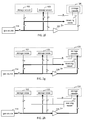
- the present methods use the well-known cascade dispensing approach.
- cascade dispensing the compressed gas is dispensed to a receiving vessel from multiple supply vessels in succession, where each succeeding supply vessel has an increasingly higher pressure of the compressed gas contained therein.
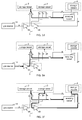
- FIGS. 1a-m illustrate an exemplary process flow diagram for carrying out the method.
- the lines and valves shown are only exemplary, and various alternative configurations could be used to carry out the first method.
- the dispensing system includes a gas source 14, which could be any suitable source for the compressed gas.
- the gas source 14 could be a hydrogen pipeline, a steam-hydrocarbon reformer, electrolyzer, tube trailer, liquid hydrogen supply, or the like.
- the first method is particularly suitable for relatively low pressure hydrogen sources like pipelines, electrolyzers, or reformers.
- the dispensing system comprises a first plurality of storage vessels 2, 3.
- the first plurality of storage vessels 2, 3 may include any number of high pressure storage vessels.
- the pressure of compressed gas contained within the each of the first plurality of storage vessels 2, 3 can be the same as one another or different from one another.
- the high pressure storage vessels 2, 3 may have a maximum pressure rating of, for example, 50 MPa.
- the dispensing system also comprises a second plurality of storage vessels 4.
- the second plurality of storage vessels 4 may include any number of high pressure storage vessels.
- the pressure of compressed gas contained within the each of the second plurality of storage vessels 4 can be the same as one another or different from one another.
- the second plurality of storage vessels may have a greater maximum pressure rating than the first plurality of storage vessels, for example, 90 MPa.
- the dispensing system also comprises gas compressing means 5, which can be a multistage compressor 5A, 5B and/or multiple compressors 5A, and 5B.
- the first plurality of storage vessels 2, 3 are charged with compressed gas from the gas source 14. This can be accomplished in any number of ways.
- a first storage vessel 2 of the first plurality of storage vessels can be charged from the gas source 14 by compressing the compressed gas in the gas compressing means 5A, and passing the compressed gas to the first storage vessel 2 of the first plurality of storage vessels.
- a second storage vessel 3 of the first plurality of storage vessels can be charged from the gas source 14 by compressing the compressed gas in the gas compressing means 5A, and passing the compressed gas to the second storage vessel 3.
- Priority may be given to charge one of the vessels of the first plurality of storage vessels, for example storage vessel 3, before charging the other of the first plurality of storage vessels in order to maintain the storage vessel having priority at near its desired maximum pressure.
- Additional storage vessels of the first plurality of storage vessels can likewise be charged with compressed gas from the gas source 14.
- multiple storage vessels of the first plurality of storage vessels can be charged simultaneously as shown in FIG. 1c .
- Dispensing to the receiving vessel 11 may be achieved using the well-known cascade dispensing technique.
- Compressed gas may be dispensed from a first storage vessel 2 of the first plurality of storage vessels to the receiving vessel 11 as shown in FIG. 1d .
- Compressed gas may be transferred from the first storage vessel 2 of the first plurality of storage vessels using a pressure difference between the first storage vessel 2 and the receiving vessel 11 without the use of a compressor. The transfer of the compressed gas may continue until the pressure difference between the two vessels is decreased to a desired amount.
- compressed gas may be simultaneously dispensed from the gas source 14 via the gas compressing means 5A to the receiving vessel 11.
- compressed gas may be withdrawn from a second storage vessel 3 of the first plurality of storage vessels, passed to compressing means 5B, and introduced into one or more of the second plurality of storage vessels 4.
- the storage vessel of the first plurality of storage vessels used to supply compressed gas to compressing means 5B for charging one or more of the second plurality of storage vessels 4 may be the storage vessel of the first plurality of storage vessels having priority for being charged.
- the system may be designed so that only the storage vessel of the first plurality of storage vessels having priority for being charged is available as a source to the compressing means 5B.
- compressed gas from a second storage vessel 3 of the first plurality of storage vessels may be compressed to charge one or more of the second plurality of storage vessels 4.
- the second storage vessel 3 may be the storage vessel having priority for being charged from the gas source 14 via compressing means 5A.
- compressed gas may be dispensed from a second storage vessel 3 of the first plurality of storage vessels to the receiving vessel 11 as shown in FIG. 1 h.
- the second storage vessel at the beginning of dispensing to the receiving vessel 11 contains the compressed gas at a higher pressure than the first storage vessel at the end of dispensing to the receiving vessel 11, thereby permitting further transfer of the compressed gas into the receiving vessel 11 using a pressure difference driving force.
- Compressed gas may be transferred from the second storage vessel 3 of the first plurality of storage vessels using a pressure difference between the second storage vessel 3 and the receiving vessel 11 without the use of a compressor.
- the transfer of the compressed gas may continue until the pressure difference between the two vessels is decreased to a desired amount.
- FIG. 1i illustrates two possible scenarios depending on the pressure of the compressed gas in storage vessel 3 and the pressure of the compressed gas in the receiving vessel 11.
- the pressure of the compressed gas in the storage vessel 3 and the receiving vessel 11 are the same.
- compressed gas from the gas source 14 is divided, with a first portion being charged into the second storage vessel 3 of the first plurality of storage vessels and a second portion charged into the receiving vessel 11.
- the pressure of the compressed gas in the second storage vessel 3 is greater than the pressure of the compressed gas in the receiving vessel 11.
- compressed gas from the gas source14 is blended with compressed gas from the second storage vessel 3 of the first plurality of storage vessels and the blended compressed gas is dispensed into the receiving vessel 11.
- the first dispensing method may proceed with corresponding steps using other storage vessels of the first plurality of storage vessels. While, in the figures only two storage vessels are shown for the first plurality of storage vessels, the first plurality of storage vessels may comprise two or more storage vessels. Dispensing using the cascade filling technique may use any number of the first plurality of storage vessels.
- compressed gas from the second storage vessel 3 of the first plurality of storage vessels and the gas source via compressing means 5A may be fed to the gas compressing means 5B and the compressed gas from the gas compressing means 5B passed to one or more of the second plurality of storage vessels 4.
- Using compressed gas from the second storage vessel 3 having compressed gas at a higher pressure than the gas source 14 facilitates the ability to maintain much higher pressures in at least one of the second plurality of storage vessels 4.
- compressed gas from gas source 14 is compressed in compressing means 5A with a portion charged into the second storage vessel 3 of the first plurality of storage vessels and another portion compressed in compressing means 5B and charged into one or more of the second plurality of storage vessels 4 without compressed gas being dispensed to the receiving vessel 11.
- compressed gas compressed in compressing means 5A is blended with compressed gas from the second storage vessel 3 of the first plurality of storage vessels, compressed in compressing means 5B and charged into one or more of the second plurality of storage vessels 4 without compressed gas being dispensed to the receiving vessel 11.
- compressed gas from the second storage vessel 3 of the first plurality of storage vessels may be passed to the gas compressing means 5B and the compressed gas from the gas compressing means 5B charged into the receiving vessel 11.
- Cascade filling of the receiving vessel 11 may then continue with dispensing from one or more of the second plurality of storage vessels 4 as shown in FIG. 1l .
- One or more cascade filling steps may be performed depending on how many second plurality of storage vessels 4 there are.
- compressed gas may be simultaneously dispensed from the second storage vessel 3 of the first plurality of storage vessels via the gas compressing means 5B to the receiving vessel 11.
- the compressing means 5A or 5B does not supply compressed gas to the receiving tank 11 from a gas source (i.e. one that is different from the gas source 14) constituted by any of the first plurality of storage vessels during any part of dispensing (pressure balancing) from another storage vessel of the first plurality of storage vessels, where the first plurality of storage vessels are successively used as sources by the compressing means 5A or 5B after being used for pressure balancing with the receiving vessel 11.
- a gas source i.e. one that is different from the gas source 14
- the gas source to the compressing means 5 never includes any of the other of the first plurality of storage vessels.
- This dispensing method does not include a step where the compressor supplies compressed gas to the receiving vessel 11 from the gas source 14 including one of the first plurality of storage vessels 2, 3 during any part of pressure balancing between another of the first plurality of storage vessels 2, 3 and the receiving vessel 11, where each of the first plurality of storage vessels 2, 3 is successively used as the gas source 14 by the compressing means 5 after being used for pressure balancing with the receiving vessel 11.
- the priority vessel only one of the storage vessels of the first plurality of storage vessels (the priority vessel) is used as a source to the compressing means 5B for charging compressed gas into the one or more storage vessels of the second plurality of storage vessels 4. Consequently, two or more of the first plurality of storage vessels are not successively used as the gas source by any compressing means.
- This feature where compressed gas from the storage vessels 4 is not used as a source by the gas compressing means 5 is a feature that characterizes the second plurality of storage vessels 4 from the first plurality of storage vessels 2, 3.
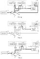
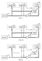
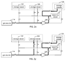
- FIGS. 2a-y illustrate an exemplary process flow diagram for carrying out the second method.
- the lines and valves shown are only exemplary, and various configurations could be used to carry out the second method. Quantities of gas are transferred via the various steps.
- the dispensing system includes a high pressure gas source 114, which could be any suitable high pressure source for the compressed gas.
- the high pressure gas source 114 could be a hydrogen tube trailer, or the like.
- the second method is particularly suitable for relatively high pressure hydrogen sources like tube trailers.
- the high pressure gas source 114 may be mobile, meaning that the high pressure gas source 114 may be filled at a compressed gas depot, brought to the compressed gas dispensing station, offloaded at the dispensing station, and then returned again to the compressed gas depot for refilling.
- the dispensing system comprises a first plurality of storage vessels 102, 103. While only two storage vessels are shown, the first plurality of storage vessels 102, 103 may include any number of high pressure storage vessels.
- the high pressure storage vessels 102, 103 may have a maximum pressure rating of, for example, 50 MPa.
- the first plurality of storage vessels 102, 103 may be fixed at the compressed gas dispensing station.
- the first plurality of storage vessels 102, 103 are intended to be fixed at the dispensing station and compressed gas transferred to the first plurality of storage vessels from a gas source, rather than the first plurality of storage vessels themselves being transported to a compressed gas depot for refilling.
- the dispensing system also comprises a second plurality of storage vessels 104.
- the second plurality of storage vessels 104 may include any number of high pressure storage vessels.
- the second plurality of storage vessels may have a maximum pressure rating of, for example, 90 MPa.
- the second plurality of storage vessels 104 may be fixed at the compressed gas dispensing station.
- the second plurality of storage vessels 104 are intended to be fixed at the dispensing station and compressed gas transferred to the second plurality of storage vessels from a gas source, rather than the second plurality of storage vessels themselves being transported to a compressed gas depot for refilling.
- the dispensing system also comprises gas compressing means 105, which can be a single stage compressor, a multistage compressor, or multiple compressors.
- the first plurality of storage vessels 102, 103 are charged with compressed gas from the high pressure gas source 114.
- the high pressure gas source 114 may comprise a plurality of storage vessels containing the compressed gas at high pressure as is the case for a tube trailer.
- a first storage vessel 102 of the first plurality of storage vessels can be charged from the high pressure gas source 114 using a pressure difference between one or more of the storage vessels of the high pressure gas source 114 and the first storage vessel 102 of the first plurality of storage vessels.
- the transfer of the compressed gas may continue until the pressure difference between the one or more storage vessels of the high pressure gas source 114 and the first storage vessel 102 of the first plurality of storage vessels is decreased to a desired amount.
- No compressor is used to transfer the compressed gas from the high pressure gas source 114 and the first storage vessel 102 of the first plurality of storage vessels.
- the dispensing system for the second method may be operatively configured such that the gas compressing means 105 is not suitable for compressing the compressed gas from the high pressure gas source 114 and transferring the compressed from the gas compressing means to any of the first plurality of storage vessels.
- compressed gas may be simultaneously passed from the high pressure gas source 114 to the gas compressing means 105, and from the gas compressing means 105 to one or more of the second plurality of storage vessels 104.
- FIG. 2c A preferred step in the second method is shown in FIG. 2c .
- this step while compressed gas is being charged into the first storage vessel 102, compressed gas is simultaneously being dispensed from the gas source 114 to the receiving vessel 111.
- This solves a problem in prior art methods where the dispensing station is taken offline and not used for dispensing to receiving vessels when the storage vessels are being charged from the gas source 114.
- FIG. 2d shows an additional or alternative preferred step in the second method that also solves the problem in prior art methods where the dispensing station is taken offline and not used for dispensing to receiving vessels when the storage vessels are being charged from the gas source 114.
- this step while compressed gas is being charged into the first storage vessel 102 and being charged into one or more of the second plurality of storage vessels 104 via the compressing means 105, compressed gas is simultaneously being dispensed from the gas source 114 to the receiving vessel 111.
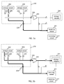
- Additional storage vessels of the first plurality of storage vessels can be charged from the high pressure gas source 114 as shown in FIG. 2e .
- a second storage vessel 103 of the first plurality of storage vessels may be charged from the high pressure gas source 114 using a pressure difference between one or more of the storage vessels of the high pressure gas source 114 and the second storage vessel 103 of the first plurality of storage vessels.
- the transfer of the compressed gas may continue until the pressure difference between the one or more storage vessels of the high pressure gas source 114 and the second storage vessel 103 of the first plurality of storage vessels is decreased to a desired amount.
- No compressor is used to transfer the compressed gas from the high pressure gas source 114 to the second storage vessel 103 of the first plurality of storage vessels.
- No compressor is used to transfer the compressed gas from the high pressure gas source 114 to any of the first plurality of storage vessels.
- the dispensing system for the second method may be operatively configured such that the gas compressing means 105 is not suitable for compressing the compressed gas from the high pressure gas source 114 and transferring the compressed gas from the gas compressing means to any of the first plurality of storage vessels 102, 103.
- FIG. 2f shows an additional or alternative preferred step in the second method that also solves the problem in prior art methods where the dispensing station is taken offline and not used for dispensing to receiving vessels when the storage vessels are being charged from the gas source 114.
- this step while compressed gas is being charged into the second storage vessel 103 of the first plurality of storage vessels, compressed gas is simultaneously being dispensed from the gas source 114 to the receiving vessel 111.
- FIG. 2g shows an additional or alternative preferred step in the second method that also solves the problem in prior art methods where the dispensing station is taken offline and not used for dispensing to receiving vessels when the storage vessels are being charged from the gas source 114.
- this step while compressed gas is being charged into the second storage vessel 103 of the first plurality of storage vessels and being charged into one or more of the second plurality of storage vessels 104 via the compressing means 105, compressed gas is simultaneously being dispensed from the gas source 114 to the receiving vessel 111.
- compressed gas may be simultaneously passed from the high pressure gas source 114 to the gas compressing means 105, and from the gas compressing means 105 to one or more of the second plurality of storage vessels 104.
- compressed gas may be dispensed from the high pressure gas source 114 to the receiving vessel 111 as shown in FIG. 2i .
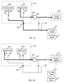
- Compressed gas may be dispensed from the fixed compressed gas storage at the compressed gas dispensing station. As shown in FIG. 2j , compressed gas may be dispensed from a first storage vessel 102 of the first plurality of storage vessels to the receiving vessel 111. Compressed gas may be transferred from the first storage vessel 102 of the first plurality of storage vessels using a pressure difference between the first storage vessel 102 and the receiving vessel 111 without the use of a compressor. The transfer of the compressed gas may continue until the pressure difference between the two vessels is decreased to a desired amount.
- compressed gas may be simultaneously dispensed from the high pressure gas source 114 if the pressure of the compressed gas in the high pressure gas source 114 is sufficient.
- compressed gas from the high pressure gas source 114 may be compressed to charge one or more of the second plurality of storage vessels 104.
- compressed gas from the first storage vessel 102 of the first plurality of storage vessels may also be compressed in gas compression means 105 and passed to one or more of the storage vessels of the second plurality of storage vessels 104 as shown in FIG. 2m .
- compressed gas from the first storage vessel 102 of the first plurality of storage vessels may be compressed in gas compression means 105 and passed to one or more of the storage vessels of the second plurality of storage vessels 104 as shown in FIG. 2n .
- compressed gas may be dispensed from a second storage vessel 103 of the first plurality of storage vessels to the receiving vessel 111 as shown in FIG. 2o .
- the second storage vessel 103 at the beginning of dispensing to the receiving vessel 111 contains the compressed gas at a higher pressure than the first storage vessel 102 at the end of dispensing to the receiving vessel 111.
- Compressed gas may be transferred from the second storage vessel 103 of the first plurality of storage vessels using a pressure difference between the second storage vessel 103 and the receiving vessel 111 without the use of a compressor.
- the transfer of the compressed gas may continue until the pressure difference between the two vessels is decreased to a desired amount.
- compressed gas from the high pressure gas source 114 may be blended with the compressed gas from the second storage vessel 103 of the first plurality of storage vessel and is charged into the receiving vessel 111, as shown in FIG. 2p .
- compressed gas from the high pressure source 114 may additionally be passed to the gas compressing means 105 and then charged into one or more of the second plurality of storage vessels 104.
- compressed gas from the second storage vessel 103 of the first plurality of storage vessels may be fed to the gas compressing means 105 and the compressed gas from the gas compressing means passed to one or more of the second plurality of storage vessels 104.
- compressed gas from the second storage vessel 103 having compressed gas at a high pressure facilitate the ability to maintain much higher pressure in at least one of the second plurality of storage vessels 104.
- compressed gas from the second storage vessel 103 of the first plurality of storage vessels may be compressed in gas compression means 105 and passed to one or more of the storage vessels of the second plurality of storage vessels 104 as shown in FIG. 2s .
- the dispensing method may proceed with corresponding steps using other storage vessels of the first plurality of storage vessels.
- At no time during dispensing from one of the first plurality of storage vessels is compressed gas simultaneously withdrawn from more than one of the first plurality of storage vessels.
- the compressor does not supply compressed gas to the receiving tank 111 from a gas source including any of the first plurality of storage vessels during any part of dispensing from another storage vessel of the first plurality of storage vessels.
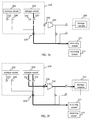
- compressed gas from the second storage vessel 103 of the first plurality of storage vessels may be compressed in the gas compressing means 105 and passed to the receiving vessel 111.
- compressed gas from the high pressure gas source 114 may be blended with the compressed gas from the second storage vessel 103 of the first plurality of storage vessel, compressed in gas compressing means 105 and charged into the receiving vessel 111, as shown in FIG. 2u .
- Cascade filling of the receiving vessel 111 may then continue with dispensing from one or more of the second plurality of storage vessels 104 as shown in FIG. 2v .
- One or more cascade filling steps may be performed depending on how many second plurality of storage vessels 104 there are.
- compressed gas may be simultaneously dispensed from the second storage vessel 103 of the first plurality of storage vessels via the gas compressing means 105 to the receiving vessel 111.
- compressed gas may be simultaneously dispensed from the high pressure gas source 114 via the gas compressing means 105 to the receiving vessel 111 while compressed gas is being dispensed from one or more of the storage vessels of the second plurality of storage vessels 104 to the receiving vessel 111, as shown in FIG. 2x .
- compressed gas from the second storage vessel 103 and the high pressure gas source 114 may be blended, compressed in gas compressing means 105, and charged into the receiving vessel 111 simultaneous with compressed gas from one or more of the storage vessels of second plurality of storage vessels 104, as shown in FIG. 2y .
- This feature where compressed gas from the storage vessels is not used as a source by the gas compressing means 105 is a feature that characterizes the second plurality of storage vessels 104 from the first plurality of storage vessels 102, 103.
- a first quantity of gas from at least one of a first plurality of storage vessels 102, 103 or a gas source 114 is transferred to at least one storage vessel of a second plurality of storage vessels 104 via a compressor 105 according to one or more of the steps shown in FIGS. 2b , 2d , 2g, 2h , 2l, 2m , 2n , 2q , 2r, and 2s .
- a second quantity of gas from the gas source 114 is transferred to a storage vessel of the first plurality of storage vessels 102, 103 using a pressure difference between the gas in the gas source 114 and the gas in the storage vessel to transfer the second quantity of gas while simultaneously transferring a third quantity of gas from the gas source 114 to the receiving vessel 111 using a respective pressure difference between the gas in the gas source 114 and the gas in the receiving vessel 111 to transfer the third quantity of gas.
- This may be accomplished according to one or more of the steps shown in FIGS. 2c, 2d , 2f, and 2g .
- the transfer of the first quantity of gas may be simultaneous with the transfer of the second quantity and third quantity of gas as shown in FIGS. 2d and 2g .
- a fourth quantity of gas from the at least one storage vessel of the second plurality of storage vessels 104 is transferred to the receiving vessel 111 using a pressure difference between the gas in the at least one storage vessel of the second plurality of storage vessels 104 and the gas in the receiving vessel 111 to transfer the fourth quantity of gas. This may be accomplished according to one or more of the steps shown in FIGS. 2v, 2w , 2x, and 2y .
- the second method may comprise transferring a fifth quantity of gas from a second storage vessel 103 of the first plurality of storage vessels to the receiving vessel 111 using a pressure difference between the gas in the second storage vessel 103 of the first plurality of storage vessels and the gas in the receiving vessel 111. This may be accomplished according to one or more of the steps shown in FIGS. 2o, 2p, 2q , and 2r .
- the second method may comprise transferring a sixth quantity of gas from the second storage vessel 103 to the receiving vessel 111 via compressor 105 simultaneous with the transfer of the fourth quantity of gas from a storage vessel of the second plurality of storage vessels 104 to the receiving vessel by a pressure difference. This may be accomplished according to one or more of the steps shown in FIGS. 2w and 2y .
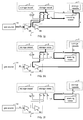
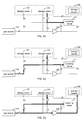
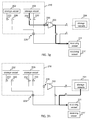
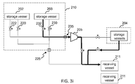
- FIGS. 3a-i illustrate an exemplary process flow diagram for carrying out the third method.
- the piping and valves shown are only exemplary, and various configurations could be used to carry out the third method. Quantities of gas are transferred via the various steps.
- the dispensing station comprises a mobile compressed gas storage device 210 comprising a plurality of storage vessels 202, 203.
- Each of the plurality of storage vessels 202, 203 have a control valve 220 (for 202), 230 (for 203) associated therewith for dispensing gas from each respective storage vessel to the receiving vessel 211 using a pressure difference between the gas in the respective storage vessel and the gas in the receiving vessel 211.
- the plurality of storage vessels 202, 203 may include any number of high pressure storage vessels.
- the high pressure storage vessels 202, 203 may have a maximum pressure rating of, for example, 50 MPa or 90 MPa.
- the mobile compressed gas storage device 210 is mobile, meaning that the mobile compressed gas storage device 210 may be filled at a compressed gas depot, brought to the compressed gas dispensing station, used as a source of compressed gas at the compressed gas dispensing station, and after the compressed gas is depleted, returned again to the compressed gas depot for refilling.
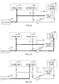
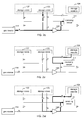
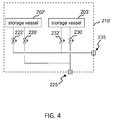
- the mobile compressed gas storage device 210 may be designed and configured to be readily swapped out with another mobile compressed gas storage device 210', shown in FIG. 4 , upon being depleted of compressed gas.
- the second mobile compressed gas storage device 210' has a plurality of storage vessels 202', 203', pipes, valves 220', 222', 230', 232', and connectors associated therewith.
- the dispensing station may be operated using more than one mobile compressed gas storage device 210 at a time and when cascade dispensing to a receiving vessel, may withdraw from more than one mobile compressed gas storage device when dispensing to the receiving vessel as described in US 8,453,682 .
- the dispensing station comprises fixed dispensing station components.
- the fixed dispensing station components comprise a compressing means 205, and one or more fixed storage vessels 204.
- the compressing means can be a single stage compressor, a multistage compressor, or multiple compressors.
- the compressing means 205 is operatively disposed to receive gas from each of the plurality of storage vessels of the mobile compressed gas storage device 210.
- the one or more fixed storage vessels 204 are operatively disposed to receive gas from the compressing means 205 and operatively disposed to dispense gas to the receiving vessel 211.
- the one or more fixed storage vessels 204 may include any number of high pressure storage vessels.
- the one or more fixed storage vessels may have a maximum pressure rating of, for example, 90 MPa.
- the one or more fixed storage vessels 204 are fixed at the compressed gas dispensing station.
- the one or more fixed storage vessels 204 may be charged with gas from one or more mobile compressed gas storage devices.
- the mobile compressed gas storage device 210 arrives at the dispensing station charged with compressed gas.
- the gas compressing means 205 is not used to charge any of the storage vessels 202, 203 of the mobile compressed gas storage device 210.
- All of the control valves 220, 230 associated with the plurality of storage vessels 202, 203 for dispensing to the receiving vessel 211 may be fixed on the mobile compressed gas storage device 210. All of the control valves 220, 230 associated with the plurality of storage vessels for dispensing to the receiving vessel 211 may be operatively disposed to feed a common connector 225 connecting the mobile compressed gas storage device 210 to the fixed dispensing station components.
- Each of the plurality of storage vessels 202, 203 may have a control valve 222 (for 202), 232 (for 203) associated therewith for transferring gas from each respective storage vessel to the compressing means 205. All of the control valves 222, 232 for transferring gas to the compressing means 205 may be fixed on the mobile compressed gas storage device 210. All of the control valves 222, 232 for transferring gas to the compressing means 205 may be operatively disposed to feed a common connector 235 connecting the mobile compressed gas storage device 210 to the fixed dispensing station components.
- each of the control valves is part of the fixed dispensing station components
- each of the plurality of storage vessels would need to be connected separately to the fixed dispensing station components, thereby increasing the number of high pressure connections. Reducing the number of high pressure connections decreases the risk of gas leaks.
- Compressed gas may be dispensed from the mobile compressed gas storage device 210 at the compressed gas dispensing station. As shown in FIG. 3a , compressed gas may be dispensed from a first storage vessel 202 of the plurality of storage vessels of the mobile compressed gas storage device 210 to the receiving vessel 211. Compressed gas may be transferred from the first storage vessel 202 of the plurality of storage vessels using a pressure difference between the first storage vessel 202 and the receiving vessel 211 without the use of a compressor. The transfer of the compressed gas may continue until the pressure difference between the two vessels is decreased to a desired amount.
- compressed gas from the first storage vessel 202 of the plurality of storage vessels may also be compressed in gas compression means 205 and passed to one or more of the fixed storage vessels 204 as shown in FIG. 3b .
- compressed gas from the second storage vessel 203 of the plurality of storage vessels may be compressed in gas compression means 205 and passed to one or more of the fixed storage vessels 204 as shown in FIG. 3c .
- Compressed gas from the mobile compressed gas storage device 210 is compressed in gas compression means 205 to form the higher pressure compressed gas in the one or more fixed storage vessels 204.
- compressed gas from the first storage vessel 202 of the plurality of storage vessels may be compressed in gas compression means 205 and passed to the one or more fixed storage vessels 204 as shown in FIG. 3d .
- compressed gas from any of the storage vessels of the plurality of storage vessels of the on the mobile compressed gas storage device 210 can be compressed in gas compression means 205 and passed to one or more of the fixed storage vessels 204 even during a period when no compressed gas is being dispensed to a receiving vessel 211.
- compressed gas may be dispensed from a second storage vessel 203 of the plurality of storage vessels to the receiving vessel 211 as shown in FIG. 3e .
- the second storage vessel 203 at the beginning of dispensing to the receiving vessel 211 contains the compressed gas at a higher pressure than the first storage vessel 202 at the end of dispensing to the receiving vessel 211.
- Compressed gas may be transferred from the second storage vessel 203 of the plurality of storage vessels using a pressure difference between the second storage vessel 203 and the receiving vessel 211.
- the transfer of the compressed gas may continue until the pressure difference between the two vessels is decreased to a desired amount.
- the dispensing method may proceed with corresponding steps using other storage vessels of the plurality of storage vessels on the mobile compressed gas storage device 210.
- At no time during dispensing from one of the plurality of storage vessels is compressed gas simultaneously withdrawn from another of the plurality of storage vessels of the mobile compressed gas storage device 210 where the compressed gas from both of storage vessels is passed to the receiving tank 211.
- the compressor does not supply compressed gas to the receiving tank 211 from a gas source including any of the plurality of storage vessels of the mobile compressed gas storage device during any part of dispensing from another storage vessel of the mobile compressed gas storage device.
- compressed gas from the second storage vessel 203 of the first compressed gas storage device may be fed to the gas compressing means 205 and the compressed gas from the gas compressing means 205 passed to one or more of the fixed storage vessels 204.
- compressed gas from the second storage vessel 203 having compressed gas at a high pressure facilitate the ability to maintain much higher pressure in at least one of the fixed storage vessels 204.
- compressed gas from the second storage vessel 203 of the mobile compressed gas storage device may be compressed in the gas compressing means 205 and passed to the receiving vessel 211.
- Cascade filling of the receiving vessel 211 may then continue with dispensing from one or more of the fixed storage vessels 204 as shown in FIG. 3h .
- One or more cascade filling steps may be performed depending on how many fixed storage vessels 204 there are.
- compressed gas may be simultaneously dispensed from the second storage vessel 203 of the mobile compressed gas storage device via the gas compressing means 205 to the receiving vessel 211.
- This feature where compressed gas from the storage vessels is not used as a source by the gas compressing means 205 is a feature that characterizes the one or more fixed storage vessels 204 from the plurality of storage vessels 202, 203 on the mobile compressed gas storage device 210.
- a first quantity of gas from a first storage vessel 202 of a plurality of storage vessels on a first mobile compressed gas storage device 210 is transferred to a receiving vessel 211 using a pressure difference between the gas in the first storage vessel 202 and the gas in the receiving vessel 211 to transfer the first quantity of gas. This may be accomplished according to one or more of the steps shown in FIGS. 3a, 3b , and 3c .
- a second quantity of gas from a second storage vessel 203 of the plurality of storage vessels on the first mobile compressed gas storage device 210 is transferred to the receiving vessel 211 using a pressure difference between the gas in the second storage vessel 203 and the gas in the receiving vessel 211 to transfer the second quantity of gas. This may be accomplished according to one or more of the steps shown in FIGS. 3e, and 3f .
- a third quantity of gas from at least one of the plurality of storage vessels on the first mobile compressed gas storage device 210 is transferred to one or more fixed storage vessels 204 via a compressor 205. This may be accomplished according to one or more of the steps shown in FIGS. 3b , 3c , 3d , and 3f .
- a fourth quantity of the gas from at least one of the one or more fixed storage vessels 204 is transferred to the receiving vessel 211 using a pressure difference between the gas in the at least one of the one or more fixed storage vessels 204 and the gas in the receiving vessel 211 to transfer the fourth quantity of gas, wherein the fourth quantity of gas comprises at least a portion of the third quantity of gas.
- This may be accomplished according to one or more of the steps shown in FIGS. 3h or 3i .
- the first mobile compressed gas storage device is transported to a refilling station after the first mobile compressed gas storage device 210 has been depleted to a selected depletion level.
- the first mobile compressed gas storage device is refilled at the refilling station.
- the first mobile compressed gas storage device is replaced at the dispensing station with a second mobile compressed gas storage device 210' as shown in FIG. 4 .
- a fifth quantity of the gas from a first storage vessel 202' of a plurality of storage vessels on the second mobile compressed gas storage device 210' is transferred to a second receiving vessel 211' using a pressure difference between the gas in the first storage vessel 202' of the plurality of storage vessels on the second mobile compressed gas storage device 210' and the gas in the second receiving vessel 211' to transfer the fifth quantity of gas.
- This may be accomplished according to one or more of the steps shown in FIGS. 3a, 3b , and 3c , where the second mobile compressed gas storage device 210' replaces the first mobile compressed gas storage device 210 in each of the respective figures and the second receiving vessel 211' replaces the first receiving vessel 211.
- a sixth quantity of the gas from the second storage vessel 203' of the plurality of storage vessels on the second mobile compressed gas storage device 210' is transferred to the second receiving vessel 211' using a pressure difference between the gas in the second storage vessel 203' of the plurality of storage vessels on the second mobile compressed gas storage device 210' and the gas in the second receiving vessel 211' to transfer the sixth quantity of gas.
- This may be accomplished according to one or more of the steps shown in FIGS. 3e, and 3f , where the second mobile compressed gas storage device 210' replaces the first mobile compressed gas storage device 210 in each of the respective figures and the second receiving vessel 211' replaces the first receiving vessel 211.
- a seventh quantity of the gas from at least one of the plurality of storage vessels 202', 203' on the second mobile compressed gas storage device 210' is transferred to one or more of the fixed storage vessels 204 via a compressor 205.
- This may be accomplished according to one or more of the steps shown in FIGS. 3b , 3c , 3d , and 3f , where the second mobile compressed gas storage device 210' replaces the first mobile compressed gas storage device 210 in each of the respective figures and the second receiving vessel 211' replaces the first receiving vessel 211.
- an eighth quantity of the gas from the at least one or another of the one or more fixed storage vessels 204 is transferred to the second receiving vessel 211' using a pressure difference between the gas in the at least one or the other of the one or more fixed storage vessels 204 and the gas in the second receiving vessel 211' to transfer the eighth quantity of gas, wherein the eighth quantity of gas comprises at least a portion of the seventh quantity of gas.
- the at least one of the one or more fixed storage vessels providing the eighth quantity of gas may be the same or different as the at least one of the one or more fixed storage vessels providing the fourth quantity of gas. This may be accomplished according to one or more of the steps shown in FIGS. 3h , and 3i , where the second mobile compressed gas storage device 210' replaces the first mobile compressed gas storage device 210 in each of the respective figures and the second receiving vessel 211' replaces the first receiving vessel 211.
- a ninth quantity of the gas from the second storage vessel 203 of the first mobile compressed gas storage device may be transferred to the receiving vessel 211 via a compressor as shown in FIGS. 3g and 3i .
- the transfer of the ninth quantity of gas from the second storage vessel of the first mobile compressed gas storage device 210 may be transferred to the receiving vessel 211 simultaneous with the transfer of the fourth quantity of gas from the at least one of the one or more fixed storage vessels to the receiving vessel 211.
Landscapes
- Engineering & Computer Science (AREA)
- Mechanical Engineering (AREA)
- General Engineering & Computer Science (AREA)
- Filling Or Discharging Of Gas Storage Vessels (AREA)
Priority Applications (10)
| Application Number | Priority Date | Filing Date | Title |
|---|---|---|---|
| PL16170898T PL3249281T3 (pl) | 2016-05-23 | 2016-05-23 | Dozowanie sprężonego gazu |
| EP16170898.7A EP3249281B1 (fr) | 2016-05-23 | 2016-05-23 | Distribution de gaz comprimé |
| ES17162381T ES2837249T3 (es) | 2016-05-23 | 2017-03-22 | Distribución de gas comprimido |
| EP17162381.2A EP3249282B1 (fr) | 2016-05-23 | 2017-03-22 | Distribution de gaz comprimé |
| US15/465,723 US10508770B2 (en) | 2016-05-23 | 2017-03-22 | Compressed gas dispensing |
| CA2967600A CA2967600C (fr) | 2016-05-23 | 2017-05-17 | Distribution de gaz comprime |
| AU2017203304A AU2017203304B2 (en) | 2016-05-23 | 2017-05-17 | Compressed gas dispensing |
| JP2017098051A JP6416982B2 (ja) | 2016-05-23 | 2017-05-17 | 圧縮ガス分配方法及び圧縮ガス分配ステーション |
| KR1020170062860A KR101979083B1 (ko) | 2016-05-23 | 2017-05-22 | 압축 가스 분배 |
| CN201710368903.9A CN107420738B (zh) | 2016-05-23 | 2017-05-23 | 压缩气体分配 |
Applications Claiming Priority (1)
| Application Number | Priority Date | Filing Date | Title |
|---|---|---|---|
| EP16170898.7A EP3249281B1 (fr) | 2016-05-23 | 2016-05-23 | Distribution de gaz comprimé |
Publications (2)
| Publication Number | Publication Date |
|---|---|
| EP3249281A1 true EP3249281A1 (fr) | 2017-11-29 |
| EP3249281B1 EP3249281B1 (fr) | 2022-02-23 |
Family
ID=56072255
Family Applications (1)
| Application Number | Title | Priority Date | Filing Date |
|---|---|---|---|
| EP16170898.7A Active EP3249281B1 (fr) | 2016-05-23 | 2016-05-23 | Distribution de gaz comprimé |
Country Status (8)
| Country | Link |
|---|---|
| US (1) | US10508770B2 (fr) |
| EP (1) | EP3249281B1 (fr) |
| JP (1) | JP6416982B2 (fr) |
| KR (1) | KR101979083B1 (fr) |
| CN (1) | CN107420738B (fr) |
| AU (1) | AU2017203304B2 (fr) |
| CA (1) | CA2967600C (fr) |
| PL (1) | PL3249281T3 (fr) |
Cited By (8)
| Publication number | Priority date | Publication date | Assignee | Title |
|---|---|---|---|---|
| EP3517823A1 (fr) | 2018-01-25 | 2019-07-31 | Air Products and Chemicals, Inc. | Procédé de distribution de gaz combustible |
| WO2020103993A1 (fr) * | 2018-11-20 | 2020-05-28 | Nel Hydrogen A/S | Ravitaillement en hydrogène rapide et à volume élevé d'un véhicule utilitaire lourd |
| WO2020147911A1 (fr) * | 2019-01-18 | 2020-07-23 | Nel Hydrogen A/S | Station de ravitaillement en hydrogène à grande échelle |
| WO2020193922A1 (fr) | 2019-03-27 | 2020-10-01 | Mcphy Energy | Station de remplissage pour alimenter une pluralité de véhicules avec un gaz contenant de l'hydrogène |
| US10883664B2 (en) | 2018-01-25 | 2021-01-05 | Air Products And Chemicals, Inc. | Fuel gas distribution method |
| EP3985299A1 (fr) * | 2020-10-16 | 2022-04-20 | Air Liquide | Dispositif et procédé de remplissage de réservoirs de gaz sous pression |
| EP3855061A4 (fr) * | 2018-09-21 | 2022-05-25 | National Institute of Clean-and-Low-Carbon Energy | Système et procédé de commande de station de remplissage d'hydrogène, et station de remplissage d'hydrogène |
| US11969365B2 (en) | 2019-04-02 | 2024-04-30 | Paillet Stephane | Sheath made of an elastomer material for a prosthesis liner, and custom-made sheath for a prosthesis |
Families Citing this family (8)
| Publication number | Priority date | Publication date | Assignee | Title |
|---|---|---|---|---|
| FR3091572B1 (fr) * | 2019-01-09 | 2020-12-11 | Air Liquide | Dispositif et procédé de remplissage de réservoirs de gaz sous pression |
| JP6600430B1 (ja) * | 2019-02-01 | 2019-10-30 | 岩谷産業株式会社 | 水素ガスディスペンサーの検査装置 |
| JP7252037B2 (ja) * | 2019-03-29 | 2023-04-04 | 株式会社キッツ | 水素ガスの充填方法と水素ステーション |
| US11105469B2 (en) * | 2019-03-29 | 2021-08-31 | Uchicago Argonne, Llc. | Integrated tube-trailer and stationary ground storage system and method for enhanced pressure consolidation operations for refueling of gaseous fuels |
| US20230137335A1 (en) | 2021-10-29 | 2023-05-04 | Air Products And Chemicals, Inc. | Hydrogen storage and dispensing apparatus and method |
| US12092093B2 (en) | 2022-03-08 | 2024-09-17 | Air Products And Chemicals, Inc. | Apparatus and method for cryogenic pump cooldown |
| US11946599B2 (en) | 2022-06-08 | 2024-04-02 | Air Products And Chemicals, Inc. | Apparatus and method for hydrogen fuel dispensing |
| EP4450863A1 (fr) | 2023-04-20 | 2024-10-23 | Air Products and Chemicals, Inc. | Appareil et procédé de distribution d'un fluide cryogénique |
Citations (12)
| Publication number | Priority date | Publication date | Assignee | Title |
|---|---|---|---|---|
| US5406988A (en) | 1993-12-01 | 1995-04-18 | Pacific Cryogenics, Inc. | Method and apparatus for dispensing compressed gas into a vehicle |
| US20040118476A1 (en) * | 2002-07-16 | 2004-06-24 | Borck Joachim George | Gas distribution system |
| EP1452794A2 (fr) * | 2003-02-21 | 2004-09-01 | Air Products And Chemicals, Inc. | Station autonome et mobile d'alimentation en fuel |
| US20090236006A1 (en) * | 2005-10-10 | 2009-09-24 | Air Products And Chemicals, Inc. | Temperature-Compensated Dispensing of Compressed Gases |
| US20100193070A1 (en) * | 2007-07-23 | 2010-08-05 | L'Air Liquide Societe Annoyme Pour L'Etude Et L'Exploitaaaaaation Des Procedes Georges Claude | Method for Filling a Tank with Pressurized Gas |
| US8453682B2 (en) | 2010-05-24 | 2013-06-04 | Air Products And Chemicals, Inc. | Compressed gas dispensing method |
| US20140261864A1 (en) * | 2013-03-14 | 2014-09-18 | Air Products And Chemicals, Inc. | Method for Dispensing Compressed Gases |
| EP2796762A1 (fr) * | 2013-04-22 | 2014-10-29 | Air Products and Chemicals, Inc. | Procédé et système de distribution de gaz à température régulée |
| US8899278B2 (en) | 2011-06-17 | 2014-12-02 | Air Products And Chemicals, Inc. | Pressure cycle management in compressed gas dispensing systems |
| US20140352840A1 (en) * | 2013-05-31 | 2014-12-04 | Nuvera Fuel Cells, Inc. | Distributed hydrogen refueling cascade method and system |
| WO2015004344A2 (fr) * | 2013-07-11 | 2015-01-15 | L'air Liquide, Societe Anonyme Pour L'etude Et L'exploitation Des Procedes Georges Claude | Procédé et station de remplissage de gaz |
| US20160116113A1 (en) * | 2014-10-28 | 2016-04-28 | CNG Services, LLC | Compressed gas delivery system |
Family Cites Families (7)
| Publication number | Priority date | Publication date | Assignee | Title |
|---|---|---|---|---|
| JP2984812B2 (ja) | 1994-10-08 | 1999-11-29 | 株式会社加地テック | ボンベへの圧縮燃料ガス充填方法及び装置 |
| DE10334055A1 (de) * | 2003-07-25 | 2005-02-10 | Linde Ag | Verfahren zum Betanken eines Fahrzeuges |
| FR2891347B1 (fr) | 2005-09-28 | 2007-11-02 | Air Liquide | Procede et dispositif de remplissage d'un gaz sous pression dans un reservoir |
| CN101327782A (zh) * | 2008-07-29 | 2008-12-24 | 四川金科环保科技有限公司 | Cng加气子站系统及其加气方法 |
| CN107842712B (zh) * | 2012-08-24 | 2021-10-15 | 奥斯康普控股公司 | 虚拟气态燃料管道 |
| JP5847885B2 (ja) | 2014-06-05 | 2016-01-27 | 川崎エンジニアリング株式会社 | 水素トレーラ |
| CN104534271B (zh) * | 2014-12-15 | 2016-05-18 | 清华大学 | 一种cng和hcng的混合加气装置及加气方法 |
-
2016
- 2016-05-23 PL PL16170898T patent/PL3249281T3/pl unknown
- 2016-05-23 EP EP16170898.7A patent/EP3249281B1/fr active Active
-
2017
- 2017-03-22 US US15/465,723 patent/US10508770B2/en active Active
- 2017-05-17 CA CA2967600A patent/CA2967600C/fr active Active
- 2017-05-17 AU AU2017203304A patent/AU2017203304B2/en active Active
- 2017-05-17 JP JP2017098051A patent/JP6416982B2/ja active Active
- 2017-05-22 KR KR1020170062860A patent/KR101979083B1/ko active IP Right Grant
- 2017-05-23 CN CN201710368903.9A patent/CN107420738B/zh active Active
Patent Citations (16)
| Publication number | Priority date | Publication date | Assignee | Title |
|---|---|---|---|---|
| US5406988A (en) | 1993-12-01 | 1995-04-18 | Pacific Cryogenics, Inc. | Method and apparatus for dispensing compressed gas into a vehicle |
| US20040118476A1 (en) * | 2002-07-16 | 2004-06-24 | Borck Joachim George | Gas distribution system |
| US6779568B2 (en) | 2002-07-16 | 2004-08-24 | General Hydrogen Corporation | Gas distribution system |
| EP1452794A2 (fr) * | 2003-02-21 | 2004-09-01 | Air Products And Chemicals, Inc. | Station autonome et mobile d'alimentation en fuel |
| US6786245B1 (en) | 2003-02-21 | 2004-09-07 | Air Products And Chemicals, Inc. | Self-contained mobile fueling station |
| US8156970B2 (en) | 2005-10-10 | 2012-04-17 | Air Products And Chemicals, Inc. | Temperature-compensated dispensing of compressed gases |
| US20090236006A1 (en) * | 2005-10-10 | 2009-09-24 | Air Products And Chemicals, Inc. | Temperature-Compensated Dispensing of Compressed Gases |
| US20100193070A1 (en) * | 2007-07-23 | 2010-08-05 | L'Air Liquide Societe Annoyme Pour L'Etude Et L'Exploitaaaaaation Des Procedes Georges Claude | Method for Filling a Tank with Pressurized Gas |
| EP2174057B1 (fr) | 2007-07-23 | 2011-03-16 | L'Air Liquide Société Anonyme pour l'Etude et l'Exploitation des Procédés Georges Claude | Proceeé de remplissage d'un gaz sous pression dans un reservoir |
| US8453682B2 (en) | 2010-05-24 | 2013-06-04 | Air Products And Chemicals, Inc. | Compressed gas dispensing method |
| US8899278B2 (en) | 2011-06-17 | 2014-12-02 | Air Products And Chemicals, Inc. | Pressure cycle management in compressed gas dispensing systems |
| US20140261864A1 (en) * | 2013-03-14 | 2014-09-18 | Air Products And Chemicals, Inc. | Method for Dispensing Compressed Gases |
| EP2796762A1 (fr) * | 2013-04-22 | 2014-10-29 | Air Products and Chemicals, Inc. | Procédé et système de distribution de gaz à température régulée |
| US20140352840A1 (en) * | 2013-05-31 | 2014-12-04 | Nuvera Fuel Cells, Inc. | Distributed hydrogen refueling cascade method and system |
| WO2015004344A2 (fr) * | 2013-07-11 | 2015-01-15 | L'air Liquide, Societe Anonyme Pour L'etude Et L'exploitation Des Procedes Georges Claude | Procédé et station de remplissage de gaz |
| US20160116113A1 (en) * | 2014-10-28 | 2016-04-28 | CNG Services, LLC | Compressed gas delivery system |
Cited By (14)
| Publication number | Priority date | Publication date | Assignee | Title |
|---|---|---|---|---|
| EP3517823A1 (fr) | 2018-01-25 | 2019-07-31 | Air Products and Chemicals, Inc. | Procédé de distribution de gaz combustible |
| US10883664B2 (en) | 2018-01-25 | 2021-01-05 | Air Products And Chemicals, Inc. | Fuel gas distribution method |
| EP3855061A4 (fr) * | 2018-09-21 | 2022-05-25 | National Institute of Clean-and-Low-Carbon Energy | Système et procédé de commande de station de remplissage d'hydrogène, et station de remplissage d'hydrogène |
| WO2020103993A1 (fr) * | 2018-11-20 | 2020-05-28 | Nel Hydrogen A/S | Ravitaillement en hydrogène rapide et à volume élevé d'un véhicule utilitaire lourd |
| WO2020147911A1 (fr) * | 2019-01-18 | 2020-07-23 | Nel Hydrogen A/S | Station de ravitaillement en hydrogène à grande échelle |
| US11913606B2 (en) | 2019-01-18 | 2024-02-27 | Nel Hydrogen A/S | Large-scale hydrogen refueling station |
| EP4310388A2 (fr) | 2019-03-27 | 2024-01-24 | McPhy Energy | Station de remplissage pour alimenter une pluralité de véhicules avec un gaz contenant de l'hydrogène |
| FR3094454A1 (fr) | 2019-03-27 | 2020-10-02 | Mcphy Energy | Station de remplissage pour alimenter une pluralité de véhicules avec un gaz contenant de l’hydrogène |
| WO2020193922A1 (fr) | 2019-03-27 | 2020-10-01 | Mcphy Energy | Station de remplissage pour alimenter une pluralité de véhicules avec un gaz contenant de l'hydrogène |
| EP4310388A3 (fr) * | 2019-03-27 | 2024-04-24 | McPhy Energy | Station de remplissage pour alimenter une pluralité de véhicules avec un gaz contenant de l'hydrogène |
| US12025278B2 (en) | 2019-03-27 | 2024-07-02 | Mcphy Energy | Filling station for supplying a plurality of vehicles with a gas containing hydrogen |
| US11969365B2 (en) | 2019-04-02 | 2024-04-30 | Paillet Stephane | Sheath made of an elastomer material for a prosthesis liner, and custom-made sheath for a prosthesis |
| FR3115347A1 (fr) * | 2020-10-16 | 2022-04-22 | L'air Liquide, Societe Anonyme Pour L'etude Et L'exploitation Des Procedes Georges Claude | Dispositif et procédé de remplissage de réservoirs de gaz sous pression |
| EP3985299A1 (fr) * | 2020-10-16 | 2022-04-20 | Air Liquide | Dispositif et procédé de remplissage de réservoirs de gaz sous pression |
Also Published As
| Publication number | Publication date |
|---|---|
| CA2967600A1 (fr) | 2017-11-23 |
| JP2017211085A (ja) | 2017-11-30 |
| EP3249281B1 (fr) | 2022-02-23 |
| AU2017203304A1 (en) | 2017-12-07 |
| KR20170132097A (ko) | 2017-12-01 |
| CN107420738B (zh) | 2020-04-21 |
| CN107420738A (zh) | 2017-12-01 |
| AU2017203304B2 (en) | 2018-08-30 |
| US20170336028A1 (en) | 2017-11-23 |
| JP6416982B2 (ja) | 2018-10-31 |
| US10508770B2 (en) | 2019-12-17 |
| KR101979083B1 (ko) | 2019-09-03 |
| PL3249281T3 (pl) | 2022-05-02 |
| CA2967600C (fr) | 2019-02-05 |
Similar Documents
| Publication | Publication Date | Title |
|---|---|---|
| EP3249281A1 (fr) | Distribution de gaz comprimé | |
| EP3249282B1 (fr) | Distribution de gaz comprimé | |
| US9074730B2 (en) | Method for dispensing compressed gases | |
| KR101593783B1 (ko) | 압축 가스를 분배하는 방법 | |
| CN109843728B (zh) | 用于降低加氢成本的双层管拖车操作方法和系统 | |
| US8453682B2 (en) | Compressed gas dispensing method | |
| CA3030724C (fr) | Methode de distribution de gaz carburant | |
| EP3263969B1 (fr) | Distribution de gaz comprimé | |
| US20160348841A1 (en) | Hydrogen dispensing apparatus | |
| EP3892910B1 (fr) | Dispositif de remplissage de réservoirs de gaz sous pression | |
| CN113631852A (zh) | 用于向多个交通工具供应包含氢的气体的填充站 | |
| JP6525754B2 (ja) | 液化天然ガス充填方法および装置 | |
| EP3517823A1 (fr) | Procédé de distribution de gaz combustible | |
| CN113513701A (zh) | 用于填充加压气体储罐的装置和方法 | |
| RU2237833C1 (ru) | Способ заправки баллонов и сосудов сжиженным нефтяным газом | |
| JP2023065806A (ja) | 水素ガス供給システム | |
| CN112460474A (zh) | Lng加注装置及加注方法 |
Legal Events
| Date | Code | Title | Description |
|---|---|---|---|
| PUAI | Public reference made under article 153(3) epc to a published international application that has entered the european phase |
Free format text: ORIGINAL CODE: 0009012 |
|
| STAA | Information on the status of an ep patent application or granted ep patent |
Free format text: STATUS: THE APPLICATION HAS BEEN PUBLISHED |
|
| AK | Designated contracting states |
Kind code of ref document: A1 Designated state(s): AL AT BE BG CH CY CZ DE DK EE ES FI FR GB GR HR HU IE IS IT LI LT LU LV MC MK MT NL NO PL PT RO RS SE SI SK SM TR |
|
| AX | Request for extension of the european patent |
Extension state: BA ME |
|
| STAA | Information on the status of an ep patent application or granted ep patent |
Free format text: STATUS: REQUEST FOR EXAMINATION WAS MADE |
|
| 17P | Request for examination filed |
Effective date: 20180529 |
|
| RBV | Designated contracting states (corrected) |
Designated state(s): AL AT BE BG CH CY CZ DE DK EE ES FI FR GB GR HR HU IE IS IT LI LT LU LV MC MK MT NL NO PL PT RO RS SE SI SK SM TR |
|
| STAA | Information on the status of an ep patent application or granted ep patent |
Free format text: STATUS: EXAMINATION IS IN PROGRESS |
|
| 17Q | First examination report despatched |
Effective date: 20191121 |
|
| STAA | Information on the status of an ep patent application or granted ep patent |
Free format text: STATUS: EXAMINATION IS IN PROGRESS |
|
| GRAP | Despatch of communication of intention to grant a patent |
Free format text: ORIGINAL CODE: EPIDOSNIGR1 |
|
| STAA | Information on the status of an ep patent application or granted ep patent |
Free format text: STATUS: GRANT OF PATENT IS INTENDED |
|
| INTG | Intention to grant announced |
Effective date: 20210914 |
|
| GRAS | Grant fee paid |
Free format text: ORIGINAL CODE: EPIDOSNIGR3 |
|
| GRAA | (expected) grant |
Free format text: ORIGINAL CODE: 0009210 |
|
| STAA | Information on the status of an ep patent application or granted ep patent |
Free format text: STATUS: THE PATENT HAS BEEN GRANTED |
|
| AK | Designated contracting states |
Kind code of ref document: B1 Designated state(s): AL AT BE BG CH CY CZ DE DK EE ES FI FR GB GR HR HU IE IS IT LI LT LU LV MC MK MT NL NO PL PT RO RS SE SI SK SM TR |
|
| REG | Reference to a national code |
Ref country code: GB Ref legal event code: FG4D |
|
| REG | Reference to a national code |
Ref country code: CH Ref legal event code: EP |
|
| REG | Reference to a national code |
Ref country code: DE Ref legal event code: R096 Ref document number: 602016069294 Country of ref document: DE |
|
| REG | Reference to a national code |
Ref country code: AT Ref legal event code: REF Ref document number: 1470728 Country of ref document: AT Kind code of ref document: T Effective date: 20220315 |
|
| REG | Reference to a national code |
Ref country code: IE Ref legal event code: FG4D |
|
| REG | Reference to a national code |
Ref country code: SE Ref legal event code: TRGR |
|
| REG | Reference to a national code |
Ref country code: NL Ref legal event code: FP |
|
| REG | Reference to a national code |
Ref country code: FI Ref legal event code: FGE |
|
| REG | Reference to a national code |
Ref country code: LT Ref legal event code: MG9D |
|
| REG | Reference to a national code |
Ref country code: NO Ref legal event code: T2 Effective date: 20220223 |
|
| PG25 | Lapsed in a contracting state [announced via postgrant information from national office to epo] |
Ref country code: RS Free format text: LAPSE BECAUSE OF FAILURE TO SUBMIT A TRANSLATION OF THE DESCRIPTION OR TO PAY THE FEE WITHIN THE PRESCRIBED TIME-LIMIT Effective date: 20220223 Ref country code: PT Free format text: LAPSE BECAUSE OF FAILURE TO SUBMIT A TRANSLATION OF THE DESCRIPTION OR TO PAY THE FEE WITHIN THE PRESCRIBED TIME-LIMIT Effective date: 20220623 Ref country code: LT Free format text: LAPSE BECAUSE OF FAILURE TO SUBMIT A TRANSLATION OF THE DESCRIPTION OR TO PAY THE FEE WITHIN THE PRESCRIBED TIME-LIMIT Effective date: 20220223 Ref country code: HR Free format text: LAPSE BECAUSE OF FAILURE TO SUBMIT A TRANSLATION OF THE DESCRIPTION OR TO PAY THE FEE WITHIN THE PRESCRIBED TIME-LIMIT Effective date: 20220223 Ref country code: ES Free format text: LAPSE BECAUSE OF FAILURE TO SUBMIT A TRANSLATION OF THE DESCRIPTION OR TO PAY THE FEE WITHIN THE PRESCRIBED TIME-LIMIT Effective date: 20220223 Ref country code: BG Free format text: LAPSE BECAUSE OF FAILURE TO SUBMIT A TRANSLATION OF THE DESCRIPTION OR TO PAY THE FEE WITHIN THE PRESCRIBED TIME-LIMIT Effective date: 20220523 |
|
| PG25 | Lapsed in a contracting state [announced via postgrant information from national office to epo] |
Ref country code: LV Free format text: LAPSE BECAUSE OF FAILURE TO SUBMIT A TRANSLATION OF THE DESCRIPTION OR TO PAY THE FEE WITHIN THE PRESCRIBED TIME-LIMIT Effective date: 20220223 Ref country code: GR Free format text: LAPSE BECAUSE OF FAILURE TO SUBMIT A TRANSLATION OF THE DESCRIPTION OR TO PAY THE FEE WITHIN THE PRESCRIBED TIME-LIMIT Effective date: 20220524 |
|
| PG25 | Lapsed in a contracting state [announced via postgrant information from national office to epo] |
Ref country code: IS Free format text: LAPSE BECAUSE OF FAILURE TO SUBMIT A TRANSLATION OF THE DESCRIPTION OR TO PAY THE FEE WITHIN THE PRESCRIBED TIME-LIMIT Effective date: 20220623 |
|
| PG25 | Lapsed in a contracting state [announced via postgrant information from national office to epo] |
Ref country code: SM Free format text: LAPSE BECAUSE OF FAILURE TO SUBMIT A TRANSLATION OF THE DESCRIPTION OR TO PAY THE FEE WITHIN THE PRESCRIBED TIME-LIMIT Effective date: 20220223 Ref country code: SK Free format text: LAPSE BECAUSE OF FAILURE TO SUBMIT A TRANSLATION OF THE DESCRIPTION OR TO PAY THE FEE WITHIN THE PRESCRIBED TIME-LIMIT Effective date: 20220223 Ref country code: RO Free format text: LAPSE BECAUSE OF FAILURE TO SUBMIT A TRANSLATION OF THE DESCRIPTION OR TO PAY THE FEE WITHIN THE PRESCRIBED TIME-LIMIT Effective date: 20220223 Ref country code: EE Free format text: LAPSE BECAUSE OF FAILURE TO SUBMIT A TRANSLATION OF THE DESCRIPTION OR TO PAY THE FEE WITHIN THE PRESCRIBED TIME-LIMIT Effective date: 20220223 Ref country code: DK Free format text: LAPSE BECAUSE OF FAILURE TO SUBMIT A TRANSLATION OF THE DESCRIPTION OR TO PAY THE FEE WITHIN THE PRESCRIBED TIME-LIMIT Effective date: 20220223 |
|
| REG | Reference to a national code |
Ref country code: DE Ref legal event code: R097 Ref document number: 602016069294 Country of ref document: DE |
|
| PG25 | Lapsed in a contracting state [announced via postgrant information from national office to epo] |
Ref country code: AL Free format text: LAPSE BECAUSE OF FAILURE TO SUBMIT A TRANSLATION OF THE DESCRIPTION OR TO PAY THE FEE WITHIN THE PRESCRIBED TIME-LIMIT Effective date: 20220223 |
|
| PLBE | No opposition filed within time limit |
Free format text: ORIGINAL CODE: 0009261 |
|
| STAA | Information on the status of an ep patent application or granted ep patent |
Free format text: STATUS: NO OPPOSITION FILED WITHIN TIME LIMIT |
|
| PG25 | Lapsed in a contracting state [announced via postgrant information from national office to epo] |
Ref country code: MC Free format text: LAPSE BECAUSE OF FAILURE TO SUBMIT A TRANSLATION OF THE DESCRIPTION OR TO PAY THE FEE WITHIN THE PRESCRIBED TIME-LIMIT Effective date: 20220223 Ref country code: LU Free format text: LAPSE BECAUSE OF NON-PAYMENT OF DUE FEES Effective date: 20220523 |
|
| 26N | No opposition filed |
Effective date: 20221124 |
|
| PG25 | Lapsed in a contracting state [announced via postgrant information from national office to epo] |
Ref country code: SI Free format text: LAPSE BECAUSE OF FAILURE TO SUBMIT A TRANSLATION OF THE DESCRIPTION OR TO PAY THE FEE WITHIN THE PRESCRIBED TIME-LIMIT Effective date: 20220223 |
|
| REG | Reference to a national code |
Ref country code: FR Ref legal event code: PLFP Year of fee payment: 8 |
|
| PG25 | Lapsed in a contracting state [announced via postgrant information from national office to epo] |
Ref country code: IE Free format text: LAPSE BECAUSE OF NON-PAYMENT OF DUE FEES Effective date: 20220523 |
|
| P01 | Opt-out of the competence of the unified patent court (upc) registered |
Effective date: 20230517 |
|
| PG25 | Lapsed in a contracting state [announced via postgrant information from national office to epo] |
Ref country code: IT Free format text: LAPSE BECAUSE OF FAILURE TO SUBMIT A TRANSLATION OF THE DESCRIPTION OR TO PAY THE FEE WITHIN THE PRESCRIBED TIME-LIMIT Effective date: 20220223 |
|
| PG25 | Lapsed in a contracting state [announced via postgrant information from national office to epo] |
Ref country code: HU Free format text: LAPSE BECAUSE OF FAILURE TO SUBMIT A TRANSLATION OF THE DESCRIPTION OR TO PAY THE FEE WITHIN THE PRESCRIBED TIME-LIMIT; INVALID AB INITIO Effective date: 20160523 |
|
| PG25 | Lapsed in a contracting state [announced via postgrant information from national office to epo] |
Ref country code: MK Free format text: LAPSE BECAUSE OF FAILURE TO SUBMIT A TRANSLATION OF THE DESCRIPTION OR TO PAY THE FEE WITHIN THE PRESCRIBED TIME-LIMIT Effective date: 20220223 Ref country code: CY Free format text: LAPSE BECAUSE OF FAILURE TO SUBMIT A TRANSLATION OF THE DESCRIPTION OR TO PAY THE FEE WITHIN THE PRESCRIBED TIME-LIMIT Effective date: 20220223 |
|
| PGFP | Annual fee paid to national office [announced via postgrant information from national office to epo] |
Ref country code: NL Payment date: 20240415 Year of fee payment: 9 |
|
| PGFP | Annual fee paid to national office [announced via postgrant information from national office to epo] |
Ref country code: PL Payment date: 20240229 Year of fee payment: 9 Ref country code: NO Payment date: 20240222 Year of fee payment: 9 Ref country code: FR Payment date: 20240328 Year of fee payment: 9 |
|
| PGFP | Annual fee paid to national office [announced via postgrant information from national office to epo] |
Ref country code: GB Payment date: 20240402 Year of fee payment: 9 |
|
| PGFP | Annual fee paid to national office [announced via postgrant information from national office to epo] |
Ref country code: DE Payment date: 20240326 Year of fee payment: 9 |
|
| PGFP | Annual fee paid to national office [announced via postgrant information from national office to epo] |
Ref country code: CH Payment date: 20240602 Year of fee payment: 9 |
|
| PGFP | Annual fee paid to national office [announced via postgrant information from national office to epo] |
Ref country code: AT Payment date: 20240425 Year of fee payment: 9 Ref country code: CZ Payment date: 20240429 Year of fee payment: 9 |
|
| PGFP | Annual fee paid to national office [announced via postgrant information from national office to epo] |
Ref country code: FI Payment date: 20240514 Year of fee payment: 9 |
|
| PGFP | Annual fee paid to national office [announced via postgrant information from national office to epo] |
Ref country code: SE Payment date: 20240328 Year of fee payment: 9 Ref country code: BE Payment date: 20240422 Year of fee payment: 9 |
|
| PG25 | Lapsed in a contracting state [announced via postgrant information from national office to epo] |
Ref country code: MT Free format text: LAPSE BECAUSE OF FAILURE TO SUBMIT A TRANSLATION OF THE DESCRIPTION OR TO PAY THE FEE WITHIN THE PRESCRIBED TIME-LIMIT Effective date: 20220223 |