EP3249172A1 - Dispositif d'étanchéité pour turbine, turbine, et plaque mince pour dispositif d'étanchéité - Google Patents
Dispositif d'étanchéité pour turbine, turbine, et plaque mince pour dispositif d'étanchéité Download PDFInfo
- Publication number
- EP3249172A1 EP3249172A1 EP16752352.1A EP16752352A EP3249172A1 EP 3249172 A1 EP3249172 A1 EP 3249172A1 EP 16752352 A EP16752352 A EP 16752352A EP 3249172 A1 EP3249172 A1 EP 3249172A1
- Authority
- EP
- European Patent Office
- Prior art keywords
- rotor
- pressure space
- thin
- thin plates
- seal device
- Prior art date
- Legal status (The legal status is an assumption and is not a legal conclusion. Google has not performed a legal analysis and makes no representation as to the accuracy of the status listed.)
- Granted
Links
Images


Classifications
-
- F—MECHANICAL ENGINEERING; LIGHTING; HEATING; WEAPONS; BLASTING
- F01—MACHINES OR ENGINES IN GENERAL; ENGINE PLANTS IN GENERAL; STEAM ENGINES
- F01D—NON-POSITIVE DISPLACEMENT MACHINES OR ENGINES, e.g. STEAM TURBINES
- F01D11/00—Preventing or minimising internal leakage of working-fluid, e.g. between stages
- F01D11/02—Preventing or minimising internal leakage of working-fluid, e.g. between stages by non-contact sealings, e.g. of labyrinth type
-
- F—MECHANICAL ENGINEERING; LIGHTING; HEATING; WEAPONS; BLASTING
- F01—MACHINES OR ENGINES IN GENERAL; ENGINE PLANTS IN GENERAL; STEAM ENGINES
- F01D—NON-POSITIVE DISPLACEMENT MACHINES OR ENGINES, e.g. STEAM TURBINES
- F01D11/00—Preventing or minimising internal leakage of working-fluid, e.g. between stages
- F01D11/08—Preventing or minimising internal leakage of working-fluid, e.g. between stages for sealing space between rotor blade tips and stator
- F01D11/12—Preventing or minimising internal leakage of working-fluid, e.g. between stages for sealing space between rotor blade tips and stator using a rubstrip, e.g. erodible. deformable or resiliently-biased part
-
- F—MECHANICAL ENGINEERING; LIGHTING; HEATING; WEAPONS; BLASTING
- F02—COMBUSTION ENGINES; HOT-GAS OR COMBUSTION-PRODUCT ENGINE PLANTS
- F02C—GAS-TURBINE PLANTS; AIR INTAKES FOR JET-PROPULSION PLANTS; CONTROLLING FUEL SUPPLY IN AIR-BREATHING JET-PROPULSION PLANTS
- F02C7/00—Features, components parts, details or accessories, not provided for in, or of interest apart form groups F02C1/00 - F02C6/00; Air intakes for jet-propulsion plants
- F02C7/28—Arrangement of seals
-
- F—MECHANICAL ENGINEERING; LIGHTING; HEATING; WEAPONS; BLASTING
- F16—ENGINEERING ELEMENTS AND UNITS; GENERAL MEASURES FOR PRODUCING AND MAINTAINING EFFECTIVE FUNCTIONING OF MACHINES OR INSTALLATIONS; THERMAL INSULATION IN GENERAL
- F16J—PISTONS; CYLINDERS; SEALINGS
- F16J15/00—Sealings
- F16J15/16—Sealings between relatively-moving surfaces
- F16J15/18—Sealings between relatively-moving surfaces with stuffing-boxes for elastic or plastic packings
- F16J15/20—Packing materials therefor
- F16J15/22—Packing materials therefor shaped as strands, ropes, threads, ribbons, or the like
-
- F—MECHANICAL ENGINEERING; LIGHTING; HEATING; WEAPONS; BLASTING
- F16—ENGINEERING ELEMENTS AND UNITS; GENERAL MEASURES FOR PRODUCING AND MAINTAINING EFFECTIVE FUNCTIONING OF MACHINES OR INSTALLATIONS; THERMAL INSULATION IN GENERAL
- F16J—PISTONS; CYLINDERS; SEALINGS
- F16J15/00—Sealings
- F16J15/16—Sealings between relatively-moving surfaces
- F16J15/32—Sealings between relatively-moving surfaces with elastic sealings, e.g. O-rings
- F16J15/3284—Sealings between relatively-moving surfaces with elastic sealings, e.g. O-rings characterised by their structure; Selection of materials
- F16J15/3292—Lamellar structures
-
- F—MECHANICAL ENGINEERING; LIGHTING; HEATING; WEAPONS; BLASTING
- F16—ENGINEERING ELEMENTS AND UNITS; GENERAL MEASURES FOR PRODUCING AND MAINTAINING EFFECTIVE FUNCTIONING OF MACHINES OR INSTALLATIONS; THERMAL INSULATION IN GENERAL
- F16J—PISTONS; CYLINDERS; SEALINGS
- F16J15/00—Sealings
- F16J15/44—Free-space packings
-
- F—MECHANICAL ENGINEERING; LIGHTING; HEATING; WEAPONS; BLASTING
- F05—INDEXING SCHEMES RELATING TO ENGINES OR PUMPS IN VARIOUS SUBCLASSES OF CLASSES F01-F04
- F05D—INDEXING SCHEME FOR ASPECTS RELATING TO NON-POSITIVE-DISPLACEMENT MACHINES OR ENGINES, GAS-TURBINES OR JET-PROPULSION PLANTS
- F05D2220/00—Application
- F05D2220/30—Application in turbines
- F05D2220/31—Application in turbines in steam turbines
-
- F—MECHANICAL ENGINEERING; LIGHTING; HEATING; WEAPONS; BLASTING
- F05—INDEXING SCHEMES RELATING TO ENGINES OR PUMPS IN VARIOUS SUBCLASSES OF CLASSES F01-F04
- F05D—INDEXING SCHEME FOR ASPECTS RELATING TO NON-POSITIVE-DISPLACEMENT MACHINES OR ENGINES, GAS-TURBINES OR JET-PROPULSION PLANTS
- F05D2240/00—Components
- F05D2240/55—Seals
- F05D2240/59—Lamellar seals
-
- F—MECHANICAL ENGINEERING; LIGHTING; HEATING; WEAPONS; BLASTING
- F05—INDEXING SCHEMES RELATING TO ENGINES OR PUMPS IN VARIOUS SUBCLASSES OF CLASSES F01-F04
- F05D—INDEXING SCHEME FOR ASPECTS RELATING TO NON-POSITIVE-DISPLACEMENT MACHINES OR ENGINES, GAS-TURBINES OR JET-PROPULSION PLANTS
- F05D2250/00—Geometry
- F05D2250/30—Arrangement of components
- F05D2250/31—Arrangement of components according to the direction of their main axis or their axis of rotation
- F05D2250/314—Arrangement of components according to the direction of their main axis or their axis of rotation the axes being inclined in relation to each other
-
- F—MECHANICAL ENGINEERING; LIGHTING; HEATING; WEAPONS; BLASTING
- F05—INDEXING SCHEMES RELATING TO ENGINES OR PUMPS IN VARIOUS SUBCLASSES OF CLASSES F01-F04
- F05D—INDEXING SCHEME FOR ASPECTS RELATING TO NON-POSITIVE-DISPLACEMENT MACHINES OR ENGINES, GAS-TURBINES OR JET-PROPULSION PLANTS
- F05D2250/00—Geometry
- F05D2250/70—Shape
- F05D2250/71—Shape curved
-
- F—MECHANICAL ENGINEERING; LIGHTING; HEATING; WEAPONS; BLASTING
- F16—ENGINEERING ELEMENTS AND UNITS; GENERAL MEASURES FOR PRODUCING AND MAINTAINING EFFECTIVE FUNCTIONING OF MACHINES OR INSTALLATIONS; THERMAL INSULATION IN GENERAL
- F16J—PISTONS; CYLINDERS; SEALINGS
- F16J15/00—Sealings
- F16J15/44—Free-space packings
- F16J15/444—Free-space packings with facing materials having honeycomb-like structure
Definitions
- the present disclosure relates to a seal device for a turbine, a turbine, and a thin plate for a seal device.
- a seal device for reducing a leakage amount of a fluid that flows from the high-pressure side toward the low-pressure side is disposed between the outer peripheral surface of a rotor and the tip of a stator.
- a thin-plate seal structure having a plurality of thin plates (leafs) arranged in the circumferential direction of the rotor in a multiple-layered fashion, as disclosed in Patent Documents 1 to 3. Normally, the thin plates are in contact with the rotor while the turbine is stopped, but the thin-plate tip portions separate from the rotor peripheral surface while the turbine is in operation, so that the thin plates are in a non-contact state with the rotor or in a state in which the non-contact state and the contact state are mixed in time series.
- the thin-plate seal structure is advantageous in that the leakage amount of fluid is small thanks to smaller clearance, as well as that abrasion of thin plates is less likely to occur thanks to the thin plates being in the non-contact state with the rotor more often, thus having a longer seal lifetime.
- the thin-plate tip portions may make contact with the rotor excessively and cause abrasion if the non-contact state between the thin plates and the rotor is not established appropriately during operation of the turbine, which may impair the advantage of the long seal lifetime.
- the thin-plate seal structure is its cantilever structure, in which the thin plates are supported on the stator at their root portions while tip portions are free ends, which may cause oscillation of the thin plates due to flutter as a fluid flows around such thin plates.
- an object of at least one embodiment of the present invention is to provide a seal device for a turbine, a turbine, and a thin plate for a seal device, capable of suppressing oscillation of thin plates (leafs) due to flutter effectively, while appropriately establishing the non-contact state of the thin plates with the rotor.
- each thin plate is parallel to the axial direction of the rotor at the side of the root portion.
- the thin plate is less likely to be affected by the dynamic pressure on the side of the root portion, and thereby it is possible to suppress distortion of the side of the root portion with respect to the axial direction of the rotor, which may impair levitation of the side of the tip portion from the outer peripheral surface of the rotor.
- the tip portion of each thin plate has an end on the side of the high-pressure space that is disposed downstream of another end on the side of the low-pressure space in the rotational direction of the rotor, in a cross-section along the width direction of the thin plate.
- the tip portion has an attack angle greater than 0° with respect to the flow of fluid that flows toward the low-pressure space from the high-pressure space. Accordingly, the region of the tip portion on the side of the high-pressure space levitates more easily from the outer peripheral surface of the rotor in response to an influence of the dynamic pressure, and thus it is possible to realize the non-contact state between the rotor and the thin plate appropriately.
- the region of the tip portion on the side of the high-pressure space of the thin plate is pushed upward from the outer peripheral surface of the rotor due to an influence of the dynamic pressure, which makes it easier for the tip portion to levitate. Furthermore, the region of the tip portion on the side of the high-pressure space deforms to distort with respect to the axial direction of the rotor in response to an influence from the dynamic pressure, and thereby the thin plates are more likely to contact each other at the side of the low-pressure space.
- the thin plates support one another and thereby it is possible to suppress oscillation of the thin plates due to flutter.
- the side of the root portion of the thin plate is less affected by the dynamic pressure, while the side of the tip portion levitates easily from the outer peripheral surface of the rotor in response to an influence of the dynamic pressure.
- the side of the tip portion levitates easily from the outer peripheral surface of the rotor in response to an influence of the dynamic pressure.
- the region of the tip portion on the side of the high-pressure space deforms to distort with respect to the axial direction of the rotor in response to an influence from the dynamic pressure, and thereby the thin plates are more likely to make contact with each other at the side of the low-pressure space. Accordingly, it is possible to suppress oscillation of the thin plates due to flutter.
- FIG. 1 is a schematic configuration diagram of the steam turbine 1 according to some embodiments.
- the steam turbine 1 As shown in FIG. 1 , the steam turbine 1 according to some embodiments is configured to rotary drive the rotor 2 with steam introduced into a casing 7a from a steam inlet 4.
- the steam discharging mechanism such as an exhaust chamber is not shown.
- the steam turbine 1 includes a plurality of rotor blades 6 disposed on the side of the rotor 2, a stator (stationary part) 7 including the casing 7a and a plurality of stationary vanes 7b disposed on the side of the casing 7a, and seal devices 10 disposed on the tips of the stationary vanes 7b.
- the plurality of rotor blades 6 and the plurality of stationary vanes 7b are arranged alternately in the direction of the rotational axis O of the rotor 2 (hereinafter, referred to as the axial direction).
- the rotor 2 rotates as the steam flowing along the axial direction passes through the rotor blades 6 and the stationary vanes 7b, and rotational energy imparted to the rotor 2 is extracted from the end of the shaft to be utilized for power generation or the like.
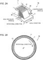
- FIG. 2A is a perspective view schematically showing the seal device 10 according to some embodiments.
- FIG. 2B is a diagram schematically showing a layout of thin plates 11 in the seal device 10.
- FIG. 3A is a diagram showing a static-pressure distribution in a gap between the thin plates 11 according to an embodiment.
- FIG. 3B is a cross-sectional view for describing the operation of a thin plate 11, taken in a direction perpendicular to the rotational axis O of the rotor 2.
- FIGs. 4A to 9 are each a configuration diagram of the seal device 10 according to each embodiment.
- FIG. 10 is a diagram for describing the interval of thin plates 11.
- the seal device 10 As shown in FIGs. 2A to 8D , the seal device 10 according to the present embodiment is disposed around the rotor 2 so as to separate the high-pressure space 8 and the low-pressure space 9, and configured to reduce the leakage amount of fluid (combustion gas) that leaks from the high-pressure space 8 to the low-pressure space 9.
- the seal device 10 has a thin-plate seal structure having a plurality of thin plates (leafs) 11 arranged in the circumferential direction of the rotor 2 in a multiple-layered fashion.
- the seal device 10 includes a plurality of thin plates 11 arranged along the outer peripheral surface of the rotor 2, a first side plate 20 disposed so as to face the high-pressure space 8, and a second side plate 22 disposed so as to face the low-pressure space 9.
- the plurality of thin plates 11 are disposed inside an annular space between the rotor 2 and the stator 7, and arranged in the circumferential direction of the rotor 2 in a multiple-layered fashion, separated from one another via a minute space.
- the plurality of thin plates 11 are disposed on the substantially same width-directional position with respect to the axial direction of the rotor 2.
- Each thin plate 11 is flexible, including a root portion 14 fixed to the stator 7 and a tip portion 12 being a free end disposed on the side of the rotor 2.
- Each thin plate 11 is disposed so as to be inclined to form an acute angle with the outer peripheral surface of the rotor 2 in the circumferential direction. That is, each thin plate 11 is disposed so as to be inclined to form an angle of more than zero degree with respect to the radial direction of the rotor 2. While the steam turbine 1 is stopped (the rotor 2 is stopped), the tip portion 12 of each thin plate 11 is in contact with the outer peripheral surface of the rotor 2.
- the first side plate 20 is an annular thin plate disposed so as to face the high-pressure space 8, and is formed so as to cover an outer-peripheral region (a region on the side of the root portion 14) of the first side surface 13a of each of the plurality of thin plates 11, the first side surface 13a being disposed on the side of the high-pressure space 8.
- the second side plate 22 is an annular thin plate disposed so as to face the low-pressure space 9, and is formed so as to cover an outer-peripheral region (a region on the side of the root portion 14) of the second side surface 13b of each of the plurality of thin plates 11, the side surface 13b being disposed on the side of the low-pressure space 9.
- the outer-peripheral side refers to the outside in the radial direction of the rotor 2.
- the first side surface 13a of each thin plate 11 is covered with the first side plate 20 over a region extending further to the inner side in the radial direction of the rotor 2 than a region of the second side face 13b that is covered with the second side plate 22.
- the distance between the outer peripheral surface of the rotor 2 and the inner peripheral edge 20a of the first side plate 20 (end portion on the side of the rotor 2) is smaller than the distance between the outer peripheral surface of the rotor 2 and the inner peripheral edge 22a of the second side plate 22 (end portion on the side of the rotor 2).
- FIG. 3A is a cross-sectional view of the seal device 10 along a plane passing through the gap between the thin plates 11.
- FIG. 3B is a cross-sectional view of the seal device 10 along a plane perpendicular to the width direction of the thin plates 11, that is a cross-sectional view taken in a direction perpendicular to the axial direction of the rotor 2.
- the thin plates 11 are inclined with respect to the outer peripheral surface of the rotor 2, and thus has a lower surface 11b facing the rotor 2 and an upper surface 11a disposed opposite to the lower surface 11b and facing the stator 7 (see FIG. 1 ). Furthermore, in the configuration example shown in FIG. 3A , in the width direction of the thin plate 11, the gap between the thin plate 11 and the second side plate 22 is greater than the gap between the thin plate 11 and the first side plate 20.
- a static-pressure distribution 30a is formed, in which the fluid pressure is highest at the end portion r1 of the tip portion 12 on the side of the high-pressure space 8 and becomes weaker gradually toward the corner portion r2 in the diagonally opposite position, on the upper surface 11a and the lower surface 11b of each thin plate 11.
- the fluid g flowing from the high-pressure space 8 toward the low-pressure space 9 forms a flow shown by the dotted line in FIG. 3A when passing through the gap between the thin plates 11.
- the fluid g flows into the gap between the thin plates 11 through the clearance between the outer peripheral surface of the rotor 2 and the inner peripheral edge 2 of the first side plate 20 from the high-pressure space 8, and forms an upward flow that flows from the end portion r1 of the tip portion 12 on the side of the high-pressure space 8 toward the corner portion r2 on the side of the root portion 14 on the side of the low-pressure space 9.
- the upward flow is formed radially from the side of the end portion r1 of the tip portion 12 on the side of the high-pressure space 8 in the gap between the thin plates 11.
- the fluid g forms a downward flow in the gap between the thin plates 11 and the second side plate 22, and flows into the low-pressure space 9 through the clearance between the outer peripheral surface of the rotor 2 and the inner peripheral edge 22a of the second side plate 22.
- the fluid-pressure distributions 30b, 30c applied in a perpendicular direction to the upper surface 11a and the lower surface 11b of each thin plate 11 has a triangular distribution shape that becomes larger toward the tip portion 12 and smaller toward the root portion 14.
- each thin plate 11 is disposed inclined so as to form an acute angle with the outer peripheral surface of the rotor 2, and thus the relative positions of the respective fluid-pressure distributions 30b, 30c of the upper surface 11a and the lower surface 11b are offset by the dimension s1. Accordingly, the upper surface 11a and the lower surface 11b have different fluid pressures at a point P on a line between the root portion 14 and the tip portion 12 of the thin plate 11.
- the fluid pressure (Fb) applied to the lower surface 11b is higher than the gas pressure (Fa) applied to the upper surface 11a, and thus the pressures act in a direction that the thin plate 11 deforms and levitates from the rotor 2. Meanwhile, the direction is opposite in the vicinity of the tip portion 12 of each thin plate 11, where the fluid pressure is applied only to the upper surface 11a.
- the thin plate 11 and the rotor 2 are mainly in a non-contact state, but a non-contact state and a contact state may exist mixed in time series.
- the above description features the mechanism to bring each thin plate 11 into a non-contact state with the rotor 2 by utilizing a pressure difference at pressurization from the high-pressure space 8. Besides this mechanism, levitation of each thin plate 11 is also caused in response to a dynamic-pressure effect from rotation of the rotor 2.
- each thin plate 11 is designed to have a predetermined rigidity that depends on the plate thickness in the axial direction of the rotor 2. Furthermore, each thin plate 11 is mounted to the stator 7 so as to form an acute angle with the outer peripheral surface of the rotor 2 with respect to the rotational direction of the rotor 2 as described above, so that the tip of each thin plate 11 is in contact with the rotor 2 at a predetermined pre-compression pressure while the rotor 2 is stopped, but each thin plate 11 and the rotor 2 are in a non-contact state when the rotor 2 rotates because the dynamic-pressure effect caused by rotation of the rotor 2 causes the tip of the thin plate 11 to levitate.
- the seal device 10 having the above configuration further includes the following configuration in order to suppress oscillation due to flutter of the thin plates 11 effectively while realizing the non-contact state of the thin plates 11 with the rotor 2 appropriately.
- each thin plate 11 is configured such that the width-direction of the thin plate 11 is parallel to the axial direction of the rotor 2 on the side of the root portion 14.
- the width direction between the first side surface 13a and the second side surface 13b of the thin plate 11 is parallel to the axial direction of the rotor 2.
- the thin plate 11 is less likely to be affected by the dynamic pressure on the side of the root portion 14, and thereby it is possible to suppress distortion of the side of the root portion 14 with respect to the axial direction of the rotor 2, which may impair levitation of the side of the tip portion 12.
- the end portion 12 of each thin plate 11 has an end on the side of the high-pressure space 8 that is disposed downstream of another end on the side of the low-pressure space 9 in the rotational direction of the rotor 2, in a cross-section along the width direction of the thin plate 11.
- the end portion 12b on the side of the high-pressure space 8 is disposed downstream of the end portion 12c on the side of the low-pressure space 9 in the rotational direction of the rotor 2.
- the tip portion 12 has an attack angle greater than 0° with respect to the flow of fluid that flows toward the low-pressure space 9 from the high-pressure space 8. Accordingly, a region of the tip portion 12 of the thin plate 11 on the side of the high-pressure space 8 more easily levitates from the outer peripheral surface of the rotor 2 in response to an influence of the dynamic pressure, and thus it is possible to realize the non-contact state between the rotor 2 and the thin plate 11 appropriately.
- the region of the tip portion 12 on the side of the high-pressure space 8 of the thin plate 11 is pushed upward from the outer peripheral surface of the rotor 2 due to an influence of the dynamic pressure, which makes it easier for the tip portion 12 to levitate. Furthermore, the region of the tip portion 12 on the side of the high-pressure space 8 deforms to distort with respect to the axial direction of the rotor 2 in response to an influence from the dynamic pressure, and thereby the thin plates 11 are more likely to contact each other at the side of the low-pressure space 9.
- the thin plates 11 support one another, and thereby it is possible to suppress oscillation of the thin plates 11 due to flutter.
- the tip portion 12 of the thin plate 11 levitates from the outer peripheral surface of the rotor 2 due to the static-pressure distribution as described above, and is in a non-contact state with respect to the outer peripheral surface of the rotor 2.
- the thin plate 11 having flexibility is slightly curved in the length direction from the root portion 14 to the tip portion 12.
- the levitation amount of the end portion 12b on the side of the high-pressure space 8 is greater than the levitation amount of the end portion 12c on the side of the low-pressure space 9 due to an influence of the dynamic pressure. That is, as in the cross-section of the tip portion 12 shown in FIGs. 4B to FIG.
- the end portion 12b on the side of the high-pressure space 8 is originally disposed downstream of the end portion 12c on the side of the low-pressure space 9 in the rotational direction of the rotor 2, and the end portion 12b on the side of the high-pressure space 8 levitates even further in response to an influence from the dynamic pressure, which causes the position of the end portion 12b on the side of the high-pressure space 8 to be offset further downstream in the rotational direction of the rotor 2.
- the thin plate 11 deforms to distort even further with respect to the width direction of the rotor 2.
- the plurality of thin plates 11 are arranged in the circumferential direction of the rotor 2, and thus the circumferential length R 2 passing through the root portions 14 of the thin plates 11 is greater than the circumferential length R 1 passing through the tip portions 12. Due to the circumferential-length difference between the circumferential length R 2 and the circumferential length R 1 , the distance ⁇ T 2 between the root portions 14 of adjacent thin plates 11 is greater than the distance ⁇ T 1 between the tip portions 12. That is, the gap between the tip portions 12 of adjacent thin plates 11 is narrower than the gap between the root portions 14. In particular, the gap between the tip portions 12 is narrower at the side of the low-pressure space closer to the outer peripheral surface of the rotor 2.
- the thin plates 11 are more likely to make contact with each other at the side of the low-pressure space 9.
- the thin plates 11 support one another when being in contact with one another, and thereby it is possible to suppress oscillation of the thin plates 11 due to flutter.
- the seal device 10 is configured such that the radial-directional position of the thin-plate tip surface 12a at the axial-directional position closest to the high-pressure space 8 is disposed on the inner side, in the radial direction, of the inner peripheral edge 20a of the first side plate 20.
- the space between the outer peripheral surface of the rotor 2 and the thin-plate tip surface 12a becomes excessively great, increasing the clearance between the outer peripheral surface of the rotor 2 and the thin-plate tip surface 12a at levitation of thin plate 11, which may decrease the shaft seal effect.
- the radial-directional position of the thin-plate tip surface 12a is on the inner side, in the radial direction, of the inner peripheral edge 20a of the first side plate 20, and thereby it is possible to form the space between the outer peripheral surface of the rotor 2 and the thin-plate tip surface 12a appropriately, and to suppress oscillation due to flutter while maintaining the shaft seal effect.
- each thin plate 11 has such a distribution that the side of the high-pressure space 8 is more away from the outer peripheral surface of the rotor 2 than the side of the low-pressure space 9, in the axial direction of the rotor 2. That is, each thin plate 11 is configured such that, of the thin-plate tip surface 12a, the distance between the end portion 12b on the side of the high-pressure space 8 and the outer peripheral surface of the rotor 2 is greater than the distance between the end portion 12c on the side of the low-pressure space 9 and the outer peripheral surface of the rotor 2.
- the tip portion 12 of the thin plate 11 is formed so that the distance between the thin-plate tip surface 12a and the outer peripheral surface of the rotor 2 decreases continuously or intermittently, or in stages, from the side of the high-pressure space 8 toward the side of the low-pressure space 9. Further, the tip portion 12 of the thin plate 11 is configured such that the radial-directional position of the thin-plate tip surface 12a at the axial-directional position closest to the high-pressure space 8 is disposed on the inner side, in the radial direction, of the inner peripheral edge 22a of the second side plate 22.
- the distance between the end portion 12b on the side of the high-pressure space 8 and the outer peripheral surface of the rotor 2 is smaller than the distance between the inner peripheral edge 22a of the second side plate 22 and the outer peripheral surface of the rotor 2.
- the seal device 10 may be configured such that the radial-directional position of the thin-plate tip surface 12a at the axial-directional position closest to the high-pressure space 8 is disposed on the inner side, in the radial direction, of the inner peripheral edge 20a of the first side plate 20.
- the space between the outer peripheral surface of the rotor 2 and the thin-plate tip surface 12a becomes excessively large, increasing the clearance between the outer peripheral surface of the rotor 2 and the thin-plate tip surface 12a at levitation of thin plate 11, which may decrease the shaft seal effect.
- the radial-directional position of the thin-plate tip surface 12a is on the inner side, in the radial direction, of the inner peripheral edge 20a of the first side plate 20, and thereby it is possible to form a space between the outer peripheral surface of the rotor 2 and the thin-plate tip surface 12a appropriately, and to suppress oscillation due to flutter while maintaining the shaft seal effect.
- the tip portion 12 of the thin plate 11 may be formed so that the distance between the thin-plate tip surface 12a and the outer peripheral surface of the rotor 2 decreases continuously or intermittently, or in stages, from the side of the high-pressure space 8 toward the side of the low-pressure space 9.
- FIGs. 4A to 9 features having the same configuration are associated with the same reference numeral, and features having different configurations are associated with different reference numerals.
- FIG. 4A is a cross-sectional view of a seal device according to an embodiment.
- FIG. 4B is a diagram of the seal device in FIG. 4A as seen in the direction of arrow A.
- FIG. 4C is a diagram of the seal device in FIG. 4A as seen in the direction of arrow B.
- FIG. 4D is a perspective view of the thin plate shown in FIG. 4A .
- each thin plate 11 further includes a distorted portion 12d having a curved shape disposed between the root portion 14 and the end portion 12 and connecting the root portion 14 and the tip portion 12.
- the distorted portion 12d is formed from the end portion 12b on the side of the high-pressure space 8 to the position 12e closer to the high-pressure space 8 than the end portion 12c on the side of the low-pressure space 9.
- FIG. 5A is a cross-sectional view of a seal device according to another embodiment.
- FIG. 5B is a diagram of the seal device in FIG. 5A as seen in the direction of arrow C.
- FIG. 5C is a diagram of the seal device in FIG. 5A as seen in the direction of arrow D.
- FIG. 5D is a perspective view of the thin plate shown in FIG. 5A .
- each thin plate 11 further includes a distorted portion 12d having a curved shape disposed between the root portion 14 and the end portion 12 and connecting the root portion 14 and the tip portion 12.
- the distorted portion 12d is formed over the entire region from the end portion 12b on the side of the high-pressure space 8 to the end portion 12c on the side of the low-pressure space 9.
- the position of the end portion 12c on the side of the low-pressure space 9 in the rotational direction is substantially the same as the position of the second side surface 13b on the side of the root portion 14. That is, the second side surface 13b is formed linearly from the root portion 14 to the tip portion 12.
- FIG. 6A is a cross-sectional view of a seal device according to another embodiment.
- FIG. 6B is a diagram of the seal device in FIG. 6A as seen in the direction of arrow E.
- FIG. 6C is a diagram of the seal device in FIG. 6A as seen in the direction of arrow F.
- FIG. 6D is a perspective view of the thin plate shown in FIG. 6A .
- each thin plate 11 further includes a bend portion 12f bended at a single flexure line 12g that extends inward in the radial direction toward the low-pressure space 9 from the high-pressure space 8.
- the flexure line 12g extends linearly from the first side surface 13a on the side of the high-pressure space 8 to the second side surface 13b on the side of the low-pressure space 9.
- configuration of the flexure line 12g is not limited to this.
- the flexure line 12g may extend linearly from the first side surface 13a on the side of the high-pressure space 8 to the tip surface 12a between the end portion 12b and the end portion 12c.
- two or more flexure lines 12g may be provided.
- FIG. 7A is a cross-sectional view of a seal device according to another embodiment.
- FIG. 7B is a diagram of the seal device in FIG. 7A as seen in the direction of arrow G.
- FIG. 7C is a diagram of the seal device in FIG. 7A as seen in the direction of arrow H.
- FIG. 7D is a perspective view of the thin plate shown in FIG. 7A .
- each thin plate 11 further includes a curved portion 12h curved downstream in the rotational direction at the side of the first side surface 13a, across a boundary along a curve start line 12i parallel to the first side surface 13a on the side of the high-pressure space 8.
- the curve start line 12i extends from the tip surface 12a closer to the tip portion 12 than the root portion 14. That is, there is a region on the side of the root portion 14 where the width direction of the thin plate 11 is parallel to the axial direction, and the curved portion 12h is formed closer to the tip portion 12 than this region.
- FIG. 8A is a cross-sectional view of a seal device according to another embodiment.
- FIG. 8B is a diagram of the seal device in FIG. 8A as seen in the direction of arrow I.
- FIG. 8C is a diagram of the seal device in FIG. 8A as seen in the direction of arrow J.
- FIG. 8D is a perspective view of the thin plate shown in FIG. 8A .
- FIG. 9 is a perspective view of the thin plate shown in FIGs. 8A to 8D .
- each thin plate 11 further includes a distorted portion 12j having a curved shape disposed between the root portion 14 and the tip portion 12 and connecting the root portion 14 and the tip portion 12.
- the distorted portion 12j is formed over the entire region from the end portion 12b on the side of the high-pressure space 8 to the end portion 12c on the side of the low-pressure space 9.
- the end portion 12c on the side of the low-pressure space 9 in the rotational direction is positioned downstream of the second side surface 13b on the side of the root portion 14 in the rotational direction. That is, the second side surface 13b is curved so that the end portion faces downstream on the side of the tip portion 12.
- each thin plate 11 is configured to satisfy a relationship ⁇ x 1 > ⁇ x 2 >0.
- the position offset amount ⁇ x 1 is the distance to the end portion 12b from the plane M along the side of the root portion 14 of the thin plate 11 (plane region), and the position offset amount ⁇ x w is the distance to the end portion 12c from the plane M.
- the tip portion 12 of the thin plate 11 is offset downstream in the rotational direction of the rotor 2 compared to the root portion 14 also on the side of the low-pressure space 9, and thus contact between the thin-plates 11 on the side of the low-pressure space 9 is even more likely to occur.
- the position of the end portion 12c on the side of the low-pressure space 9 in the rotational direction is downstream of the position of the second side surface 13b on the side of the root portion 14 in the rotational direction.
- the above described seal device 10 may further include the following configuration.
- the seal device 10 further includes a pair of retainers 26, 28 that hold the plurality of thin plates 11 at the side of the root portions 14. Further, the first side plate 20 and the second side plate 22 are supported by retainers 26, 28 while being nipped between the retainers 26, 28 and the both side surfaces 13a, 13b of the plurality of thin plates 11, respectively.
- the stator 7 includes an annular holding space 40 formed therein, for holding the retainers 26, 28, the first side plate 20 and the second side plate 22, and the plurality of thin plates 11.
- the holding space 40 is formed into a T shape in a cross section along the rotational axis O of the rotor 2.
- the holding space 40 includes a first space 41 formed on the inner peripheral side in the radial direction of the rotor 2 and communicating with the high-pressure space 8 and the low-pressure space 9, and a second space 42 formed on the outer peripheral side in the radial direction of the rotor 2 and communicating with the first space 41.
- Each of the thin plates 11 has a substantially T shape, the thickness being greater at the side of the root portion 14 than at the side of the tip portion 12. Cut-out portions 16a, 16b having a smaller thickness than the side of the tip portion 12 are disposed on the both side surfaces 13a, 13b between the root portion 14 and the tip portion 12.
- the pair of retainers 26, 28 have recessed portions 26a, 28a, respectively, and have a substantially U shape in a cross section including the rotational axis O of the rotor 2.
- the pair of retainers 26, 28 are accommodated in the second space 42 while the root portions 14 of the thin plates 11 are fit into the recessed portions 26a, 28a.
- the pair of retainers 26, 28 are configured to nip and support the root portions 14 of the plurality of thin plates 11 arranged in a multiple-layered fashion in the circumferential direction of the rotor 2 from the both side surfaces 13a, 13b.
- the first side plate 20 and the second side plate 22 have protruding portions 20b, 22b on the outer peripheral side in the radial direction of the rotor 2, respectively.
- the protruding portions 20b, 22b are configured to engage with the cut-out portions 16a, 16b of the thin plates 11. Further, the first side plate 20 and the second side plate 22 are supported by retainers 26, 28 while being nipped between the retainers 26, 28 and the both side surfaces 13a, 13b of the plurality of thin plates 11.
- the second space 42 may include a spacer nipped between the retainers 26, 28, for reducing backlash of the thin plates 11 with respect to the retainers 26, 28. Further, the second space 42 may be provided with a plurality of biasing members (e.g. plate springs) for supporting the plurality of thin plates 11 arranged in an annular shape in a levitation state so as to be coaxial with the rotational axis of the rotor 2.
- a plurality of biasing members e.g. plate springs
- the side of the root portion 14 of the thin plate 11 is less affected by the dynamic pressure, while the side of the tip portion 12 levitates easily from the outer peripheral surface of the rotor 2 in response to an influence of the dynamic pressure.
- the non-contact state between the rotor 2 and the thin plate 11 it is possible to realize the non-contact state between the rotor 2 and the thin plate 11 appropriately.
- the region of the tip portion 12 on the side of the high-pressure space 8 deforms to distort with respect to the axial direction of the rotor 2 in response to an influence of the dynamic pressure, and thereby the thin plates 11 are more likely to contact each other at the side of the low-pressure space 9. Accordingly, it is possible to suppress oscillation of the thin plates 11 due to flutter.
- the turbine according to the present embodiment is not limited to this, and may be another turbine such as the gas turbine 51 shown in FIG. 11 .
- the gas turbine 51 shown in FIG. 11 includes a compressor 53 for producing compressed air, a combustor 54 for producing combustion gas from the compressed air and fuel, and a turbine 55 configured to be rotary driven by combustion gas.
- a generator (not illustrated) is coupled to the turbine 55, so that rotational energy of the turbine 55 generates electric power.
- the gas turbine 51 of such type uses rotational energy of the turbine 55 as power source of the compressor 53 via the rotor 52 (corresponding to the rotor 2 of FIG. 1 ).
- the turbine 55 includes a plurality of rotor blades 56 disposed on the side of the rotor 52 (corresponding to the rotor blades 6 in FIG. 1 ), a stator (stationary portion) 57 including a casing 57a and a plurality of stationary vanes 57b (corresponding to the stationary vanes 7b in FIG. 1 ) disposed on the side of the casing 57a, and seal devices 50 disposed on the tips of the stationary vanes 57b.
- the above described seal device 10 can be used.
- the plurality of rotor blades 56 and the plurality of stationary vanes 57b are arranged alternately in the direction of the rotational axis O of the rotor 52 (hereinafter, referred to as the axial direction).
- the rotor 52 rotates as the combustion gas flowing along the axial direction passes through the rotor blades 56 and the stationary vanes 57b, and rotational energy imparted to the rotor 52 is extracted from the end of the shaft to be utilized for power generation or the like.
- an expression of relative or absolute arrangement such as “in a direction”, “along a direction”, “parallel”, “orthogonal”, “centered”, “concentric” and “coaxial” shall not be construed as indicating only the arrangement in a strict literal sense, but also includes a state where the arrangement is relatively displaced by a tolerance, or by an angle or a distance whereby it is possible to achieve the same function.
- an expression of an equal state such as “same” “equal” and “uniform” shall not be construed as indicating only the state in which the feature is strictly equal, but also includes a state in which there is a tolerance or a difference that can still achieve the same function.
- an expression of a shape such as a rectangular shape or a cylindrical shape shall not be construed as only the geometrically strict shape, but also includes a shape with unevenness or chamfered corners within the range in which the same effect can be achieved.
Landscapes
- Engineering & Computer Science (AREA)
- General Engineering & Computer Science (AREA)
- Mechanical Engineering (AREA)
- Chemical & Material Sciences (AREA)
- Combustion & Propulsion (AREA)
- Turbine Rotor Nozzle Sealing (AREA)
- Sealing Using Fluids, Sealing Without Contact, And Removal Of Oil (AREA)
- Sealing Devices (AREA)
Applications Claiming Priority (2)
| Application Number | Priority Date | Filing Date | Title |
|---|---|---|---|
| JP2015031944A JP6358976B2 (ja) | 2015-02-20 | 2015-02-20 | タービン用シール装置及びタービン、並びにシール装置用の薄板 |
| PCT/JP2016/053801 WO2016132966A1 (fr) | 2015-02-20 | 2016-02-09 | Dispositif d'étanchéité pour turbine, turbine, et plaque mince pour dispositif d'étanchéité |
Publications (3)
| Publication Number | Publication Date |
|---|---|
| EP3249172A1 true EP3249172A1 (fr) | 2017-11-29 |
| EP3249172A4 EP3249172A4 (fr) | 2018-03-21 |
| EP3249172B1 EP3249172B1 (fr) | 2020-01-08 |
Family
ID=56688920
Family Applications (1)
| Application Number | Title | Priority Date | Filing Date |
|---|---|---|---|
| EP16752352.1A Active EP3249172B1 (fr) | 2015-02-20 | 2016-02-09 | Dispositif d'étanchéité pour turbine, turbine, et plaque mince pour dispositif d'étanchéité |
Country Status (6)
| Country | Link |
|---|---|
| US (1) | US10662796B2 (fr) |
| EP (1) | EP3249172B1 (fr) |
| JP (1) | JP6358976B2 (fr) |
| KR (1) | KR101967084B1 (fr) |
| CN (1) | CN107250487B (fr) |
| WO (1) | WO2016132966A1 (fr) |
Families Citing this family (3)
| Publication number | Priority date | Publication date | Assignee | Title |
|---|---|---|---|---|
| JP6358976B2 (ja) * | 2015-02-20 | 2018-07-18 | 三菱日立パワーシステムズ株式会社 | タービン用シール装置及びタービン、並びにシール装置用の薄板 |
| KR20200102841A (ko) | 2019-02-22 | 2020-09-01 | 엘에스일렉트릭(주) | 아크 소호 장치 및 이를 포함하는 회로 차단기 |
| KR20210105744A (ko) | 2020-02-19 | 2021-08-27 | 엘에스일렉트릭(주) | 아크 챔버 및 이를 포함하는 배선용 차단기 |
Family Cites Families (37)
| Publication number | Priority date | Publication date | Assignee | Title |
|---|---|---|---|---|
| WO2000003164A1 (fr) | 1998-07-13 | 2000-01-20 | Mitsubishi Heavy Industries, Ltd. | Joint d'arbre et turbine utilisant ce joint |
| JP3616016B2 (ja) | 2000-04-28 | 2005-02-02 | 三菱重工業株式会社 | 軸シール機構及びガスタービン |
| JP3593082B2 (ja) * | 2001-10-09 | 2004-11-24 | 三菱重工業株式会社 | 軸シール機構及びタービン |
| JP4054608B2 (ja) * | 2002-05-23 | 2008-02-27 | イーグル工業株式会社 | 板ブラシシール |
| JP4009555B2 (ja) * | 2003-05-20 | 2007-11-14 | イーグル・エンジニアリング・エアロスペース株式会社 | 板ブラシシール装置 |
| CN100396885C (zh) * | 2003-05-21 | 2008-06-25 | 三菱重工业株式会社 | 轴密封机构、轴密封机构的组装结构和大型流体机械 |
| CN1324221C (zh) * | 2003-05-21 | 2007-07-04 | 三菱重工业株式会社 | 轴密封机构 |
| JP3872800B2 (ja) | 2003-05-21 | 2007-01-24 | 三菱重工業株式会社 | 軸シール機構、軸シール機構の組み付け構造、及び大型流体機械 |
| DE102004016173A1 (de) * | 2004-03-30 | 2005-10-20 | Alstom Technology Ltd Baden | Lamellendichtung, insbesondere für eine Gasturbine, sowie Verfahren zu deren Herstellung |
| JP3917993B2 (ja) * | 2004-08-10 | 2007-05-23 | 三菱重工業株式会社 | 軸シール機構及び軸シール機構をステータに取り付ける構造並びにこれらを備えたタービン。 |
| DE102004059858A1 (de) * | 2004-12-11 | 2006-06-29 | Alstom Technology Ltd | Lamellendichtung, insbesondere für eine Gasturbine |
| JP3970298B2 (ja) * | 2005-11-10 | 2007-09-05 | 三菱重工業株式会社 | 軸シール機構 |
| US7419164B2 (en) * | 2006-08-15 | 2008-09-02 | General Electric Company | Compliant plate seals for turbomachinery |
| FR2907356B1 (fr) * | 2006-10-20 | 2009-05-22 | Hef Soc Par Actions Simplifiee | Piece de frottement en milieu lubrifie et dont la surface est texturee. |
| GB0707224D0 (en) | 2007-04-14 | 2007-05-23 | Rolls Royce Plc | A seal arrangement |
| US7976026B2 (en) * | 2007-04-30 | 2011-07-12 | General Electric Company | Methods and apparatus to facilitate sealing in rotary machines |
| US7744092B2 (en) * | 2007-04-30 | 2010-06-29 | General Electric Company | Methods and apparatus to facilitate sealing in rotary machines |
| GB2461507B (en) | 2008-06-30 | 2010-09-08 | Rolls Royce Plc | A sealing device |
| GB2462255A (en) | 2008-07-28 | 2010-02-03 | Alstom Technology Ltd | A leaf seal for a rotary machine |
| US8262349B2 (en) * | 2008-12-22 | 2012-09-11 | General Electric Company | Adaptive compliant plate seal assemblies and methods |
| US8250756B2 (en) * | 2009-02-20 | 2012-08-28 | General Electric Company | Method of manufacture of compliant plate seals |
| DE102009015122A1 (de) * | 2009-03-31 | 2010-10-14 | Alstom Technology Ltd. | Lamellendichtung für eine Strömungsmaschine |
| EP2444699B1 (fr) * | 2009-06-16 | 2015-09-09 | Mitsubishi Hitachi Power Systems, Ltd. | Joint d'arbre et machine rotative pourvue de ce dernier |
| GB0922074D0 (en) * | 2009-12-18 | 2010-02-03 | Rolls Royce Plc | A leaf seal assembly |
| JP5473685B2 (ja) * | 2010-03-10 | 2014-04-16 | 三菱重工業株式会社 | 軸シール装置及び軸シール装置を備える回転機械 |
| JP5422481B2 (ja) * | 2010-05-10 | 2014-02-19 | 三菱重工業株式会社 | 軸シール装置の製造方法及び軸シール装置の生産治具、並びに、軸シール装置を備える回転機械 |
| US8474827B2 (en) * | 2010-06-11 | 2013-07-02 | Cmg Tech, Llc | Film riding pressure actuated leaf seal assembly |
| US8690158B2 (en) * | 2010-07-08 | 2014-04-08 | Siemens Energy, Inc. | Axially angled annular seals |
| US8382120B2 (en) * | 2010-08-31 | 2013-02-26 | General Electric Company | Method and apparatus for compliant plate seals |
| JP5631155B2 (ja) * | 2010-10-27 | 2014-11-26 | 三菱重工業株式会社 | 軸シール機構及びこれを備える回転機械 |
| JP5595259B2 (ja) | 2010-12-27 | 2014-09-24 | 三菱重工業株式会社 | 軸シール装置及びこれを備える回転機械 |
| JP5931450B2 (ja) * | 2012-01-13 | 2016-06-08 | 三菱重工業株式会社 | 軸シール装置及びこれを備える回転機械 |
| GB201202104D0 (en) * | 2012-02-08 | 2012-03-21 | Rolls Royce Plc | Leaf seal |
| GB201209705D0 (en) * | 2012-05-31 | 2012-07-18 | Rolls Royce Plc | Leaf seal |
| JP6012505B2 (ja) | 2013-02-22 | 2016-10-25 | 三菱重工業株式会社 | 軸シール装置及び回転機械 |
| GB201312766D0 (en) | 2013-07-19 | 2013-08-28 | Rolls Royce Plc | A leaf seal |
| JP6358976B2 (ja) * | 2015-02-20 | 2018-07-18 | 三菱日立パワーシステムズ株式会社 | タービン用シール装置及びタービン、並びにシール装置用の薄板 |
-
2015
- 2015-02-20 JP JP2015031944A patent/JP6358976B2/ja not_active Expired - Fee Related
-
2016
- 2016-02-09 WO PCT/JP2016/053801 patent/WO2016132966A1/fr active Application Filing
- 2016-02-09 KR KR1020177022656A patent/KR101967084B1/ko active IP Right Grant
- 2016-02-09 CN CN201680010746.8A patent/CN107250487B/zh not_active Expired - Fee Related
- 2016-02-09 US US15/550,891 patent/US10662796B2/en not_active Expired - Fee Related
- 2016-02-09 EP EP16752352.1A patent/EP3249172B1/fr active Active
Also Published As
| Publication number | Publication date |
|---|---|
| WO2016132966A1 (fr) | 2016-08-25 |
| KR20170103005A (ko) | 2017-09-12 |
| EP3249172A4 (fr) | 2018-03-21 |
| US10662796B2 (en) | 2020-05-26 |
| EP3249172B1 (fr) | 2020-01-08 |
| JP2016153625A (ja) | 2016-08-25 |
| CN107250487B (zh) | 2019-07-05 |
| US20180045065A1 (en) | 2018-02-15 |
| KR101967084B1 (ko) | 2019-04-08 |
| CN107250487A (zh) | 2017-10-13 |
| JP6358976B2 (ja) | 2018-07-18 |
Similar Documents
| Publication | Publication Date | Title |
|---|---|---|
| KR101832641B1 (ko) | 축 시일 장치 및 회전 기계 | |
| KR101721348B1 (ko) | 축 시일장치 및 회전기계 | |
| EP2444699A1 (fr) | Joint d'arbre et machine rotative pourvue de ce dernier | |
| US20100143102A1 (en) | Compliant plate seal with self-correcting behavior | |
| EP2532838A1 (fr) | Joint d'etancheité pour turbine | |
| EP3249172B1 (fr) | Dispositif d'étanchéité pour turbine, turbine, et plaque mince pour dispositif d'étanchéité | |
| EP2757275B1 (fr) | Retenue de palier de tourillon à feuille haute résistance | |
| US20180163557A1 (en) | Sealing device and rotary machine | |
| US20170067505A1 (en) | High strength foil journal bearing retainer | |
| EP3249267B1 (fr) | Dispositif d'étanchéité pour turbine, turbine, et plaque mince pour dispositif d'étanchéité | |
| US9593588B2 (en) | Shaft seal mechanism | |
| EP3220018B1 (fr) | Mécanisme d'étanchéité d'arbre | |
| EP3220019B1 (fr) | Mécanisme d'étanchéité d'arbre | |
| US20130001886A1 (en) | Twist proof flexures of seal assemblies |
Legal Events
| Date | Code | Title | Description |
|---|---|---|---|
| STAA | Information on the status of an ep patent application or granted ep patent |
Free format text: STATUS: THE INTERNATIONAL PUBLICATION HAS BEEN MADE |
|
| PUAI | Public reference made under article 153(3) epc to a published international application that has entered the european phase |
Free format text: ORIGINAL CODE: 0009012 |
|
| STAA | Information on the status of an ep patent application or granted ep patent |
Free format text: STATUS: REQUEST FOR EXAMINATION WAS MADE |
|
| 17P | Request for examination filed |
Effective date: 20170816 |
|
| AK | Designated contracting states |
Kind code of ref document: A1 Designated state(s): AL AT BE BG CH CY CZ DE DK EE ES FI FR GB GR HR HU IE IS IT LI LT LU LV MC MK MT NL NO PL PT RO RS SE SI SK SM TR |
|
| AX | Request for extension of the european patent |
Extension state: BA ME |
|
| A4 | Supplementary search report drawn up and despatched |
Effective date: 20180215 |
|
| RIC1 | Information provided on ipc code assigned before grant |
Ipc: F16J 15/44 20060101ALI20180210BHEP Ipc: F16J 15/22 20060101ALI20180210BHEP Ipc: F01D 11/12 20060101AFI20180210BHEP |
|
| DAV | Request for validation of the european patent (deleted) | ||
| DAX | Request for extension of the european patent (deleted) | ||
| REG | Reference to a national code |
Ref country code: DE Ref legal event code: R079 Ref document number: 602016027872 Country of ref document: DE Free format text: PREVIOUS MAIN CLASS: F01D0011120000 Ipc: F01D0011020000 |
|
| RIC1 | Information provided on ipc code assigned before grant |
Ipc: F16J 15/44 20060101ALI20190104BHEP Ipc: F01D 11/12 20060101ALI20190104BHEP Ipc: F01D 11/02 20060101AFI20190104BHEP Ipc: F16J 15/22 20060101ALI20190104BHEP Ipc: F02C 7/28 20060101ALI20190104BHEP Ipc: F16J 15/20 20060101ALI20190104BHEP |
|
| STAA | Information on the status of an ep patent application or granted ep patent |
Free format text: STATUS: EXAMINATION IS IN PROGRESS |
|
| 17Q | First examination report despatched |
Effective date: 20190222 |
|
| GRAP | Despatch of communication of intention to grant a patent |
Free format text: ORIGINAL CODE: EPIDOSNIGR1 |
|
| STAA | Information on the status of an ep patent application or granted ep patent |
Free format text: STATUS: GRANT OF PATENT IS INTENDED |
|
| INTG | Intention to grant announced |
Effective date: 20190917 |
|
| GRAS | Grant fee paid |
Free format text: ORIGINAL CODE: EPIDOSNIGR3 |
|
| GRAA | (expected) grant |
Free format text: ORIGINAL CODE: 0009210 |
|
| STAA | Information on the status of an ep patent application or granted ep patent |
Free format text: STATUS: THE PATENT HAS BEEN GRANTED |
|
| AK | Designated contracting states |
Kind code of ref document: B1 Designated state(s): AL AT BE BG CH CY CZ DE DK EE ES FI FR GB GR HR HU IE IS IT LI LT LU LV MC MK MT NL NO PL PT RO RS SE SI SK SM TR |
|
| REG | Reference to a national code |
Ref country code: GB Ref legal event code: FG4D |
|
| REG | Reference to a national code |
Ref country code: CH Ref legal event code: EP |
|
| REG | Reference to a national code |
Ref country code: DE Ref legal event code: R096 Ref document number: 602016027872 Country of ref document: DE |
|
| REG | Reference to a national code |
Ref country code: IE Ref legal event code: FG4D |
|
| REG | Reference to a national code |
Ref country code: AT Ref legal event code: REF Ref document number: 1222972 Country of ref document: AT Kind code of ref document: T Effective date: 20200215 |
|
| PGFP | Annual fee paid to national office [announced via postgrant information from national office to epo] |
Ref country code: GB Payment date: 20200227 Year of fee payment: 5 Ref country code: DE Payment date: 20200221 Year of fee payment: 5 |
|
| REG | Reference to a national code |
Ref country code: NL Ref legal event code: MP Effective date: 20200108 |
|
| REG | Reference to a national code |
Ref country code: LT Ref legal event code: MG4D |
|
| PG25 | Lapsed in a contracting state [announced via postgrant information from national office to epo] |
Ref country code: PT Free format text: LAPSE BECAUSE OF FAILURE TO SUBMIT A TRANSLATION OF THE DESCRIPTION OR TO PAY THE FEE WITHIN THE PRESCRIBED TIME-LIMIT Effective date: 20200531 Ref country code: RS Free format text: LAPSE BECAUSE OF FAILURE TO SUBMIT A TRANSLATION OF THE DESCRIPTION OR TO PAY THE FEE WITHIN THE PRESCRIBED TIME-LIMIT Effective date: 20200108 Ref country code: NO Free format text: LAPSE BECAUSE OF FAILURE TO SUBMIT A TRANSLATION OF THE DESCRIPTION OR TO PAY THE FEE WITHIN THE PRESCRIBED TIME-LIMIT Effective date: 20200408 Ref country code: FI Free format text: LAPSE BECAUSE OF FAILURE TO SUBMIT A TRANSLATION OF THE DESCRIPTION OR TO PAY THE FEE WITHIN THE PRESCRIBED TIME-LIMIT Effective date: 20200108 Ref country code: LT Free format text: LAPSE BECAUSE OF FAILURE TO SUBMIT A TRANSLATION OF THE DESCRIPTION OR TO PAY THE FEE WITHIN THE PRESCRIBED TIME-LIMIT Effective date: 20200108 Ref country code: NL Free format text: LAPSE BECAUSE OF FAILURE TO SUBMIT A TRANSLATION OF THE DESCRIPTION OR TO PAY THE FEE WITHIN THE PRESCRIBED TIME-LIMIT Effective date: 20200108 |
|
| PG25 | Lapsed in a contracting state [announced via postgrant information from national office to epo] |
Ref country code: IS Free format text: LAPSE BECAUSE OF FAILURE TO SUBMIT A TRANSLATION OF THE DESCRIPTION OR TO PAY THE FEE WITHIN THE PRESCRIBED TIME-LIMIT Effective date: 20200508 Ref country code: HR Free format text: LAPSE BECAUSE OF FAILURE TO SUBMIT A TRANSLATION OF THE DESCRIPTION OR TO PAY THE FEE WITHIN THE PRESCRIBED TIME-LIMIT Effective date: 20200108 Ref country code: LV Free format text: LAPSE BECAUSE OF FAILURE TO SUBMIT A TRANSLATION OF THE DESCRIPTION OR TO PAY THE FEE WITHIN THE PRESCRIBED TIME-LIMIT Effective date: 20200108 Ref country code: SE Free format text: LAPSE BECAUSE OF FAILURE TO SUBMIT A TRANSLATION OF THE DESCRIPTION OR TO PAY THE FEE WITHIN THE PRESCRIBED TIME-LIMIT Effective date: 20200108 Ref country code: GR Free format text: LAPSE BECAUSE OF FAILURE TO SUBMIT A TRANSLATION OF THE DESCRIPTION OR TO PAY THE FEE WITHIN THE PRESCRIBED TIME-LIMIT Effective date: 20200409 Ref country code: BG Free format text: LAPSE BECAUSE OF FAILURE TO SUBMIT A TRANSLATION OF THE DESCRIPTION OR TO PAY THE FEE WITHIN THE PRESCRIBED TIME-LIMIT Effective date: 20200408 |
|
| REG | Reference to a national code |
Ref country code: CH Ref legal event code: PL |
|
| REG | Reference to a national code |
Ref country code: DE Ref legal event code: R097 Ref document number: 602016027872 Country of ref document: DE |
|
| REG | Reference to a national code |
Ref country code: BE Ref legal event code: MM Effective date: 20200229 |
|
| PG25 | Lapsed in a contracting state [announced via postgrant information from national office to epo] |
Ref country code: SM Free format text: LAPSE BECAUSE OF FAILURE TO SUBMIT A TRANSLATION OF THE DESCRIPTION OR TO PAY THE FEE WITHIN THE PRESCRIBED TIME-LIMIT Effective date: 20200108 Ref country code: EE Free format text: LAPSE BECAUSE OF FAILURE TO SUBMIT A TRANSLATION OF THE DESCRIPTION OR TO PAY THE FEE WITHIN THE PRESCRIBED TIME-LIMIT Effective date: 20200108 Ref country code: SK Free format text: LAPSE BECAUSE OF FAILURE TO SUBMIT A TRANSLATION OF THE DESCRIPTION OR TO PAY THE FEE WITHIN THE PRESCRIBED TIME-LIMIT Effective date: 20200108 Ref country code: ES Free format text: LAPSE BECAUSE OF FAILURE TO SUBMIT A TRANSLATION OF THE DESCRIPTION OR TO PAY THE FEE WITHIN THE PRESCRIBED TIME-LIMIT Effective date: 20200108 Ref country code: LU Free format text: LAPSE BECAUSE OF NON-PAYMENT OF DUE FEES Effective date: 20200209 Ref country code: CZ Free format text: LAPSE BECAUSE OF FAILURE TO SUBMIT A TRANSLATION OF THE DESCRIPTION OR TO PAY THE FEE WITHIN THE PRESCRIBED TIME-LIMIT Effective date: 20200108 Ref country code: MC Free format text: LAPSE BECAUSE OF FAILURE TO SUBMIT A TRANSLATION OF THE DESCRIPTION OR TO PAY THE FEE WITHIN THE PRESCRIBED TIME-LIMIT Effective date: 20200108 Ref country code: RO Free format text: LAPSE BECAUSE OF FAILURE TO SUBMIT A TRANSLATION OF THE DESCRIPTION OR TO PAY THE FEE WITHIN THE PRESCRIBED TIME-LIMIT Effective date: 20200108 Ref country code: DK Free format text: LAPSE BECAUSE OF FAILURE TO SUBMIT A TRANSLATION OF THE DESCRIPTION OR TO PAY THE FEE WITHIN THE PRESCRIBED TIME-LIMIT Effective date: 20200108 |
|
| PLBE | No opposition filed within time limit |
Free format text: ORIGINAL CODE: 0009261 |
|
| STAA | Information on the status of an ep patent application or granted ep patent |
Free format text: STATUS: NO OPPOSITION FILED WITHIN TIME LIMIT |
|
| REG | Reference to a national code |
Ref country code: AT Ref legal event code: MK05 Ref document number: 1222972 Country of ref document: AT Kind code of ref document: T Effective date: 20200108 |
|
| PG25 | Lapsed in a contracting state [announced via postgrant information from national office to epo] |
Ref country code: CH Free format text: LAPSE BECAUSE OF NON-PAYMENT OF DUE FEES Effective date: 20200229 Ref country code: LI Free format text: LAPSE BECAUSE OF NON-PAYMENT OF DUE FEES Effective date: 20200229 |
|
| REG | Reference to a national code |
Ref country code: DE Ref legal event code: R082 Ref document number: 602016027872 Country of ref document: DE Representative=s name: HOFFMANN - EITLE PATENT- UND RECHTSANWAELTE PA, DE Ref country code: DE Ref legal event code: R081 Ref document number: 602016027872 Country of ref document: DE Owner name: MITSUBISHI POWER, LTD., JP Free format text: FORMER OWNER: MITSUBISHI HITACHI POWER SYSTEMS, LTD., YOKOHAMA-SHI, KANAGAWA, JP |
|
| 26N | No opposition filed |
Effective date: 20201009 |
|
| PG25 | Lapsed in a contracting state [announced via postgrant information from national office to epo] |
Ref country code: FR Free format text: LAPSE BECAUSE OF NON-PAYMENT OF DUE FEES Effective date: 20200308 Ref country code: IE Free format text: LAPSE BECAUSE OF NON-PAYMENT OF DUE FEES Effective date: 20200209 Ref country code: IT Free format text: LAPSE BECAUSE OF FAILURE TO SUBMIT A TRANSLATION OF THE DESCRIPTION OR TO PAY THE FEE WITHIN THE PRESCRIBED TIME-LIMIT Effective date: 20200108 Ref country code: AT Free format text: LAPSE BECAUSE OF FAILURE TO SUBMIT A TRANSLATION OF THE DESCRIPTION OR TO PAY THE FEE WITHIN THE PRESCRIBED TIME-LIMIT Effective date: 20200108 |
|
| PG25 | Lapsed in a contracting state [announced via postgrant information from national office to epo] |
Ref country code: SI Free format text: LAPSE BECAUSE OF FAILURE TO SUBMIT A TRANSLATION OF THE DESCRIPTION OR TO PAY THE FEE WITHIN THE PRESCRIBED TIME-LIMIT Effective date: 20200108 Ref country code: PL Free format text: LAPSE BECAUSE OF FAILURE TO SUBMIT A TRANSLATION OF THE DESCRIPTION OR TO PAY THE FEE WITHIN THE PRESCRIBED TIME-LIMIT Effective date: 20200108 Ref country code: BE Free format text: LAPSE BECAUSE OF NON-PAYMENT OF DUE FEES Effective date: 20200229 |
|
| REG | Reference to a national code |
Ref country code: DE Ref legal event code: R119 Ref document number: 602016027872 Country of ref document: DE |
|
| GBPC | Gb: european patent ceased through non-payment of renewal fee |
Effective date: 20210209 |
|
| PG25 | Lapsed in a contracting state [announced via postgrant information from national office to epo] |
Ref country code: GB Free format text: LAPSE BECAUSE OF NON-PAYMENT OF DUE FEES Effective date: 20210209 Ref country code: DE Free format text: LAPSE BECAUSE OF NON-PAYMENT OF DUE FEES Effective date: 20210901 |
|
| PG25 | Lapsed in a contracting state [announced via postgrant information from national office to epo] |
Ref country code: TR Free format text: LAPSE BECAUSE OF FAILURE TO SUBMIT A TRANSLATION OF THE DESCRIPTION OR TO PAY THE FEE WITHIN THE PRESCRIBED TIME-LIMIT Effective date: 20200108 Ref country code: MT Free format text: LAPSE BECAUSE OF FAILURE TO SUBMIT A TRANSLATION OF THE DESCRIPTION OR TO PAY THE FEE WITHIN THE PRESCRIBED TIME-LIMIT Effective date: 20200108 Ref country code: CY Free format text: LAPSE BECAUSE OF FAILURE TO SUBMIT A TRANSLATION OF THE DESCRIPTION OR TO PAY THE FEE WITHIN THE PRESCRIBED TIME-LIMIT Effective date: 20200108 |
|
| PG25 | Lapsed in a contracting state [announced via postgrant information from national office to epo] |
Ref country code: MK Free format text: LAPSE BECAUSE OF FAILURE TO SUBMIT A TRANSLATION OF THE DESCRIPTION OR TO PAY THE FEE WITHIN THE PRESCRIBED TIME-LIMIT Effective date: 20200108 Ref country code: AL Free format text: LAPSE BECAUSE OF FAILURE TO SUBMIT A TRANSLATION OF THE DESCRIPTION OR TO PAY THE FEE WITHIN THE PRESCRIBED TIME-LIMIT Effective date: 20200108 |