EP3248892A1 - Push-in mechanism and box packing device provided with same - Google Patents
Push-in mechanism and box packing device provided with same Download PDFInfo
- Publication number
- EP3248892A1 EP3248892A1 EP15878867.9A EP15878867A EP3248892A1 EP 3248892 A1 EP3248892 A1 EP 3248892A1 EP 15878867 A EP15878867 A EP 15878867A EP 3248892 A1 EP3248892 A1 EP 3248892A1
- Authority
- EP
- European Patent Office
- Prior art keywords
- push
- plate
- box
- articles
- distance
- Prior art date
- Legal status (The legal status is an assumption and is not a legal conclusion. Google has not performed a legal analysis and makes no representation as to the accuracy of the status listed.)
- Granted
Links
Images








Classifications
-
- B—PERFORMING OPERATIONS; TRANSPORTING
- B65—CONVEYING; PACKING; STORING; HANDLING THIN OR FILAMENTARY MATERIAL
- B65B—MACHINES, APPARATUS OR DEVICES FOR, OR METHODS OF, PACKAGING ARTICLES OR MATERIALS; UNPACKING
- B65B35/00—Supplying, feeding, arranging or orientating articles to be packaged
- B65B35/30—Arranging and feeding articles in groups
- B65B35/40—Arranging and feeding articles in groups by reciprocating or oscillatory pushers
- B65B35/405—Arranging and feeding articles in groups by reciprocating or oscillatory pushers linked to endless conveyors
-
- B—PERFORMING OPERATIONS; TRANSPORTING
- B65—CONVEYING; PACKING; STORING; HANDLING THIN OR FILAMENTARY MATERIAL
- B65B—MACHINES, APPARATUS OR DEVICES FOR, OR METHODS OF, PACKAGING ARTICLES OR MATERIALS; UNPACKING
- B65B5/00—Packaging individual articles in containers or receptacles, e.g. bags, sacks, boxes, cartons, cans, jars
- B65B5/06—Packaging groups of articles, the groups being treated as single articles
-
- B—PERFORMING OPERATIONS; TRANSPORTING
- B65—CONVEYING; PACKING; STORING; HANDLING THIN OR FILAMENTARY MATERIAL
- B65B—MACHINES, APPARATUS OR DEVICES FOR, OR METHODS OF, PACKAGING ARTICLES OR MATERIALS; UNPACKING
- B65B5/00—Packaging individual articles in containers or receptacles, e.g. bags, sacks, boxes, cartons, cans, jars
- B65B5/10—Filling containers or receptacles progressively or in stages by introducing successive articles, or layers of articles
- B65B5/106—Filling containers or receptacles progressively or in stages by introducing successive articles, or layers of articles by pushers
Definitions
- the present invention relates to a push-in mechanism and a box packing device provided with the same.
- Patent Document No. 1 Japanese Laid-Open Patent Publication No. 2010-155648 discloses one example of such a box packing device.
- Most box packing devices are functionally divided into a feed mechanism, an accumulating mechanism, and a push-in mechanism.
- the feed mechanism feeds wrapped articles one at a time.
- the accumulating mechanism accumulates a predetermined number of wrapped articles among the wrapped articles supplied by the feed mechanism.
- the push-in mechanism pushes the group of accumulated wrapped articles into a cardboard box. The push-in action is repeated a predetermined number of times for one cardboard box.
- An object of the present invention is to increase the speed of the push-in action and improve the efficiency of the production line.
- a push-in mechanism pushes articles into a box that is opened sideways.
- the push-in mechanism is provided with a box standby part, an article placement part, a push-in plate, a horizontal movement mechanism, and a lifting/lowering mechanism.
- the box standby part is configured to cause the box to wait.
- the article placement part has a placement surface on which the articles are temporarily placed.
- the push-in plate is installed in a standing state so as to have a pressing surface configured to push the articles toward the box.
- the horizontal movement mechanism is configured to reciprocate the push-in plate horizontally over the placement surface such that the push-in plate moves toward the box or moves away from the box.
- the lifting/lowering mechanism is configured to move the push-in plate so as to change a separation distance in the height direction between a lower edge of the pressing surface and the placement surface.
- the height of the lower edge of the pressing surface can be changed. Therefore, after the push-in action of the push-in plate pushing the article into the box is finished, hindering of the movement of the next article to be pushed into the box can be suppressed by increasing the height of the lower edge of the pressing surface.
- the push-in mechanism according to a second aspect of the present invention is related to the push-in mechanism according to the first aspect, wherein the push-in plate has a first plate and a second plate.
- the first plate is installed in a standing state.
- the second plate is installed in a standing state closer to the placement surface than the first plate.
- the second plate has the pressing surface described in the first aspect.
- the lifting/lowering mechanism is configured to move the second plate in the height direction to change the separation distance.
- the dimension in the height direction of the push-in plate is extended and shrunk by the movement of the second plate. Therefore, the push-in mechanism conforms to articles of varying sizes.
- the push-in mechanism according to a third aspect of the present invention is related to the push-in mechanism according to the first aspect or the second aspect, wherein the lifting/lowering mechanism is configured to set the separation distance to a first distance when the horizontal movement mechanism moves the push-in plate toward the box.
- the lifting/lowering mechanism is configured to set the separation distance to a second distance when the horizontal movement mechanism moves the push-in plate away from the box. The second distance is greater than the first distance.
- the height of the lower edge of the pressing surface increases during the return action of the push-in plate. Therefore, the next article to be pushed into the box can be moved during the return action of the push-in plate and, consequently, the speed of the push-in action can be increased.
- the push-in mechanism according to a fourth aspect of the present invention is related to the push-in mechanism according to the first aspect or the second aspect, wherein the lifting/lowering mechanism is configured to set the separation distance to a first distance when the horizontal movement mechanism moves the push-in plate toward the box.
- the lifting/lowering mechanism is configured to set the separation distance to a second distance when the horizontal movement mechanism moves the push-in plate away from the box.
- the second distance is greater than the first distance when the size of the article is smaller than a predetermined size.
- the second distance is equal to the first distance when the size of the article is greater than the predetermined size.
- an article having a greater height can be packed into the box in a stable manner due to the second plate as well as the first plate being involved in the pushing action.
- the push-in mechanism according to a fifth aspect of the present invention is related to the push-in mechanism described in any one of the first aspect to fourth aspect, wherein the push-in plate is configured to extend and retract in the width direction.
- the width direction is perpendicular to both of the reciprocating direction and the height direction of the push-in plates.
- the width of the push-in plate can be increased when handling a large product wrapped in a bag, for example. Therefore, the push-in action of an article that is larger than a predetermined size can be carried out in a stable manner.
- a box packing device comprises a feed mechanism, an accumulating mechanism, and the push-in mechanism.
- the feed mechanism is configured to feed the articles in order one at a time.
- the accumulating mechanism is configured to accumulate a predetermined number of the articles.
- the push-in mechanism is configured to push a predetermined number of the articles into a box.
- the push-in mechanism is according to any one of the first to fifth aspects.
- the box packing device is provided with a push-in mechanism having a fast processing speed. Therefore, the processing speed of the box packing device can be improved.
- the box packing device is related to the box packing device according to the sixth aspect, wherein the accumulating mechanism has a first conveyor belt, a second conveyor belt, and a third conveyor belt.
- the first conveyor belt is configured to receive articles from the feed mechanism.
- the first conveyor belt is disposed in an inclined manner.
- the second conveyor belt is configured to form an article group including the predetermined number of the articles.
- the third conveyor belt is configured to receive the article group from the second conveyor belt and temporarily hold the article group.
- the article placement mechanism has a placement conveyor belt.
- the placement conveyor belt is configured to receive the article group from the third conveyor belt and move the article group to the placement surface.
- the third conveyor belt of the accumulating mechanism functions as a buffer. Therefore, the accumulating mechanism can be prevented from becoming a bottleneck in the production line.
- the push-in mechanism as in the present invention hindering of the movement of the articles can be suppressed.
- the processing speed of the box packing device in which the push-in mechanism is mounted is faster.
- FIG. 1 illustrates a configuration of a box packing device 500A according to a first embodiment of the present invention.
- the box packing device 500A receives articles WP wrapped in bags from a wrapping device one at a time and packs a predetermined number of the articles WP into a box.
- the box packing device 500A is provided with a feed mechanism 100, an accumulating mechanism 200A, and a push-in mechanism 300.
- the feed mechanism 100 receives the articles WP wrapped in bags one at a time from an unillustrated wrapping device installed in the previous stage of the box packing device 500A, feeds the articles WP in a feeding direction F1, and passes the articles WP on to the accumulating mechanism 200A.
- the feed mechanism 100 has a feed conveyor belt 110 and a discharge conveyor belt 120.
- the discharge conveyor belt 120 is disposed in an inclined manner.
- the accumulating mechanism 200A accumulates a predetermined number of the articles WP.
- the accumulating mechanism 200A has a first conveyor belt 210 and a second conveyor belt 220.
- the first conveyor belt 210 is inclined with respect to the horizontal direction and forms a sloped surface.
- the first conveyor belt 210 constantly operates.
- the second conveyor belt 220 is stopped or operates at a low speed until the predetermined number of the articles WP are accumulated. As a result, a plurality of the articles WP fed sequentially from the feed mechanism 100 are accumulated on the second conveyor belt 220 in a partially overlapped manner.
- the second conveyor belt 220 When the predetermined number of the articles WP are accumulated, the second conveyor belt 220 operates at a high speed and passes the group of the articles WP on to the push-in mechanism 300.
- the push-in mechanism 300 receives the predetermined number of articles WP accumulated by the accumulating mechanism 200A, aligns the articles WP and packs the articles WP into a box.
- FIG. 2 illustrates a configuration of the push-in mechanism 300.
- the push-in mechanism 300 has an article placement part 310, a stopper 320, a support plate 330, a push-in plate 340, a box standby part 350, a horizontal movement mechanism 360, and a lifting/lowering mechanism 370.
- the article placement part 310 is for placing one group of the articles WP to be boxed.
- the article placement part 310 includes a conveyor belt and is able to feed the articles WP in a feeding direction F2.
- the upper surface of the article placement part 310 constitutes a placement surface SS regardless of the rotation state of the conveyor belt, and the article placement part 310 feeds one group of the articles WP received from the accumulating mechanism 200A to the placement surface SS.
- the stopper 320 is a plate for blocking the movement of the front end of a group of the articles WP.
- the support plate 330 is a plate for supporting the rear end of a group of the articles WP after the group of the articles WP is received by the push-in mechanism 300.
- the stopper 320 and the support plate 330 are able to move appropriately for capturing and aligning a group of the articles WP.
- the push-in plate 340 is able to move or reciprocate in a reciprocating direction P due to the horizontal movement mechanism 360.
- the push-in plate 340 has a first plate 341 and a second plate 342.
- the first plate 341 is fixed to the horizontal movement mechanism 360.
- the second plate 342 is able to move relative to the first plate in a height direction V.
- the push-in plate 340 has a pressing surface SP, which is able to push a group of the articles WP. At least the second plate 342 has the pressing surface SP.
- the push-in plate 340 packs a group of the articles WP into a box B by moving closer to the box B.
- the box standby part 350 has an unillustrated lifting/lowering mechanism so as to allow for lifting and lowering.
- the lifting/lowering mechanism moves the box B into which a group of the articles WP have been packed to a subsequent process and brings a new empty box B to the place where packing will be performed to it.
- the horizontal movement mechanism 360 moves the push-in plate 340 in the reciprocating direction P.
- the horizontal movement mechanism 360 has a beam 361 and a fixing member 362.
- the first plate 341 of the push-in plate 340 is fixed to the fixing member 362.
- the fixing member 362 is moved in the reciprocating direction P along the beam 361 by a drive mechanism which is not illustrated.
- the lifting/lowering mechanism 370 lifts and lowers the second plate 342 by moving the second plate 342 relative to the first plate 341 in the height direction V.
- the lifting/lowering mechanism 370 has a roller 371 and a belt 372.
- the roller 371 is fixed to the fixing member 362 in a rotatable manner and is rotated by a motor which is not illustrated.
- the belt 372 has one end fixed to the roller 371 and the other end fixed to the second plate. Due to the force of the motor, the roller 371 winds the belt 372 up or returns the belt 372 whereby the second plate 342 is lifted or lowered.
- FIG. 4A to 4C illustrate push-in actions executed by the push-in mechanism 300.
- FIG. 4A illustrates the first step of the push-in action.
- a group of the articles WP that has come from the accumulating mechanism 200A ( FIG. 1 ) is placed on the placement surface SS of the article placement part 310.
- the second plate 342 is lowered.
- the height of the placement surface SS and the height of the lower edge of the pressing surface SP are separated from each other by a first distance d1.
- FIG. 4B illustrates the second step of the push-in action.
- the push-in plate 340 moves toward the box B and consequently the pressing surface SP pushes the group of the articles WP toward the box B.
- the group of the articles WP is packed into the box B.
- the separation distance between the height of the placement surface SS and the height of the lower edge of the pressing surface SP is maintained at the first distance d1.
- FIG. 4C illustrates the third step of the push-in action.
- the push-in plate 340 returns to the location of the first step.
- the second plate 342 is lifted upward.
- the separation distance between the height of the placement surface SS and the height of the lower edge of the pressing surface SP becomes a second distance d2 which is greater than the first distance d1.
- the push-in action returns to the first step.
- the lifting/lowering mechanism 370 in the push-in mechanism 300 is able to move the push-in plate 340 so that the distance separating the lower edge of the pressing surface SP and the placement surface SS in the height direction changes. Therefore, after the push-in action of the push-in plate 340 pushing the articles into the box B is finished, hindering of the movement of the next articles WP to be pushed into the box can be suppressed by increasing the height of the lower edge of the pressing surface SP.
- the first plate 341 is installed in a standing state and the second plate 342 is also installed in a standing state closer to the placement surface SS than the first plate 341.
- the pressing surface SP is present at least on the second plate 342.
- the second plate 342 is moved in the height direction V by the lifting/lowering mechanism 370. Therefore, because the dimension in the height direction V of the push-in plate 340 can be extended and shrunk, the push-in mechanism 300 is able to handle articles WP of various sizes.
- the lifting/lowering mechanism 370 sets the separation distance to the first distance d1 when the horizontal movement mechanism 360 moves the push-in plate 340 toward the box B.
- the lifting/lowering mechanism 370 sets the separation distance to the second distance d2, which is greater than the first distance d1, when the horizontal movement mechanism 360 moves the push-in plate 340 away from the box B. Therefore, the movement of the next articles WP to be pushed into the same box B or a different new box B can be performed during the return action of the push-in plate 340, and consequently the speed of the push-in action can be improved.
- the box packing device 500A is provided with the push-in mechanism 300 having a fast processing speed. Therefore, the processing speed of the box packing device 500A is improved.
- the push-in mechanism 300 mounted in the box packing device 500A according to a first modified example 1A of the first embodiment changes the action of the lifting/lowering mechanism 370 according to the size of the article WP.
- the box packing device 500A according to the first modified example 1A is further provided with a detection means, which is not illustrated, for detecting the size of the article WP, specifically, the height h of the article WP.
- the box packing device 500A determines, on the basis of a signal from the detection means, whether the height h of the article WP is greater than the second distance d2 explained in FIG. 4C .
- the push-in mechanism 300 according to the modified example 1A performs the push-in action including the steps illustrated in FIG. 4A to 4C in the same way as the push-in mechanism 300 according to the first embodiment.
- the push-in mechanism 300 performs a push-in action including a first step in FIG. 5A and then a second step in FIG. 5B .
- the second plate 342 is lowered and the height of the placement surface SS and the height of the lower edge of the pressing surface SP are separated from each other by the first distance d1.
- the push-in plate 340 approaches the box B and consequently the pressing surface SP pushes the group of the articles WP toward the box B.
- the first plate 341 contributes to the action of pushing the article WP.
- the height of the placement surface SS and the height of the lower edge of the pressing surface SP are still separated from each other by the first distance d1.
- the push-in plate 340 is returned to the disposition in FIG. 5A . Thereafter, the next group of the articles WP to be boxed arrives at the placement surface SS, and then the first step is executed again.
- the first plate 341 as well as the second plate 342 contribute to the action of pushing the article WP and therefore the article WP having the large height h can be packed into the box B in a stable manner.
- the push-in mechanism 300 mounted in the box packing device 500A according to a second modified example 1B of the first embodiment extends and retracts the width of the push-in plate 340 according to the size of the article WP.
- FIG. 6 illustrates a configuration of the push-in plate 340 according to the second modified example 1B.
- the push-in plate 340 has a first plate 341 and a second plate 342.
- the first plate 341 has a first plate extension part 341a that allows for extension and retraction in the width direction W.
- the second plate 342 similarly has a second plate extension part 342a that allows for extension and retraction in the width direction W.
- the width direction W is a direction perpendicular to both the reciprocating direction P and the height direction V of the push-in plate 340.
- the extension and retraction is carried out automatically by an extending mechanism which is not illustrated.
- the box packing device 500A according to the second modified example 1B is further provided with a detecting means, which is not illustrated, for detecting the size of the article WP, specifically, the dimension in the feeding direction F2 ( FIG. 2 ), namely, the dimension in the width direction W of the article WP.
- the width of the push-in plate 340 can be increased due to the extension of the first plate extension part 341a and the second plate extension part 342a when handling the article WP having a dimension equal to or greater than a predetermined value. Therefore, the push-in action of a large article WP can be performed in a stable manner.
- the push-in mechanism 300 mounted in the box packing device 500A according to a third modified example 1C of the first embodiment also extends and retracts the width of the push-in plate 340 according to the size of the article WP.
- FIG. 7A illustrates the push-in mechanism 300 according to the third modified example 1C.
- the push-in plate 340 of the push-in mechanism 300 has a third plate 343 and a fourth plate 344 in addition to the first plate 341 and the second plate 342, and, as a result, differs from the first embodiment and the first modified example 1A and the second modified example 1B thereof.
- At least the second plate 342 among the first plate 341, the second plate 342, the third plate 343, and the fourth plate 344 has the pressing surface SP.
- FIGS. 7B to 7E illustrate a configuration of the push-in plate 340 according to the third modified example 1C.
- the push-in plate 340 has a three-layer structure.
- the first layer includes the second plate 342.
- the second layer includes the first plate 341 and the third plate 343.
- the third layer includes the fourth plate 344.
- the first plate 341 is fixed to the horizontal movement mechanism 360, which is not illustrated in FIG. 7B , in the same way the explained above with regard to the first embodiment, and the first modified example 1A and the second modified example 1B thereof.
- FIG. 7C illustrates the push-in plate 340 while the second plate 342 is lifted upward so as to approach the first plate 341. This form corresponds to the third step of the push-in action explained with reference to FIG. 4C .
- FIG. 7D illustrates the push-in plate 340 while the second plate 342 is lowered so as to approach the placement surface SS ( FIG. 7A ).
- This form corresponds to the first step and the second step of the push-in action explained with reference to FIGS. 4A and 4B .
- the third plate 343 is also lowered with the second plate 342.
- FIG. 7E illustrates the push-in plate 340 that has been extended further in the width direction W.
- the third plate 343 and the fourth plate 344 are moved relative to the first plate 341 and the second plate 342.
- the first plate 341 and the third plate 343 that similarly configure the second layer are present on the same plane.
- the push-in mechanism 300 mounted in the box packing device 500A according to the third modified example 1C of the first embodiment does not have the lifting/lowering mechanism 370 of the first embodiment, and in place thereof, has an extension mechanism, which is not illustrated, for changing the form of the push-in plate 340 as illustrated in FIGS. 7C to 7E .
- the first plate 341, the second plate 342, the third plate 343, and the fourth plate 344 are configured by thin plates having a thickness, for example, of 1.5 mm or less. Therefore, the step between the second plate 342 and the fourth plate 344 is a small dimension of 3.0 mm or less in the extended push-in plate 340 illustrated in FIG. 7E .
- the push-in plate 340 when the push-in plate 340 pushes the article WP toward the box B, the push-in plate 340 is able to push the article WP with a uniform force because the step between the first plate 341, the second plate 342, the third plate 343, and the fourth plate 344 is small. Therefore, the push-in action can be performed in a stable manner.
- FIG. 8 illustrates a configuration of a box packing device 500B according to a second embodiment of the present invention.
- An accumulating mechanism 200B having a different configuration is mounted in the box packing device 500B of the second embodiment in place of the accumulating mechanism 200A mounted in the box packing device 500A according to the first embodiment or the modified examples thereof.
- the box packing device 500B of the second embodiment is the same as the box packing device 500A according to the first embodiment in the other aspects.
- the accumulating mechanism 200B differs from the accumulating mechanism 200A according to the first embodiment in that the accumulating mechanism 200B has a third conveyor belt 230 in addition to the first conveyor belt 210 and the second conveyor belt 220.
- the first conveyor belt 210 is inclined with respect to the horizontal direction and forms a sloped surface.
- the first conveyor belt 210 constantly operates.
- the second conveyor belt 220 is stopped or operates at a low speed until the predetermined number of the articles WP are accumulated. As a result, a plurality of the articles WP fed sequentially from the feed mechanism 100 are accumulated on the second conveyor belt 220 in a partially overlapping manner.
- the second conveyor belt 220 When the predetermined number of the articles WP are accumulated, the second conveyor belt 220 operates at a high speed and passes the group of the articles WP on to the third conveyor belt 230.
- the third conveyor belt 230 operates when predetermined conditions, such as the state of the subsequent push-in mechanism 300 and the like, are satisfied, and passes the group of the articles WP on to the push-in mechanism 300.
- the third conveyor belt 230 functions as a buffer.
- the third conveyor belt 230 is not able to pass the group of the articles WP on to the push-in mechanism 300 and therefore holds the group of the articles WP.
- the accumulating mechanism 200B is able to execute the accumulation action by using the first conveyor belt 210 and the second conveyor belt 220. Therefore, the utilization rate of the accumulating mechanism 200B is improved and the accumulating mechanism 200B can avoid becoming a bottleneck in the production line.
- the configurations of the push-in mechanism 300 according to the first modified example 1A, the second modified example 1B, and the third modified example 1C of the first embodiment may be integrated with the box packing device 500B according to the second embodiment.
- Patent Document 1 Japanese Patent Laid-open No. 2010-155648
Landscapes
- Engineering & Computer Science (AREA)
- Mechanical Engineering (AREA)
- Container Filling Or Packaging Operations (AREA)
Abstract
Description
- The present invention relates to a push-in mechanism and a box packing device provided with the same.
- Box packing devices are often used for packing a plurality of wrapped articles automatically in cardboard boxes for the purpose of shipment in factories that produce products wrapped in film bags. Patent Document No. 1 (Japanese Laid-Open Patent Publication No.
2010-155648 - Most box packing devices are functionally divided into a feed mechanism, an accumulating mechanism, and a push-in mechanism. The feed mechanism feeds wrapped articles one at a time. The accumulating mechanism accumulates a predetermined number of wrapped articles among the wrapped articles supplied by the feed mechanism. The push-in mechanism pushes the group of accumulated wrapped articles into a cardboard box. The push-in action is repeated a predetermined number of times for one cardboard box.
- If the action for pushing in the group of wrapped articles into the cardboard box by the push-in mechanism is slow, this push-in action becomes a bottleneck in the production line. Even if the processing capabilities of the feed mechanism and the accumulating mechanism, for example, are fast, the mechanisms must temporarily stop operating in order to wait for the preparation of the push-in action to be completed. As a result, the efficiency of the overall production line falls.
- An object of the present invention is to increase the speed of the push-in action and improve the efficiency of the production line.
- A push-in mechanism according to a first aspect of the present invention pushes articles into a box that is opened sideways. The push-in mechanism is provided with a box standby part, an article placement part, a push-in plate, a horizontal movement mechanism, and a lifting/lowering mechanism. The box standby part is configured to cause the box to wait. The article placement part has a placement surface on which the articles are temporarily placed. The push-in plate is installed in a standing state so as to have a pressing surface configured to push the articles toward the box. The horizontal movement mechanism is configured to reciprocate the push-in plate horizontally over the placement surface such that the push-in plate moves toward the box or moves away from the box. The lifting/lowering mechanism is configured to move the push-in plate so as to change a separation distance in the height direction between a lower edge of the pressing surface and the placement surface.
- According to this configuration, the height of the lower edge of the pressing surface can be changed. Therefore, after the push-in action of the push-in plate pushing the article into the box is finished, hindering of the movement of the next article to be pushed into the box can be suppressed by increasing the height of the lower edge of the pressing surface.
- The push-in mechanism according to a second aspect of the present invention is related to the push-in mechanism according to the first aspect, wherein the push-in plate has a first plate and a second plate. The first plate is installed in a standing state. The second plate is installed in a standing state closer to the placement surface than the first plate. The second plate has the pressing surface described in the first aspect. The lifting/lowering mechanism is configured to move the second plate in the height direction to change the separation distance.
- According to this configuration, the dimension in the height direction of the push-in plate is extended and shrunk by the movement of the second plate. Therefore, the push-in mechanism conforms to articles of varying sizes.
- The push-in mechanism according to a third aspect of the present invention is related to the push-in mechanism according to the first aspect or the second aspect, wherein the lifting/lowering mechanism is configured to set the separation distance to a first distance when the horizontal movement mechanism moves the push-in plate toward the box. The lifting/lowering mechanism is configured to set the separation distance to a second distance when the horizontal movement mechanism moves the push-in plate away from the box. The second distance is greater than the first distance.
- According to this configuration, the height of the lower edge of the pressing surface increases during the return action of the push-in plate. Therefore, the next article to be pushed into the box can be moved during the return action of the push-in plate and, consequently, the speed of the push-in action can be increased.
- The push-in mechanism according to a fourth aspect of the present invention is related to the push-in mechanism according to the first aspect or the second aspect, wherein the lifting/lowering mechanism is configured to set the separation distance to a first distance when the horizontal movement mechanism moves the push-in plate toward the box. The lifting/lowering mechanism is configured to set the separation distance to a second distance when the horizontal movement mechanism moves the push-in plate away from the box. The second distance is greater than the first distance when the size of the article is smaller than a predetermined size. The second distance is equal to the first distance when the size of the article is greater than the predetermined size.
- According to this configuration, an article having a greater height can be packed into the box in a stable manner due to the second plate as well as the first plate being involved in the pushing action.
- The push-in mechanism according to a fifth aspect of the present invention is related to the push-in mechanism described in any one of the first aspect to fourth aspect, wherein the push-in plate is configured to extend and retract in the width direction. The width direction is perpendicular to both of the reciprocating direction and the height direction of the push-in plates.
- According to this configuration, the width of the push-in plate can be increased when handling a large product wrapped in a bag, for example. Therefore, the push-in action of an article that is larger than a predetermined size can be carried out in a stable manner.
- A box packing device according to a sixth aspect of the present invention comprises a feed mechanism, an accumulating mechanism, and the push-in mechanism. The feed mechanism is configured to feed the articles in order one at a time. The accumulating mechanism is configured to accumulate a predetermined number of the articles. The push-in mechanism is configured to push a predetermined number of the articles into a box. The push-in mechanism is according to any one of the first to fifth aspects.
- According to this configuration, the box packing device is provided with a push-in mechanism having a fast processing speed. Therefore, the processing speed of the box packing device can be improved.
- The box packing device according to a seventh aspect of the present invention is related to the box packing device according to the sixth aspect, wherein the accumulating mechanism has a first conveyor belt, a second conveyor belt, and a third conveyor belt. The first conveyor belt is configured to receive articles from the feed mechanism. The first conveyor belt is disposed in an inclined manner. The second conveyor belt is configured to form an article group including the predetermined number of the articles. The third conveyor belt is configured to receive the article group from the second conveyor belt and temporarily hold the article group. The article placement mechanism has a placement conveyor belt. The placement conveyor belt is configured to receive the article group from the third conveyor belt and move the article group to the placement surface.
- According to this configuration, the third conveyor belt of the accumulating mechanism functions as a buffer. Therefore, the accumulating mechanism can be prevented from becoming a bottleneck in the production line.
- According to the push-in mechanism as in the present invention, hindering of the movement of the articles can be suppressed. The processing speed of the box packing device in which the push-in mechanism is mounted is faster.
-
-
FIG. 1 is a perspective view of a configuration of a box packing device according to a first embodiment of the present invention. -
FIG. 2 is a perspective view of a configuration of a push-in mechanism mounted in the box packing device illustrated inFIG. 1 . -
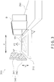
FIG. 3 is a view of the push-in mechanism illustrated inFIG. 2 as seen from the side. -
FIG. 4A is a view of a first step of a push-in action performed by the push-in mechanism illustrated inFIG. 2 . -
FIG. 4B is a view of a second step of the push-in action performed by the push-in mechanism illustrated inFIG. 2 . -
FIG. 4C is a view of a third step of the push-in action performed by the push-in mechanism illustrated inFIG. 2 . -
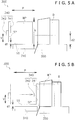
FIG. 5A is a view of a first step of a push-in action performed by a push-in mechanism mounted in the box packing device according to a first modified example 1A of the first embodiment of the present invention. -
FIG. 5B is a view of a second step of the push-in action performed by the push-in mechanism mounted in the box packing device according to the first modified example 1A of the first embodiment of the present invention. -
FIG. 6 is a perspective view of a push-in plate mounted in the box packing device according to a second modified example 1B of the first embodiment of the present invention. -
FIG. 7A is a view as seen from the side of a push-in mechanism mounted in the box packing device according to a third modified example 1C of the first embodiment of the present invention. -
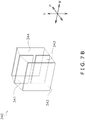
FIG. 7B is an oblique exploded view illustrating a push-in plate mounted in the box packing device according to the third modified example 1C of the first embodiment of the present invention. -
FIG. 7C is a perspective view of the push-in plate mounted in the box packing device according to the third modified example 1C of the first embodiment of the present invention. -
FIG. 7D is perspective view of the push-in plate mounted in the box packing device according to the third modified example 1C of the first embodiment of the present invention. -
FIG. 7E is a perspective view of the push-in plate mounted in the box packing device according to the third modified example 1C of the first embodiment of the present invention. -
FIG. 8 is a perspective view of a configuration of a box packing device according to a second embodiment of the present invention. -
FIG. 1 illustrates a configuration of abox packing device 500A according to a first embodiment of the present invention. Thebox packing device 500A receives articles WP wrapped in bags from a wrapping device one at a time and packs a predetermined number of the articles WP into a box. - The
box packing device 500A is provided with afeed mechanism 100, an accumulatingmechanism 200A, and a push-inmechanism 300. - The
feed mechanism 100 receives the articles WP wrapped in bags one at a time from an unillustrated wrapping device installed in the previous stage of thebox packing device 500A, feeds the articles WP in a feeding direction F1, and passes the articles WP on to the accumulatingmechanism 200A. - The
feed mechanism 100 has afeed conveyor belt 110 and adischarge conveyor belt 120. Thedischarge conveyor belt 120 is disposed in an inclined manner. - The accumulating
mechanism 200A accumulates a predetermined number of the articles WP. The accumulatingmechanism 200A has afirst conveyor belt 210 and asecond conveyor belt 220. Thefirst conveyor belt 210 is inclined with respect to the horizontal direction and forms a sloped surface. Thefirst conveyor belt 210 constantly operates. - The
second conveyor belt 220 is stopped or operates at a low speed until the predetermined number of the articles WP are accumulated. As a result, a plurality of the articles WP fed sequentially from thefeed mechanism 100 are accumulated on thesecond conveyor belt 220 in a partially overlapped manner. - When the predetermined number of the articles WP are accumulated, the
second conveyor belt 220 operates at a high speed and passes the group of the articles WP on to the push-inmechanism 300. - The push-in
mechanism 300 receives the predetermined number of articles WP accumulated by the accumulatingmechanism 200A, aligns the articles WP and packs the articles WP into a box. -
FIG. 2 illustrates a configuration of the push-inmechanism 300. The push-inmechanism 300 has anarticle placement part 310, astopper 320, asupport plate 330, a push-inplate 340, abox standby part 350, ahorizontal movement mechanism 360, and a lifting/lowering mechanism 370. - The
article placement part 310 is for placing one group of the articles WP to be boxed. Thearticle placement part 310 includes a conveyor belt and is able to feed the articles WP in a feeding direction F2. - As illustrated in
FIG. 3 , the upper surface of thearticle placement part 310 constitutes a placement surface SS regardless of the rotation state of the conveyor belt, and thearticle placement part 310 feeds one group of the articles WP received from the accumulatingmechanism 200A to the placement surface SS. - Returning to
FIG. 2 , thestopper 320 is a plate for blocking the movement of the front end of a group of the articles WP. Thesupport plate 330 is a plate for supporting the rear end of a group of the articles WP after the group of the articles WP is received by the push-inmechanism 300. Thestopper 320 and thesupport plate 330 are able to move appropriately for capturing and aligning a group of the articles WP. - The push-in
plate 340 is able to move or reciprocate in a reciprocating direction P due to thehorizontal movement mechanism 360. The push-inplate 340 has afirst plate 341 and asecond plate 342. Thefirst plate 341 is fixed to thehorizontal movement mechanism 360. Thesecond plate 342 is able to move relative to the first plate in a height direction V. - As illustrated in
FIG. 3 , the push-inplate 340 has a pressing surface SP, which is able to push a group of the articles WP. At least thesecond plate 342 has the pressing surface SP. The push-inplate 340 packs a group of the articles WP into a box B by moving closer to the box B. - Returning to
FIG. 2 , the box B opened at the side is placed on thebox standby part 350. Thebox standby part 350 has an unillustrated lifting/lowering mechanism so as to allow for lifting and lowering. The lifting/lowering mechanism moves the box B into which a group of the articles WP have been packed to a subsequent process and brings a new empty box B to the place where packing will be performed to it. - The
horizontal movement mechanism 360 moves the push-inplate 340 in the reciprocating direction P. Thehorizontal movement mechanism 360 has abeam 361 and a fixing member 362. Thefirst plate 341 of the push-inplate 340 is fixed to the fixing member 362. The fixing member 362 is moved in the reciprocating direction P along thebeam 361 by a drive mechanism which is not illustrated. - The lifting/
lowering mechanism 370 lifts and lowers thesecond plate 342 by moving thesecond plate 342 relative to thefirst plate 341 in the height direction V. The lifting/lowering mechanism 370 has aroller 371 and abelt 372. Theroller 371 is fixed to the fixing member 362 in a rotatable manner and is rotated by a motor which is not illustrated. Thebelt 372 has one end fixed to theroller 371 and the other end fixed to the second plate. Due to the force of the motor, theroller 371 winds thebelt 372 up or returns thebelt 372 whereby thesecond plate 342 is lifted or lowered. -
FIG. 4A to 4C illustrate push-in actions executed by the push-inmechanism 300. -
FIG. 4A illustrates the first step of the push-in action. - In this step, a group of the articles WP that has come from the accumulating
mechanism 200A (FIG. 1 ) is placed on the placement surface SS of thearticle placement part 310. At this time, thesecond plate 342 is lowered. As a result, the height of the placement surface SS and the height of the lower edge of the pressing surface SP are separated from each other by a first distance d1. -
FIG. 4B illustrates the second step of the push-in action. - In this step, the push-in
plate 340 moves toward the box B and consequently the pressing surface SP pushes the group of the articles WP toward the box B. As a result, the group of the articles WP is packed into the box B. The separation distance between the height of the placement surface SS and the height of the lower edge of the pressing surface SP is maintained at the first distance d1. -
FIG. 4C illustrates the third step of the push-in action. - In this step, the push-in
plate 340 returns to the location of the first step. At this time, thesecond plate 342 is lifted upward. As a result, the separation distance between the height of the placement surface SS and the height of the lower edge of the pressing surface SP becomes a second distance d2 which is greater than the first distance d1. As a result, the next group of the articles WP to be boxed can be placed on the placement surface SS without being hindered by the push-inplate 340. Thereafter, the push-in action returns to the first step. - The lifting/
lowering mechanism 370 in the push-inmechanism 300 is able to move the push-inplate 340 so that the distance separating the lower edge of the pressing surface SP and the placement surface SS in the height direction changes. Therefore, after the push-in action of the push-inplate 340 pushing the articles into the box B is finished, hindering of the movement of the next articles WP to be pushed into the box can be suppressed by increasing the height of the lower edge of the pressing surface SP. - The
first plate 341 is installed in a standing state and thesecond plate 342 is also installed in a standing state closer to the placement surface SS than thefirst plate 341. The pressing surface SP is present at least on thesecond plate 342. Thesecond plate 342 is moved in the height direction V by the lifting/lowering mechanism 370. Therefore, because the dimension in the height direction V of the push-inplate 340 can be extended and shrunk, the push-inmechanism 300 is able to handle articles WP of various sizes. - The lifting/
lowering mechanism 370 sets the separation distance to the first distance d1 when thehorizontal movement mechanism 360 moves the push-inplate 340 toward the box B. The lifting/lowering mechanism 370 sets the separation distance to the second distance d2, which is greater than the first distance d1, when thehorizontal movement mechanism 360 moves the push-inplate 340 away from the box B. Therefore, the movement of the next articles WP to be pushed into the same box B or a different new box B can be performed during the return action of the push-inplate 340, and consequently the speed of the push-in action can be improved. - The
box packing device 500A is provided with the push-inmechanism 300 having a fast processing speed. Therefore, the processing speed of thebox packing device 500A is improved. - The push-in
mechanism 300 mounted in thebox packing device 500A according to a first modified example 1A of the first embodiment changes the action of the lifting/lowering mechanism 370 according to the size of the article WP. - The
box packing device 500A according to the first modified example 1A is further provided with a detection means, which is not illustrated, for detecting the size of the article WP, specifically, the height h of the article WP. Thebox packing device 500A determines, on the basis of a signal from the detection means, whether the height h of the article WP is greater than the second distance d2 explained inFIG. 4C . - If the height h of the article WP is less than the second distance d2, the push-in
mechanism 300 according to the modified example 1A performs the push-in action including the steps illustrated inFIG. 4A to 4C in the same way as the push-inmechanism 300 according to the first embodiment. - On the other hand, if the height h of the article WP is equal to or greater than the second distance d2, the push-in
mechanism 300 according to the modified example 1A performs a push-in action including a first step inFIG. 5A and then a second step inFIG. 5B . - In the first step illustrated in
FIG. 5A , thesecond plate 342 is lowered and the height of the placement surface SS and the height of the lower edge of the pressing surface SP are separated from each other by the first distance d1. - In the second step illustrated in
FIG. 5B , the push-inplate 340 approaches the box B and consequently the pressing surface SP pushes the group of the articles WP toward the box B. Thefirst plate 341 contributes to the action of pushing the article WP. At this time, the height of the placement surface SS and the height of the lower edge of the pressing surface SP are still separated from each other by the first distance d1. - Next, without the lifting and lowering of the second plate being performed, the push-in
plate 340 is returned to the disposition inFIG. 5A . Thereafter, the next group of the articles WP to be boxed arrives at the placement surface SS, and then the first step is executed again. - According to this configuration, the
first plate 341 as well as thesecond plate 342 contribute to the action of pushing the article WP and therefore the article WP having the large height h can be packed into the box B in a stable manner. - The push-in
mechanism 300 mounted in thebox packing device 500A according to a second modified example 1B of the first embodiment extends and retracts the width of the push-inplate 340 according to the size of the article WP. -
FIG. 6 illustrates a configuration of the push-inplate 340 according to the second modified example 1B. The push-inplate 340 has afirst plate 341 and asecond plate 342. Thefirst plate 341 has a firstplate extension part 341a that allows for extension and retraction in the width direction W. Thesecond plate 342 similarly has a secondplate extension part 342a that allows for extension and retraction in the width direction W. The width direction W is a direction perpendicular to both the reciprocating direction P and the height direction V of the push-inplate 340. The extension and retraction is carried out automatically by an extending mechanism which is not illustrated. - Furthermore, the
box packing device 500A according to the second modified example 1B is further provided with a detecting means, which is not illustrated, for detecting the size of the article WP, specifically, the dimension in the feeding direction F2 (FIG. 2 ), namely, the dimension in the width direction W of the article WP. - According to this configuration, the width of the push-in
plate 340 can be increased due to the extension of the firstplate extension part 341a and the secondplate extension part 342a when handling the article WP having a dimension equal to or greater than a predetermined value. Therefore, the push-in action of a large article WP can be performed in a stable manner. - The push-in
mechanism 300 mounted in thebox packing device 500A according to a third modified example 1C of the first embodiment also extends and retracts the width of the push-inplate 340 according to the size of the article WP. -
FIG. 7A illustrates the push-inmechanism 300 according to the third modified example 1C. The push-inplate 340 of the push-inmechanism 300 has athird plate 343 and afourth plate 344 in addition to thefirst plate 341 and thesecond plate 342, and, as a result, differs from the first embodiment and the first modified example 1A and the second modified example 1B thereof. At least thesecond plate 342 among thefirst plate 341, thesecond plate 342, thethird plate 343, and thefourth plate 344 has the pressing surface SP. -
FIGS. 7B to 7E illustrate a configuration of the push-inplate 340 according to the third modified example 1C. As illustrated inFIG. 7B , the push-inplate 340 has a three-layer structure. The first layer includes thesecond plate 342. The second layer includes thefirst plate 341 and thethird plate 343. The third layer includes thefourth plate 344. Thefirst plate 341 is fixed to thehorizontal movement mechanism 360, which is not illustrated inFIG. 7B , in the same way the explained above with regard to the first embodiment, and the first modified example 1A and the second modified example 1B thereof. -
FIG. 7C illustrates the push-inplate 340 while thesecond plate 342 is lifted upward so as to approach thefirst plate 341. This form corresponds to the third step of the push-in action explained with reference toFIG. 4C . -
FIG. 7D illustrates the push-inplate 340 while thesecond plate 342 is lowered so as to approach the placement surface SS (FIG. 7A ). This form corresponds to the first step and the second step of the push-in action explained with reference toFIGS. 4A and4B . At this time, thethird plate 343 is also lowered with thesecond plate 342. -
FIG. 7E illustrates the push-inplate 340 that has been extended further in the width direction W. In comparison to the state illustrated inFIG. 7D , thethird plate 343 and thefourth plate 344 are moved relative to thefirst plate 341 and thesecond plate 342. Thefirst plate 341 and thethird plate 343 that similarly configure the second layer are present on the same plane. - The push-in
mechanism 300 mounted in thebox packing device 500A according to the third modified example 1C of the first embodiment does not have the lifting/lowering mechanism 370 of the first embodiment, and in place thereof, has an extension mechanism, which is not illustrated, for changing the form of the push-inplate 340 as illustrated inFIGS. 7C to 7E . - The
first plate 341, thesecond plate 342, thethird plate 343, and thefourth plate 344 are configured by thin plates having a thickness, for example, of 1.5 mm or less. Therefore, the step between thesecond plate 342 and thefourth plate 344 is a small dimension of 3.0 mm or less in the extended push-inplate 340 illustrated inFIG. 7E . - As illustrated in
FIG. 7A , when the push-inplate 340 pushes the article WP toward the box B, the push-inplate 340 is able to push the article WP with a uniform force because the step between thefirst plate 341, thesecond plate 342, thethird plate 343, and thefourth plate 344 is small. Therefore, the push-in action can be performed in a stable manner. -
FIG. 8 illustrates a configuration of abox packing device 500B according to a second embodiment of the present invention. An accumulatingmechanism 200B having a different configuration is mounted in thebox packing device 500B of the second embodiment in place of the accumulatingmechanism 200A mounted in thebox packing device 500A according to the first embodiment or the modified examples thereof. Thebox packing device 500B of the second embodiment is the same as thebox packing device 500A according to the first embodiment in the other aspects. - The accumulating
mechanism 200B differs from the accumulatingmechanism 200A according to the first embodiment in that the accumulatingmechanism 200B has athird conveyor belt 230 in addition to thefirst conveyor belt 210 and thesecond conveyor belt 220. - The
first conveyor belt 210 is inclined with respect to the horizontal direction and forms a sloped surface. Thefirst conveyor belt 210 constantly operates. - The
second conveyor belt 220 is stopped or operates at a low speed until the predetermined number of the articles WP are accumulated. As a result, a plurality of the articles WP fed sequentially from thefeed mechanism 100 are accumulated on thesecond conveyor belt 220 in a partially overlapping manner. - When the predetermined number of the articles WP are accumulated, the
second conveyor belt 220 operates at a high speed and passes the group of the articles WP on to thethird conveyor belt 230. - The
third conveyor belt 230 operates when predetermined conditions, such as the state of the subsequent push-inmechanism 300 and the like, are satisfied, and passes the group of the articles WP on to the push-inmechanism 300. - According to this configuration, the
third conveyor belt 230 functions as a buffer. When the push-inmechanism 300 is carrying out an action, thethird conveyor belt 230 is not able to pass the group of the articles WP on to the push-inmechanism 300 and therefore holds the group of the articles WP. During that time, the accumulatingmechanism 200B is able to execute the accumulation action by using thefirst conveyor belt 210 and thesecond conveyor belt 220. Therefore, the utilization rate of the accumulatingmechanism 200B is improved and the accumulatingmechanism 200B can avoid becoming a bottleneck in the production line. - The configurations of the push-in
mechanism 300 according to the first modified example 1A, the second modified example 1B, and the third modified example 1C of the first embodiment may be integrated with thebox packing device 500B according to the second embodiment. -
- B
- Box
- d1
- First distance
- d2
- Second distance
- SP
- Pressing surface
- SS
- Placement surface
- WP
- Article
- 100
- Feed mechanism
- 200A, 200B
- Accumulating mechanism
- 210
- First conveyor belt
- 220
- Second conveyor belt
- 230
- Third conveyor belt
- 300
- Push-in mechanism
- 310
- Article placement part (placement conveyor belt)
- 340
- Push-in plate
- 341
- First plate
- 342
- Second plate
- 343
- Third plate
- 344
- Fourth plate
- 360
- Horizontal movement mechanism
- 370
- Lifting/lowering mechanism
- 500A, 500B
- Box packing device
- Patent Document 1:
Japanese Patent Laid-open No. 2010-155648
Claims (7)
- A push-in mechanism for pushing articles into a box that is opened sideways, the push-in mechanism comprising:a box standby part configured to cause the box to wait;an article placement part having a placement surface on which the articles are temporarily placed;a push-in plate installed in a standing state so as to have a pressing surface configured to push the articles toward the box;a horizontal movement mechanism configured to reciprocate the push-in plate horizontally above the placement surface such that the push-in plate moves toward the box or moves away from the box; anda lifting/lowering mechanism configured to move the push-in plate so as to change a separation distance in the height direction between a lower edge of the pressing surface and the placement surface.
- The push-in mechanism according to claim 1, wherein:the push-in plate hasa first plate installed in a standing state, anda second plate installed in a standing state closer to the placement surface than the first plate and having the pressing surface, andthe lifting/lowering mechanism is configured to move the second plate in the height direction to change the separation distance.
- The push-in mechanism according to claim 1 or 2, wherein:the lifting/lowering mechanism is configured to set the separation distance to a first distance when the horizontal movement mechanism moves the push-in plate toward the box,the lifting/lowering mechanism is configured to set the separation distance to a second distance when the horizontal movement mechanism moves the push-in plate away from the box, andthe second distance is greater than the first distance.
- The push-in mechanism according to claim 1 or 2, wherein:the lifting/lowering mechanism is configured to set the separation distance to a first distance when the horizontal movement mechanism moves the push-in plate toward the box,the lifting/lowering mechanism is configured to set the separation distance to a second distance when the horizontal movement mechanism moves the push-in plate away from the box, andthe second distance is greater than the first distance when the size of the article is smaller than a predetermined size, andthe second distance is equal to the first distance when the size of the article is greater than the predetermined size.
- The push-in mechanism according to any one of claims 1 to 4, wherein:the push-in plate is configured to extend and retract in a width direction perpendicular to both of the reciprocating direction and the height direction of the push-in plates.
- A box packing device comprising:a feed mechanism configured to feed the articles in order one at a time;an accumulating mechanism configured to accumulate a predetermined number of the articles; andthe push-in mechanism according to any one of claims 1 to 5 configured to push the predetermined number of the articles into the box.
- The box packing device according to claim 6, wherein:the accumulating mechanism hasa first conveyor belt disposed in an inclined manner configured to receive the articles from the feed mechanism,a second conveyor belt configured to form an article group including the predetermined number of the articles, anda third conveyor belt configured to receive the article group from the second conveyor belt and temporarily hold the article group, andthe article placement part has a placement conveyor belt configured to receive the article group from the third conveyor belt and move the article group to the placement surface.
Applications Claiming Priority (2)
| Application Number | Priority Date | Filing Date | Title |
|---|---|---|---|
| JP2015010896A JP6534820B2 (en) | 2015-01-23 | 2015-01-23 | Push-in mechanism, and box packing device provided with the same |
| PCT/JP2015/078703 WO2016117178A1 (en) | 2015-01-23 | 2015-10-09 | Push-in mechanism and box packing device provided with same |
Publications (3)
| Publication Number | Publication Date |
|---|---|
| EP3248892A1 true EP3248892A1 (en) | 2017-11-29 |
| EP3248892A4 EP3248892A4 (en) | 2018-07-11 |
| EP3248892B1 EP3248892B1 (en) | 2020-04-08 |
Family
ID=56416740
Family Applications (1)
| Application Number | Title | Priority Date | Filing Date |
|---|---|---|---|
| EP15878867.9A Active EP3248892B1 (en) | 2015-01-23 | 2015-10-09 | Push-in mechanism and box packing device provided with same |
Country Status (5)
| Country | Link |
|---|---|
| US (1) | US10875674B2 (en) |
| EP (1) | EP3248892B1 (en) |
| JP (1) | JP6534820B2 (en) |
| CN (1) | CN107108055B (en) |
| WO (1) | WO2016117178A1 (en) |
Cited By (1)
| Publication number | Priority date | Publication date | Assignee | Title |
|---|---|---|---|---|
| EP4273052A1 (en) * | 2022-03-17 | 2023-11-08 | ISHIDA CO., Ltd. | Box packing apparatus |
Families Citing this family (16)
| Publication number | Priority date | Publication date | Assignee | Title |
|---|---|---|---|---|
| EP3284686B1 (en) * | 2016-08-16 | 2018-12-26 | Neopost Technologies | Device and method for assembling items for shipment |
| EP3354581B1 (en) * | 2017-01-31 | 2021-05-19 | Quadient Technologies France | System and method for automating packaging of varying shipment sets |
| CN107539508A (en) * | 2017-09-30 | 2018-01-05 | 苏州凯磊胜自动化科技有限公司 | Automate pen core bag with plurality boxing device and mounted box method |
| JP6967781B2 (en) * | 2018-02-22 | 2021-11-17 | 株式会社イシダ | Boxing device |
| US11214390B2 (en) | 2018-04-23 | 2022-01-04 | R.A Jones & Co. | Pouch containment and carton loading |
| CN109229460A (en) * | 2018-08-21 | 2019-01-18 | 博侃电气(合肥)有限公司 | A kind of batch piles up the shovel material device of workpiece |
| FR3087427B1 (en) * | 2018-10-19 | 2021-01-22 | Jacky Peterlini | DEVICE AND PROCEDURE FOR COLLECTING AND UNLOADING ITEMS |
| JP7042491B2 (en) * | 2018-12-13 | 2022-03-28 | オリオン機械工業株式会社 | Pusher |
| CN109606837A (en) * | 2019-01-29 | 2019-04-12 | 瑞安市天成包装机械有限公司 | Classification recrater |
| CN112340083B (en) * | 2020-11-26 | 2022-06-17 | 杭州卓良包装制品有限公司 | Machine-shaping plank vanning baling machine |
| NL2027175B1 (en) * | 2020-12-20 | 2022-07-15 | Blueprint Holding Bv | Article Packing Method and Apparatus |
| CN113650891A (en) * | 2021-08-03 | 2021-11-16 | 泉州市泉创智能设备有限公司 | Material arranging device for wet tissue packing machine and box filling machine |
| CN114435672B (en) * | 2021-12-27 | 2024-10-22 | 重庆中烟工业有限责任公司 | A pack pushing mechanism for cigarette packing machine |
| CN114771937B (en) * | 2022-05-05 | 2024-05-17 | 南通烟滤嘴有限责任公司 | Filter rod stacking and shaping device |
| JP7740156B2 (en) * | 2022-07-28 | 2025-09-17 | 王子ホールディングス株式会社 | Conveyor |
| JP2025119359A (en) | 2024-02-01 | 2025-08-14 | 株式会社イシダ | Pushing mechanism and boxing device |
Family Cites Families (40)
| Publication number | Priority date | Publication date | Assignee | Title |
|---|---|---|---|---|
| US2024503A (en) * | 1933-11-13 | 1935-12-17 | Percy D Bickford | Carton filling machine |
| US2651442A (en) * | 1950-08-29 | 1953-09-08 | Redington Co F B | Carton filling machine |
| US2857721A (en) * | 1955-02-04 | 1958-10-28 | Emhart Mfg Co | Packing machines for cans or the like |
| US2972842A (en) * | 1956-10-12 | 1961-02-28 | Eugene B Hitchcock | Can packaging method and machine |
| US2985321A (en) * | 1958-01-14 | 1961-05-23 | Emhart Mfg Co | Case packer |
| US3039248A (en) * | 1958-09-15 | 1962-06-19 | R A Jones And Company Inc | Automatic case packing machine |
| US3041803A (en) | 1960-03-08 | 1962-07-03 | American Mach & Foundry | Cartoning machine |
| US3220158A (en) * | 1962-09-06 | 1965-11-30 | Thiele Eng Co | Product arranger |
| US3269091A (en) * | 1962-09-19 | 1966-08-30 | Bartelt Engineering Co Inc | Cartoning machine |
| GB1055611A (en) * | 1964-09-08 | 1967-01-18 | Metal Box Co Ltd | Improvements in or relating to apparatus for loading articles in rows on a supporting base |
| US3516220A (en) * | 1965-01-11 | 1970-06-23 | Charles Gilbert Buford | Container filling apparatus |
| US3410049A (en) | 1965-09-03 | 1968-11-12 | Western Corrugated Inc | Can loading machine |
| GB1183042A (en) * | 1966-02-16 | 1970-03-04 | Robinson E S & A Ltd | Carton Forming and Filling Machine |
| CA918114A (en) * | 1970-01-27 | 1973-01-02 | Polymer Corporation Limited | Carton packing device |
| US3914921A (en) * | 1974-04-10 | 1975-10-28 | Windor Inc | High speed carton casing apparatus |
| IT1105580B (en) * | 1978-06-06 | 1985-11-04 | Azionaria Costruzioni Acma Spa | EQUIPMENT FOR THE TRANSFER OF ENVELOPES AND THEIR INTRODUCTION IN BOXES |
| JP2528059B2 (en) * | 1992-08-01 | 1996-08-28 | 協同組合タツノハイテック | Box packing equipment |
| DE19838076B4 (en) * | 1998-08-21 | 2010-10-28 | Focke & Co.(Gmbh & Co. Kg) | Method and device for producing (large) packs |
| JP3974409B2 (en) | 2002-01-22 | 2007-09-12 | 株式会社イシダ | Conveying device and boxing device provided with the same |
| GB0201981D0 (en) * | 2002-01-29 | 2002-03-13 | Bradman Lake Ltd | Improvements relating to carton filling apparatus |
| CA2574681A1 (en) * | 2004-07-22 | 2006-02-02 | Pulsar S.R.L. | Apparatus for packing groups of items |
| DE102004050197A1 (en) * | 2004-10-15 | 2006-04-20 | Iwk Verpackungstechnik Gmbh | Feeder for packing stacks of blister packs in cartons has dividers mounted on conveyor which fit against sides of stack, top cover fitting on stack which is made up of sections with gaps, through which dividers can pass |
| US7073310B1 (en) * | 2004-12-27 | 2006-07-11 | Kimberly-Clark Worldwide, Inc. | Flexible carton loading apparatus |
| ES2310444B1 (en) * | 2006-04-12 | 2009-10-26 | Graphic Packaging International Inc. | "SYSTEM OF SUSPENDED CENTERING TOPES, FOR PACKING MACHINE". |
| NL1032449C2 (en) * | 2006-09-06 | 2008-03-07 | Robert Bosch Verpakkingsmachin | Device for packaging objects in a box as well as such a method. |
| AU2007295381A1 (en) * | 2006-09-15 | 2008-03-20 | Ishida Co., Ltd. | Conveying device, and boxing device and boxing system provided with the same |
| ATE549155T1 (en) * | 2007-12-21 | 2012-03-15 | Rockwool Int | APPARATUS AND METHOD FOR PACKAGING ARTICLES |
| US20110036055A1 (en) * | 2008-02-28 | 2011-02-17 | Uni-Charn Corporation | Pusher used in packaging equipment |
| ITTO20080318A1 (en) * | 2008-04-24 | 2009-10-25 | Elsag Datamat Spa | POSTAL OBJECT TREATMENT DEVICE PACKED |
| US20090290961A1 (en) * | 2008-05-13 | 2009-11-26 | Macy Langston | Product packaging system and method |
| JP5514524B2 (en) * | 2009-11-30 | 2014-06-04 | 株式会社イシダ | Package conveyor |
| JP2010155648A (en) | 2009-01-05 | 2010-07-15 | Ishida Co Ltd | Attitude changing device |
| JP5889517B2 (en) | 2010-04-08 | 2016-03-22 | 株式会社イシダ | Boxing device with turning device |
| US20120006651A1 (en) | 2010-07-12 | 2012-01-12 | Frito-Lay North America, Inc. | Robotic row collector |
| EP2716550B1 (en) * | 2011-06-02 | 2016-01-20 | Ishida Co., Ltd. | Box-packing device |
| WO2013121550A1 (en) * | 2012-02-16 | 2013-08-22 | 日本たばこ産業株式会社 | Machine for packing article into box |
| DE102012204013B4 (en) * | 2012-03-14 | 2025-10-02 | Krones Aktiengesellschaft | Method and device for transferring article layers between adjacent modules |
| EP3296237B1 (en) * | 2012-10-03 | 2019-05-29 | Amazon Technologies, Inc. | Functional trays for handling products in a materials handling facility |
| CN202988290U (en) * | 2012-11-27 | 2013-06-12 | 深圳市木森科技有限公司 | Stacking device |
| CN103770961B (en) * | 2014-01-10 | 2015-09-30 | 杭州中亚机械股份有限公司 | Stacked article storage device and article laminating method |
-
2015
- 2015-01-23 JP JP2015010896A patent/JP6534820B2/en active Active
- 2015-10-09 EP EP15878867.9A patent/EP3248892B1/en active Active
- 2015-10-09 US US15/541,530 patent/US10875674B2/en active Active
- 2015-10-09 CN CN201580071298.8A patent/CN107108055B/en active Active
- 2015-10-09 WO PCT/JP2015/078703 patent/WO2016117178A1/en not_active Ceased
Cited By (2)
| Publication number | Priority date | Publication date | Assignee | Title |
|---|---|---|---|---|
| EP4273052A1 (en) * | 2022-03-17 | 2023-11-08 | ISHIDA CO., Ltd. | Box packing apparatus |
| US12017812B2 (en) | 2022-03-17 | 2024-06-25 | Ishida Co., Ltd. | Box packing apparatus |
Also Published As
| Publication number | Publication date |
|---|---|
| EP3248892A4 (en) | 2018-07-11 |
| JP6534820B2 (en) | 2019-06-26 |
| US10875674B2 (en) | 2020-12-29 |
| WO2016117178A1 (en) | 2016-07-28 |
| CN107108055A (en) | 2017-08-29 |
| CN107108055B (en) | 2019-08-20 |
| US20180016043A1 (en) | 2018-01-18 |
| JP2016135679A (en) | 2016-07-28 |
| EP3248892B1 (en) | 2020-04-08 |
Similar Documents
| Publication | Publication Date | Title |
|---|---|---|
| EP3248892B1 (en) | Push-in mechanism and box packing device provided with same | |
| CN104261078B (en) | Three pallet-free storehouse, piling position palletizing apparatus on a kind of piling transfer limes | |
| EP3277589B1 (en) | System and method for forming a custom-sized package | |
| US10414607B2 (en) | Portioning system for portioning stackable flat elements in a stack for a further processing | |
| ITMI941885A1 (en) | EQUIPMENT FOR MAKING PRODUCTS COMING FROM MULTIPLE LANES | |
| EP4566955A2 (en) | A machinery and method to handle a stack of folded items | |
| EP1129843B1 (en) | Method and machine for separating blanks for cardboard boxes | |
| US10618738B2 (en) | Multichannel feeding system | |
| CN213833704U (en) | Carton board conveying structure | |
| CN210822984U (en) | Distributing channel and vibrating distributing device | |
| CN213474450U (en) | Double-box synchronous grabbing and positioning mechanism on production line | |
| CN211055526U (en) | Automatic boxing device | |
| CN206358920U (en) | Tablet collecting device and its feed bin | |
| EP3481759A1 (en) | Carton stack divider and a method for dividing a pack of flat-folded cartons | |
| CN215792072U (en) | Counting device of box pasting machine | |
| CN223267830U (en) | Sheet box unloading device and folding box production line with the same | |
| JPH0130423Y2 (en) | ||
| JP5996043B1 (en) | Integrated transport device | |
| CN216360088U (en) | Tray for plastic uptake box consignment | |
| CN223254531U (en) | Corrugated board transfer device | |
| CN204433830U (en) | Plastics core lifting material feeding mechanism | |
| CN215156051U (en) | Packagine machine processing material conveyor | |
| CN208747084U (en) | A kind of automatic material receiving and changing box equipment | |
| CN108482969B (en) | multi-channel feeding system | |
| JP3159164B2 (en) | Integrated device |
Legal Events
| Date | Code | Title | Description |
|---|---|---|---|
| STAA | Information on the status of an ep patent application or granted ep patent |
Free format text: STATUS: THE INTERNATIONAL PUBLICATION HAS BEEN MADE |
|
| PUAI | Public reference made under article 153(3) epc to a published international application that has entered the european phase |
Free format text: ORIGINAL CODE: 0009012 |
|
| STAA | Information on the status of an ep patent application or granted ep patent |
Free format text: STATUS: REQUEST FOR EXAMINATION WAS MADE |
|
| 17P | Request for examination filed |
Effective date: 20170728 |
|
| AK | Designated contracting states |
Kind code of ref document: A1 Designated state(s): AL AT BE BG CH CY CZ DE DK EE ES FI FR GB GR HR HU IE IS IT LI LT LU LV MC MK MT NL NO PL PT RO RS SE SI SK SM TR |
|
| AX | Request for extension of the european patent |
Extension state: BA ME |
|
| DAV | Request for validation of the european patent (deleted) | ||
| DAX | Request for extension of the european patent (deleted) | ||
| A4 | Supplementary search report drawn up and despatched |
Effective date: 20180607 |
|
| RIC1 | Information provided on ipc code assigned before grant |
Ipc: B65B 5/10 20060101ALI20180601BHEP Ipc: B65B 35/40 20060101AFI20180601BHEP |
|
| STAA | Information on the status of an ep patent application or granted ep patent |
Free format text: STATUS: EXAMINATION IS IN PROGRESS |
|
| 17Q | First examination report despatched |
Effective date: 20190617 |
|
| GRAP | Despatch of communication of intention to grant a patent |
Free format text: ORIGINAL CODE: EPIDOSNIGR1 |
|
| STAA | Information on the status of an ep patent application or granted ep patent |
Free format text: STATUS: GRANT OF PATENT IS INTENDED |
|
| INTG | Intention to grant announced |
Effective date: 20191127 |
|
| GRAS | Grant fee paid |
Free format text: ORIGINAL CODE: EPIDOSNIGR3 |
|
| GRAA | (expected) grant |
Free format text: ORIGINAL CODE: 0009210 |
|
| STAA | Information on the status of an ep patent application or granted ep patent |
Free format text: STATUS: THE PATENT HAS BEEN GRANTED |
|
| AK | Designated contracting states |
Kind code of ref document: B1 Designated state(s): AL AT BE BG CH CY CZ DE DK EE ES FI FR GB GR HR HU IE IS IT LI LT LU LV MC MK MT NL NO PL PT RO RS SE SI SK SM TR |
|
| REG | Reference to a national code |
Ref country code: CH Ref legal event code: EP Ref country code: AT Ref legal event code: REF Ref document number: 1254075 Country of ref document: AT Kind code of ref document: T Effective date: 20200415 |
|
| REG | Reference to a national code |
Ref country code: DE Ref legal event code: R096 Ref document number: 602015050533 Country of ref document: DE |
|
| REG | Reference to a national code |
Ref country code: IE Ref legal event code: FG4D |
|
| REG | Reference to a national code |
Ref country code: NL Ref legal event code: FP |
|
| REG | Reference to a national code |
Ref country code: NO Ref legal event code: T2 Effective date: 20200408 |
|
| REG | Reference to a national code |
Ref country code: LT Ref legal event code: MG4D |
|
| PG25 | Lapsed in a contracting state [announced via postgrant information from national office to epo] |
Ref country code: SE Free format text: LAPSE BECAUSE OF FAILURE TO SUBMIT A TRANSLATION OF THE DESCRIPTION OR TO PAY THE FEE WITHIN THE PRESCRIBED TIME-LIMIT Effective date: 20200408 Ref country code: LT Free format text: LAPSE BECAUSE OF FAILURE TO SUBMIT A TRANSLATION OF THE DESCRIPTION OR TO PAY THE FEE WITHIN THE PRESCRIBED TIME-LIMIT Effective date: 20200408 Ref country code: IS Free format text: LAPSE BECAUSE OF FAILURE TO SUBMIT A TRANSLATION OF THE DESCRIPTION OR TO PAY THE FEE WITHIN THE PRESCRIBED TIME-LIMIT Effective date: 20200808 Ref country code: FI Free format text: LAPSE BECAUSE OF FAILURE TO SUBMIT A TRANSLATION OF THE DESCRIPTION OR TO PAY THE FEE WITHIN THE PRESCRIBED TIME-LIMIT Effective date: 20200408 Ref country code: PT Free format text: LAPSE BECAUSE OF FAILURE TO SUBMIT A TRANSLATION OF THE DESCRIPTION OR TO PAY THE FEE WITHIN THE PRESCRIBED TIME-LIMIT Effective date: 20200817 Ref country code: GR Free format text: LAPSE BECAUSE OF FAILURE TO SUBMIT A TRANSLATION OF THE DESCRIPTION OR TO PAY THE FEE WITHIN THE PRESCRIBED TIME-LIMIT Effective date: 20200709 |
|
| REG | Reference to a national code |
Ref country code: AT Ref legal event code: MK05 Ref document number: 1254075 Country of ref document: AT Kind code of ref document: T Effective date: 20200408 |
|
| PG25 | Lapsed in a contracting state [announced via postgrant information from national office to epo] |
Ref country code: LV Free format text: LAPSE BECAUSE OF FAILURE TO SUBMIT A TRANSLATION OF THE DESCRIPTION OR TO PAY THE FEE WITHIN THE PRESCRIBED TIME-LIMIT Effective date: 20200408 Ref country code: RS Free format text: LAPSE BECAUSE OF FAILURE TO SUBMIT A TRANSLATION OF THE DESCRIPTION OR TO PAY THE FEE WITHIN THE PRESCRIBED TIME-LIMIT Effective date: 20200408 Ref country code: BG Free format text: LAPSE BECAUSE OF FAILURE TO SUBMIT A TRANSLATION OF THE DESCRIPTION OR TO PAY THE FEE WITHIN THE PRESCRIBED TIME-LIMIT Effective date: 20200708 Ref country code: HR Free format text: LAPSE BECAUSE OF FAILURE TO SUBMIT A TRANSLATION OF THE DESCRIPTION OR TO PAY THE FEE WITHIN THE PRESCRIBED TIME-LIMIT Effective date: 20200408 |
|
| PG25 | Lapsed in a contracting state [announced via postgrant information from national office to epo] |
Ref country code: AL Free format text: LAPSE BECAUSE OF FAILURE TO SUBMIT A TRANSLATION OF THE DESCRIPTION OR TO PAY THE FEE WITHIN THE PRESCRIBED TIME-LIMIT Effective date: 20200408 |
|
| REG | Reference to a national code |
Ref country code: DE Ref legal event code: R097 Ref document number: 602015050533 Country of ref document: DE |
|
| PG25 | Lapsed in a contracting state [announced via postgrant information from national office to epo] |
Ref country code: CZ Free format text: LAPSE BECAUSE OF FAILURE TO SUBMIT A TRANSLATION OF THE DESCRIPTION OR TO PAY THE FEE WITHIN THE PRESCRIBED TIME-LIMIT Effective date: 20200408 Ref country code: IT Free format text: LAPSE BECAUSE OF FAILURE TO SUBMIT A TRANSLATION OF THE DESCRIPTION OR TO PAY THE FEE WITHIN THE PRESCRIBED TIME-LIMIT Effective date: 20200408 Ref country code: RO Free format text: LAPSE BECAUSE OF FAILURE TO SUBMIT A TRANSLATION OF THE DESCRIPTION OR TO PAY THE FEE WITHIN THE PRESCRIBED TIME-LIMIT Effective date: 20200408 Ref country code: ES Free format text: LAPSE BECAUSE OF FAILURE TO SUBMIT A TRANSLATION OF THE DESCRIPTION OR TO PAY THE FEE WITHIN THE PRESCRIBED TIME-LIMIT Effective date: 20200408 Ref country code: SM Free format text: LAPSE BECAUSE OF FAILURE TO SUBMIT A TRANSLATION OF THE DESCRIPTION OR TO PAY THE FEE WITHIN THE PRESCRIBED TIME-LIMIT Effective date: 20200408 Ref country code: EE Free format text: LAPSE BECAUSE OF FAILURE TO SUBMIT A TRANSLATION OF THE DESCRIPTION OR TO PAY THE FEE WITHIN THE PRESCRIBED TIME-LIMIT Effective date: 20200408 Ref country code: DK Free format text: LAPSE BECAUSE OF FAILURE TO SUBMIT A TRANSLATION OF THE DESCRIPTION OR TO PAY THE FEE WITHIN THE PRESCRIBED TIME-LIMIT Effective date: 20200408 Ref country code: AT Free format text: LAPSE BECAUSE OF FAILURE TO SUBMIT A TRANSLATION OF THE DESCRIPTION OR TO PAY THE FEE WITHIN THE PRESCRIBED TIME-LIMIT Effective date: 20200408 |
|
| PLBE | No opposition filed within time limit |
Free format text: ORIGINAL CODE: 0009261 |
|
| STAA | Information on the status of an ep patent application or granted ep patent |
Free format text: STATUS: NO OPPOSITION FILED WITHIN TIME LIMIT |
|
| PG25 | Lapsed in a contracting state [announced via postgrant information from national office to epo] |
Ref country code: SK Free format text: LAPSE BECAUSE OF FAILURE TO SUBMIT A TRANSLATION OF THE DESCRIPTION OR TO PAY THE FEE WITHIN THE PRESCRIBED TIME-LIMIT Effective date: 20200408 Ref country code: PL Free format text: LAPSE BECAUSE OF FAILURE TO SUBMIT A TRANSLATION OF THE DESCRIPTION OR TO PAY THE FEE WITHIN THE PRESCRIBED TIME-LIMIT Effective date: 20200408 |
|
| 26N | No opposition filed |
Effective date: 20210112 |
|
| PG25 | Lapsed in a contracting state [announced via postgrant information from national office to epo] |
Ref country code: SI Free format text: LAPSE BECAUSE OF FAILURE TO SUBMIT A TRANSLATION OF THE DESCRIPTION OR TO PAY THE FEE WITHIN THE PRESCRIBED TIME-LIMIT Effective date: 20200408 |
|
| REG | Reference to a national code |
Ref country code: CH Ref legal event code: PL |
|
| PG25 | Lapsed in a contracting state [announced via postgrant information from national office to epo] |
Ref country code: LU Free format text: LAPSE BECAUSE OF NON-PAYMENT OF DUE FEES Effective date: 20201009 Ref country code: MC Free format text: LAPSE BECAUSE OF FAILURE TO SUBMIT A TRANSLATION OF THE DESCRIPTION OR TO PAY THE FEE WITHIN THE PRESCRIBED TIME-LIMIT Effective date: 20200408 |
|
| REG | Reference to a national code |
Ref country code: BE Ref legal event code: MM Effective date: 20201031 |
|
| PG25 | Lapsed in a contracting state [announced via postgrant information from national office to epo] |
Ref country code: FR Free format text: LAPSE BECAUSE OF NON-PAYMENT OF DUE FEES Effective date: 20201031 |
|
| PG25 | Lapsed in a contracting state [announced via postgrant information from national office to epo] |
Ref country code: BE Free format text: LAPSE BECAUSE OF NON-PAYMENT OF DUE FEES Effective date: 20201031 Ref country code: CH Free format text: LAPSE BECAUSE OF NON-PAYMENT OF DUE FEES Effective date: 20201031 Ref country code: LI Free format text: LAPSE BECAUSE OF NON-PAYMENT OF DUE FEES Effective date: 20201031 |
|
| PG25 | Lapsed in a contracting state [announced via postgrant information from national office to epo] |
Ref country code: IE Free format text: LAPSE BECAUSE OF NON-PAYMENT OF DUE FEES Effective date: 20201009 |
|
| PG25 | Lapsed in a contracting state [announced via postgrant information from national office to epo] |
Ref country code: TR Free format text: LAPSE BECAUSE OF FAILURE TO SUBMIT A TRANSLATION OF THE DESCRIPTION OR TO PAY THE FEE WITHIN THE PRESCRIBED TIME-LIMIT Effective date: 20200408 Ref country code: MT Free format text: LAPSE BECAUSE OF FAILURE TO SUBMIT A TRANSLATION OF THE DESCRIPTION OR TO PAY THE FEE WITHIN THE PRESCRIBED TIME-LIMIT Effective date: 20200408 Ref country code: CY Free format text: LAPSE BECAUSE OF FAILURE TO SUBMIT A TRANSLATION OF THE DESCRIPTION OR TO PAY THE FEE WITHIN THE PRESCRIBED TIME-LIMIT Effective date: 20200408 |
|
| PG25 | Lapsed in a contracting state [announced via postgrant information from national office to epo] |
Ref country code: MK Free format text: LAPSE BECAUSE OF FAILURE TO SUBMIT A TRANSLATION OF THE DESCRIPTION OR TO PAY THE FEE WITHIN THE PRESCRIBED TIME-LIMIT Effective date: 20200408 |
|
| PGFP | Annual fee paid to national office [announced via postgrant information from national office to epo] |
Ref country code: NL Payment date: 20251023 Year of fee payment: 11 |
|
| PGFP | Annual fee paid to national office [announced via postgrant information from national office to epo] |
Ref country code: DE Payment date: 20251020 Year of fee payment: 11 |
|
| PGFP | Annual fee paid to national office [announced via postgrant information from national office to epo] |
Ref country code: GB Payment date: 20251024 Year of fee payment: 11 |
|
| PGFP | Annual fee paid to national office [announced via postgrant information from national office to epo] |
Ref country code: NO Payment date: 20251022 Year of fee payment: 11 |