EP1129843B1 - Method and machine for separating blanks for cardboard boxes - Google Patents
Method and machine for separating blanks for cardboard boxes Download PDFInfo
- Publication number
- EP1129843B1 EP1129843B1 EP00200767A EP00200767A EP1129843B1 EP 1129843 B1 EP1129843 B1 EP 1129843B1 EP 00200767 A EP00200767 A EP 00200767A EP 00200767 A EP00200767 A EP 00200767A EP 1129843 B1 EP1129843 B1 EP 1129843B1
- Authority
- EP
- European Patent Office
- Prior art keywords
- sheets
- unbroken
- lip
- blanks
- teeth
- Prior art date
- Legal status (The legal status is an assumption and is not a legal conclusion. Google has not performed a legal analysis and makes no representation as to the accuracy of the status listed.)
- Expired - Lifetime
Links
Images


Classifications
-
- B—PERFORMING OPERATIONS; TRANSPORTING
- B65—CONVEYING; PACKING; STORING; HANDLING THIN OR FILAMENTARY MATERIAL
- B65H—HANDLING THIN OR FILAMENTARY MATERIAL, e.g. SHEETS, WEBS, CABLES
- B65H3/00—Separating articles from piles
- B65H3/32—Separating articles from piles by elements, e.g. fingers, plates, rollers, inserted or traversed between articles to be separated and remainder of the pile
- B65H3/322—Separating articles from piles by elements, e.g. fingers, plates, rollers, inserted or traversed between articles to be separated and remainder of the pile for separating a part of the pile, i.e. several articles at once
-
- B—PERFORMING OPERATIONS; TRANSPORTING
- B26—HAND CUTTING TOOLS; CUTTING; SEVERING
- B26D—CUTTING; DETAILS COMMON TO MACHINES FOR PERFORATING, PUNCHING, CUTTING-OUT, STAMPING-OUT OR SEVERING
- B26D7/00—Details of apparatus for cutting, cutting-out, stamping-out, punching, perforating, or severing by means other than cutting
- B26D7/18—Means for removing cut-out material or waste
- B26D7/1827—Means for removing cut-out material or waste by tearing
-
- B—PERFORMING OPERATIONS; TRANSPORTING
- B65—CONVEYING; PACKING; STORING; HANDLING THIN OR FILAMENTARY MATERIAL
- B65H—HANDLING THIN OR FILAMENTARY MATERIAL, e.g. SHEETS, WEBS, CABLES
- B65H31/00—Pile receivers
- B65H31/30—Arrangements for removing completed piles
- B65H31/3054—Arrangements for removing completed piles by moving the surface supporting the lowermost article of the pile, e.g. by using belts or rollers
- B65H31/3063—Arrangements for removing completed piles by moving the surface supporting the lowermost article of the pile, e.g. by using belts or rollers by special supports like carriages, containers, trays, compartments, plates or bars, e.g. moved in a closed loop
-
- B—PERFORMING OPERATIONS; TRANSPORTING
- B31—MAKING ARTICLES OF PAPER, CARDBOARD OR MATERIAL WORKED IN A MANNER ANALOGOUS TO PAPER; WORKING PAPER, CARDBOARD OR MATERIAL WORKED IN A MANNER ANALOGOUS TO PAPER
- B31B—MAKING CONTAINERS OF PAPER, CARDBOARD OR MATERIAL WORKED IN A MANNER ANALOGOUS TO PAPER
- B31B50/00—Making rigid or semi-rigid containers, e.g. boxes or cartons
- B31B50/002—Prebreaking
-
- B—PERFORMING OPERATIONS; TRANSPORTING
- B31—MAKING ARTICLES OF PAPER, CARDBOARD OR MATERIAL WORKED IN A MANNER ANALOGOUS TO PAPER; WORKING PAPER, CARDBOARD OR MATERIAL WORKED IN A MANNER ANALOGOUS TO PAPER
- B31B—MAKING CONTAINERS OF PAPER, CARDBOARD OR MATERIAL WORKED IN A MANNER ANALOGOUS TO PAPER
- B31B50/00—Making rigid or semi-rigid containers, e.g. boxes or cartons
- B31B50/02—Feeding or positioning sheets, blanks or webs
- B31B50/04—Feeding sheets or blanks
- B31B50/06—Feeding sheets or blanks from stacks
Definitions
- the invention relates to a method for separating blanks for cardboard boxes, in particular packaging boxes, from unbroken board sheets which each comprise a number of blanks which are connected to one another along breaking lines, in which method:
- a starting sheet of corrugated board is, where necessary, provided with text and/or pictures (by printing or processing preprinted sheets).
- a number of blanks which are still connected to one another along breaking lines, are formed in the starting sheet.
- Such a sheet having a number of blanks which are connected to one another along breaking lines is known as "an unbroken sheet”.
- each unbroken sheet is broken into separate blanks. This breaking may take place manually or, if appropriate, mechanically. Breaking is extremely easy, since the breaking lines are already such that the blanks can break free along the breaking lines if the unbroken sheet is picked up.
- the separated blanks are then manually or mechanically formed into stacks of blanks, which stacks of blanks are then generally packaged further, for example by wrapping a sheet around them, by winding a wire around them or by placing the stacks of blanks in an outer box. All this generally takes place at the premises of the supplier, also known as the "packaging producer", of the packaging box.
- the stacks of blanks are then transported to the location where the blanks are formed into boxes, which are then filled.
- the packaging producer operates somewhat differently.
- the blanks are generally formed directly from the starting sheet by punching. In this case, therefore, there is no formation of a so-called unbroken sheet which is broken into separate blanks in a subsequent breaking step (although this method does exist). Therefore, the separation of the blanks takes place directly during punching. Afterwards, the blanks are again formed into stacks of blanks which can be packaged and made available to the purchaser.
- the drawback of the method outlined above is that the packaging producer, as the purchaser's supplier, must have a large production capacity in order to be able to supply blanks sufficiently quickly at all times in particular in the event of highly fluctuating demand from the purchaser. Such a situation arises, for example, with boxes for packaging seasonal products, such as ice creams. Ice creams are typically products which are produced and therefore also packaged primarily in the summer season and for which, in addition, demand is very strongly influenced by the weather at the time. If the packaging producer, as supplier, then wants to be able to keep up with a high demand, he must either have or have in reserve sufficiently great production capacity or must have sufficient stocks of stacks containing separate blanks.
- the second drawback of the current method is that the process steps may influence one another. For example, a fault during the formation of stacks of blanks may have a direct effect on the stamping and printing process.
- the object of the present invention is to provide a method for separating blanks for cardboard boxes which, inter alia, offers a solution to the above problems.
- this object is achieved by, in a step a) (before step c), stacking the unbroken sheets to form a stack of sheets.
- a stack of sheets is understood to mean a stack of unbroken sheets.
- this stacking to form a stack of sheets offers the advantage that, if it is desired for the separation or, if appropriate, the use of the blanks to take place in line with the operation of forming blanks from starting sheets, the separation step can be made independent of the preceding forming step, by forming a buffer, i.e. the stack of sheets. This means that, in the event of stagnation in the separation process or a subsequent process, the previous forming process can continue to operate, or in the event of stagnation in the forming process the subsequent separating process or further process can continue.
- the method according to the invention can be used both for boxes, or more correctly blanks, made from corrugated board and for boxes or blanks made from solid board.
- the punching device will have to be suitable for the production of unbroken board sheets with blanks which are connected to one another via breaking lines.
- the production of pieces of solid board which are connected to one another via breaking lines is not per se anything special and is already known from the prior art.
- one or more stacks of sheets not only makes it possible to form a buffer, but also, instead or in addition, also makes it possible to render the separation process more efficient, by, in step c), breaking the stack of sheets or a partial stack of sheets into separated partial stacks of blanks. It is thus possible for the entire stack of sheets to undergo the breaking step all at once, instead of sheet by sheet, which may then result in correspondingly high stacks of separated blanks, referred to as partial stacks of blanks. It is also conceivable for part, known as a partial stack of sheets, to be removed from the stack of sheets and subjected to the breaking process all at once. In this case too, the breaking of a partial stack of sheets may then result in correspondingly high separated partial stacks of blanks.
- step a If the entire stack of sheets is subjected to a breaking step all at once, in line with the forming process which precedes the breaking process, the abovementioned buffer effect will be, at least partially, lost, unless a plurality of successive stacks of blanks are ready. However, partial stacks of blanks are still easier to handle than each blank separately. If in each case a partial stack of sheets from a stack of sheets is subjected to the breaking process (step a)), the remaining stack of sheets will continue to act as a buffer.
- forming stacks of unbroken sheets not only makes it possible, in an in-line situation, to make the operation of step c) less dependent on the preceding forming process, but also makes it possible to provide a solution to the abovementioned problems by decoupling the separation process from the forming process (in which unbroken board sheets are formed from starting sheets) entirely.
- This is because, in the first instance, it is possible to form stacks of unbroken board sheets (which each in turn comprise a number of blanks connected to one another along breaking lines), and to hold these stacks in stock for a longer or shorter time.
- Stock stacks of this nature take up less space than stacks of blanks which have already been separated and, moreover, tie up less capital.
- step b) can, according to the invention, be carried out in an advantageous manner, preferably automatically, by firstly inserting a lip beneath the sheet which is to be removed or the bottom sheet of the partial stack of sheets which is to be removed, preferably approximately in the centre of a longitudinal or transverse side of the stack of sheets, and by lifting the said sheet or the said bottom sheet of the partial stack of sheets, in such a manner that a gap is formed on either side of the lip, and by inserting a first tooth into the said gap on either side of the lip and using these first teeth to increase the length of the gap, measured from the lip, on either side of the lip, by inserting in each case a second tooth into the gap on the outer sides, remote from one another, of the first teeth, which has been enlarged in this way, and by fitting the teeth all the way through beneath the said sheet or the said partial stack of sheets.
- the unbroken sheets can be carefully removed from the stack of sheets without prematurely breaking along the breaking line.
- This has the advantage that it is consequently possible to feed the unbroken board sheets accurately and in a predetermined manner to a breaking process, preferably an automated breaking process. This is of benefit to the reliability and speed of the entire process.
- the board sheets may comprise blanks of two or more different types and, after step c) and before any step d), the blanks are sorted according to type and, in any such step d), stacks of blanks are formed for each type containing blanks of the said type, and if appropriate these stacks of blanks are packaged. It thus becomes possible for the unbroken sheets, with regard to the space which they take up, to be divided as efficiently as possible and, if various types of blanks are arranged on these sheets, for these various types of blanks still to be stacked and delivered in separate stacks for each type.
- the breaking operation can advantageously be brought about if, in step c), the following partial steps are carried out:
- a breaking method of this nature can in particular be automated very successfully.
- the unbroken sheets may each be conveyed separately or in so-called partial stacks of sheets or ordinary stacks of sheets in a first direction by means of a first conveyor belt, the breaking lines which are at right angles to this first conveying direction then being relatively easy to break using breaking installations which are known per se, such as a so-called "bundle breaker", which operates according to the principle that bundles which are still connected are broken, the two sides next to the breaking line being clamped and separated from one another by means of a breaking operation, but also by means of other types of breaking installations.
- the subsheets obtained in this way can be rotated with respect to the conveyor belt by means of a turning device, for example, and can then be conveyed onwards, by the same or a different conveyor belt, in line with the original conveying direction in order then to be subjected to a second breaking operation in which the remaining breaking lines which are at right angles to the second conveying direction are broken.
- a first conveyor belt and a second conveyor belt which is at right angles to the first conveyor belt and to transfer the subsheets obtained in step c1) to the second conveyor belt without changing their orientation (or, if appropriate, while changing their orientation) and to break the remaining breaking lines on this second conveyor belt.
- the orientation of the separated blanks is determined and if this orientation is adjusted to a predetermined, desired orientation if the determined orientation deviates from the desired orientation.
- the desired orientation will in this case be the orientation in which the blank is fed to the stacking means or, if appropriate, even the orientation in which the blank is to be stacked on the stack of blanks.
- the invention also relates to a device for carrying out the method according to the invention.
- the device for carrying out the method according to the invention comprises the features in claim 7.
- the device for carrying out the method according to the invention comprises a gripper for removing an unbroken sheet or a partial stack of unbroken sheets from a stack of unbroken board sheets.
- This gripper which independently also forms part of the invention, comprises the features in claim 11.
- a gripper having a separator comprising a safety pin to the inserted between a pile of sheets and a batch is disclosed in document US-A-5 242 262. Further, for removal of the batch, the gripper cooperates with a conveyor system.
- the lateral distance between adjacent teeth is preferably adjustable.
- a vertical row of tooth ribs which run horizontally transversely with respect to the first and second teeth is provided above the lip.
- the correct positioning of a partial stack of sheets which is to be picked up can be maintained better by means of tooth ribs of this nature.
- the tooth ribs advantageously have a horizontal top surface (on which the edge of the bottom surface of a sheet can be supported) and a bottom surface which tapers at an angle towards the free end of the tooth ribs.
- the device for carrying out the method according to the invention furthermore preferably comprises a first conveyor and a second conveyor which is at an angle with respect to the first conveyor, a first breaking device which carries out breaking at right angles to the conveying direction of the first conveyor, and a second breaking device which carries out breaking at right angles to the conveying direction of the second conveyor.
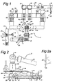
- Fig. 1 shows a highly diagrammatic plan view of a line for handling so-called unbroken board sheets. From the start (at 3) to the end (at 19), the structure and operation of the line 1 are as follows:
- the supply track 2 moves the feed pallet 3 which is loaded with unbroken sheets to an unloading point 23.
- a vertical stop wall 4 which can be placed against the feed pallet 3, or at least the stack of unbroken sheets located thereon, as indicated by double arrow 24.
- the unbroken sheets are unloaded from the feed pallet 3 one by one or preferably in partial stacks of sheets, i.e. smaller stacks containing a number of unbroken sheets are removed from the stack of sheets located on the pallet 3.
- the separate sheets or partial stacks of sheets are transferred to a first conveyor belt 6, known as the first breaking belt.
- the first breaking belt 6 By means of this first breaking belt 6, the separate sheet or the partial stack of sheets is fed to a first breaking device 7.
- the breaking device 7 (which may be of a type which is known per se from the prior art) breaks the unbroken sheet or the partial stack of sheets along the breaking lines which extend transversely to the breaking belt 6. Downstream of the first breaking device 7, the partially broken, so-called unbroken board sheet or the partially broken partial stack of sheets is transferred, at a corner transfer station 8, without its orientation being changed, to a second conveyor belt, known as the second breaking belt.
- the second breaking belt 9 guides the partially broken unbroken sheet or the partially broken partial stack of sheets through a second breaking device 10, which may operate in the same way as the first breaking device 7.
- the second breaking device 10 breaks the partially unbroken sheet or the partially broken partial stack of sheets along the second breaking lines which are at right angles to the first breaking lines. Downstream of the second breaking device 10, this results in fully separated blanks or in fully separated partial stacks of blanks.
- the separated blanks or partial stacks of blanks can be transferred to a left-hand conveyor system (24) or a right-hand conveyor system (25). This transfer may take place on the basis of the location where the separated blanks or partial stacks of blanks arrive (i.e.
- anything arriving on the right is transferred to the right-hand conveyor system 25 and anything arriving on the left is transferred to the left-hand conveyor system 24), but may also be effected with the aid of a camera system, in which case the camera system determines the shape and/or colour and, on the basis of this, regulates a control means (to the right or left), or alternatively on the basis of a preset order/direction.
- a counting unit/system 80 To the left and right of station 11 there is a counting unit/system 80, which counts the exact number of separated blanks per partial stack of sheets.
- the left-hand and right-hand conveyor systems 24 and 25 are both provided with a turning device 13 which, if appropriate as a function of an orientation of the separated blank or partial stack of blanks which is established by a camera system 12 or other type of sensor, places the separated blank or partial stack of blanks in a predetermined, desired orientation.
- the separated blanks or partial stacks of blanks are conveyed onwards to a so-called layer former, which forms a layer 30 containing a number of stacks of separated blanks, in order to allow this layer then to be transferred, by means of a stacker, to a removal pallet 21 which has been supplied via a pallet feed 16 and onto which a number of layers 30 formed in the layer former 14 are placed.
- a removal pallet 21 When a removal pallet 21 has been stacked completely full, it is removed to a turning station 18, where the fully stacked removal pallet 22 is oriented in order then to be removed, as a fully stacked removal pallet 22, to a distribution area 19 or elsewhere. Before removal pallet 22 is removed to the distribution area 19 or elsewhere, a top sheet or pallet top can be placed on the fully stacked removal pallet 22 by means of an automatic system 81.
- FIGs 2, 3 and 5 diagrammatically depict the gripper 5 according to the invention.
- the gripper comprises an arm 50, which is arranged on a fixedly positioned manipulator 51 (Fig. 1) in such a manner that it can pivot about a vertical and a horizontal axis.
- the gripper frame 33 is attached to the end of the arm 50 via a horizontal hinge 31 on which there is an extendable/retractable piston/cylinder unit 32.
- a pressure-exerting member 34 which can be extended and retracted (cf. double arrow) and, during use, can exert pressure on the top of the top unbroken board sheets to be picked up, is attached to the gripper frame 33.
- an extendable/retractable unit 37, 38 such as a spring unit or piston-cylinder unit, which is arranged at an angle and can move to and fro in the direction of the inclined double arrow, is attached to the gripper frame 33.
- a foot 39 is attached to the free end of the extendable/retractable unit 37, 38.
- the extendable/retractable unit 37, 38 bears a vertical plate-like member 52 with, on its bottom side, a lip 35 which projects to the left (in accordance with Figs. 2 and 5) and, above this lip 35, a series of ribs 36 (each rib of which extends substantially horizontally), as shown in more detail in Fig. 2a.
- a guide rail 44 on which a block 43 runs, is provided on the gripper support 33.
- This block 43 is attached to the tooth support 42.
- Four teeth cf. in particular Fig. 3
- the inner teeth 41 can be adjusted in the transverse direction before or, if appropriate also during or after, insertion beneath a sheet.
- the outer teeth 40 as indicated by a double arrow, can likewise be displaced transversely to their longitudinal direction, along a guide, before or, if appropriate also during or after, insertion beneath a sheet, in order for it to be possible to adjust the distance between adjacent teeth.
- the outer teeth 40 are mounted on the tooth carrier 42 by means of a transverse guide 42.
- the inner teeth 41 are mounted on the tooth support 42 by means of a transverse guide 46.
- the teeth 40 and 41 can preferably be adjusted independently of one another. If appropriate, the inner teeth 41 can be fixed once they have been adjusted.
- Fig. 5a shows the run-up phase of this operation
- Fig. 5b shows the phase in which the lip 35 has been pushed just under the said bottom sheet of the said partial stack of sheets to be picked up.
- the ribs 36 help to improve the engagement on the partial stack of sheets to be picked up, the effect of which will become clearer still in Fig. 5c.
- the stop wall 4 (Fig.
- the teeth 40, 41 will then arrive at the stack of sheets and will be able to push into the enlarged gap which has formed on either side of the foot 39 as a result of the partial stack of sheets which is to be picked up having been lifted further by means of foot 39.
- the ribs 36 play an important role. This is because the ribs 36 provide an additional point of engagement, on which unbroken sheets which are located at a relatively high level are supported when the lip 35 engages beneath the bottom unbroken sheet of the partial stack of sheets which is to be picked up.
- pressure-exerting member 34 moves downwards and exerts pressure on the top of the partial stack of sheets to be picked up, and the partial stack of sheets to be picked up can be handled by means of the gripper and deposited, for example, on the first breaking belt 6 (Fig. 1).
- the adjustability of the teeth 41, 40 transversely with respect to the longitudinal direction is of great importance.
- the positioning of the teeth 40, 41 with respect to one another has to be adjusted as a function of the unbroken sheets to be handled in such a manner that there is no significant overhang at the outer sides (i.e. outside the outer teeth 40), and sagging between the outer teeth 40 is also prevented.
- the procedure will be for the positioning of the teeth 40, 41 with respect to one another to be stored in a computer or other type of storage medium for a number of types of unbroken sheet which are to be handled and for the correct type of unbroken sheet to be input by means of input means each time the type of unbroken sheet is changed, so that a control unit can ensure that the positioning of the teeth 40, 41 can be adjusted correctly. Should a new type of unbroken sheet to be handled arise, the settings for the teeth 40, 41 will be determined and will also be input and stored in the storage means. All this may be implemented by means of a central control system.
- the central control system can also store data relating, for example, to the colour and shape of the various blanks and unbroken sheets. This data can then be utilized to control the breaking devices 7 and 10 and also to assist the counting member 80 and any camera system provided at 11.
- This control system can also store data relating to the desired orientation of separated blanks with a view to controlling the turning devices 13.
- the control system can hold the data for a large number of types of unbroken sheets and blanks produced therefrom, and then all the components of the overall system can be adjusted to the appropriate type of unbroken sheet to be handled in each case by means of input means.
- Fig. 4 provides further illustration, showing a plan view of an example of an unbroken sheet.
- the unbroken sheet shown in Fig. 4 contains two different types of blanks, namely three blanks 61 and three blanks 62, from which the bottom part and the lid part, respectively, of a box can be produced.
- Adjacent blanks 61 are connected via breaking lines 63.
- Adjacent blanks 62 are connected via breaking lines 64 which are not aligned with the breaking lines 63, although if appropriate this is quite possible.
- the blanks 61, 62 are in each case connected via short breaking lines 65.
Description
- The invention relates to a method for separating blanks for cardboard boxes, in particular packaging boxes, from unbroken board sheets which each comprise a number of blanks which are connected to one another along breaking lines, in which method:
- in a step c), the unbroken sheets are broken into separated blanks; and
- in a step d) the separated blanks are preferably formed into stacks of blanks; and
- in a step e) these stacks of blanks are packaged, if appropriate.
-
- For the production of packaging boxes from corrugated board, the procedure is generally as follows. A starting sheet of corrugated board is, where necessary, provided with text and/or pictures (by printing or processing preprinted sheets). Preferably after this, but if appropriate before, a number of blanks, which are still connected to one another along breaking lines, are formed in the starting sheet. Such a sheet having a number of blanks which are connected to one another along breaking lines is known as "an unbroken sheet". In line with this process, each unbroken sheet is broken into separate blanks. This breaking may take place manually or, if appropriate, mechanically. Breaking is extremely easy, since the breaking lines are already such that the blanks can break free along the breaking lines if the unbroken sheet is picked up. The separated blanks are then manually or mechanically formed into stacks of blanks, which stacks of blanks are then generally packaged further, for example by wrapping a sheet around them, by winding a wire around them or by placing the stacks of blanks in an outer box. All this generally takes place at the premises of the supplier, also known as the "packaging producer", of the packaging box. The stacks of blanks are then transported to the location where the blanks are formed into boxes, which are then filled.
- In the case of solid board, the packaging producer operates somewhat differently. In the case of solid board, the blanks are generally formed directly from the starting sheet by punching. In this case, therefore, there is no formation of a so-called unbroken sheet which is broken into separate blanks in a subsequent breaking step (although this method does exist). Therefore, the separation of the blanks takes place directly during punching. Afterwards, the blanks are again formed into stacks of blanks which can be packaged and made available to the purchaser.
- The drawback of the method outlined above is that the packaging producer, as the purchaser's supplier, must have a large production capacity in order to be able to supply blanks sufficiently quickly at all times in particular in the event of highly fluctuating demand from the purchaser. Such a situation arises, for example, with boxes for packaging seasonal products, such as ice creams. Ice creams are typically products which are produced and therefore also packaged primarily in the summer season and for which, in addition, demand is very strongly influenced by the weather at the time. If the packaging producer, as supplier, then wants to be able to keep up with a high demand, he must either have or have in reserve sufficiently great production capacity or must have sufficient stocks of stacks containing separate blanks. Apart from the fact that these stocks result in a high level of tied-up capital, a relatively high storage capacity is also required. It will be clear that such problems are also very likely for products other than ice creams. The second drawback of the current method is that the process steps may influence one another. For example, a fault during the formation of stacks of blanks may have a direct effect on the stamping and printing process.
- The object of the present invention is to provide a method for separating blanks for cardboard boxes which, inter alia, offers a solution to the above problems.
- According to the invention, this object is achieved by, in a step a) (before step c), stacking the unbroken sheets to form a stack of sheets. As may be clear, in this context a stack of sheets is understood to mean a stack of unbroken sheets. Apart from the above-described problems with being able to quickly satisfy fluctuating demand, this stacking to form a stack of sheets offers the advantage that, if it is desired for the separation or, if appropriate, the use of the blanks to take place in line with the operation of forming blanks from starting sheets, the separation step can be made independent of the preceding forming step, by forming a buffer, i.e. the stack of sheets. This means that, in the event of stagnation in the separation process or a subsequent process, the previous forming process can continue to operate, or in the event of stagnation in the forming process the subsequent separating process or further process can continue.
- It should be clear that the method according to the invention can be used both for boxes, or more correctly blanks, made from corrugated board and for boxes or blanks made from solid board. In the latter case, the punching device will have to be suitable for the production of unbroken board sheets with blanks which are connected to one another via breaking lines. The production of pieces of solid board which are connected to one another via breaking lines is not per se anything special and is already known from the prior art.
- The formation of one or more stacks of sheets not only makes it possible to form a buffer, but also, instead or in addition, also makes it possible to render the separation process more efficient, by, in step c), breaking the stack of sheets or a partial stack of sheets into separated partial stacks of blanks. It is thus possible for the entire stack of sheets to undergo the breaking step all at once, instead of sheet by sheet, which may then result in correspondingly high stacks of separated blanks, referred to as partial stacks of blanks. It is also conceivable for part, known as a partial stack of sheets, to be removed from the stack of sheets and subjected to the breaking process all at once. In this case too, the breaking of a partial stack of sheets may then result in correspondingly high separated partial stacks of blanks. If the entire stack of sheets is subjected to a breaking step all at once, in line with the forming process which precedes the breaking process, the abovementioned buffer effect will be, at least partially, lost, unless a plurality of successive stacks of blanks are ready. However, partial stacks of blanks are still easier to handle than each blank separately. If in each case a partial stack of sheets from a stack of sheets is subjected to the breaking process (step a)), the remaining stack of sheets will continue to act as a buffer.
- According to the invention, forming stacks of unbroken sheets not only makes it possible, in an in-line situation, to make the operation of step c) less dependent on the preceding forming process, but also makes it possible to provide a solution to the abovementioned problems by decoupling the separation process from the forming process (in which unbroken board sheets are formed from starting sheets) entirely. This is because, in the first instance, it is possible to form stacks of unbroken board sheets (which each in turn comprise a number of blanks connected to one another along breaking lines), and to hold these stacks in stock for a longer or shorter time. Stock stacks of this nature take up less space than stacks of blanks which have already been separated and, moreover, tie up less capital. Then, once the purchaser has requested stacks of separated blanks, one or more stacks of unbroken board sheets which have previously been held in stock can be removed from storage and converted into stacks of blanks containing separated blanks. This essentially means that, according to a further embodiment of the method according to the invention, after step a) and before step e), in a step b), an unbroken sheet or preferably a partial stack of unbroken sheets is removed from the stack of sheets and subjected to step c). In this case, step b) can, according to the invention, be carried out in an advantageous manner, preferably automatically, by firstly inserting a lip beneath the sheet which is to be removed or the bottom sheet of the partial stack of sheets which is to be removed, preferably approximately in the centre of a longitudinal or transverse side of the stack of sheets, and by lifting the said sheet or the said bottom sheet of the partial stack of sheets, in such a manner that a gap is formed on either side of the lip, and by inserting a first tooth into the said gap on either side of the lip and using these first teeth to increase the length of the gap, measured from the lip, on either side of the lip, by inserting in each case a second tooth into the gap on the outer sides, remote from one another, of the first teeth, which has been enlarged in this way, and by fitting the teeth all the way through beneath the said sheet or the said partial stack of sheets. In this way, the unbroken sheets can be carefully removed from the stack of sheets without prematurely breaking along the breaking line. This has the advantage that it is consequently possible to feed the unbroken board sheets accurately and in a predetermined manner to a breaking process, preferably an automated breaking process. This is of benefit to the reliability and speed of the entire process.
- According to an advantageous embodiment of the invention, the board sheets may comprise blanks of two or more different types and, after step c) and before any step d), the blanks are sorted according to type and, in any such step d), stacks of blanks are formed for each type containing blanks of the said type, and if appropriate these stacks of blanks are packaged. It thus becomes possible for the unbroken sheets, with regard to the space which they take up, to be divided as efficiently as possible and, if various types of blanks are arranged on these sheets, for these various types of blanks still to be stacked and delivered in separate stacks for each type.
- According to the invention, the breaking operation can advantageously be brought about if, in step c), the following partial steps are carried out:
- c1) the unbroken sheets are conveyed in a first direction with respect to the said sheets, and the breaking lines which are at right angles to the said first direction are broken in order to form unbroken subsheets each containing a single row, which extends transversely to the first direction, of blanks which are connected to one another along breaking lines; and
- c2) the subsheets obtained in step c1) are conveyed in a second direction with respect to the said sheets, which second direction forms an angle with the first direction, and the breaking lines which are at right angles to this second direction are broken in order to form the separated blanks.
-
- A breaking method of this nature can in particular be automated very successfully. The unbroken sheets may each be conveyed separately or in so-called partial stacks of sheets or ordinary stacks of sheets in a first direction by means of a first conveyor belt, the breaking lines which are at right angles to this first conveying direction then being relatively easy to break using breaking installations which are known per se, such as a so-called "bundle breaker", which operates according to the principle that bundles which are still connected are broken, the two sides next to the breaking line being clamped and separated from one another by means of a breaking operation, but also by means of other types of breaking installations. After step c1), the subsheets obtained in this way can be rotated with respect to the conveyor belt by means of a turning device, for example, and can then be conveyed onwards, by the same or a different conveyor belt, in line with the original conveying direction in order then to be subjected to a second breaking operation in which the remaining breaking lines which are at right angles to the second conveying direction are broken. However, it is also conceivable to use a first conveyor belt and a second conveyor belt which is at right angles to the first conveyor belt and to transfer the subsheets obtained in step c1) to the second conveyor belt without changing their orientation (or, if appropriate, while changing their orientation) and to break the remaining breaking lines on this second conveyor belt.
- To obtain stacks of blanks in which all the blanks are oriented in the same direction, according to the invention it is advantageous if, before any step d), the orientation of the separated blanks is determined and if this orientation is adjusted to a predetermined, desired orientation if the determined orientation deviates from the desired orientation. The desired orientation will in this case be the orientation in which the blank is fed to the stacking means or, if appropriate, even the orientation in which the blank is to be stacked on the stack of blanks.
- The invention also relates to a device for carrying out the method according to the invention. The device for carrying out the method according to the invention comprises the features in
claim 7. - The device for carrying out the method according to the invention comprises a gripper for removing an unbroken sheet or a partial stack of unbroken sheets from a stack of unbroken board sheets. This gripper, which independently also forms part of the invention, comprises the features in claim 11. A gripper having a separator comprising a safety pin to the inserted between a pile of sheets and a batch is disclosed in document US-A-5 242 262. Further, for removal of the batch, the gripper cooperates with a conveyor system. The lateral distance between adjacent teeth is preferably adjustable. In order to make the gripper suitable in particular for picking up a partial stack of sheets, a vertical row of tooth ribs which run horizontally transversely with respect to the first and second teeth is provided above the lip. The correct positioning of a partial stack of sheets which is to be picked up can be maintained better by means of tooth ribs of this nature. The tooth ribs advantageously have a horizontal top surface (on which the edge of the bottom surface of a sheet can be supported) and a bottom surface which tapers at an angle towards the free end of the tooth ribs.
- The device for carrying out the method according to the invention furthermore preferably comprises a first conveyor and a second conveyor which is at an angle with respect to the first conveyor, a first breaking device which carries out breaking at right angles to the conveying direction of the first conveyor, and a second breaking device which carries out breaking at right angles to the conveying direction of the second conveyor.
- The invention will be explained in more detail below with reference to an exemplary embodiment which is illustrated in the drawing, in which:
- Fig. 1 shows a highly diagrammatic plan view of a device according to the invention for carrying out the method according to the invention;
- Fig. 2 shows a diagrammatic side view of a gripper according to the invention;
- Fig. 3 shows a highly diagrammatic plan view of the gripper shown in Fig. 2, substantially illustrating its gripper members;
- Fig. 4 shows a diagrammatic plan view of an example of a so-called unbroken sheet containing six blanks; and
- Fig. 5, divided into Figs. 5a to 5d, diagrammatically depicts the way in which the gripper according to the invention operates.
-
- Fig. 1 shows a highly diagrammatic plan view of a line for handling so-called unbroken board sheets. From the start (at 3) to the end (at 19), the structure and operation of the
line 1 are as follows: - 3 represents a supply pallet which is loaded with a stack of unbroken sheets (not shown) on a
supply track 2. Thesupply track 2 moves thefeed pallet 3 which is loaded with unbroken sheets to anunloading point 23. At theunloading point 23, there is a vertical stop wall 4 which can be placed against thefeed pallet 3, or at least the stack of unbroken sheets located thereon, as indicated bydouble arrow 24. By means of agripper 5, the unbroken sheets are unloaded from thefeed pallet 3 one by one or preferably in partial stacks of sheets, i.e. smaller stacks containing a number of unbroken sheets are removed from the stack of sheets located on thepallet 3. By means of the gripper 5 (which will be explained in more detail below with reference to Figures 2, 3 and 5), the separate sheets or partial stacks of sheets are transferred to a first conveyor belt 6, known as the first breaking belt. By means of this first breaking belt 6, the separate sheet or the partial stack of sheets is fed to afirst breaking device 7. The breaking device 7 (which may be of a type which is known per se from the prior art) breaks the unbroken sheet or the partial stack of sheets along the breaking lines which extend transversely to the breaking belt 6. Downstream of thefirst breaking device 7, the partially broken, so-called unbroken board sheet or the partially broken partial stack of sheets is transferred, at a corner transfer station 8, without its orientation being changed, to a second conveyor belt, known as the second breaking belt. The second breaking belt 9 guides the partially broken unbroken sheet or the partially broken partial stack of sheets through asecond breaking device 10, which may operate in the same way as thefirst breaking device 7. Thesecond breaking device 10 breaks the partially unbroken sheet or the partially broken partial stack of sheets along the second breaking lines which are at right angles to the first breaking lines. Downstream of thesecond breaking device 10, this results in fully separated blanks or in fully separated partial stacks of blanks. When they reach station 11, the separated blanks or partial stacks of blanks can be transferred to a left-hand conveyor system (24) or a right-hand conveyor system (25). This transfer may take place on the basis of the location where the separated blanks or partial stacks of blanks arrive (i.e. anything arriving on the right is transferred to the right-hand conveyor system 25 and anything arriving on the left is transferred to the left-hand conveyor system 24), but may also be effected with the aid of a camera system, in which case the camera system determines the shape and/or colour and, on the basis of this, regulates a control means (to the right or left), or alternatively on the basis of a preset order/direction. To the left and right of station 11 there is a counting unit/system 80, which counts the exact number of separated blanks per partial stack of sheets. The left-hand and right-hand conveyor systems 24 and 25 are both provided with aturning device 13 which, if appropriate as a function of an orientation of the separated blank or partial stack of blanks which is established by acamera system 12 or other type of sensor, places the separated blank or partial stack of blanks in a predetermined, desired orientation. The separated blanks or partial stacks of blanks are conveyed onwards to a so-called layer former, which forms alayer 30 containing a number of stacks of separated blanks, in order to allow this layer then to be transferred, by means of a stacker, to aremoval pallet 21 which has been supplied via a pallet feed 16 and onto which a number oflayers 30 formed in the layer former 14 are placed. When aremoval pallet 21 has been stacked completely full, it is removed to a turningstation 18, where the fully stackedremoval pallet 22 is oriented in order then to be removed, as a fully stackedremoval pallet 22, to adistribution area 19 or elsewhere. Beforeremoval pallet 22 is removed to thedistribution area 19 or elsewhere, a top sheet or pallet top can be placed on the fully stackedremoval pallet 22 by means of anautomatic system 81. - Figures 2, 3 and 5 diagrammatically depict the
gripper 5 according to the invention. The gripper comprises anarm 50, which is arranged on a fixedly positioned manipulator 51 (Fig. 1) in such a manner that it can pivot about a vertical and a horizontal axis. Thegripper frame 33 is attached to the end of thearm 50 via ahorizontal hinge 31 on which there is an extendable/retractable piston/cylinder unit 32. A pressure-exertingmember 34, which can be extended and retracted (cf. double arrow) and, during use, can exert pressure on the top of the top unbroken board sheets to be picked up, is attached to thegripper frame 33. Furthermore, an extendable/retractable unit gripper frame 33. Afoot 39 is attached to the free end of the extendable/retractable unit retractable unit like member 52 with, on its bottom side, alip 35 which projects to the left (in accordance with Figs. 2 and 5) and, above thislip 35, a series of ribs 36 (each rib of which extends substantially horizontally), as shown in more detail in Fig. 2a. Furthermore, aguide rail 44, on which ablock 43 runs, is provided on thegripper support 33. Thisblock 43 is attached to thetooth support 42. Four teeth (cf. in particular Fig. 3), namely twoouter teeth 40, the so-called second teeth, and twoinner teeth 41, also referred to as first teeth, are attached to thetooth support 42. As indicated by the double arrow, theinner teeth 41 can be adjusted in the transverse direction before or, if appropriate also during or after, insertion beneath a sheet. Theouter teeth 40, as indicated by a double arrow, can likewise be displaced transversely to their longitudinal direction, along a guide, before or, if appropriate also during or after, insertion beneath a sheet, in order for it to be possible to adjust the distance between adjacent teeth. For this purpose, theouter teeth 40 are mounted on thetooth carrier 42 by means of atransverse guide 42. For this purpose, theinner teeth 41 are mounted on thetooth support 42 by means of atransverse guide 46. Theteeth inner teeth 41 can be fixed once they have been adjusted. - The way in which the
gripper 5 operates can be explained as follows with reference in particular to Figs. 5a, 5d: - When the gripper has been moved into the gripping position (solid lines in Fig. 1), the plate-
like member 52 is placed against the stack of unbroken sheets in such a manner that thethin lip 35 pushes in precisely beneath the bottom sheet of the partial stack of sheets to be picked up. Fig. 5a shows the run-up phase of this operation, Fig. 5b shows the phase in which thelip 35 has been pushed just under the said bottom sheet of the said partial stack of sheets to be picked up. In the process, theribs 36 help to improve the engagement on the partial stack of sheets to be picked up, the effect of which will become clearer still in Fig. 5c. The stop wall 4 (Fig. 1) in the process prevents the partial stack-of sheets which is to be picked up being pushed off the main stack of sheets. Then, theentire support frame 33, with thetooth carrier 42 for the time being held immovably with respect thereto, is displaced to the left (Fig. 5c). The plate-like member 52 above thefoot 39 will during this operation, as seen in the horizontal direction, remain in the same place but, as seen in the vertical direction, will move upwards, as a result of the extendable/retractable unit 37/38 being retracted along the top surface, which runs upwards at an angle, of thefoot 39. In the process, foot 39 will be able to push into the gap which has been formed as a result of the partial stack of sheets which is to be picked up having been lifted by means oflip 35. Theteeth foot 39 as a result of the partial stack of sheets which is to be picked up having been lifted further by means offoot 39. Particularly during the initial lifting by thelip 35, theribs 36 play an important role. This is because theribs 36 provide an additional point of engagement, on which unbroken sheets which are located at a relatively high level are supported when thelip 35 engages beneath the bottom unbroken sheet of the partial stack of sheets which is to be picked up. Consequently, the load on thelip 35 will be partially relieved and the partial stack of sheets which is to be picked up will be prevented from sliding downwards along thelip 35 under its own weight, which would impede or prevent the formation of theinitial gap 46. The operation of pushing theteeth rollers 47 at least at the front ends of the teeth and, if appropriate, additional rollers 47 (not shown) along the top surfaces of the teeth. As soon as theteeth member 34 moves downwards and exerts pressure on the top of the partial stack of sheets to be picked up, and the partial stack of sheets to be picked up can be handled by means of the gripper and deposited, for example, on the first breaking belt 6 (Fig. 1). - In view of the fragility of the unbroken sheets, in the sense that these unbroken sheets can very easily break spontaneously along their breaking lines into separate blanks, the adjustability of the
teeth teeth outer teeth 40 is also prevented. In practice, the procedure will be for the positioning of theteeth teeth teeth - The central control system can also store data relating, for example, to the colour and shape of the various blanks and unbroken sheets. This data can then be utilized to control the
breaking devices member 80 and any camera system provided at 11. This control system can also store data relating to the desired orientation of separated blanks with a view to controlling theturning devices 13. The control system can hold the data for a large number of types of unbroken sheets and blanks produced therefrom, and then all the components of the overall system can be adjusted to the appropriate type of unbroken sheet to be handled in each case by means of input means. - Fig. 4 provides further illustration, showing a plan view of an example of an unbroken sheet. The unbroken sheet shown in Fig. 4 contains two different types of blanks, namely three
blanks 61 and threeblanks 62, from which the bottom part and the lid part, respectively, of a box can be produced.Adjacent blanks 61 are connected via breaking lines 63.Adjacent blanks 62 are connected via breakinglines 64 which are not aligned with the breaking lines 63, although if appropriate this is quite possible. Theblanks
Claims (14)
- Method for separating blanks for cardboard boxes, in particular packaging boxes, from unbroken board sheets which each comprise a number of blanks which are connected to one another along breaking lines, in which method:characterized in that:in a step a) the unbroken sheets are stacked to form a stack of sheets;in a step c), after step a), the unbroken sheets are broken into separated blanks; andin a step d) the separated blanks are preferably formed into stacks of blanks;after step a) and before step c), in a step b) an unbroken sheet or preferably a partial stack of unbroken sheets is removed from the stack of sheets and subjected to step c), andthat step b) is carried out by firstly inserting a lip (35) under the sheet which is to be removed respectively the bottom sheet of the partial stack of sheets which is to be removed, preferably approximately in the centre of a longitudinal or transverse side of the stack of sheets, and, by means of the lip (35), lifting the said sheet respectively the said bottom sheet, in such a manner that a gap (46) is formed, by inserting a foot (39) into the said gap (46), the top surface of which foot (39) runs obliquely upwards in order to enlarge the gap (46) when the foot (39) is inserted into the gap (46), and by inserting a first and a second teeth (40, 41), the first tooth (41) lying between the second tooth (40) and the lip (35), into the said enlarged gap (46) on either side of the foot (39); and by fitting the teeth (40, 41) all the way through underneath the said sheet respectively the said partial stack of sheets.
- Method according to Claim 1, characterized in that first 41 and second 40 teeth are fitted into the enlarged gap (46) on either side of the foot (39), and in that the distance between adjacent first (41) and second (40) teeth is set in such a manner that an unbroken sheet which is resting on these teeth and is to be handled lies substantially flat.
- Method according to one of the preceding claims, characterized in that, in step c), the stack of sheets respectively partial stack of sheets is broken into separated partial stacks of blanks.
- Method according to one of the preceding claims, characterized in that the board sheets comprise blanks of two or more different types, and in that, after step c) and before any step d), the blanks are sorted according to type, and in any such step d), stacks of blanks are formed for each type, containing blanks of the type in question.
- Method according to one of the preceding claims, characterized in that in step c), the following partial steps are carried out:c1) the unbroken sheets are conveyed in a first direction with respect to the said sheets, and the breaking lines which are at right angles to the said first direction are broken in order to form unbroken subsheets each containing a single row, which extends transversely to the first direction, of blanks which are connected to one another along breaking lines; andc2) the subsheets obtained in step c1) are conveyed in a second direction with respect to the said sheets, which second direction forms an angle with the first direction, and the breaking lines which are at right angles to this second direction are broken in order to form the separated blanks.
- Method according to one of the preceding claims, characterized in that, before any step d), the orientation of the separated blanks is determined, and in that this orientation is changed to a predetermined, desired orientation if the determined orientation deviates from the desired orientation.
- Device for carrying out the method according to one of the preceding claims, comprising:characterized in, that the device further comprises a gripper (5) for removing an unbroken sheet or a partial stack of unbroken sheets from the stack of unbroken board sheets;sheet stacking means for stacking unbroken board sheets;breaking means (7, 10) for breaking unbroken board sheets into separated blanks; andpreferably blank-stacking means (15);
in which the gripper (5) comprises gripper control means;
in which the gripper (5) comprises a horizontal lip (35) with, on either side, a second tooth (40) and a first tooth (41) lying between the second tooth (40) and the lip (35), the first (41) and second (40) teeth being displaceable in their longitudinal directions with respect to the lip (35);
in which the gripper (5) further comprises a foot (39), which, in longitudinal direction of the first (41) and second (40) teeth, lies in line with the lip (35), in which the lip is movable upwards and the foot (39) is movable horizontally with respect to the lip (35) to pass beneath the lip; and
in which the gripper control means are designed to insert the lip (35) between two unbroken sheets, to move the lip (35) upwards so as to form a gap (46) between the said two unbroken sheets, then to push the foot (39) into the gap (46) which is formed, and next to insert the teeth (40, 41) into the enlarged gap (46) until they fit through all the way beneath the sheet or the said partial stack of sheets. - Device according to Claim 7, in which the first (41) and/or second (40) teeth can be adjusted transversely to their longitudinal directions.
- Device according to one of Claims 7-8, in which a vertical row of tooth ribs (39) which run horizontally transversely with respect to the first (41) and second (40) teeth is provided above the lip (35).
- Device according to Claim 9, in which the tooth ribs (39) have a horizontal top surface and a bottom surface which tapers at an angle towards the free end of the tooth ribs.
- Gripper for removing an unbroken sheet or a partial stack of unbroken sheets from a stack of unbroken sheets;
in which the gripper (5) comprises gripper control means;
in which the gripper (5) comprises a horizontal lip (35) with, on either side, a second tooth (40) and a first tooth (41) lying between the second tooth (40) and the lip (35), the first (41) and second (40) teeth being displaceable in their longitudinal directions with respect to the lip (35);
in which the gripper (5) further comprises a foot (39), which, in longitudinal direction of the first (41) and second (40) teeth, lies in line with the lip (35), in which the lip is movable upwards and the foot (39) is movable horizontally with respect to the lip (35) to pass beneath the lip; and
in which the gripper control means are designed to insert the lip (35) between two unbroken sheets, to move the lip (35) upwards so as to form a gap (46) between the said two unbroken sheets, then to push the foot (39) into the gap (46) which is formed, and next to insert the teeth (40, 41) into the enlarged gap (46) until they fit through all the way beneath the sheet or the said partial stack of sheets - Gripper according to claim 11, in which the first (41) and/or second (40) teeth can be adjusted transversely to their longitudinal directions.
- Gripper according to claim 10 or 11, in which a vertical row of tooth ribs (39) which run horizontally transversely with respect to the first (41) and second (40) teeth is provided above the lip (35).
- Gripper according to claim 13, in which the tooth ribs (39) have a horizontal top surface and a bottom surface which tapers at an angle towards the free end of the tooth ribs.
Priority Applications (3)
| Application Number | Priority Date | Filing Date | Title |
|---|---|---|---|
| ES00200767T ES2226698T3 (en) | 2000-03-03 | 2000-03-03 | PROCEDURE AND MACHINE TO SEPARATE PARTS IN TOSCO DE CARTON BOXES. |
| DE60013759T DE60013759T2 (en) | 2000-03-03 | 2000-03-03 | Method and apparatus for cutting cut material for cardboard boxes |
| EP00200767A EP1129843B1 (en) | 2000-03-03 | 2000-03-03 | Method and machine for separating blanks for cardboard boxes |
Applications Claiming Priority (1)
| Application Number | Priority Date | Filing Date | Title |
|---|---|---|---|
| EP00200767A EP1129843B1 (en) | 2000-03-03 | 2000-03-03 | Method and machine for separating blanks for cardboard boxes |
Publications (3)
| Publication Number | Publication Date |
|---|---|
| EP1129843A1 EP1129843A1 (en) | 2001-09-05 |
| EP1129843A8 EP1129843A8 (en) | 2002-01-16 |
| EP1129843B1 true EP1129843B1 (en) | 2004-09-15 |
Family
ID=8171147
Family Applications (1)
| Application Number | Title | Priority Date | Filing Date |
|---|---|---|---|
| EP00200767A Expired - Lifetime EP1129843B1 (en) | 2000-03-03 | 2000-03-03 | Method and machine for separating blanks for cardboard boxes |
Country Status (3)
| Country | Link |
|---|---|
| EP (1) | EP1129843B1 (en) |
| DE (1) | DE60013759T2 (en) |
| ES (1) | ES2226698T3 (en) |
Families Citing this family (7)
| Publication number | Priority date | Publication date | Assignee | Title |
|---|---|---|---|---|
| IT1395529B1 (en) * | 2009-03-06 | 2012-09-28 | Mirabella | CORRUGATED CARDBOARD SHEET LOADING SYSTEM THAT USES AN ANTHROPOMORPHIC ROBOT |
| DE102010005766B3 (en) * | 2010-01-25 | 2011-07-21 | nemac engineering GmbH, 78048 | Device for automatically removing and storing of foil stamping stacks by punching machine, has separating gripper that is arranged above support rods for removing stamping stacks |
| US8777551B1 (en) * | 2011-07-14 | 2014-07-15 | Automatan, Inc. | Robotic lifting apparatus |
| FR3043078B1 (en) * | 2015-10-30 | 2020-09-18 | C E R M E X Constructions Etudes Et Rech De Materiels Pour Lemballage Dexpedition | EXTRACTION DEVICE AND METHOD |
| CN108582230B (en) * | 2018-05-24 | 2023-08-01 | 浙江华岳包装机械有限公司 | Paper cutter with automatic waste removing function |
| DE102020113373B3 (en) * | 2020-05-18 | 2021-06-10 | Koenig & Bauer Ag | Sheet processing machine |
| DE102020113375A1 (en) * | 2020-05-18 | 2021-11-18 | Koenig & Bauer Ag | Sheet processing machine with at least one transfer transport system and method for transporting sheets in a sheet processing machine |
Family Cites Families (4)
| Publication number | Priority date | Publication date | Assignee | Title |
|---|---|---|---|---|
| CH577427A5 (en) * | 1974-10-02 | 1976-07-15 | Bobst Fils Sa J | |
| FR2514296A1 (en) * | 1981-10-12 | 1983-04-15 | Lucas Raymond | Separator for packaged pictures - has two compressing posts with detectors and two conveyor belts for reciprocation of one work post |
| CH646665A5 (en) * | 1982-05-19 | 1984-12-14 | Bobst Sa | DEVICE FOR SEPARATING FROM ONE ANOTHER THE DIFFERENT POSES OF A PACKET OF CUT SHEETS. |
| CH681886A5 (en) * | 1990-04-10 | 1993-06-15 | Bobst Sa |
-
2000
- 2000-03-03 DE DE60013759T patent/DE60013759T2/en not_active Expired - Lifetime
- 2000-03-03 EP EP00200767A patent/EP1129843B1/en not_active Expired - Lifetime
- 2000-03-03 ES ES00200767T patent/ES2226698T3/en not_active Expired - Lifetime
Also Published As
| Publication number | Publication date |
|---|---|
| ES2226698T3 (en) | 2005-04-01 |
| EP1129843A8 (en) | 2002-01-16 |
| DE60013759D1 (en) | 2004-10-21 |
| DE60013759T2 (en) | 2005-09-29 |
| EP1129843A1 (en) | 2001-09-05 |
Similar Documents
| Publication | Publication Date | Title |
|---|---|---|
| US5375967A (en) | Method and apparatus for palletizing and depalletizing | |
| US5040942A (en) | Method and apparatus for unloading blocks of blanks stacked on pallets | |
| JPH06135420A (en) | Cartoning device | |
| US4796879A (en) | Method and apparatus for stacking sheets conveyed continuously to a stacking point | |
| JP3127248B2 (en) | Palletizing system | |
| US3658220A (en) | Carton handling mechanism | |
| US5218813A (en) | Bundling device and method | |
| US5769413A (en) | Process and apparatus for automatic stack changing | |
| US5628505A (en) | Apparatus for stacking continuously arriving sheets | |
| JPH03176349A (en) | Carrying method for blank stack for pack and device therefor | |
| US5758362A (en) | Process and device for handling stacks of blanks having wrappings | |
| EP1129843B1 (en) | Method and machine for separating blanks for cardboard boxes | |
| US6146084A (en) | Automated bundling and stacking of folded corrugated boxes | |
| CN210618688U (en) | Packaging device for articles | |
| EP2432717B1 (en) | A palletizer and a method of palletizing items | |
| US20100031612A1 (en) | Apparatus for and method of packaging stackable 0bjects, in particular printed products | |
| US7418808B2 (en) | Method and apparatus for filling containers including a supporting band | |
| JPH0431974B2 (en) | ||
| US6189827B1 (en) | Process and apparatus for storing blanks | |
| EP0133945A1 (en) | Signature handling apparatus | |
| US6524058B1 (en) | Assembly and method for stacking, conveying and lifting lids | |
| KR100879640B1 (en) | Carton auto-feeding system | |
| US5507128A (en) | Tray blank magazine and infeed for packaging machine | |
| EP1050501A2 (en) | Method and unit for stacking articles, in particular paper bags or similar | |
| JP2001088954A (en) | Automatic stacked paper replacing device installed on paper sheet feeding device |
Legal Events
| Date | Code | Title | Description |
|---|---|---|---|
| PUAI | Public reference made under article 153(3) epc to a published international application that has entered the european phase |
Free format text: ORIGINAL CODE: 0009012 |
|
| AK | Designated contracting states |
Kind code of ref document: A1 Designated state(s): AT BE CH CY DE DK ES FI FR GB GR IE IT LI LU MC NL PT SE Kind code of ref document: A1 Designated state(s): DE ES FR GB |
|
| AX | Request for extension of the european patent |
Free format text: AL;LT;LV;MK;RO;SI |
|
| RAP3 | Party data changed (applicant data changed or rights of an application transferred) |
Owner name: SERCO B.V. |
|
| 17P | Request for examination filed |
Effective date: 20020305 |
|
| AKX | Designation fees paid |
Free format text: AT BE CH CY LI |
|
| RBV | Designated contracting states (corrected) |
Designated state(s): DE ES FR GB |
|
| REG | Reference to a national code |
Ref country code: DE Ref legal event code: 8566 |
|
| 17Q | First examination report despatched |
Effective date: 20030122 |
|
| GRAP | Despatch of communication of intention to grant a patent |
Free format text: ORIGINAL CODE: EPIDOSNIGR1 |
|
| GRAS | Grant fee paid |
Free format text: ORIGINAL CODE: EPIDOSNIGR3 |
|
| GRAA | (expected) grant |
Free format text: ORIGINAL CODE: 0009210 |
|
| AK | Designated contracting states |
Kind code of ref document: B1 Designated state(s): DE ES FR GB |
|
| REG | Reference to a national code |
Ref country code: GB Ref legal event code: FG4D |
|
| REF | Corresponds to: |
Ref document number: 60013759 Country of ref document: DE Date of ref document: 20041021 Kind code of ref document: P |
|
| ET | Fr: translation filed | ||
| REG | Reference to a national code |
Ref country code: ES Ref legal event code: FG2A Ref document number: 2226698 Country of ref document: ES Kind code of ref document: T3 |
|
| PLBE | No opposition filed within time limit |
Free format text: ORIGINAL CODE: 0009261 |
|
| STAA | Information on the status of an ep patent application or granted ep patent |
Free format text: STATUS: NO OPPOSITION FILED WITHIN TIME LIMIT |
|
| 26N | No opposition filed |
Effective date: 20050616 |
|
| REG | Reference to a national code |
Ref country code: FR Ref legal event code: PLFP Year of fee payment: 17 |
|
| REG | Reference to a national code |
Ref country code: DE Ref legal event code: R079 Ref document number: 60013759 Country of ref document: DE Free format text: PREVIOUS MAIN CLASS: B31B0001740000 Ipc: B31B0050740000 |
|
| REG | Reference to a national code |
Ref country code: FR Ref legal event code: PLFP Year of fee payment: 18 |
|
| REG | Reference to a national code |
Ref country code: FR Ref legal event code: PLFP Year of fee payment: 19 |
|
| PGFP | Annual fee paid to national office [announced via postgrant information from national office to epo] |
Ref country code: DE Payment date: 20190219 Year of fee payment: 20 Ref country code: GB Payment date: 20190222 Year of fee payment: 20 |
|
| PGFP | Annual fee paid to national office [announced via postgrant information from national office to epo] |
Ref country code: FR Payment date: 20190220 Year of fee payment: 20 |
|
| PGFP | Annual fee paid to national office [announced via postgrant information from national office to epo] |
Ref country code: ES Payment date: 20190401 Year of fee payment: 20 |
|
| REG | Reference to a national code |
Ref country code: DE Ref legal event code: R071 Ref document number: 60013759 Country of ref document: DE |
|
| REG | Reference to a national code |
Ref country code: GB Ref legal event code: PE20 Expiry date: 20200302 |
|
| PG25 | Lapsed in a contracting state [announced via postgrant information from national office to epo] |
Ref country code: GB Free format text: LAPSE BECAUSE OF EXPIRATION OF PROTECTION Effective date: 20200302 |
|
| REG | Reference to a national code |
Ref country code: ES Ref legal event code: FD2A Effective date: 20201203 |
|
| PG25 | Lapsed in a contracting state [announced via postgrant information from national office to epo] |
Ref country code: ES Free format text: LAPSE BECAUSE OF EXPIRATION OF PROTECTION Effective date: 20200304 |