EP3248866B1 - Giersteuerung in einem flugzeug - Google Patents
Giersteuerung in einem flugzeug Download PDFInfo
- Publication number
- EP3248866B1 EP3248866B1 EP17172520.3A EP17172520A EP3248866B1 EP 3248866 B1 EP3248866 B1 EP 3248866B1 EP 17172520 A EP17172520 A EP 17172520A EP 3248866 B1 EP3248866 B1 EP 3248866B1
- Authority
- EP
- European Patent Office
- Prior art keywords
- deflector
- aircraft
- wing
- yaw control
- control device
- Prior art date
- Legal status (The legal status is an assumption and is not a legal conclusion. Google has not performed a legal analysis and makes no representation as to the accuracy of the status listed.)
- Active
Links
- 244000261422 Lysimachia clethroides Species 0.000 claims description 5
- 230000008878 coupling Effects 0.000 claims description 4
- 238000010168 coupling process Methods 0.000 claims description 4
- 238000005859 coupling reaction Methods 0.000 claims description 4
- 239000002131 composite material Substances 0.000 claims description 3
- 239000007769 metal material Substances 0.000 claims 1
- 230000008901 benefit Effects 0.000 description 16
- 230000005484 gravity Effects 0.000 description 6
- 230000004075 alteration Effects 0.000 description 4
- 230000004048 modification Effects 0.000 description 4
- 238000012986 modification Methods 0.000 description 4
- 230000009466 transformation Effects 0.000 description 4
- 238000000844 transformation Methods 0.000 description 4
- 230000002708 enhancing effect Effects 0.000 description 3
- 239000000446 fuel Substances 0.000 description 3
- 238000010586 diagram Methods 0.000 description 2
- 239000000463 material Substances 0.000 description 2
- 239000002184 metal Substances 0.000 description 2
- 230000009471 action Effects 0.000 description 1
- 230000000295 complement effect Effects 0.000 description 1
- 230000001419 dependent effect Effects 0.000 description 1
- 230000000694 effects Effects 0.000 description 1
- 230000007246 mechanism Effects 0.000 description 1
- 230000000087 stabilizing effect Effects 0.000 description 1
Images

Classifications
-
- B—PERFORMING OPERATIONS; TRANSPORTING
- B64—AIRCRAFT; AVIATION; COSMONAUTICS
- B64C—AEROPLANES; HELICOPTERS
- B64C9/00—Adjustable control surfaces or members, e.g. rudders
- B64C9/34—Adjustable control surfaces or members, e.g. rudders collapsing or retracting against or within other surfaces or other members
-
- B—PERFORMING OPERATIONS; TRANSPORTING
- B64—AIRCRAFT; AVIATION; COSMONAUTICS
- B64C—AEROPLANES; HELICOPTERS
- B64C13/00—Control systems or transmitting systems for actuating flying-control surfaces, lift-increasing flaps, air brakes, or spoilers
- B64C13/24—Transmitting means
- B64C13/26—Transmitting means without power amplification or where power amplification is irrelevant
- B64C13/28—Transmitting means without power amplification or where power amplification is irrelevant mechanical
- B64C13/30—Transmitting means without power amplification or where power amplification is irrelevant mechanical using cable, chain, or rod mechanisms
-
- B—PERFORMING OPERATIONS; TRANSPORTING
- B64—AIRCRAFT; AVIATION; COSMONAUTICS
- B64C—AEROPLANES; HELICOPTERS
- B64C5/00—Stabilising surfaces
- B64C5/08—Stabilising surfaces mounted on, or supported by, wings
-
- B—PERFORMING OPERATIONS; TRANSPORTING
- B64—AIRCRAFT; AVIATION; COSMONAUTICS
- B64C—AEROPLANES; HELICOPTERS
- B64C5/00—Stabilising surfaces
- B64C5/10—Stabilising surfaces adjustable
-
- B—PERFORMING OPERATIONS; TRANSPORTING
- B64—AIRCRAFT; AVIATION; COSMONAUTICS
- B64C—AEROPLANES; HELICOPTERS
- B64C9/00—Adjustable control surfaces or members, e.g. rudders
- B64C9/02—Mounting or supporting thereof
-
- B—PERFORMING OPERATIONS; TRANSPORTING
- B64—AIRCRAFT; AVIATION; COSMONAUTICS
- B64C—AEROPLANES; HELICOPTERS
- B64C9/00—Adjustable control surfaces or members, e.g. rudders
- B64C9/12—Adjustable control surfaces or members, e.g. rudders surfaces of different type or function being simultaneously adjusted
-
- B—PERFORMING OPERATIONS; TRANSPORTING
- B64—AIRCRAFT; AVIATION; COSMONAUTICS
- B64C—AEROPLANES; HELICOPTERS
- B64C9/00—Adjustable control surfaces or members, e.g. rudders
- B64C9/32—Air braking surfaces
- B64C9/323—Air braking surfaces associated with wings
-
- Y—GENERAL TAGGING OF NEW TECHNOLOGICAL DEVELOPMENTS; GENERAL TAGGING OF CROSS-SECTIONAL TECHNOLOGIES SPANNING OVER SEVERAL SECTIONS OF THE IPC; TECHNICAL SUBJECTS COVERED BY FORMER USPC CROSS-REFERENCE ART COLLECTIONS [XRACs] AND DIGESTS
- Y02—TECHNOLOGIES OR APPLICATIONS FOR MITIGATION OR ADAPTATION AGAINST CLIMATE CHANGE
- Y02T—CLIMATE CHANGE MITIGATION TECHNOLOGIES RELATED TO TRANSPORTATION
- Y02T50/00—Aeronautics or air transport
- Y02T50/40—Weight reduction
Definitions
- This disclosure relates in general to aircraft control, and more particularly to yaw control in an aircraft.
- a yawing moment may be exerted on an aircraft.
- the moment may cause a side-to-side movement of the aircraft's nose. This side-to-side movement may be referred to as yaw.
- US 6,491,261 discloses a wing mounted yaw control device is disclosed.
- the wing mounted yaw control device includes a spoiler hingedly mounted on a first wing surface and a deflector hingedly mounted on a second wing surface.
- a deployment mechanism is provided to effect simultaneous deployment of the spoiler and deflector.
- US 5,895,015 discloses an automatic flap that uses on each wing two adjacent fins, one of which is smaller and is located on the middle or front of the wing, the other, which is larger, on the bottom rear of the wing, with a shaft in the common eccentric zone linking the two fins, said shaft being parallel to the axis of the wing, having the fins different resistance to the ram air, creating a rotation torque as a function of the aircraft's speed, when retracted, they are shaped so that the front or top fin adapts to the upper surface of the wing and the rear or bottom fin adapts to the lower surface so that, together with the wing, they form an aerodynamic profile, there are attachment arms between the two fins, and bands or springs to assist or complement the action of the smaller fin whose resistance is such that, at low speed, the flap remains extended
- the surfaces are mounted on a wing surface by hinges which are canted with respect to the free stream flow. In this manner, the extended deployed surfaces are given an angle of attack to the free stream flow to produce a lift force at essentially right angles to the longitudinal axis of the aircraft.
- an aircraft according to claim 1.
- Optional features of the aircraft are set out in the dependent claims.
- An aircraft may rotate about three axes due to forces exerted on the aircraft during flight. These three axes each intersect the aircraft's center of gravity and include the following: a pitch axis, a roll axis, and a yaw axis.
- the pitch axis is an axis that is perpendicular to the side of the body (e.g., a lateral axis through the aircraft's center of gravity).
- the roll axis is an axis that is parallel to the body (e.g., a longitudinal axis that runs the length of the body and intersects the aircraft's center of gravity).
- the yaw axis is an axis that is perpendicular to the top surface of the body (e.g., a vertical axis through the aircraft's center of gravity).
- An aircraft may include components to control rotation about these axes to provide stability and safety to the aircraft.
- Yaw control may allow an aircraft to counteract side forces that are exerted on the aircraft during flight. For example, an aerodynamic force, such as wind, may act on a left side of an aircraft's nose. This aerodynamic force may create a moment about the aircraft's yaw axis that could result in the aircraft rotating clockwise about the yaw axis. Without yaw control to balance the aerodynamic force, the aircraft may rotate uncontrollably.
- an aerodynamic force such as wind
- aspects of the present disclosure include an apparatus that, in one embodiment, includes a first deflector configured to couple to a shaft of a wing of an aircraft and form part of a top surface of the wing when in a first closed position, and a second deflector configured to couple to the shaft and form part of a bottom surface of the wing when in a second closed position.
- the first deflector and the second deflector may be configured to be positioned proximate to the tip of the wing.
- the first deflector and the second deflector are configured to simultaneously pivot from the closed positions to respective first and second open positions upon actuation of the shaft.
- the yaw control device is positioned proximate to the wingtip such that thicker regions of the wing may be used for fuel storage thereby maximizing the range of an aircraft.
- positioning the yaw control device proximate to the wingtip so that the yaw control device is not in front of a trailing edge control device (e.g., an elevon) in the wing may provide a primary load path that may not have to transfer loads through multiple adjacent cutouts in the wing structure.
- a smaller actuator load may be used to actuate the deflectors of the yaw control device because the deflectors are coupled to a common shaft.
- the yaw control device is positioned at a distance from the leading and trailing edges of a wing so that the leading and trailing edges are maintained as continuous edges with no breaks in the edges even when the yaw control device is in an open position, thereby enhancing the aerodynamic performance of the aircraft.
- the yaw control device is positioned at a distance from the wingtip such that the tip of the wing cannot open and close with the deflectors.
- the common shaft may be oriented at an aft-swept angle, thereby providing a side force adding to the generation of a yaw moment.
- Deflectors having an aft-swept common shaft may generate a greater yaw moment for a given surface size than a common shaft oriented normal to a longitudinal axis of the aircraft.
- the deflectors of the yaw control device may each have an approximately equal area thereby providing counter-acting hinge moments about the common shaft attached to the deflectors.
- the counter-acting hinge moments may minimize the total hinge moment that the common control actuator must overcome, thereby allowing for a smaller actuator.
- the deflectors may be opened on both left and right wings simultaneously, thereby providing a speed-brake function.
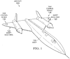
- FIGURE 1 illustrates aircraft 100 in which an example yaw control device 130 may be used
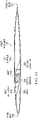
- FIGURE 2 shows an example swept back wing 120 with yaw control device 130 of FIGURE 1
- FIGURES 3A and 3B illustrate a section view of swept back wing 120 and yaw control device 130 of FIGURE 2 in a closed and open position.
- FIGURE 1 is a diagram illustrating an aircraft 100 in which an example yaw control device 130 may be used, according to certain embodiments.
- Aircraft 100 may be any type of airborne vehicle in an embodiment.
- aircraft 100 may be a tailless aircraft.
- Tailless aircraft may not have a vertical fin and/or a horizontal stabilizing structure in the aircraft's tail section in some embodiments.
- aircraft 100 may be an aircraft with a tail.
- Aircraft 100 includes a body 110, a swept back wing 120 and a yaw control device 130.
- Body 110 may be a structural component of aircraft 100 in an embodiment.
- body 110 may be a fuselage.
- body 110 may be the main structural component of an aircraft with a "flying wing" configuration.
- Body 110 may be any shape.
- body 110 may be a long hollow cylindrical tube.
- body 110 may have a slender shape to reduce drag, such as in a fighter plane.
- Body 110 is coupled to swept back wing 120.
- Swept back wing 120 may be a wing that angles rearward from root 210 in an embodiment.
- swept back wing 120 may be angled rearward in a direction from the nose of aircraft 100 towards the rear of aircraft 100 rather than at an angle perpendicular to body 110.
- Swept back wing 120 may have various sweep angles that can be measured by comparing a line from leading edge 230 to tip 220 to a perpendicular of a longitudinal axis of body 110 (such as the pitch axis).
- swept back wing 120 may have a sweep angle of twenty-five degrees.
- swept back wing 120 may have a sweep angle of forty-five degrees.
- Swept back wing 120 may be coupled to body 110 at root 210 in certain embodiments.
- Swept back wing 120 may provide a technical advantage of delaying shockwaves and aerodynamic drag of aircraft 100.
- Swept back wing 120 includes a yaw control device 130 in certain embodiments.
- Yaw control device 130 is a device that includes first deflector 250 and second deflector 260 (described below) configured to provide yaw control in aircraft 100.
- aerodynamic forces may be exerted on aircraft 100, which may cause aircraft 100 to rotate about its yaw axis.
- yaw control device 130 may be actuated such that yaw control device 130 pivots to an open position.
- One or more yaw control devices 130 are positioned on each swept back wing 120.
- each swept back wing 120 may have two yaw control devices 130.
- each yaw control device 130 may have two deflectors that are actuated by separate shafts.
- Yaw control device 130 is positioned proximate to tip 220 of swept back wing 120.
- FIGURE 2 is a bottom perspective view illustrating an example of swept back wing 120 with yaw control device 130 of FIGURE 1 , according to certain embodiments.
- Swept back wing 120 includes a root 210, a tip 220, a leading edge 230, a trailing edge 240, a first deflector 250, a second deflector 260, and distances 270, 280, and 290.
- Root 210 is a portion of swept back wing 120 that is attached to body 110.
- root 210 may represent the centerline of aircraft 100, such as in a "flying wing" configuration.
- Root 210 may be located proximal to body 110 and distal to tip 220 in an embodiment.
- Root 210 may run parallel to body 110 in certain embodiments.
- Root 210 may be positioned opposite to tip 220 in certain embodiments.
- Tip 220 of swept back wing 120 may be a portion of swept back wing 120 that forms the outermost edge of swept back wing 120 with respect to body 110. Tip 220 is distal to body 110. Tip 220 may be positioned opposite to root 210 in certain embodiments. Tip 220 may have a continuous edge in an embodiment. For example, when first deflector 250 and second deflector 260 are positioned in an open position, an edge of tip 220 may not have a break in its structure. In certain embodiments, tip 220 remains in a fixed position and does not actuate or pivot with first deflector 250 and second deflector 260. A continuous edge at tip 220 may provide improved structural stiffness and structural load paths. In addition, a continuous edge at tip 220 may provide improved aerodynamic efficiency due to the lack of gaps or edges in tip 220 associated with other tip-mounted control surfaces.
- Leading edge 230 may be the foremost edge of swept back wing 120 in an embodiment.
- Leading edge 230 is a continuous edge. When first deflector 250 and second deflector 260 are positioned in an open position, leading edge 230 is a single edge without any breaks in its structure. In certain embodiments, leading edge 230 remains in a fixed position and does not actuate or pivot with first deflector 250 and second deflector 260.
- a continuous edge along leading edge 230 may provide improved aerodynamic efficiency due to the lack of gaps or edges in leading edge 230.
- Trailing edge 240 may be the rear edge of swept back wing 120 in an embodiment. Trailing edge 240 may be opposed to leading edge 230 in an embodiment. Trailing edge 240 is a continuous edge. When first deflector 250 and second deflector 260 are positioned in an open position, trailing edge 240 is a single edge without any breaks in its structure. In certain embodiments, trailing edge 240 remains in a fixed position and does not actuate or pivot with first deflector 250 and second deflector 260. A continuous edge along trailing edge 240 may provide improved aerodynamic efficiency due to the lack of gaps or edges in trailing edge 240.
- Top surface 242 may be a surface of swept back wing 120 that is the top-most surface of swept back wing 120 in an embodiment. Top surface 242 may also be a surface from which first deflector 250 extends when actuated to an open position. Top surface 242 may be opposed to bottom surface 244 in an embodiment.
- Bottom surface 244 may be a surface of swept back wing 120 that is the bottom-most surface of swept beck wing 120 in an embodiment. Bottom surface 244 may also be a surface from which second deflector 260 extends when actuated to an open position in an embodiment. Bottom surface 244 may be opposed to top surface 242 in an embodiment.
- First deflector 250 may be a panel of swept back wing 120 that provides yaw control for aircraft 100 in an embodiment.
- First deflector 250 may be located proximate to tip 220 in an embodiment.
- first deflector 250 may be positioned at distance 290 from tip 220.
- first deflector 250 may be positioned closer to tip 220 than to root 210.
- First deflector 250 may be positioned at distance 290 from tip 220 such that tip 220 does not actuate with first deflector 250.
- First deflector 250 may be positioned distal to root 210 and body 110 in an embodiment.
- first deflector 250 may provide the ability for tip 220 to be a continuous closed structure that may have advantages of stiffness, lighter weight and improved aerodynamics.
- First deflector 250 is attached to shaft 310 (discussed below in reference to FIGURE 3A ).
- First deflector 250 is attached to shaft 310 using hinge 320.
- First deflector is actuated by shaft 310.
- first deflector 250 may be actuated by pilot control or automatically.
- First deflector 250 may be approximately the same size as second deflector 260 in an embodiment.
- first deflector 250 and second deflector 260 may have the same length and width.
- first deflector 250 and second deflector 260 may have the same area.
- first deflector 250 may be adjusted as needed to provide the best balance between control authority and minimizing actuator hinge moment.
- First deflector 250 may be any shape in an embodiment.
- First deflector 250 may be made of any material, such as a metal or a composite.
- First deflector 250 may form part of top surface 242 when positioned in a closed position.
- First deflector 250 may pivot upward from top surface 242 when shaft 310 is actuated. By pivoting upward from top surface 242, first deflector 250 may provide yaw control to aircraft 100 when pivoted on a single side of aircraft 100. When first deflector 250 is pivoted on both sides of aircraft 100, first deflector 250 may act as an air brake.
- Second deflector 260 may be a panel of swept back wing 120 that provides yaw control for aircraft 100 in an embodiment. Second deflector 260 may be located proximate to tip 220 in an embodiment. For example, second deflector 260 may be positioned at distance 290 from tip 220. In that example, second deflector 260 may be positioned closer to tip 220 than to root 210. Second deflector 260 may be positioned at distance 290 from tip 220 such that tip 220 does not actuate with second deflector 260. Second deflector 260 may be positioned distal to root 210 and body 110 in an embodiment.
- second deflector 260 may provide the ability for tip 220 to be a continuous closed structure that may have advantages of stiffness, lighter weight, and improved aerodynamics.
- Second deflector 260 is attached to shaft 310.
- Second deflector 260 is attached to shaft 310 using hinge 320.
- Second deflector 260 is actuated by shaft 310.
- second deflector 260 may be actuated by pilot control or automatically.
- Second deflector 260 may be approximately the same size as first deflector 250 in an embodiment.
- first deflector 250 and second deflector 260 may have the same length and width.
- first deflector 250 and second deflector 260 may have the same area.
- Second deflector 260 may be any shape in an embodiment. Second deflector 260 may be made of any material, such as a metal or a composite. Second deflector 260 may form part of bottom surface 244 when positioned in a closed position. Second deflector 260 may pivot downward from bottom surface 244 when shaft 310 is actuated. By pivoting downward from bottom surface 244, second deflector 260 may provide yaw control to aircraft 100 when pivoted on a single side of aircraft 100. When second deflector 260 is pivoted on both sides of aircraft 100, second deflector 260 may act as an air brake.
- Distance 270 may be a non-zero distance from trailing edge 240 to first deflector 250 and second deflector 260 in an embodiment. Distance 270 may allow trailing edge 240 to be maintained as a continuous edge when first deflector 250 and second deflector 260 are positioned in an open position.
- Distance 280 may be a non-zero distance from leading edge 230 to first deflector 250 and second deflector 260 in an embodiment. Distance 280 may allow leading edge 230 to be maintained as a continuous edge when first deflector 250 and second deflector 260 are positioned in an open position.
- Distance 290 is a non-zero distance from tip 220 to first deflector 250 and second deflector 260 in an embodiment. Distance 290 may allow tip 220 to be maintained as a continuous edge even when first deflector 250 and second deflector 260 are positioned in an open position. Distance 290 may be a distance such that first deflector 250 and second deflector 260 are positioned proximate to tip 220 and distal to root 210.
- FIGURE 3A is a section view illustrating an example of swept back wing 120 with yaw control device 130 of FIGURE 2 in a closed position, according to certain embodiments.
- FIGURE 3B is a section view illustrating an example of swept back wing 120 with yaw control device 130 of FIGURE 2 in an open position, according to certain embodiments.
- yaw control device 130 may be actuated from a closed position, as illustrated in FIGURE 3A , to an open position, as illustrated in FIGURE 3B , to provide yaw control to aircraft 100.
- swept back wing 120 may include a shaft 310 and a hinge 320 in an embodiment.
- Shaft 310 may be any type of shaft configured to couple to first deflector 250 and second deflector 260 in certain embodiments.
- Shaft 310 is coupled to first deflector 250 and second deflector 260 using hinge 320.
- Shaft 310 is positioned at a swept back angle.
- Shaft 310 is positioned at a swept back angle parallel to swept back wing 120.
- Shaft 310 may be positioned proximate to leading edge 230 in certain embodiments.
- Shaft 310 may be positioned distal to trailing edge 240 in certain embodiments.
- Shaft 310 may be configured to simultaneously actuate first deflector 250 and second deflector 260 in an embodiment.
- Hinge 320 may be any type of hinge configured to couple first deflector 250 and second deflector 260 to shaft 310 in an embodiment.
- hinge 320 may be a gooseneck hinge.
- hinge 320 may be a gooseneck hinge connected to push rod linkages.
- hinge 320 may be arranged in a butterfly valve style of arrangement.
- one embodiment may include aircraft 100 with body 110 and swept back wing 120.
- Swept back wing 120 may include yaw control device 130 with first deflector 250 and second deflector 260 each coupled to shaft 310 and positioned proximate to tip 220 of swept back wing 120.
- First deflector 250 and second deflector 260 may initially be in a closed position, as illustrated in FIGURE 3A .
- shaft 310 may actuate first deflector 250 and second deflector 260 to an open position, as illustrated in FIGURE 3B .
- first deflector 250 may be actuated upward from top surface 242 and second deflector 260 may be actuated downward from bottom surface 244.
- first deflector 250 and second deflector 260 may counteract the yaw moment exerted on aircraft 100.
- a yaw moment may be introduced via a drag force acting through a moment arm relative to the center of gravity of aircraft 100 such that first deflector 250 and second deflector 260 provide yaw control to aircraft 100.
- yaw control device 130 may be positioned proximate to tip 220 such that thicker regions of swept back wing 120 may be used for fuel storage thereby maximizing the range of aircraft 100.
- positioning yaw control device 130 proximate to tip 220 so that yaw control device 130 is not in front of a trailing edge control device (e.g., an elevon) in swept back wing 120 may provide a primary load path that may not have to transfer loads through multiple adjacent cutouts in the wing structure.
- a smaller actuator load may be used to actuate the deflectors of yaw control device 130 because the deflectors may be coupled to a common shaft 310.
- first deflector 250 and second deflector 260 By coupling first deflector 250 and second deflector 260 to a common shaft 310, the aerodynamic moment about shaft 310 may be minimized due to opposing forces from the deflectors. Additionally, separate actuators may not be required since one actuator may be used to actuate the common shaft 310. As another example, yaw control device 130 may be positioned at a distance from the leading and trailing edges of swept back wing 120 so that leading edge 230 and trailing edge 240 are maintained as continuous edges with no breaks in the edges even when yaw control device 130 is in an open position, thereby enhancing the aerodynamic performance of aircraft 100.
- Yaw control device 130 is positioned at distance 290 from tip 220 such that tip 220 of swept back wing 120 cannot open and close with the deflectors. This positioning may allow for a continuous leading edge 230 and trailing edge 240 at tip 220 of swept back wing 120, which may allow for a stiffer wing structure.
- the common shaft 310 may be oriented at an aft-swept angle, thereby providing a side force adding to the generation of a yaw moment. Deflectors having an aft-swept common shaft 310 may generate a greater yaw moment for a given surface size than a common shaft oriented normal to a longitudinal axis of aircraft 100.
- first deflector 250 and second deflector 260 of yaw control device 130 may each have an approximately equal area, thereby providing counter-acting hinge moments about the common shaft 310 attached to first deflector 250 and second deflector 260.
- the counter-acting hinge moments may minimize the total hinge moment that the common control actuator must overcome, thereby allowing for a smaller actuator.
- first deflector 250 and second deflector 260 may be opened on both left and right swept back wings 120 simultaneously, thereby providing a speed-brake function.
- second deflector 260 When second deflector 260 is pivoted on both sides of aircraft 100, second deflector 260 may act as an air brake.
- Distance 270 may be a non-zero distance from trailing edge 240 to first deflector 250 and second deflector 260 in an embodiment. Distance 270 may allow trailing edge 240 to be maintained as a continuous edge when first deflector 250 and second deflector 260 are positioned in an open position.
- Distance 280 may be a non-zero distance from leading edge 230 to first deflector 250 and second deflector 260 in an embodiment. Distance 280 may allow leading edge 230 to be maintained as a continuous edge when first deflector 250 and second deflector 260 are positioned in an open position.
- Distance 290 is a non-zero distance from tip 220 to first deflector 250 and second deflector 260 in an embodiment. Distance 290 may allow tip 220 to be maintained as a continuous edge even when first deflector 250 and second deflector 260 are positioned in an open position. Distance 290 may be a distance such that first deflector 250 and second deflector 260 are positioned proximate to tip 220 and distal to root 210.
- FIGURE 3A is a section view illustrating an example of swept back wing 120 with yaw control device 130 of FIGURE 2 in a closed position, according to certain embodiments.
- FIGURE 3B is a section view illustrating an example of swept back wing 120 with yaw control device 130 of FIGURE 2 in an open position, according to certain embodiments.
- yaw control device 130 may be actuated from a closed position, as illustrated in FIGURE 3A , to an open position, as illustrated in FIGURE 3B , to provide yaw control to aircraft 100.
- swept back wing 120 may include a shaft 310 and a hinge 320 in an embodiment.
- Shaft 310 may be any type of shaft configured to couple to first deflector 250 and second deflector 260 in certain embodiments. Shaft 310 may couple to first deflector 250 and second deflector 260 in any manner. For example, shaft 310 may couple to first deflector 250 and second deflector 260 using hinge 320. Shaft 310 may be positioned at a swept back angle in certain embodiments. For example, shaft 310 may be positioned at a swept back angle parallel to swept back wing 120. Shaft 310 may be positioned proximate to leading edge 230 in certain embodiments. Shaft 310 may be positioned distal to trailing edge 240 in certain embodiments. Shaft 310 may be configured to simultaneously actuate first deflector 250 and second deflector 260 in an embodiment.
- Hinge 320 may be any type of hinge configured to couple first deflector 250 and second deflector 260 to shaft 310 in an embodiment.
- hinge 320 may be a gooseneck hinge.
- hinge 320 may be a gooseneck hinge connected to push rod linkages.
- hinge 320 may be arranged in a butterfly valve style of arrangement.
- one embodiment may include aircraft 100 with body 110 and swept back wing 120.
- Swept back wing 120 may include yaw control device 130 with first deflector 250 and second deflector 260 each coupled to shaft 310 and positioned proximate to tip 220 of swept back wing 120.
- First deflector 250 and second deflector 260 may initially be in a closed position, as illustrated in FIGURE 3A .
- shaft 310 may actuate first deflector 250 and second deflector 260 to an open position, as illustrated in FIGURE 3B .
- first deflector 250 may be actuated upward from top surface 242 and second deflector 260 may be actuated downward from bottom surface 244.
- first deflector 250 and second deflector 260 may counteract the yaw moment exerted on aircraft 100.
- a yaw moment may be introduced via a drag force acting through a moment arm relative to the center of gravity of aircraft 100 such that first deflector 250 and second deflector 260 provide yaw control to aircraft 100.
- yaw control device 130 may be positioned proximate to tip 220 such that thicker regions of swept back wing 120 may be used for fuel storage thereby maximizing the range of aircraft 100.
- positioning yaw control device 130 proximate to tip 220 so that yaw control device 130 is not in front of a trailing edge control device (e.g., an elevon) in swept back wing 120 may provide a primary load path that may not have to transfer loads through multiple adjacent cutouts in the wing structure.
- a smaller actuator load may be used to actuate the deflectors of yaw control device 130 because the deflectors may be coupled to a common shaft 310.
- first deflector 250 and second deflector 260 By coupling first deflector 250 and second deflector 260 to a common shaft 310, the aerodynamic moment about shaft 310 may be minimized due to opposing forces from the deflectors. Additionally, separate actuators may not be required since one actuator may be used to actuate the common shaft 310. As another example, yaw control device 130 may be positioned at a distance from the leading and trailing edges of swept back wing 120 so that leading edge 230 and trailing edge 240 are maintained as continuous edges with no breaks in the edges even when yaw control device 130 is in an open position, thereby enhancing the aerodynamic performance of aircraft 100.
- yaw control device 130 may be positioned at distance 290 from tip 220 such that tip 220 of swept back wing 120 may not open and close with the deflectors. This positioning may allow for a continuous leading edge 230 and trailing edge 240 at tip 220 of swept back wing 120, which may allow for a stiffer wing structure.
- the common shaft 310 may be oriented at an aft-swept angle, thereby providing a side force adding to the generation of a yaw moment. Deflectors having an aft-swept common shaft 310 may generate a greater yaw moment for a given surface size than a common shaft oriented normal to a longitudinal axis of aircraft 100.
- first deflector 250 and second deflector 260 of yaw control device 130 may each have an approximately equal area, thereby providing counter-acting hinge moments about the common shaft 310 attached to first deflector 250 and second deflector 260.
- the counter-acting hinge moments may minimize the total hinge moment that the common control actuator must overcome, thereby allowing for a smaller actuator.
- first deflector 250 and second deflector 260 may be opened on both left and right swept back wings 120 simultaneously, thereby providing a speed-brake function.
Landscapes
- Engineering & Computer Science (AREA)
- Aviation & Aerospace Engineering (AREA)
- Mechanical Engineering (AREA)
- Automation & Control Theory (AREA)
- Braking Arrangements (AREA)
- Tires In General (AREA)
Claims (7)
- Flugzeug (100), umfassend:einen Körper (110);einen hinteren Pfeilflügel (120), der an den Körper (110) gekoppelt ist, und umfasst:eine Vorderkante;eine Hinterkante;eine obere Oberfläche (242);eine untere Oberfläche (244) gegenüber der oberen Oberfläche (242);einen Ansatz (210) am Körper (110); undeine Spitze (220), distal zum Körper (110); undeine Welle (310), die in dem Flügel (120) in einem hinteren Pfeilwinkel parallel zur Vorderkante des Flügels (120) positioniert ist; undeine Giersteuerungsvorrichtung (130), die nahe an der Spitze (220) des Flügels (120) positioniert ist, wobei die Giersteuerungsvorrichtung (130) umfassteinen ersten Abweiser (250), der, wenn in einer geschlossenen Position konfiguriert, einen Teil der oberen Oberfläche (240) des Flügels (120) bildet;einen zweiten Abweiser (260), der, wenn in einer geschlossenen Position konfiguriert, einen Teil der unteren Oberfläche (244) des Flügels (120) bildet; undein Gelenk (320), das mit dem ersten Abweiser (250), dem zweiten Abweiser (260) und der Welle (310) verbunden ist, wobei das Gelenk (320) den ersten Abweiser (250) mit der Welle (310) und den zweiten Abweiser (260) mit der Welle (310) koppelt;wobei die Giersteuerungsvorrichtung (130) in einem Abstand von der Spitze (220) positioniert ist, sodass sich die Spitze (220) mit dem ersten und zweiten Abweiser (250, 260) nicht öffnen und schließen kann;wobei die Giersteuerungsvorrichtung (130) in einem Abstand von der Vorderkante des Flügels (120) und in einem Abstand von der Hinterkante des Flügels (120) positioniert ist, sodass die Vorderkante und die Hinterkante als durchgehende Kanten ohne Unterbrechungen gehalten werden, wenn der erste und zweite Abweiser (250, 260) in jeweiligen ersten und zweiten offenen Positionen sind; undwobei der erste Abweiser (250) und der zweite Abweiser (260) konfiguriert sind, um bei Betätigung der Welle (310) gleichzeitig aus den geschlossenen Positionen in jeweilige erste und zweite offene Positionen zu schwenken.
- Flugzeug (100) nach Anspruch 1, wobei eine Länge des ersten Abweisers (250) gleich einer Länge des zweiten Abweisers (260) ist.
- Flugzeug (100) nach Anspruch 1, wobei das Gelenk (320) ein Schwanenhalsgelenk ist.
- Flugzeug (100) nach einem der Ansprüche 1 bis 3, wobei der erste Abweiser (250) und der zweite Abweiser (260) eines umfassen von:einem Metallmaterial; odereinem Verbundmaterial.
- Flugzeug (100) nach einem der Ansprüche 1 bis 4, wobei der erste Abweiser (250) konfiguriert ist, um von der oberen Oberfläche des Flügels (120) nach oben zu schwenken, und der zweite Abweiser (260) konfiguriert ist, um von der unteren Oberfläche des Flügels (120) nach unten zu schwenken.
- Flugzeug (100) nach einem vorstehenden Anspruch, wobei das Flugzeug (100) ein schwanzloses Flugzeug ist.
- Flugzeug (100) nach einem vorstehenden Anspruch, weiter umfassend eine zweite Giersteuerungsvorrichtung, die nahe der Spitze (220) des Flügels (120) und in einem Abstand von der Giersteuerungsvorrichtung (130) positioniert ist, wobei die zweite Giersteuerungsvorrichtung einen dritten Abweiser und einen vierte Abweiser umfasst.
Applications Claiming Priority (1)
| Application Number | Priority Date | Filing Date | Title |
|---|---|---|---|
| US15/166,369 US10486793B2 (en) | 2016-05-27 | 2016-05-27 | Yaw control in an aircraft |
Publications (2)
| Publication Number | Publication Date |
|---|---|
| EP3248866A1 EP3248866A1 (de) | 2017-11-29 |
| EP3248866B1 true EP3248866B1 (de) | 2022-08-24 |
Family
ID=58772464
Family Applications (1)
| Application Number | Title | Priority Date | Filing Date |
|---|---|---|---|
| EP17172520.3A Active EP3248866B1 (de) | 2016-05-27 | 2017-05-23 | Giersteuerung in einem flugzeug |
Country Status (3)
| Country | Link |
|---|---|
| US (1) | US10486793B2 (de) |
| EP (1) | EP3248866B1 (de) |
| JP (1) | JP6845746B2 (de) |
Families Citing this family (2)
| Publication number | Priority date | Publication date | Assignee | Title |
|---|---|---|---|---|
| US10967957B2 (en) * | 2016-12-20 | 2021-04-06 | The Boeing Company | Methods and apparatus to extend a leading-edge vortex of a highly-swept aircraft wing |
| CN110697024B (zh) * | 2019-10-14 | 2022-07-15 | 中国航空工业集团公司西安飞机设计研究所 | 一种飞机尾翼结构 |
Citations (1)
| Publication number | Priority date | Publication date | Assignee | Title |
|---|---|---|---|---|
| US2433649A (en) * | 1944-03-14 | 1947-12-30 | Cloyd P Clevenger | Aircraft control surfaces for yaw control |
Family Cites Families (30)
| Publication number | Priority date | Publication date | Assignee | Title |
|---|---|---|---|---|
| US1280195A (en) | 1917-07-20 | 1918-10-01 | Warren S Eaton | Aeroplane-stabilizer. |
| US1545808A (en) | 1923-02-28 | 1925-07-14 | Ajello Gaetan | Safety device for aircraft |
| US1724456A (en) | 1928-04-24 | 1929-08-13 | Louis H Crook | Aerodynamic control of airplane wings |
| US2003223A (en) * | 1933-06-17 | 1935-05-28 | William K Rose | Airplane |
| DE708447C (de) | 1936-01-31 | 1941-07-21 | Forschungsanstalt Fuer Segelfl | Sturzflugbremse |
| DE737178C (de) | 1936-02-19 | 1943-07-08 | Forschungsanstalt Fuer Segelfl | Sturzflugbremse |
| DE726413C (de) | 1936-05-13 | 1942-10-13 | Forschungsanstalt Fuer Segelfl | Sturzflugbremse |
| DE718322C (de) | 1936-07-26 | 1942-03-09 | Forschungsanstalt Fuer Segelfl | Sturzflugbremse |
| US2373089A (en) | 1940-11-02 | 1945-04-10 | Boeing Aircraft Co | Stall delaying and indicating mechanism |
| US2373088A (en) | 1940-11-02 | 1945-04-10 | Boeing Aircraft Co | Stall indicator |
| US2557829A (en) | 1947-11-07 | 1951-06-19 | Thomas B Lavelle | Aircraft control means |
| US2723091A (en) | 1951-02-01 | 1955-11-08 | Roe A V & Co Ltd | Air or dive brakes for aircraft |
| US2852211A (en) | 1956-09-21 | 1958-09-16 | Xenakis George | Airplane wing with aerodynamically actuated spoiler |
| US2987277A (en) | 1958-10-14 | 1961-06-06 | North American Aviation Inc | Aircraft control system |
| GB919793A (en) | 1961-11-14 | 1963-02-27 | Sergio Caciagli | Improvements relating to aircraft wings |
| US3107882A (en) | 1962-08-10 | 1963-10-22 | Electric Auto Lite Co | Yaw control system for vtol tilt wing aircraft |
| US3721406A (en) | 1970-12-14 | 1973-03-20 | Boeing Co | Aircraft wing airflow control system |
| US3774869A (en) * | 1972-03-07 | 1973-11-27 | K Harmon | Combined throttle spoiler actuator for aircraft |
| US4132375A (en) | 1976-01-21 | 1979-01-02 | The United States Of America As Represented By The Administrator Of The National Aeronautics And Space Administration | Vortex-lift roll-control device |
| US4391424A (en) | 1976-08-30 | 1983-07-05 | Ball Brothers | Method and structure for airfoil thrust and lift control |
| US4566657A (en) * | 1979-05-21 | 1986-01-28 | Grow Harlow B | Span loaded flying wing control |
| US4466586A (en) | 1980-03-10 | 1984-08-21 | The Boeing Company | Directional control device for aircraft |
| US4739957A (en) | 1986-05-08 | 1988-04-26 | Advanced Aerodynamic Concepts, Inc. | Strake fence flap |
| GB2237254A (en) | 1989-10-25 | 1991-05-01 | Richard Harry Barnard | Secondary lifting surfaces using separated flow |
| ES2137092B1 (es) | 1996-11-14 | 2000-08-16 | Munoz Saiz Manuel | Flap automatico. |
| US6491261B1 (en) | 2000-04-17 | 2002-12-10 | The United States Of America As Represented By The Secretary Of The Air Force | Wing mounted aircraft yaw control device |
| US7503527B1 (en) | 2004-01-22 | 2009-03-17 | Fairchild Mark D | Flight control method and apparatus to produce induced yaw |
| FR2902077B1 (fr) * | 2006-06-13 | 2009-04-24 | Airbus France Sas | Dispositif de surfaces portantes mobiles pour voilure d'aeronef |
| KR101287624B1 (ko) | 2013-02-25 | 2013-07-23 | 주식회사 네스앤텍 | 착륙이 용이한 무인비행체 |
| US9845147B2 (en) | 2013-05-01 | 2017-12-19 | Northrop Grumman Systems Corporation | Recessed lift spoiler assembly for airfoils |
-
2016
- 2016-05-27 US US15/166,369 patent/US10486793B2/en active Active
-
2017
- 2017-05-23 EP EP17172520.3A patent/EP3248866B1/de active Active
- 2017-05-29 JP JP2017105216A patent/JP6845746B2/ja active Active
Patent Citations (1)
| Publication number | Priority date | Publication date | Assignee | Title |
|---|---|---|---|---|
| US2433649A (en) * | 1944-03-14 | 1947-12-30 | Cloyd P Clevenger | Aircraft control surfaces for yaw control |
Also Published As
| Publication number | Publication date |
|---|---|
| EP3248866A1 (de) | 2017-11-29 |
| US10486793B2 (en) | 2019-11-26 |
| JP2017226408A (ja) | 2017-12-28 |
| US20170341731A1 (en) | 2017-11-30 |
| JP6845746B2 (ja) | 2021-03-24 |
Similar Documents
| Publication | Publication Date | Title |
|---|---|---|
| CN111655576B (zh) | 具有后旋翼的固定机翼飞行器 | |
| US6227487B1 (en) | Augmented wing tip drag flap | |
| US20190322354A1 (en) | Lifting surfaces and associated method | |
| CN101795939B (zh) | 斜置翼身融合飞机 | |
| US7997538B2 (en) | Aerodynamic fan control effector | |
| US5961068A (en) | Aerodynamic control effector | |
| EP1587734B1 (de) | Flugzeug mit nach vorne öffnenden und abgesenkten störklappen zur giersteuerung | |
| US6682023B2 (en) | Contiguous variable camber device | |
| US10370085B2 (en) | Body tab yaw deflector | |
| US6123296A (en) | Self-actuated flow control system | |
| US4132375A (en) | Vortex-lift roll-control device | |
| CN114026022A (zh) | 具有后旋翼和t型尾翼的固定翼飞机 | |
| US5366180A (en) | High-lift device for aircraft | |
| US20050116116A1 (en) | Wing employing leading edge flaps and winglets to achieve improved aerodynamic performance | |
| EP3248866B1 (de) | Giersteuerung in einem flugzeug | |
| CN103153783A (zh) | 用于增加飞行器的气动升力的设备和方法 | |
| US11685519B2 (en) | Wing tips and wing tip construction and design methods | |
| US3575363A (en) | Horizontal tail for aircraft | |
| CN112758305B (zh) | 变构型飞行器 | |
| EP4342789A1 (de) | Flugsteuerfläche | |
| CN118083121A (zh) | 具有后旋翼的固定机翼飞行器 | |
| Lamar | Vortex-lift roll-control device |
Legal Events
| Date | Code | Title | Description |
|---|---|---|---|
| PUAI | Public reference made under article 153(3) epc to a published international application that has entered the european phase |
Free format text: ORIGINAL CODE: 0009012 |
|
| STAA | Information on the status of an ep patent application or granted ep patent |
Free format text: STATUS: THE APPLICATION HAS BEEN PUBLISHED |
|
| AK | Designated contracting states |
Kind code of ref document: A1 Designated state(s): AL AT BE BG CH CY CZ DE DK EE ES FI FR GB GR HR HU IE IS IT LI LT LU LV MC MK MT NL NO PL PT RO RS SE SI SK SM TR |
|
| AX | Request for extension of the european patent |
Extension state: BA ME |
|
| STAA | Information on the status of an ep patent application or granted ep patent |
Free format text: STATUS: REQUEST FOR EXAMINATION WAS MADE |
|
| 17P | Request for examination filed |
Effective date: 20180305 |
|
| RBV | Designated contracting states (corrected) |
Designated state(s): AL AT BE BG CH CY CZ DE DK EE ES FI FR GB GR HR HU IE IS IT LI LT LU LV MC MK MT NL NO PL PT RO RS SE SI SK SM TR |
|
| STAA | Information on the status of an ep patent application or granted ep patent |
Free format text: STATUS: EXAMINATION IS IN PROGRESS |
|
| 17Q | First examination report despatched |
Effective date: 20190626 |
|
| STAA | Information on the status of an ep patent application or granted ep patent |
Free format text: STATUS: EXAMINATION IS IN PROGRESS |
|
| STAA | Information on the status of an ep patent application or granted ep patent |
Free format text: STATUS: EXAMINATION IS IN PROGRESS |
|
| REG | Reference to a national code |
Ref country code: DE Ref legal event code: R079 Ref document number: 602017060916 Country of ref document: DE Free format text: PREVIOUS MAIN CLASS: B64C0005080000 Ipc: B64C0013280000 |
|
| GRAP | Despatch of communication of intention to grant a patent |
Free format text: ORIGINAL CODE: EPIDOSNIGR1 |
|
| STAA | Information on the status of an ep patent application or granted ep patent |
Free format text: STATUS: GRANT OF PATENT IS INTENDED |
|
| RIC1 | Information provided on ipc code assigned before grant |
Ipc: B64C 5/10 20060101ALI20220426BHEP Ipc: B64C 9/12 20060101ALI20220426BHEP Ipc: B64C 9/32 20060101ALI20220426BHEP Ipc: B64C 5/08 20060101ALI20220426BHEP Ipc: B64C 13/30 20060101ALI20220426BHEP Ipc: B64C 13/28 20060101AFI20220426BHEP |
|
| INTG | Intention to grant announced |
Effective date: 20220520 |
|
| GRAS | Grant fee paid |
Free format text: ORIGINAL CODE: EPIDOSNIGR3 |
|
| GRAA | (expected) grant |
Free format text: ORIGINAL CODE: 0009210 |
|
| STAA | Information on the status of an ep patent application or granted ep patent |
Free format text: STATUS: THE PATENT HAS BEEN GRANTED |
|
| AK | Designated contracting states |
Kind code of ref document: B1 Designated state(s): AL AT BE BG CH CY CZ DE DK EE ES FI FR GB GR HR HU IE IS IT LI LT LU LV MC MK MT NL NO PL PT RO RS SE SI SK SM TR |
|
| REG | Reference to a national code |
Ref country code: CH Ref legal event code: EP |
|
| REG | Reference to a national code |
Ref country code: DE Ref legal event code: R096 Ref document number: 602017060916 Country of ref document: DE |
|
| REG | Reference to a national code |
Ref country code: IE Ref legal event code: FG4D |
|
| REG | Reference to a national code |
Ref country code: AT Ref legal event code: REF Ref document number: 1513492 Country of ref document: AT Kind code of ref document: T Effective date: 20220915 |
|
| REG | Reference to a national code |
Ref country code: LT Ref legal event code: MG9D |
|
| REG | Reference to a national code |
Ref country code: NL Ref legal event code: MP Effective date: 20220824 |
|
| PG25 | Lapsed in a contracting state [announced via postgrant information from national office to epo] |
Ref country code: SE Free format text: LAPSE BECAUSE OF FAILURE TO SUBMIT A TRANSLATION OF THE DESCRIPTION OR TO PAY THE FEE WITHIN THE PRESCRIBED TIME-LIMIT Effective date: 20220824 Ref country code: RS Free format text: LAPSE BECAUSE OF FAILURE TO SUBMIT A TRANSLATION OF THE DESCRIPTION OR TO PAY THE FEE WITHIN THE PRESCRIBED TIME-LIMIT Effective date: 20220824 Ref country code: PT Free format text: LAPSE BECAUSE OF FAILURE TO SUBMIT A TRANSLATION OF THE DESCRIPTION OR TO PAY THE FEE WITHIN THE PRESCRIBED TIME-LIMIT Effective date: 20221226 Ref country code: NO Free format text: LAPSE BECAUSE OF FAILURE TO SUBMIT A TRANSLATION OF THE DESCRIPTION OR TO PAY THE FEE WITHIN THE PRESCRIBED TIME-LIMIT Effective date: 20221124 Ref country code: NL Free format text: LAPSE BECAUSE OF FAILURE TO SUBMIT A TRANSLATION OF THE DESCRIPTION OR TO PAY THE FEE WITHIN THE PRESCRIBED TIME-LIMIT Effective date: 20220824 Ref country code: LV Free format text: LAPSE BECAUSE OF FAILURE TO SUBMIT A TRANSLATION OF THE DESCRIPTION OR TO PAY THE FEE WITHIN THE PRESCRIBED TIME-LIMIT Effective date: 20220824 Ref country code: LT Free format text: LAPSE BECAUSE OF FAILURE TO SUBMIT A TRANSLATION OF THE DESCRIPTION OR TO PAY THE FEE WITHIN THE PRESCRIBED TIME-LIMIT Effective date: 20220824 Ref country code: FI Free format text: LAPSE BECAUSE OF FAILURE TO SUBMIT A TRANSLATION OF THE DESCRIPTION OR TO PAY THE FEE WITHIN THE PRESCRIBED TIME-LIMIT Effective date: 20220824 Ref country code: ES Free format text: LAPSE BECAUSE OF FAILURE TO SUBMIT A TRANSLATION OF THE DESCRIPTION OR TO PAY THE FEE WITHIN THE PRESCRIBED TIME-LIMIT Effective date: 20220824 |
|
| REG | Reference to a national code |
Ref country code: AT Ref legal event code: MK05 Ref document number: 1513492 Country of ref document: AT Kind code of ref document: T Effective date: 20220824 |
|
| PG25 | Lapsed in a contracting state [announced via postgrant information from national office to epo] |
Ref country code: PL Free format text: LAPSE BECAUSE OF FAILURE TO SUBMIT A TRANSLATION OF THE DESCRIPTION OR TO PAY THE FEE WITHIN THE PRESCRIBED TIME-LIMIT Effective date: 20220824 Ref country code: IS Free format text: LAPSE BECAUSE OF FAILURE TO SUBMIT A TRANSLATION OF THE DESCRIPTION OR TO PAY THE FEE WITHIN THE PRESCRIBED TIME-LIMIT Effective date: 20221224 Ref country code: HR Free format text: LAPSE BECAUSE OF FAILURE TO SUBMIT A TRANSLATION OF THE DESCRIPTION OR TO PAY THE FEE WITHIN THE PRESCRIBED TIME-LIMIT Effective date: 20220824 Ref country code: GR Free format text: LAPSE BECAUSE OF FAILURE TO SUBMIT A TRANSLATION OF THE DESCRIPTION OR TO PAY THE FEE WITHIN THE PRESCRIBED TIME-LIMIT Effective date: 20221125 |
|
| PG25 | Lapsed in a contracting state [announced via postgrant information from national office to epo] |
Ref country code: SM Free format text: LAPSE BECAUSE OF FAILURE TO SUBMIT A TRANSLATION OF THE DESCRIPTION OR TO PAY THE FEE WITHIN THE PRESCRIBED TIME-LIMIT Effective date: 20220824 Ref country code: RO Free format text: LAPSE BECAUSE OF FAILURE TO SUBMIT A TRANSLATION OF THE DESCRIPTION OR TO PAY THE FEE WITHIN THE PRESCRIBED TIME-LIMIT Effective date: 20220824 Ref country code: DK Free format text: LAPSE BECAUSE OF FAILURE TO SUBMIT A TRANSLATION OF THE DESCRIPTION OR TO PAY THE FEE WITHIN THE PRESCRIBED TIME-LIMIT Effective date: 20220824 Ref country code: CZ Free format text: LAPSE BECAUSE OF FAILURE TO SUBMIT A TRANSLATION OF THE DESCRIPTION OR TO PAY THE FEE WITHIN THE PRESCRIBED TIME-LIMIT Effective date: 20220824 Ref country code: AT Free format text: LAPSE BECAUSE OF FAILURE TO SUBMIT A TRANSLATION OF THE DESCRIPTION OR TO PAY THE FEE WITHIN THE PRESCRIBED TIME-LIMIT Effective date: 20220824 |
|
| REG | Reference to a national code |
Ref country code: DE Ref legal event code: R097 Ref document number: 602017060916 Country of ref document: DE |
|
| PG25 | Lapsed in a contracting state [announced via postgrant information from national office to epo] |
Ref country code: SK Free format text: LAPSE BECAUSE OF FAILURE TO SUBMIT A TRANSLATION OF THE DESCRIPTION OR TO PAY THE FEE WITHIN THE PRESCRIBED TIME-LIMIT Effective date: 20220824 Ref country code: EE Free format text: LAPSE BECAUSE OF FAILURE TO SUBMIT A TRANSLATION OF THE DESCRIPTION OR TO PAY THE FEE WITHIN THE PRESCRIBED TIME-LIMIT Effective date: 20220824 |
|
| PG25 | Lapsed in a contracting state [announced via postgrant information from national office to epo] |
Ref country code: AL Free format text: LAPSE BECAUSE OF FAILURE TO SUBMIT A TRANSLATION OF THE DESCRIPTION OR TO PAY THE FEE WITHIN THE PRESCRIBED TIME-LIMIT Effective date: 20220824 |
|
| PLBE | No opposition filed within time limit |
Free format text: ORIGINAL CODE: 0009261 |
|
| STAA | Information on the status of an ep patent application or granted ep patent |
Free format text: STATUS: NO OPPOSITION FILED WITHIN TIME LIMIT |
|
| 26N | No opposition filed |
Effective date: 20230525 |
|
| P01 | Opt-out of the competence of the unified patent court (upc) registered |
Effective date: 20230705 |
|
| PG25 | Lapsed in a contracting state [announced via postgrant information from national office to epo] |
Ref country code: SI Free format text: LAPSE BECAUSE OF FAILURE TO SUBMIT A TRANSLATION OF THE DESCRIPTION OR TO PAY THE FEE WITHIN THE PRESCRIBED TIME-LIMIT Effective date: 20220824 |
|
| PGFP | Annual fee paid to national office [announced via postgrant information from national office to epo] |
Ref country code: IT Payment date: 20230720 Year of fee payment: 7 Ref country code: GB Payment date: 20230727 Year of fee payment: 7 |
|
| PGFP | Annual fee paid to national office [announced via postgrant information from national office to epo] |
Ref country code: FR Payment date: 20230725 Year of fee payment: 7 Ref country code: DE Payment date: 20230727 Year of fee payment: 7 |
|
| REG | Reference to a national code |
Ref country code: CH Ref legal event code: PL |
|
| PG25 | Lapsed in a contracting state [announced via postgrant information from national office to epo] |
Ref country code: MC Free format text: LAPSE BECAUSE OF FAILURE TO SUBMIT A TRANSLATION OF THE DESCRIPTION OR TO PAY THE FEE WITHIN THE PRESCRIBED TIME-LIMIT Effective date: 20220824 |
|
| REG | Reference to a national code |
Ref country code: BE Ref legal event code: MM Effective date: 20230531 |
|
| PG25 | Lapsed in a contracting state [announced via postgrant information from national office to epo] |
Ref country code: MC Free format text: LAPSE BECAUSE OF FAILURE TO SUBMIT A TRANSLATION OF THE DESCRIPTION OR TO PAY THE FEE WITHIN THE PRESCRIBED TIME-LIMIT Effective date: 20220824 Ref country code: LU Free format text: LAPSE BECAUSE OF NON-PAYMENT OF DUE FEES Effective date: 20230523 Ref country code: LI Free format text: LAPSE BECAUSE OF NON-PAYMENT OF DUE FEES Effective date: 20230531 Ref country code: CH Free format text: LAPSE BECAUSE OF NON-PAYMENT OF DUE FEES Effective date: 20230531 |
|
| REG | Reference to a national code |
Ref country code: IE Ref legal event code: MM4A |
|
| PG25 | Lapsed in a contracting state [announced via postgrant information from national office to epo] |
Ref country code: IE Free format text: LAPSE BECAUSE OF NON-PAYMENT OF DUE FEES Effective date: 20230523 |
|
| PG25 | Lapsed in a contracting state [announced via postgrant information from national office to epo] |
Ref country code: IE Free format text: LAPSE BECAUSE OF NON-PAYMENT OF DUE FEES Effective date: 20230523 |