EP3248794B1 - Procédé d'utilisation d'une imprimante - Google Patents
Procédé d'utilisation d'une imprimante Download PDFInfo
- Publication number
- EP3248794B1 EP3248794B1 EP17172838.9A EP17172838A EP3248794B1 EP 3248794 B1 EP3248794 B1 EP 3248794B1 EP 17172838 A EP17172838 A EP 17172838A EP 3248794 B1 EP3248794 B1 EP 3248794B1
- Authority
- EP
- European Patent Office
- Prior art keywords
- substrate
- surface energy
- thermoformable
- ink
- web
- Prior art date
- Legal status (The legal status is an assumption and is not a legal conclusion. Google has not performed a legal analysis and makes no representation as to the accuracy of the status listed.)
- Active
Links
- 238000000034 method Methods 0.000 title claims description 37
- 239000000758 substrate Substances 0.000 claims description 105
- 238000012986 modification Methods 0.000 claims description 31
- 230000004048 modification Effects 0.000 claims description 31
- 238000001723 curing Methods 0.000 claims description 22
- 230000005855 radiation Effects 0.000 claims description 17
- 238000003847 radiation curing Methods 0.000 claims description 13
- 238000009736 wetting Methods 0.000 claims description 9
- 239000005020 polyethylene terephthalate Substances 0.000 claims description 7
- 229920000139 polyethylene terephthalate Polymers 0.000 claims description 7
- -1 polyethylene terephthalate Polymers 0.000 claims description 6
- 238000000151 deposition Methods 0.000 claims description 5
- 239000004800 polyvinyl chloride Substances 0.000 claims description 4
- 229920000915 polyvinyl chloride Polymers 0.000 claims description 3
- NIXOWILDQLNWCW-UHFFFAOYSA-N acrylic acid group Chemical group C(C=C)(=O)O NIXOWILDQLNWCW-UHFFFAOYSA-N 0.000 claims description 2
- XECAHXYUAAWDEL-UHFFFAOYSA-N acrylonitrile butadiene styrene Chemical compound C=CC=C.C=CC#N.C=CC1=CC=CC=C1 XECAHXYUAAWDEL-UHFFFAOYSA-N 0.000 claims description 2
- 239000004676 acrylonitrile butadiene styrene Substances 0.000 claims description 2
- 229920000122 acrylonitrile butadiene styrene Polymers 0.000 claims description 2
- 239000004417 polycarbonate Substances 0.000 claims description 2
- 229920000515 polycarbonate Polymers 0.000 claims description 2
- 239000000976 ink Substances 0.000 description 84
- 238000003491 array Methods 0.000 description 25
- 238000003856 thermoforming Methods 0.000 description 19
- 230000008569 process Effects 0.000 description 12
- 239000000463 material Substances 0.000 description 11
- 238000004519 manufacturing process Methods 0.000 description 6
- 229920003023 plastic Polymers 0.000 description 6
- 239000004033 plastic Substances 0.000 description 6
- 238000003851 corona treatment Methods 0.000 description 5
- 230000008901 benefit Effects 0.000 description 4
- 238000010586 diagram Methods 0.000 description 4
- 230000003993 interaction Effects 0.000 description 4
- 238000005457 optimization Methods 0.000 description 4
- 230000003068 static effect Effects 0.000 description 4
- 239000003086 colorant Substances 0.000 description 3
- 230000001419 dependent effect Effects 0.000 description 3
- 238000002156 mixing Methods 0.000 description 3
- 238000004140 cleaning Methods 0.000 description 2
- 238000000576 coating method Methods 0.000 description 2
- 238000005336 cracking Methods 0.000 description 2
- 230000003247 decreasing effect Effects 0.000 description 2
- 238000006386 neutralization reaction Methods 0.000 description 2
- 238000004806 packaging method and process Methods 0.000 description 2
- 239000002245 particle Substances 0.000 description 2
- 238000009832 plasma treatment Methods 0.000 description 2
- 238000013442 quality metrics Methods 0.000 description 2
- 239000007787 solid Substances 0.000 description 2
- 238000001228 spectrum Methods 0.000 description 2
- 238000002211 ultraviolet spectrum Methods 0.000 description 2
- 240000009088 Fragaria x ananassa Species 0.000 description 1
- 239000004743 Polypropylene Substances 0.000 description 1
- 239000000853 adhesive Substances 0.000 description 1
- 230000001070 adhesive effect Effects 0.000 description 1
- 230000015572 biosynthetic process Effects 0.000 description 1
- 238000006243 chemical reaction Methods 0.000 description 1
- 238000011109 contamination Methods 0.000 description 1
- 238000005520 cutting process Methods 0.000 description 1
- 230000007547 defect Effects 0.000 description 1
- 238000001514 detection method Methods 0.000 description 1
- 238000001125 extrusion Methods 0.000 description 1
- 239000004744 fabric Substances 0.000 description 1
- 239000010408 film Substances 0.000 description 1
- 235000013305 food Nutrition 0.000 description 1
- 238000003384 imaging method Methods 0.000 description 1
- 238000009434 installation Methods 0.000 description 1
- 230000001678 irradiating effect Effects 0.000 description 1
- 239000007788 liquid Substances 0.000 description 1
- 239000003607 modifier Substances 0.000 description 1
- 230000003287 optical effect Effects 0.000 description 1
- 229920006254 polymer film Polymers 0.000 description 1
- 229920001155 polypropylene Polymers 0.000 description 1
- 239000002994 raw material Substances 0.000 description 1
- 238000004064 recycling Methods 0.000 description 1
- 239000011347 resin Substances 0.000 description 1
- 229920005989 resin Polymers 0.000 description 1
- 238000005096 rolling process Methods 0.000 description 1
- 238000000926 separation method Methods 0.000 description 1
- 235000021012 strawberries Nutrition 0.000 description 1
- 238000004381 surface treatment Methods 0.000 description 1
- 239000002699 waste material Substances 0.000 description 1
Images

Classifications
-
- B—PERFORMING OPERATIONS; TRANSPORTING
- B41—PRINTING; LINING MACHINES; TYPEWRITERS; STAMPS
- B41J—TYPEWRITERS; SELECTIVE PRINTING MECHANISMS, i.e. MECHANISMS PRINTING OTHERWISE THAN FROM A FORME; CORRECTION OF TYPOGRAPHICAL ERRORS
- B41J3/00—Typewriters or selective printing or marking mechanisms characterised by the purpose for which they are constructed
- B41J3/407—Typewriters or selective printing or marking mechanisms characterised by the purpose for which they are constructed for marking on special material
- B41J3/4075—Tape printers; Label printers
-
- B—PERFORMING OPERATIONS; TRANSPORTING
- B41—PRINTING; LINING MACHINES; TYPEWRITERS; STAMPS
- B41J—TYPEWRITERS; SELECTIVE PRINTING MECHANISMS, i.e. MECHANISMS PRINTING OTHERWISE THAN FROM A FORME; CORRECTION OF TYPOGRAPHICAL ERRORS
- B41J11/00—Devices or arrangements of selective printing mechanisms, e.g. ink-jet printers or thermal printers, for supporting or handling copy material in sheet or web form
- B41J11/0015—Devices or arrangements of selective printing mechanisms, e.g. ink-jet printers or thermal printers, for supporting or handling copy material in sheet or web form for treating before, during or after printing or for uniform coating or laminating the copy material before or after printing
- B41J11/002—Curing or drying the ink on the copy materials, e.g. by heating or irradiating
- B41J11/0021—Curing or drying the ink on the copy materials, e.g. by heating or irradiating using irradiation
- B41J11/00214—Curing or drying the ink on the copy materials, e.g. by heating or irradiating using irradiation using UV radiation
-
- B—PERFORMING OPERATIONS; TRANSPORTING
- B41—PRINTING; LINING MACHINES; TYPEWRITERS; STAMPS
- B41J—TYPEWRITERS; SELECTIVE PRINTING MECHANISMS, i.e. MECHANISMS PRINTING OTHERWISE THAN FROM A FORME; CORRECTION OF TYPOGRAPHICAL ERRORS
- B41J11/00—Devices or arrangements of selective printing mechanisms, e.g. ink-jet printers or thermal printers, for supporting or handling copy material in sheet or web form
- B41J11/0015—Devices or arrangements of selective printing mechanisms, e.g. ink-jet printers or thermal printers, for supporting or handling copy material in sheet or web form for treating before, during or after printing or for uniform coating or laminating the copy material before or after printing
- B41J11/002—Curing or drying the ink on the copy materials, e.g. by heating or irradiating
- B41J11/0021—Curing or drying the ink on the copy materials, e.g. by heating or irradiating using irradiation
- B41J11/00216—Curing or drying the ink on the copy materials, e.g. by heating or irradiating using irradiation using infrared [IR] radiation or microwaves
-
- B—PERFORMING OPERATIONS; TRANSPORTING
- B41—PRINTING; LINING MACHINES; TYPEWRITERS; STAMPS
- B41J—TYPEWRITERS; SELECTIVE PRINTING MECHANISMS, i.e. MECHANISMS PRINTING OTHERWISE THAN FROM A FORME; CORRECTION OF TYPOGRAPHICAL ERRORS
- B41J15/00—Devices or arrangements of selective printing mechanisms, e.g. ink-jet printers or thermal printers, specially adapted for supporting or handling copy material in continuous form, e.g. webs
- B41J15/16—Means for tensioning or winding the web
-
- B—PERFORMING OPERATIONS; TRANSPORTING
- B41—PRINTING; LINING MACHINES; TYPEWRITERS; STAMPS
- B41M—PRINTING, DUPLICATING, MARKING, OR COPYING PROCESSES; COLOUR PRINTING
- B41M3/00—Printing processes to produce particular kinds of printed work, e.g. patterns
- B41M3/008—Sequential or multiple printing, e.g. on previously printed background; Mirror printing; Recto-verso printing; using a combination of different printing techniques; Printing of patterns visible in reflection and by transparency; by superposing printed artifacts
-
- B—PERFORMING OPERATIONS; TRANSPORTING
- B41—PRINTING; LINING MACHINES; TYPEWRITERS; STAMPS
- B41M—PRINTING, DUPLICATING, MARKING, OR COPYING PROCESSES; COLOUR PRINTING
- B41M5/00—Duplicating or marking methods; Sheet materials for use therein
- B41M5/0011—Pre-treatment or treatment during printing of the recording material, e.g. heating, irradiating
-
- B—PERFORMING OPERATIONS; TRANSPORTING
- B41—PRINTING; LINING MACHINES; TYPEWRITERS; STAMPS
- B41M—PRINTING, DUPLICATING, MARKING, OR COPYING PROCESSES; COLOUR PRINTING
- B41M5/00—Duplicating or marking methods; Sheet materials for use therein
- B41M5/0041—Digital printing on surfaces other than ordinary paper
- B41M5/0047—Digital printing on surfaces other than ordinary paper by ink-jet printing
-
- B—PERFORMING OPERATIONS; TRANSPORTING
- B41—PRINTING; LINING MACHINES; TYPEWRITERS; STAMPS
- B41M—PRINTING, DUPLICATING, MARKING, OR COPYING PROCESSES; COLOUR PRINTING
- B41M5/00—Duplicating or marking methods; Sheet materials for use therein
- B41M5/0041—Digital printing on surfaces other than ordinary paper
- B41M5/0064—Digital printing on surfaces other than ordinary paper on plastics, horn, rubber, or other organic polymers
-
- B—PERFORMING OPERATIONS; TRANSPORTING
- B41—PRINTING; LINING MACHINES; TYPEWRITERS; STAMPS
- B41M—PRINTING, DUPLICATING, MARKING, OR COPYING PROCESSES; COLOUR PRINTING
- B41M7/00—After-treatment of prints, e.g. heating, irradiating, setting of the ink, protection of the printed stock
- B41M7/0081—After-treatment of prints, e.g. heating, irradiating, setting of the ink, protection of the printed stock using electromagnetic radiation or waves, e.g. ultraviolet radiation, electron beams
Definitions
- the presently disclosed embodiments are directed to providing methods for depositing or printing stretchable and/or radiation curable inks on thermoformable substrates.
- thermoforming processes compatible with thermoforming processes are known in the art.
- Conventional digital printers operate by scanning an array of printheads repeatedly across the media web while indexing the travel of the web, i.e ., similar to the raster like functioning of traditional ink jet printers.
- This conventional print process is extremely time consuming in a manufacturing environment in which printed rolls must be delivered to one or more thermoforming presses. Often, the time required to print greatly exceeds the time necessary for thermoforming.
- thermoformable materials Electronics For Imaging's VUTEk GS Pro-TF Series digital inkjet printer can allegedly produce custom formed signs, packaging, POP displays, vending panels and other thermoforming applications.
- FUJIFILM's Acuity Advance Select is a flatbed inkjet printer used to produce printed thermoforms.
- both systems suffer from the drawback of utilizing a scanning printhead which severely limits system throughput, e.g., FUJIFILM's system advertises throughput up to only 32m 2 /hr.
- thermoformable material Further complicating the process of printing on thermoformable material is the optical characteristics of that material. Many thermoformable materials are transparent, which is a desirable characteristic when being used to hold product that consumers wish to see prior to purchase, e.g., strawberries in a clear plastic container. Clear materials pose a challenge for printing conventional CMYK images (cyan, magenta, yellow and key (black)) since incident light will transmit through the ink. To improve visibility, it is common to print a CMYK image onto a white background having high reflectance. In order to maximize the usefulness of a printing system and minimize costs, preferably the white background is created using the same printing process used for CMYK printing. However, if white is printed on the substrate immediately before the CMYK color separations, the color inks may bleed into and mix with the white, causing unacceptable print quality.
- US-A-2015/0375493 describes methods for forming a three-dimensional article having a printed layer thereon.
- the methods comprise contacting a flexible thermoformable film and a flexible rear projection screen film to form a substantially planar thermoformable laminate comprising first and second major surfaces, the first major surface comprising a thermoformable film surface, the second major surface comprising a rear projection screen film surface; printing one or more radiation curable inks onto at least a portion of the first major surface, second major surface, or both; irradiating the one or more radiation curable inks to form an imaged thermoformable laminate; and thermoforming the imaged thermoformable laminate to form the three-dimensional article.
- the present disclosure addresses a system and method for high throughput printing on thermoformable substrates without unacceptable color bleed or mixing.
- thermoformable substrate a method for applying an image on a thermoformable substrate comprises:
- the present printing system is intended for use with curable inks, e.g., radiation curable inks.
- the printing system is intended for digitally preprinting labels onto thermoformable grade plastic which is subsequently thermoformed into a useful object such as a container. It has been found that when printing with a UV curable CMYKW ink set that it is necessary to treat the white ink differently than the CMYK inks.
- an embodiment of a printing system arranged to provide a printed thermoformable web includes: a) a web unwinder; b) a treatment station to modify the substrate surface energy; c) a conventional web drive and tracking subsystem; d) one or more full-width arrays of printheads; e) an ink delivery subsystem; f) a radiation-curable ink set capable of stretching by at least 400% during thermoforming; g) one or more radiation curing devices; h) an in-line sensor to monitor print quality on the web; and, i) a web rewinder.
- an embodiment of the present system for printing at least one stretchable ink on a thermoformable substrate includes an unwinder arranged to feed the thermoformable substrate from a first roll into a web drive subsystem, a surface energy modification device arranged to alter a substrate surface energy to enhance wetting and adhesion of the at least one stretchable ink to the thermoformable substrate, at least one full width printhead array arranged to deposit the at least one stretchable ink on the thermoformable substrate, at least one radiation curing device arranged to cure the at least one stretchable ink on the thermoformable substrate, a full width array sensor arranged to monitor the at least one stretchable ink on the thermoformable substrate, and a rewinder arranged to receive the thermoformable substrate and to form the thermoformable substrate into a second roll.
- an embodiment of the above described printing system performs the following steps: a) treating a substrate with a first corona; b) printing a white background layer; c) fully curing the white background layer; d) treating the cured white background layer with a second corona; e) printing a CMYK image onto the cured white background layer; and, f) fully curing the CMYK image.
- the foregoing method is a two pass printing method that can achieve the described printing process for UV curable inks. In the first pass, a white layer is printed and cured, while in the second pass, the white layer is corona treated and the CMYK inks are printed and cured.
- full width e.g., “full width array sensor” and “full width printhead array” is intended to be broadly construed as any structure that covers a significant width of the substrate.
- the length of a full width array sensor is approximately half of the width of the substrate which it inspects.
- printer encompass any apparatus, such as a digital copier, bookmaking machine, facsimile machine, multi-function machine, etc. which performs a print outputting function for any purpose.
- web refers to, for example, paper, transparencies, parchment, film, fabric, plastic, photo-finishing papers or other coated or non-coated substrate media in the form of a web upon which information or markings can be visualized and/or reproduced
- thermoformable substrate is intended to mean any substrate capable of being thermoformed after printing, i.e., capable of being shaped by the use of heat and pressure.
- the term 'average' shall be construed broadly to include any calculation in which a result datum or decision is obtained based on a plurality of input data, which can include but is not limited to, weighted averages, yes or no decisions based on rolling inputs, etc.
- a device comprising at least one of: a first element; a second element; and, a third element, is intended to be construed as any one of the following structural arrangements: a device comprising a first element; a device comprising a second element; a device comprising a third element; a device comprising a first element and a second element; a device comprising a first element and a third element; a device comprising a first element, a second element and a third element; or, a device comprising a second element and a third element.
- a device comprising a first element, a second element and/or a third element is intended to be construed as any one of the following structural arrangements: a device comprising a first element; a device comprising a second element; a device comprising a third element; a device comprising a first element and a second element; a device comprising a first element and a third element; a device comprising a first element, a second element and a third element; or, a device comprising a second element and a third element.
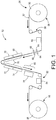
- Figure 1 depicts a schematic view of an embodiment of a present printing system, i.e., printing system 50.
- Thermoforming grade substrate 52 e.g., polyethylene terephthalate (PET) or polyvinyl chloride (PVC)
- PET polyethylene terephthalate
- PVC polyvinyl chloride
- Web 52 then passes through a conventional web drive and steering subsystem, i.e., subsystem 58.
- Web 52 is exposed to surface energy modification device 60, e.g., corona discharge, atmospheric plasma, or flame treatment.
- Surface energy modification device 60 enhances both the wetting and adhesion of ink 62 to web 52.
- printing system 50 may also include web cleaning stations 64 and static neutralization devices 66 to remove excess particles and static charge from the substrate.
- stations 64 and devices 66 are located on both sides of web 52 between surface energy modification device 60 and printhead array 68. Web 52 then passes by one or more printhead arrays, e.g., printhead arrays 68, 70, 72 and 74.
- each printhead array is composed of multiple piezo printheads arranged so that the full width of web 52, other than inboard and outboard margins, can be addressed by at least one printhead without the need to move or scan the printhead.
- the foregoing arrangement of printheads allows for a 'single pass' print mode in which web 52 moves continuously through print zone 76, i.e., the area where web 52 passes adjacent to printhead arrays 68, 70, 72 and 74. It has been found that the foregoing embodiments can print over a speed range of 30-120 feet per minute.
- the full width printhead arrays of system 50 are stationary, i.e., not scanning transversely across web 52, which enables much higher printing throughput than conventional printers.
- Figure 1 shows one printhead array for each of the four conventional colors, i.e ., cyan, magenta, yellow and black, also commonly referred to as CMYK.
- the four printhead arrays are represented by arrays 68, 70, 72 and 74 for the CMYK colors, respectively.
- An additional array or a plurality of additional arrays can be included for a fifth color, e.g., white, or for a plurality of additional colors.
- the printhead arrays are responsible for adding digitally defined image content to substrate 52, such as package graphics, instructions, and the like.
- the printhead arrays may also print non-image marks such as registration marks for subsequent thermoform processing, cutting operations, or other post printing processes that require alignment to the printed image.
- each printhead array supplies its corresponding printhead array with a radiation-curable thermoforming ink. It has been found that suitable inks should be formulated to allow for stretching of at least 400% elongation without cracking or losing adhesion to the substrate. However, the extent of necessary stretching is dependent on the thermoforming process and inks providing less than 400% elongation without cracking or loss of adhesion to the substrate may also be suitable for some applications.
- radiation curing device 78 may be selected from the group consisting of: an ultraviolet radiation source; an infrared radiation source; a visible light radiation source; and, combinations thereof, depending on the requirements of the stretchable ink.
- sensing subsystem 82 can be used to detect color-to-color registration, missing jets, and other print quality metrics.
- sensing subsystem 82 comprises full width array sensor 84.
- Web 52 then passes into rewinder 86 where printed web 52 is returned to a roll form, e.g., roll 88.
- Printed roll 88 can be used in a thermoforming press and thereby converted into thermoformed objects, e.g., food packaging containers.
- web substrate 52 is 0.36mm (0.014 inch) thick thermoforming grade PET, although other thermoformable plastics may also be used.
- print resolution of 600 dots per inch (dpi) x 600 dpi is acceptable, although other print modes may be used, e.g., 300 dpi x 300 dpi.
- system 50 is capable of printing at least one stretchable ink on a thermoformable substrate, e.g., substrate 52.
- system 50 comprises unwinder 56, surface energy modification device 60, at least one full width printhead array, e.g., printhead arrays 68, 70, 72 and 74, at least one radiation curing device, e.g., curing device 78, full width array sensor 84 and rewinder 86.
- Unwinder 56 is arranged to feed thermoformable substrate 52 from first roll 90 into web drive subsystem 58.
- Surface energy modification device 60 is arranged to alter a substrate surface energy to enhance wetting and adhesion of the at least one stretchable ink to thermoformable substrate 52.
- the full width printhead arrays are arranged to deposit the at least one stretchable ink on thermoformable substrate 52.
- Radiation curing device 78 is arranged to cure the at least one stretchable ink on thermoformable substrate 52.
- Full width array sensor 84 is arranged to monitor the at least one stretchable ink on thermoformable substrate 52, and rewinder 86 is arranged to receive thermoformable substrate 52 and to form thermoformable substrate 52 into second roll 88.
- each of the at least one stretchable ink is an ultraviolet radiation curable ink; however, other types of inks may also be used.
- thermoformable substrate 52 is selected from the group consisting of: polyethylene terephthalate; polyethylene terephthalate glycol-modified; polycarbonate; acrylic; polyvinyl chloride; acrylonitrile butadiene styrene; polypropylene; and, combinations thereof.
- thermoformable substrate 52 comprises a first width and surface energy modification device 60 comprises a second width/length greater than the first width.
- thermoformable substrate 52 comprises a first width and surface energy modification device 60 comprises a second width/length greater than the first width.
- each full width printhead array dispenses a unique stretchable ink.
- each full width printhead array dispenses a particular color unique to that printhead array.
- a first full width printhead array 68 may dispense cyan ink
- a second printhead array 70 dispenses magenta ink
- a third printhead array 72 dispenses yellow ink
- a fourth printhead array 74 dispenses black ink.
- thermoformable substrate 52 comprises a first width and the at least one full width printhead array, e.g., arrays 68, 70, 72 and/or 74, comprises a second width/length less than the first width.
- thermoformable or printable substrate it is also within the scope of the claims to have printhead arrays that are equal to or greater than the width of the thermoformable or printable substrate.
- some piezo printheads must be turned off, i.e ., the printheads falling outside of the substrate, to avoid waste of ink or damage to the overall system.
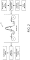
- Figure 2 depicts a schematic view of an embodiment of printer 50 within an example of a full thermoforming manufacturing process.
- the benefits of printing in a roll-to-roll mode are evident versus a fully integrated in-line system.
- throughput rates of extruders, printers, and thermoform presses it is possible for a highly flexible and reconfigurable manufacturing process with high uptime if any one component is down for servicing or otherwise unavailable for its contribution to the overall process.
- Figure 3 depicts a cross sectional view showing the interaction of stretchable ink 62 with thermoformable substrate 52 having a low surface energy
- Figure 4 depicts a cross sectional view showing the interaction of stretchable ink 62 with thermoformable substrate 52 having a surface energy higher than the surface energy depicted in Figure 3
- Surface energy modification e.g., corona treatment
- Some printable substrates e.g., polymer films, have chemically inert and non-porous surfaces with low surface tensions that cause poor reception of printing inks and coatings. Surface tensions are indicative of surface energy which is also commonly referred to as dyne level.
- Surface treatment such as corona treatment, increases the surface energy of the printable substrate, thereby improving print quality through improved wettability and adhesion of inks.
- a substrate will be wetted if its surface energy is higher than the surface energy of the ink.
- the level of surface energy modification depends on a variety of factors, including but not limited to the type of treatment used, the substrate and the ink characteristics.
- the required intensity of treatment i.e ., the number of watts per minute per substrate surface area W ⁇ min m 2 , is best determined for each combination of substrate and ink. The same determination should be made when using different production runs of the same substrate and/or ink to achieve optimal printing results.
- Figure 5 depicts a sample printed thermoform, i.e., thermoform article 92, as would be produced using the above described process.
- the roll was used in a thermoforming process at a different location.
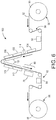
- Figure 6 depicts a schematic view of an embodiment of a present printing system for use in producing rolled printed thermoforming substrates, i.e., printing system 100.
- System 100 is similar to system 50 described above, with several additional elements.
- Thermoforming grade substrate 52 such as PET or PVC, is unwound in unwinder portion 56.
- Web 52 then passes through conventional web drive and steering components, i.e., subsystem 58. As the web drive and steering components are known in the art, they are not discussed in further detail herein.
- Web 52 is then exposed to surface energy modification device 60. Suitable surface energy modification devices include but are not limited to a corona treatment station, an atmospheric plasma treatment station, and a flame treatment station.
- the purpose of device 60 is to enhance both the wetting and adhesion of ink 62 to substrate 52. Both web cleaning stations and static neutralization devices to remove excess particles and static charge from the substrate may be included in system 100 but are not shown in this figure.
- Web 52 then passes into printing zone 102 which is composed of multiple printhead arrays, i.e ., printhead arrays 104, 106, 108, 110 and 112.
- printhead array is composed of multiple piezo printheads arranged so that the full width of web 52, other than inboard and outboard margins, can be addressed by at least one printhead. This arrangement allows for a 'single pass' print mode in which web 52 moves continuously through print zone 102.
- printhead array 104 which in this embodiment is associated with the color white, a common printed base layer.
- Array 104 prints a white background image.
- UV pinning device 114 is positioned after array 104 but before array 106 so that the ink deposited from array 104 is partially cured or 'pinned' to prevent subsequent mixing of inks with the background layer/image, e.g., the white background layer.
- the curing device or devices, as well as the pinning device may emit radiation other than ultraviolet radiation, and such radiation is dependent upon the requirements of the ink.
- the pinned white background is overprinted by the CMYK printhead arrays, i.e ., printhead arrays 106, 108, 110 and 112.
- web 52 After all ink has been deposited onto the background layer/image and/or substrate 52, web 52 then passes through curing zone 116.
- multiple wide spectrum UV lamps are used to cure the inks, although other devices such as UV spectrum LED arrays, or non-UV radiation sources are also suitable, depending on the requirements of the inks.
- sensing subsystem 82 which comprises full width array sensor 84 to detect color-to-color register, missing jets, and other print quality metrics.
- Web 52 then passes into rewinder 86 where printed web 52 is returned to a roll form, e.g., roll 88.
- Sensing subsystem 82 may be used to quantify the overall quality of printed web 52, thereby facilitating tuning or optimization of systems 50 and 100. Such optimization may include but is not limited to adjusting the web speed, tuning the surface energy modification, e.g., increasing or decreasing its input power, increasing or decreasing the quantity of printed ink, tuning one or more of the curing devices, etc.
- FIG. 6 shows a schematic view of printing system 100, which example embodiment improves the overall printed results.
- system 50 does not include pinning device 114, i.e., the pinning/curing device positioned immediately after the background layer/image printhead array.
- System 100 functions similarly to other embodiments described above.
- Web 52 is unwound by unwinder 56 and subsequently treated by exposure to surface energy modification device 60.
- Web 52 then passes printhead array 104 where a background layer/image is deposited on web 52.
- the background layer/image is fully cured in curing zone 80 by curing device 82, the background image is inspected by sensing subsystem 82 and subsequently rewound into roll 88 by rewinder 86.
- Roll 88 becomes the new roll 90 and is then refed though system 100 a second time.
- Web 52 having the background layer printed thereon is unwound by unwinder 56 and subsequently treated by exposure to surface energy modification device 60. In this instance, surface energy modification device 60 alters the surface energy of both web 52 and the background layer/image cured thereon.
- Web 52 with the background layer/image cured thereon then passes printhead arrays 106, 108, 110 and 112, i.e., printing zone 102, where a CMYK image is deposited on web 52 and/or the background layer.
- the CMYK image is fully cured in curing zone 80 by curing device 78, the completed image is inspected by sensing subsystem 82 and subsequently web 52 is rewound into roll 88 by rewinder 86.
- the foregoing embodiments deposit or print CMYKW images via two independent passes of substrate 52 through printer system 100, without the use of pinning device 114.
- a roll of material i.e., a roll of thermoformable substrate
- printer 100 twice.
- the first pass only the background layer/image is printed and then fully cured.
- print limited amounts of CMYK directly onto the substrate in order, for example, to create any registration marks or background layer other than white, and such printing can occur during the first pass through the printing system.
- the printed substrate resulting from the first pass is rewound into a roll and then reintroduced to the printing system for a second pass.
- the cured background layer/image is corona treated to enhance wetting of ink on its surface, i.e., the background layer/image is exposed to the surface energy modification device.
- the CMYK image content is aligned to any previously printed registration marks and is overprinted on the background layer/image and then fully cured.
- the substrate is rolled up a second time and is then in condition for installation onto a thermoforming press.
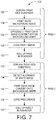
- printing process 120 The foregoing printing process is depicted in Figure 7 as printing process 120.
- Web 52 is fed into printing system 100 at unwinder 56 from roll 90.
- Web 52 is treated with surface energy modification device 60 at Step 122.
- a background layer/image e.g., a white background, is printed on web 52 by printhead array 104 at Step 124.
- CMYK image content may be printed on web 52 by printhead arrays 106, 108, 110 and 112 at Step 126.
- Such content may include but is not limited to fiducials, alignment marks, image content falling outside the background layer/image, etc.
- the collective printed image on web 52 from the first pass through printing system 100 is cured by curing device 78 at Step 128.
- Web 52 is then rewound by rewinder 86 into roll 88 at Step 130. Roll 88 then becomes the new roll 90 which is again fed into unwinder 56 of system 100.
- Web 52 now including the background layer/image and any CMYK first pass image(s), is treated with surface energy modification device 60 at Step 132. The position of the background layer/image is directly detected or detected via the position of alignment marks with position detection or sensing system 82 at Step 134.
- a CMYK image is printed on web 52 in whole or in part on the background layer/image by printhead arrays 106, 108, 110 and 112 at Step 136.
- the CMYK image on web 52 from the second pass through printing system 100 is cured by curing device 78 at Step 138.
- Web 52 is then rewound by rewinder 86 into roll 88 at Step 140.
- the present method for applying an image on a thermoformable substrate comprises the following. First, the surface energy of thermoformable substrate 52 is modified with surface energy modification device 60. Then, a background layer is deposited on at least a portion of substrate 52 with at least one full width printhead array 104. The background layer comprises at least one stretchable ink, e.g., a white ink. Next, the background layer is cured with at least one radiation curing device 78 to form a first printed substrate. The foregoing steps, i.e ., the first pass through system 100, are now largely repeated, i.e., the second pass through system 100. The surface energy of the first printed substrate is modified with surface energy modification device 60.
- a foreground layer is deposited on the background layer and/or substrate with at least one full width printhead array 106, 108, 110 and/or 112.
- the foreground layer comprises at least one stretchable ink, e.g., cyan, magenta, yellow and/or black ink.
- the foreground layer is cured with at least one radiation curing device 78 to form a second printed substrate.
- the foregoing method further comprises forming roll 88 of the first printed substrate using rewinder 86 after the first pass through system 100. Similarly, in some embodiments, the foregoing method further comprises forming roll 88 of the second printed substrate using rewinder 86 after the second pass through system 100.
- the printing system disclosed above provides a high throughput digital thermoform printer.
- Various embodiments and combinations of embodiments of the printing system include: a web unwinder; a treatment station to modify the substrate surface energy; a conventional web drive and tracking subsystem; one or more full-width arrays of printheads; an ink delivery subsystem; a radiation-curable ink set capable of stretching, e.g., by at least 400%, during thermoforming; one or more radiation curing devices; an in-line sensor to monitor print quality on the web; and, a rewinder.
- Benefits of the present printing system include but are not limited to: high throughput digital manufacturing capability for thermoformable materials; a digital (variable) printed labels which eliminate the need for adhesive backed paper or resin based labels; ease of recycling; and, the surface energy modifier also removes contamination.
- the present printing system reduces the costs associated with the production of labeled thermoformable containers by eliminating the steps of producing and applying a label.
- the present disclosure also includes a two-step process for printing on a web or substrate to be thermoformed.
- a background layer/image such as a white layer is printed and cured.
- the background layer/image is treated to alter its surface energy and the CMYK inks are then printed and cured.
- Benefits of these embodiments include that the method produces clearly improved results from alternative methods.
Landscapes
- Health & Medical Sciences (AREA)
- General Health & Medical Sciences (AREA)
- Toxicology (AREA)
- Physics & Mathematics (AREA)
- Electromagnetism (AREA)
- Ink Jet (AREA)
- Particle Formation And Scattering Control In Inkjet Printers (AREA)
Claims (6)
- Procédé pour appliquer une image sur un substrat thermoformable, comprenant :a) la modification (122) d'une première énergie de surface du substrat thermoformable avec un dispositif de modification d'énergie de surface ;b) la déposition (124) d'une couche de fond sur une partie du substrat avec au moins un réseau de têtes d'impression de pleine largeur, la couche de fond comprenant au moins une encre étirable, dans laquelle la première énergie de surface modifiée amplifie le mouillage et l'adhérence de l'au moins une encre étirable ;c) le durcissement (128) de la couche de fond pour former un premier substrat imprimé avec au moins un dispositif de durcissement par irradiation ;d) la modification (132) d'une deuxième énergie de surface avec au moins un dispositif de modification d'énergie de surface ;e) la déposition (136) d'une couche de premier plan sur la couche de fond avec au moins un réseau de têtes d'impression de pleine largeur, la couche de premier plan comprenant au moins une encre étirable, dans laquelle la deuxième énergie de surface modifiée amplifie le mouillage et l'adhérence de l'au moins une encre étirable ; etf) le durcissement (138) de la couche de premier plan pour former un deuxième substrat imprimé avec au moins un dispositif de durcissement par irradiation.
- Procédé pour appliquer une image sur un substrat thermoformable selon la revendication 1, comprenant en outre :
c1) la formation (130) d'un rouleau du premier substrat imprimé au moyen d'un enrouleur. - Procédé pour appliquer une image sur un substrat thermoformable selon la revendication 1, comprenant en outre :
f1) la formation (140) d'un rouleau du deuxième substrat imprimé au moyen d'un enrouleur. - Procédé pour appliquer une image sur un substrat thermoformable selon la revendication 1, dans lequel l'au moins une encre étirable est une encre durcissable par un rayonnement ultraviolet.
- Procédé pour appliquer une image sur un substrat thermoformable selon la revendication 1, dans lequel le substrat thermoformable est choisi dans le groupe constitué par : le poly(téréphtalate d'éthylène) modifié par un glycol ; le polycarbonate ; un acrylate ; le poly(chlorure de vinyle) ; l'acrylonitrile-butadiène-styrène ; et leurs combinaisons.
- Procédé selon l'une quelconque des revendications précédentes, dans lequel les étapes (a) et (d) comprennent l'exposition du substrat thermoformable à une décharge couronne, un plasma atmosphérique ou un traitement à la flamme.
Applications Claiming Priority (1)
| Application Number | Priority Date | Filing Date | Title |
|---|---|---|---|
| US15/166,874 US9827790B1 (en) | 2016-05-27 | 2016-05-27 | Printing device and method of using the same |
Publications (2)
| Publication Number | Publication Date |
|---|---|
| EP3248794A1 EP3248794A1 (fr) | 2017-11-29 |
| EP3248794B1 true EP3248794B1 (fr) | 2018-12-26 |
Family
ID=58772778
Family Applications (1)
| Application Number | Title | Priority Date | Filing Date |
|---|---|---|---|
| EP17172838.9A Active EP3248794B1 (fr) | 2016-05-27 | 2017-05-24 | Procédé d'utilisation d'une imprimante |
Country Status (4)
| Country | Link |
|---|---|
| US (2) | US9827790B1 (fr) |
| EP (1) | EP3248794B1 (fr) |
| JP (1) | JP6731378B2 (fr) |
| CN (1) | CN107433784B (fr) |
Families Citing this family (8)
| Publication number | Priority date | Publication date | Assignee | Title |
|---|---|---|---|---|
| US11225066B2 (en) | 2017-03-29 | 2022-01-18 | Xerox Corporation | In-line detection and correction of underperforming light emitting diodes in a curing station of a three dimensional object printer |
| US10807354B2 (en) * | 2017-03-29 | 2020-10-20 | Xerox Corporation | Active light emitting diode ultra violet curing system for a three dimensional object printer |
| US10688773B2 (en) | 2017-03-29 | 2020-06-23 | Xerox Corporation | Cure confirmation system and method for three dimensional object printer |
| US10406831B2 (en) | 2017-09-21 | 2019-09-10 | Xerox Corporation | Thermoformable overcoat in roll-to-roll format printers for thermoforming applications |
| US20190240897A1 (en) * | 2018-02-07 | 2019-08-08 | Xerox Corporation | Transfer of uv print onto curved surfaces with stretchable uv inks |
| US11766822B2 (en) | 2019-08-20 | 2023-09-26 | 3M Innovative Properties Company | Microstructured surface with increased microorganism removal when cleaned, articles and methods |
| NL2024561B1 (en) * | 2019-12-23 | 2021-09-02 | Xeikon Mfg Nv | Digital printing process and resulting packaging material |
| CN115384187B (zh) * | 2022-08-02 | 2023-08-22 | 广州精陶机电设备有限公司 | 一种具有外置烘干的喷墨印刷系统 |
Citations (1)
| Publication number | Priority date | Publication date | Assignee | Title |
|---|---|---|---|---|
| US20150251453A1 (en) * | 2014-03-07 | 2015-09-10 | Ricoh Company, Ltd. | Plasma processing device, printing apparatus, printing system, computer program product, and method for manufacturing printed material |
Family Cites Families (27)
| Publication number | Priority date | Publication date | Assignee | Title |
|---|---|---|---|---|
| FR2784619B1 (fr) * | 1998-10-14 | 2000-11-24 | Enduction Et De Flockage Soc D | Procede d'impression en continu d'un film plastique plan, destine a etre thermoforme en une surface non plane et film thermoforme obtenu par ce procede |
| US6942832B2 (en) * | 2002-07-29 | 2005-09-13 | Ivonis M. Mazzarolo | Method of manufacturing vacuum thermoformed thin plastic drink cup lids |
| US20040135828A1 (en) * | 2003-01-15 | 2004-07-15 | Schmitt Stephen E. | Printer and method for printing an item with a high durability and/or resolution image |
| JP4556444B2 (ja) * | 2003-03-27 | 2010-10-06 | コニカミノルタホールディングス株式会社 | 画像記録装置 |
| US6942308B2 (en) * | 2003-10-10 | 2005-09-13 | Hewlett-Packard Development Company, L.P. | Compensation of lateral position changes in printing |
| US7387352B2 (en) | 2004-10-19 | 2008-06-17 | Eastman Kodak Company | Print optimization system and method for drop on demand ink jet printers |
| JP5106199B2 (ja) | 2008-03-25 | 2012-12-26 | 富士フイルム株式会社 | 画像形成方法および画像形成装置 |
| JP2010076404A (ja) * | 2008-09-29 | 2010-04-08 | Fujifilm Corp | 液体硬化装置、画像形成装置、液体硬化方法および画像形成方法 |
| EP2424944B1 (fr) * | 2009-04-27 | 2016-03-16 | Sun Chemical B.V. | Encre pour jet d'encre de thermoformage à allongement élevé |
| US8322841B2 (en) * | 2010-03-16 | 2012-12-04 | Xerox Corporation | Inkjet printing apparatus |
| US8319202B2 (en) | 2010-04-06 | 2012-11-27 | Xerox Corporation | Color registration strategy for preprinted forms |
| WO2012033955A2 (fr) | 2010-09-08 | 2012-03-15 | Avery Dennison Corporation | Etiquetage thermoformé |
| JP6003132B2 (ja) * | 2012-03-21 | 2016-10-05 | セイコーエプソン株式会社 | 画像記録装置、画像記録方法 |
| US20130288018A1 (en) * | 2012-04-30 | 2013-10-31 | Patrick W. Moller | System and method for printing on plastic and forming the printed plastic |
| US8939536B2 (en) * | 2012-05-02 | 2015-01-27 | Xerox Corporation | Method and system for aligning printheads that eject clear ink in an inkjet printer |
| US8840241B2 (en) | 2012-08-20 | 2014-09-23 | Xerox Corporation | System and method for adjusting an electrostatic field in an inkjet printer |
| JP6487618B2 (ja) * | 2012-09-18 | 2019-03-20 | 株式会社リコー | 印刷装置、印刷システムおよび印刷物の製造方法 |
| US9259924B2 (en) * | 2012-09-18 | 2016-02-16 | Ricoh Company, Ltd. | Printing apparatus and printed material manufacturing method |
| JP6314417B2 (ja) | 2012-12-12 | 2018-04-25 | 株式会社リコー | 印刷装置、印刷物の製造方法および印刷システム |
| US8933148B2 (en) | 2013-02-06 | 2015-01-13 | Xerox Corporation | Solventless radiation curable stretchable ink composition |
| JP5788918B2 (ja) | 2013-02-19 | 2015-10-07 | 富士フイルム株式会社 | インクジェット記録方法及びインクジェット記録装置 |
| JP6503713B2 (ja) | 2014-03-11 | 2019-04-24 | 株式会社リコー | 印刷装置、印刷システムおよび印刷物の製造方法 |
| JP6435896B2 (ja) | 2014-03-14 | 2018-12-12 | 株式会社リコー | 被処理物改質装置、印刷装置、印刷システムおよび印刷物の製造方法 |
| JP6304489B2 (ja) | 2014-04-01 | 2018-04-04 | セイコーエプソン株式会社 | インクジェットプリンタ及びその制御方法 |
| US20150283803A1 (en) * | 2014-04-07 | 2015-10-08 | Christopher M. Muir | Method for preventing flutes on a non-print side |
| US9289969B2 (en) * | 2014-06-27 | 2016-03-22 | Disney Enterprises, Inc. | Rear projected screen materials and processes |
| JP6398521B2 (ja) * | 2014-09-22 | 2018-10-03 | カシオ計算機株式会社 | 印刷装置、印刷方法及びプログラム |
-
2016
- 2016-05-27 US US15/166,874 patent/US9827790B1/en active Active
-
2017
- 2017-05-04 CN CN201710307812.4A patent/CN107433784B/zh active Active
- 2017-05-10 JP JP2017093459A patent/JP6731378B2/ja active Active
- 2017-05-24 EP EP17172838.9A patent/EP3248794B1/fr active Active
- 2017-10-09 US US15/728,003 patent/US10875326B2/en active Active
Patent Citations (1)
| Publication number | Priority date | Publication date | Assignee | Title |
|---|---|---|---|---|
| US20150251453A1 (en) * | 2014-03-07 | 2015-09-10 | Ricoh Company, Ltd. | Plasma processing device, printing apparatus, printing system, computer program product, and method for manufacturing printed material |
Also Published As
| Publication number | Publication date |
|---|---|
| CN107433784B (zh) | 2020-02-21 |
| US10875326B2 (en) | 2020-12-29 |
| JP6731378B2 (ja) | 2020-07-29 |
| CN107433784A (zh) | 2017-12-05 |
| EP3248794A1 (fr) | 2017-11-29 |
| JP2017209989A (ja) | 2017-11-30 |
| US9827790B1 (en) | 2017-11-28 |
| US20170341415A1 (en) | 2017-11-30 |
| US20180029381A1 (en) | 2018-02-01 |
Similar Documents
| Publication | Publication Date | Title |
|---|---|---|
| EP3248794B1 (fr) | Procédé d'utilisation d'une imprimante | |
| US20180126753A1 (en) | Method of single pass printing of multiple colors | |
| US8851609B2 (en) | Inkjet recording apparatus | |
| CN102470668B (zh) | 喷墨打印机以及喷墨印刷方法 | |
| CN104039555A (zh) | 用于减少光泽带的样式化透明层应用的打印系统 | |
| EP1428669B1 (fr) | Imprimante à jet d'encre | |
| US11130353B2 (en) | Thermoformable overcoat in roll-to-roll format printers for thermoforming applications | |
| US20120293593A1 (en) | Printing apparatus and printing method | |
| US8960841B2 (en) | Printing apparatus and printing method | |
| CN115402017B (zh) | 在容器上制造浮雕状印刷图像的方法 | |
| JP2004237588A (ja) | インクジェット記録装置 | |
| EP3248805A1 (fr) | Système de prétraitement d'énergie de surface en temps réel | |
| US7338154B2 (en) | Image recording apparatus | |
| JP5299144B2 (ja) | 印刷装置、及び、印刷方法 | |
| CN115190843B (zh) | 用于套准和打印柔性幅材的系统和方法 | |
| US20230026904A1 (en) | System and method for printing on a clear polymeric film web | |
| JP2011031584A (ja) | 印刷装置及び印刷方法 | |
| CN111479695A (zh) | 解卷部以及相邻卷绕部偏置型喷墨打印机 | |
| US20170341417A1 (en) | Flexible, modular architecture for a digital printer |
Legal Events
| Date | Code | Title | Description |
|---|---|---|---|
| PUAI | Public reference made under article 153(3) epc to a published international application that has entered the european phase |
Free format text: ORIGINAL CODE: 0009012 |
|
| STAA | Information on the status of an ep patent application or granted ep patent |
Free format text: STATUS: THE APPLICATION HAS BEEN PUBLISHED |
|
| AK | Designated contracting states |
Kind code of ref document: A1 Designated state(s): AL AT BE BG CH CY CZ DE DK EE ES FI FR GB GR HR HU IE IS IT LI LT LU LV MC MK MT NL NO PL PT RO RS SE SI SK SM TR |
|
| AX | Request for extension of the european patent |
Extension state: BA ME |
|
| STAA | Information on the status of an ep patent application or granted ep patent |
Free format text: STATUS: REQUEST FOR EXAMINATION WAS MADE |
|
| 17P | Request for examination filed |
Effective date: 20180529 |
|
| RBV | Designated contracting states (corrected) |
Designated state(s): AL AT BE BG CH CY CZ DE DK EE ES FI FR GB GR HR HU IE IS IT LI LT LU LV MC MK MT NL NO PL PT RO RS SE SI SK SM TR |
|
| GRAP | Despatch of communication of intention to grant a patent |
Free format text: ORIGINAL CODE: EPIDOSNIGR1 |
|
| STAA | Information on the status of an ep patent application or granted ep patent |
Free format text: STATUS: GRANT OF PATENT IS INTENDED |
|
| INTG | Intention to grant announced |
Effective date: 20180717 |
|
| GRAS | Grant fee paid |
Free format text: ORIGINAL CODE: EPIDOSNIGR3 |
|
| GRAA | (expected) grant |
Free format text: ORIGINAL CODE: 0009210 |
|
| STAA | Information on the status of an ep patent application or granted ep patent |
Free format text: STATUS: THE PATENT HAS BEEN GRANTED |
|
| AK | Designated contracting states |
Kind code of ref document: B1 Designated state(s): AL AT BE BG CH CY CZ DE DK EE ES FI FR GB GR HR HU IE IS IT LI LT LU LV MC MK MT NL NO PL PT RO RS SE SI SK SM TR |
|
| REG | Reference to a national code |
Ref country code: GB Ref legal event code: FG4D |
|
| REG | Reference to a national code |
Ref country code: CH Ref legal event code: EP |
|
| REG | Reference to a national code |
Ref country code: AT Ref legal event code: REF Ref document number: 1080858 Country of ref document: AT Kind code of ref document: T Effective date: 20190115 |
|
| REG | Reference to a national code |
Ref country code: DE Ref legal event code: R096 Ref document number: 602017001555 Country of ref document: DE |
|
| REG | Reference to a national code |
Ref country code: IE Ref legal event code: FG4D |
|
| PG25 | Lapsed in a contracting state [announced via postgrant information from national office to epo] |
Ref country code: LV Free format text: LAPSE BECAUSE OF FAILURE TO SUBMIT A TRANSLATION OF THE DESCRIPTION OR TO PAY THE FEE WITHIN THE PRESCRIBED TIME-LIMIT Effective date: 20181226 Ref country code: FI Free format text: LAPSE BECAUSE OF FAILURE TO SUBMIT A TRANSLATION OF THE DESCRIPTION OR TO PAY THE FEE WITHIN THE PRESCRIBED TIME-LIMIT Effective date: 20181226 Ref country code: HR Free format text: LAPSE BECAUSE OF FAILURE TO SUBMIT A TRANSLATION OF THE DESCRIPTION OR TO PAY THE FEE WITHIN THE PRESCRIBED TIME-LIMIT Effective date: 20181226 Ref country code: NO Free format text: LAPSE BECAUSE OF FAILURE TO SUBMIT A TRANSLATION OF THE DESCRIPTION OR TO PAY THE FEE WITHIN THE PRESCRIBED TIME-LIMIT Effective date: 20190326 Ref country code: BG Free format text: LAPSE BECAUSE OF FAILURE TO SUBMIT A TRANSLATION OF THE DESCRIPTION OR TO PAY THE FEE WITHIN THE PRESCRIBED TIME-LIMIT Effective date: 20190326 Ref country code: LT Free format text: LAPSE BECAUSE OF FAILURE TO SUBMIT A TRANSLATION OF THE DESCRIPTION OR TO PAY THE FEE WITHIN THE PRESCRIBED TIME-LIMIT Effective date: 20181226 |
|
| REG | Reference to a national code |
Ref country code: NL Ref legal event code: MP Effective date: 20181226 |
|
| REG | Reference to a national code |
Ref country code: LT Ref legal event code: MG4D |
|
| PG25 | Lapsed in a contracting state [announced via postgrant information from national office to epo] |
Ref country code: SE Free format text: LAPSE BECAUSE OF FAILURE TO SUBMIT A TRANSLATION OF THE DESCRIPTION OR TO PAY THE FEE WITHIN THE PRESCRIBED TIME-LIMIT Effective date: 20181226 Ref country code: GR Free format text: LAPSE BECAUSE OF FAILURE TO SUBMIT A TRANSLATION OF THE DESCRIPTION OR TO PAY THE FEE WITHIN THE PRESCRIBED TIME-LIMIT Effective date: 20190327 Ref country code: RS Free format text: LAPSE BECAUSE OF FAILURE TO SUBMIT A TRANSLATION OF THE DESCRIPTION OR TO PAY THE FEE WITHIN THE PRESCRIBED TIME-LIMIT Effective date: 20181226 Ref country code: AL Free format text: LAPSE BECAUSE OF FAILURE TO SUBMIT A TRANSLATION OF THE DESCRIPTION OR TO PAY THE FEE WITHIN THE PRESCRIBED TIME-LIMIT Effective date: 20181226 |
|
| REG | Reference to a national code |
Ref country code: AT Ref legal event code: MK05 Ref document number: 1080858 Country of ref document: AT Kind code of ref document: T Effective date: 20181226 |
|
| PG25 | Lapsed in a contracting state [announced via postgrant information from national office to epo] |
Ref country code: NL Free format text: LAPSE BECAUSE OF FAILURE TO SUBMIT A TRANSLATION OF THE DESCRIPTION OR TO PAY THE FEE WITHIN THE PRESCRIBED TIME-LIMIT Effective date: 20181226 |
|
| PG25 | Lapsed in a contracting state [announced via postgrant information from national office to epo] |
Ref country code: PT Free format text: LAPSE BECAUSE OF FAILURE TO SUBMIT A TRANSLATION OF THE DESCRIPTION OR TO PAY THE FEE WITHIN THE PRESCRIBED TIME-LIMIT Effective date: 20190426 Ref country code: CZ Free format text: LAPSE BECAUSE OF FAILURE TO SUBMIT A TRANSLATION OF THE DESCRIPTION OR TO PAY THE FEE WITHIN THE PRESCRIBED TIME-LIMIT Effective date: 20181226 Ref country code: ES Free format text: LAPSE BECAUSE OF FAILURE TO SUBMIT A TRANSLATION OF THE DESCRIPTION OR TO PAY THE FEE WITHIN THE PRESCRIBED TIME-LIMIT Effective date: 20181226 Ref country code: PL Free format text: LAPSE BECAUSE OF FAILURE TO SUBMIT A TRANSLATION OF THE DESCRIPTION OR TO PAY THE FEE WITHIN THE PRESCRIBED TIME-LIMIT Effective date: 20181226 Ref country code: IT Free format text: LAPSE BECAUSE OF FAILURE TO SUBMIT A TRANSLATION OF THE DESCRIPTION OR TO PAY THE FEE WITHIN THE PRESCRIBED TIME-LIMIT Effective date: 20181226 |
|
| PG25 | Lapsed in a contracting state [announced via postgrant information from national office to epo] |
Ref country code: EE Free format text: LAPSE BECAUSE OF FAILURE TO SUBMIT A TRANSLATION OF THE DESCRIPTION OR TO PAY THE FEE WITHIN THE PRESCRIBED TIME-LIMIT Effective date: 20181226 Ref country code: SM Free format text: LAPSE BECAUSE OF FAILURE TO SUBMIT A TRANSLATION OF THE DESCRIPTION OR TO PAY THE FEE WITHIN THE PRESCRIBED TIME-LIMIT Effective date: 20181226 Ref country code: IS Free format text: LAPSE BECAUSE OF FAILURE TO SUBMIT A TRANSLATION OF THE DESCRIPTION OR TO PAY THE FEE WITHIN THE PRESCRIBED TIME-LIMIT Effective date: 20190426 Ref country code: SK Free format text: LAPSE BECAUSE OF FAILURE TO SUBMIT A TRANSLATION OF THE DESCRIPTION OR TO PAY THE FEE WITHIN THE PRESCRIBED TIME-LIMIT Effective date: 20181226 Ref country code: RO Free format text: LAPSE BECAUSE OF FAILURE TO SUBMIT A TRANSLATION OF THE DESCRIPTION OR TO PAY THE FEE WITHIN THE PRESCRIBED TIME-LIMIT Effective date: 20181226 |
|
| REG | Reference to a national code |
Ref country code: DE Ref legal event code: R097 Ref document number: 602017001555 Country of ref document: DE |
|
| PG25 | Lapsed in a contracting state [announced via postgrant information from national office to epo] |
Ref country code: DK Free format text: LAPSE BECAUSE OF FAILURE TO SUBMIT A TRANSLATION OF THE DESCRIPTION OR TO PAY THE FEE WITHIN THE PRESCRIBED TIME-LIMIT Effective date: 20181226 Ref country code: AT Free format text: LAPSE BECAUSE OF FAILURE TO SUBMIT A TRANSLATION OF THE DESCRIPTION OR TO PAY THE FEE WITHIN THE PRESCRIBED TIME-LIMIT Effective date: 20181226 |
|
| PLBE | No opposition filed within time limit |
Free format text: ORIGINAL CODE: 0009261 |
|
| STAA | Information on the status of an ep patent application or granted ep patent |
Free format text: STATUS: NO OPPOSITION FILED WITHIN TIME LIMIT |
|
| 26N | No opposition filed |
Effective date: 20190927 |
|
| PG25 | Lapsed in a contracting state [announced via postgrant information from national office to epo] |
Ref country code: MC Free format text: LAPSE BECAUSE OF FAILURE TO SUBMIT A TRANSLATION OF THE DESCRIPTION OR TO PAY THE FEE WITHIN THE PRESCRIBED TIME-LIMIT Effective date: 20181226 |
|
| REG | Reference to a national code |
Ref country code: BE Ref legal event code: MM Effective date: 20190531 |
|
| PG25 | Lapsed in a contracting state [announced via postgrant information from national office to epo] |
Ref country code: SI Free format text: LAPSE BECAUSE OF FAILURE TO SUBMIT A TRANSLATION OF THE DESCRIPTION OR TO PAY THE FEE WITHIN THE PRESCRIBED TIME-LIMIT Effective date: 20181226 Ref country code: LU Free format text: LAPSE BECAUSE OF NON-PAYMENT OF DUE FEES Effective date: 20190524 |
|
| PG25 | Lapsed in a contracting state [announced via postgrant information from national office to epo] |
Ref country code: TR Free format text: LAPSE BECAUSE OF FAILURE TO SUBMIT A TRANSLATION OF THE DESCRIPTION OR TO PAY THE FEE WITHIN THE PRESCRIBED TIME-LIMIT Effective date: 20181226 |
|
| PG25 | Lapsed in a contracting state [announced via postgrant information from national office to epo] |
Ref country code: IE Free format text: LAPSE BECAUSE OF NON-PAYMENT OF DUE FEES Effective date: 20190524 |
|
| PG25 | Lapsed in a contracting state [announced via postgrant information from national office to epo] |
Ref country code: BE Free format text: LAPSE BECAUSE OF NON-PAYMENT OF DUE FEES Effective date: 20190531 |
|
| PG25 | Lapsed in a contracting state [announced via postgrant information from national office to epo] |
Ref country code: LI Free format text: LAPSE BECAUSE OF NON-PAYMENT OF DUE FEES Effective date: 20200531 Ref country code: CH Free format text: LAPSE BECAUSE OF NON-PAYMENT OF DUE FEES Effective date: 20200531 |
|
| PG25 | Lapsed in a contracting state [announced via postgrant information from national office to epo] |
Ref country code: CY Free format text: LAPSE BECAUSE OF FAILURE TO SUBMIT A TRANSLATION OF THE DESCRIPTION OR TO PAY THE FEE WITHIN THE PRESCRIBED TIME-LIMIT Effective date: 20181226 |
|
| PG25 | Lapsed in a contracting state [announced via postgrant information from national office to epo] |
Ref country code: MT Free format text: LAPSE BECAUSE OF FAILURE TO SUBMIT A TRANSLATION OF THE DESCRIPTION OR TO PAY THE FEE WITHIN THE PRESCRIBED TIME-LIMIT Effective date: 20181226 Ref country code: HU Free format text: LAPSE BECAUSE OF FAILURE TO SUBMIT A TRANSLATION OF THE DESCRIPTION OR TO PAY THE FEE WITHIN THE PRESCRIBED TIME-LIMIT; INVALID AB INITIO Effective date: 20170524 |
|
| PG25 | Lapsed in a contracting state [announced via postgrant information from national office to epo] |
Ref country code: MK Free format text: LAPSE BECAUSE OF FAILURE TO SUBMIT A TRANSLATION OF THE DESCRIPTION OR TO PAY THE FEE WITHIN THE PRESCRIBED TIME-LIMIT Effective date: 20181226 |
|
| PGFP | Annual fee paid to national office [announced via postgrant information from national office to epo] |
Ref country code: GB Payment date: 20220425 Year of fee payment: 6 |
|
| GBPC | Gb: european patent ceased through non-payment of renewal fee |
Effective date: 20230524 |
|
| PG25 | Lapsed in a contracting state [announced via postgrant information from national office to epo] |
Ref country code: GB Free format text: LAPSE BECAUSE OF NON-PAYMENT OF DUE FEES Effective date: 20230524 |
|
| PGFP | Annual fee paid to national office [announced via postgrant information from national office to epo] |
Ref country code: DE Payment date: 20240418 Year of fee payment: 8 |
|
| PGFP | Annual fee paid to national office [announced via postgrant information from national office to epo] |
Ref country code: FR Payment date: 20240418 Year of fee payment: 8 |