EP3248488B1 - Dispositif à fumer électronique et atomiseur - Google Patents
Dispositif à fumer électronique et atomiseur Download PDFInfo
- Publication number
- EP3248488B1 EP3248488B1 EP17176368.3A EP17176368A EP3248488B1 EP 3248488 B1 EP3248488 B1 EP 3248488B1 EP 17176368 A EP17176368 A EP 17176368A EP 3248488 B1 EP3248488 B1 EP 3248488B1
- Authority
- EP
- European Patent Office
- Prior art keywords
- section
- atomizer
- wick
- electronic smoking
- winding
- Prior art date
- Legal status (The legal status is an assumption and is not a legal conclusion. Google has not performed a legal analysis and makes no representation as to the accuracy of the status listed.)
- Active
Links
- 230000000391 smoking effect Effects 0.000 title claims description 63
- 238000010438 heat treatment Methods 0.000 claims description 94
- 238000004804 winding Methods 0.000 claims description 75
- 239000000463 material Substances 0.000 claims description 39
- 239000007788 liquid Substances 0.000 description 92
- 230000008901 benefit Effects 0.000 description 10
- 239000000443 aerosol Substances 0.000 description 8
- 230000008016 vaporization Effects 0.000 description 5
- 230000004913 activation Effects 0.000 description 4
- 239000003814 drug Substances 0.000 description 3
- 239000003571 electronic cigarette Substances 0.000 description 3
- 230000001007 puffing effect Effects 0.000 description 3
- 238000005476 soldering Methods 0.000 description 3
- 238000003466 welding Methods 0.000 description 3
- RYGMFSIKBFXOCR-UHFFFAOYSA-N Copper Chemical compound [Cu] RYGMFSIKBFXOCR-UHFFFAOYSA-N 0.000 description 2
- 230000009471 action Effects 0.000 description 2
- 229910045601 alloy Inorganic materials 0.000 description 2
- 239000000956 alloy Substances 0.000 description 2
- 229910052782 aluminium Inorganic materials 0.000 description 2
- XAGFODPZIPBFFR-UHFFFAOYSA-N aluminium Chemical compound [Al] XAGFODPZIPBFFR-UHFFFAOYSA-N 0.000 description 2
- 230000008859 change Effects 0.000 description 2
- 235000019504 cigarettes Nutrition 0.000 description 2
- 229910052802 copper Inorganic materials 0.000 description 2
- 239000010949 copper Substances 0.000 description 2
- 239000000835 fiber Substances 0.000 description 2
- 239000012567 medical material Substances 0.000 description 2
- 229910001120 nichrome Inorganic materials 0.000 description 2
- 239000004033 plastic Substances 0.000 description 2
- 230000004044 response Effects 0.000 description 2
- SNICXCGAKADSCV-JTQLQIEISA-N (-)-Nicotine Chemical compound CN1CCC[C@H]1C1=CC=CN=C1 SNICXCGAKADSCV-JTQLQIEISA-N 0.000 description 1
- 229910000831 Steel Inorganic materials 0.000 description 1
- 230000003213 activating effect Effects 0.000 description 1
- POIUWJQBRNEFGX-XAMSXPGMSA-N cathelicidin Chemical compound C([C@@H](C(=O)N[C@@H](CCCNC(N)=N)C(=O)N[C@@H](CCCCN)C(=O)N[C@@H](CO)C(=O)N[C@@H](CCCCN)C(=O)N[C@@H](CCC(O)=O)C(=O)N[C@@H](CCCCN)C(=O)N[C@@H]([C@@H](C)CC)C(=O)NCC(=O)N[C@@H](CCCCN)C(=O)N[C@@H](CCC(O)=O)C(=O)N[C@@H](CC=1C=CC=CC=1)C(=O)N[C@@H](CCCCN)C(=O)N[C@@H](CCCNC(N)=N)C(=O)N[C@@H]([C@@H](C)CC)C(=O)N[C@@H](C(C)C)C(=O)N[C@@H](CCC(N)=O)C(=O)N[C@@H](CCCNC(N)=N)C(=O)N[C@@H]([C@@H](C)CC)C(=O)N[C@@H](CCCCN)C(=O)N[C@@H](CC(O)=O)C(=O)N[C@@H](CC=1C=CC=CC=1)C(=O)N[C@@H](CC(C)C)C(=O)N[C@@H](CCCNC(N)=N)C(=O)N[C@@H](CC(N)=O)C(=O)N[C@@H](CC(C)C)C(=O)N[C@@H](C(C)C)C(=O)N1[C@@H](CCC1)C(=O)N[C@@H](CCCNC(N)=N)C(=O)N[C@@H]([C@@H](C)O)C(=O)N[C@@H](CCC(O)=O)C(=O)N[C@@H](CO)C(O)=O)NC(=O)[C@H](CC=1C=CC=CC=1)NC(=O)[C@H](CC(O)=O)NC(=O)CNC(=O)[C@H](CC(C)C)NC(=O)[C@@H](N)CC(C)C)C1=CC=CC=C1 POIUWJQBRNEFGX-XAMSXPGMSA-N 0.000 description 1
- 238000001514 detection method Methods 0.000 description 1
- 238000001704 evaporation Methods 0.000 description 1
- 239000011152 fibreglass Substances 0.000 description 1
- 239000002657 fibrous material Substances 0.000 description 1
- 238000004519 manufacturing process Methods 0.000 description 1
- 239000012528 membrane Substances 0.000 description 1
- 229910052751 metal Inorganic materials 0.000 description 1
- 239000002184 metal Substances 0.000 description 1
- 230000004048 modification Effects 0.000 description 1
- 238000012986 modification Methods 0.000 description 1
- 229960002715 nicotine Drugs 0.000 description 1
- SNICXCGAKADSCV-UHFFFAOYSA-N nicotine Natural products CN1CCCC1C1=CC=CN=C1 SNICXCGAKADSCV-UHFFFAOYSA-N 0.000 description 1
- 239000011148 porous material Substances 0.000 description 1
- 239000010959 steel Substances 0.000 description 1
- 230000001131 transforming effect Effects 0.000 description 1
Images


Classifications
-
- H—ELECTRICITY
- H05—ELECTRIC TECHNIQUES NOT OTHERWISE PROVIDED FOR
- H05B—ELECTRIC HEATING; ELECTRIC LIGHT SOURCES NOT OTHERWISE PROVIDED FOR; CIRCUIT ARRANGEMENTS FOR ELECTRIC LIGHT SOURCES, IN GENERAL
- H05B3/00—Ohmic-resistance heating
- H05B3/40—Heating elements having the shape of rods or tubes
- H05B3/42—Heating elements having the shape of rods or tubes non-flexible
- H05B3/44—Heating elements having the shape of rods or tubes non-flexible heating conductor arranged within rods or tubes of insulating material
-
- A—HUMAN NECESSITIES
- A61—MEDICAL OR VETERINARY SCIENCE; HYGIENE
- A61M—DEVICES FOR INTRODUCING MEDIA INTO, OR ONTO, THE BODY; DEVICES FOR TRANSDUCING BODY MEDIA OR FOR TAKING MEDIA FROM THE BODY; DEVICES FOR PRODUCING OR ENDING SLEEP OR STUPOR
- A61M15/00—Inhalators
- A61M15/06—Inhaling appliances shaped like cigars, cigarettes or pipes
-
- A—HUMAN NECESSITIES
- A24—TOBACCO; CIGARS; CIGARETTES; SIMULATED SMOKING DEVICES; SMOKERS' REQUISITES
- A24F—SMOKERS' REQUISITES; MATCH BOXES; SIMULATED SMOKING DEVICES
- A24F40/00—Electrically operated smoking devices; Component parts thereof; Manufacture thereof; Maintenance or testing thereof; Charging means specially adapted therefor
- A24F40/40—Constructional details, e.g. connection of cartridges and battery parts
- A24F40/44—Wicks
-
- A—HUMAN NECESSITIES
- A24—TOBACCO; CIGARS; CIGARETTES; SIMULATED SMOKING DEVICES; SMOKERS' REQUISITES
- A24F—SMOKERS' REQUISITES; MATCH BOXES; SIMULATED SMOKING DEVICES
- A24F40/00—Electrically operated smoking devices; Component parts thereof; Manufacture thereof; Maintenance or testing thereof; Charging means specially adapted therefor
- A24F40/40—Constructional details, e.g. connection of cartridges and battery parts
- A24F40/46—Shape or structure of electric heating means
-
- A—HUMAN NECESSITIES
- A61—MEDICAL OR VETERINARY SCIENCE; HYGIENE
- A61M—DEVICES FOR INTRODUCING MEDIA INTO, OR ONTO, THE BODY; DEVICES FOR TRANSDUCING BODY MEDIA OR FOR TAKING MEDIA FROM THE BODY; DEVICES FOR PRODUCING OR ENDING SLEEP OR STUPOR
- A61M11/00—Sprayers or atomisers specially adapted for therapeutic purposes
- A61M11/04—Sprayers or atomisers specially adapted for therapeutic purposes operated by the vapour pressure of the liquid to be sprayed or atomised
- A61M11/041—Sprayers or atomisers specially adapted for therapeutic purposes operated by the vapour pressure of the liquid to be sprayed or atomised using heaters
- A61M11/042—Sprayers or atomisers specially adapted for therapeutic purposes operated by the vapour pressure of the liquid to be sprayed or atomised using heaters electrical
-
- A—HUMAN NECESSITIES
- A24—TOBACCO; CIGARS; CIGARETTES; SIMULATED SMOKING DEVICES; SMOKERS' REQUISITES
- A24F—SMOKERS' REQUISITES; MATCH BOXES; SIMULATED SMOKING DEVICES
- A24F40/00—Electrically operated smoking devices; Component parts thereof; Manufacture thereof; Maintenance or testing thereof; Charging means specially adapted therefor
- A24F40/10—Devices using liquid inhalable precursors
-
- A—HUMAN NECESSITIES
- A61—MEDICAL OR VETERINARY SCIENCE; HYGIENE
- A61M—DEVICES FOR INTRODUCING MEDIA INTO, OR ONTO, THE BODY; DEVICES FOR TRANSDUCING BODY MEDIA OR FOR TAKING MEDIA FROM THE BODY; DEVICES FOR PRODUCING OR ENDING SLEEP OR STUPOR
- A61M15/00—Inhalators
- A61M15/0001—Details of inhalators; Constructional features thereof
- A61M15/0021—Mouthpieces therefor
- A61M15/0025—Mouthpieces therefor with caps
-
- A—HUMAN NECESSITIES
- A61—MEDICAL OR VETERINARY SCIENCE; HYGIENE
- A61M—DEVICES FOR INTRODUCING MEDIA INTO, OR ONTO, THE BODY; DEVICES FOR TRANSDUCING BODY MEDIA OR FOR TAKING MEDIA FROM THE BODY; DEVICES FOR PRODUCING OR ENDING SLEEP OR STUPOR
- A61M16/00—Devices for influencing the respiratory system of patients by gas treatment, e.g. mouth-to-mouth respiration; Tracheal tubes
- A61M16/0003—Accessories therefor, e.g. sensors, vibrators, negative pressure
- A61M2016/0015—Accessories therefor, e.g. sensors, vibrators, negative pressure inhalation detectors
- A61M2016/0018—Accessories therefor, e.g. sensors, vibrators, negative pressure inhalation detectors electrical
- A61M2016/0024—Accessories therefor, e.g. sensors, vibrators, negative pressure inhalation detectors electrical with an on-off output signal, e.g. from a switch
-
- A—HUMAN NECESSITIES
- A61—MEDICAL OR VETERINARY SCIENCE; HYGIENE
- A61M—DEVICES FOR INTRODUCING MEDIA INTO, OR ONTO, THE BODY; DEVICES FOR TRANSDUCING BODY MEDIA OR FOR TAKING MEDIA FROM THE BODY; DEVICES FOR PRODUCING OR ENDING SLEEP OR STUPOR
- A61M16/00—Devices for influencing the respiratory system of patients by gas treatment, e.g. mouth-to-mouth respiration; Tracheal tubes
- A61M16/0003—Accessories therefor, e.g. sensors, vibrators, negative pressure
- A61M2016/003—Accessories therefor, e.g. sensors, vibrators, negative pressure with a flowmeter
- A61M2016/0033—Accessories therefor, e.g. sensors, vibrators, negative pressure with a flowmeter electrical
- A61M2016/0039—Accessories therefor, e.g. sensors, vibrators, negative pressure with a flowmeter electrical in the inspiratory circuit
-
- A—HUMAN NECESSITIES
- A61—MEDICAL OR VETERINARY SCIENCE; HYGIENE
- A61M—DEVICES FOR INTRODUCING MEDIA INTO, OR ONTO, THE BODY; DEVICES FOR TRANSDUCING BODY MEDIA OR FOR TAKING MEDIA FROM THE BODY; DEVICES FOR PRODUCING OR ENDING SLEEP OR STUPOR
- A61M2205/00—General characteristics of the apparatus
- A61M2205/36—General characteristics of the apparatus related to heating or cooling
- A61M2205/3653—General characteristics of the apparatus related to heating or cooling by Joule effect, i.e. electric resistance
-
- A—HUMAN NECESSITIES
- A61—MEDICAL OR VETERINARY SCIENCE; HYGIENE
- A61M—DEVICES FOR INTRODUCING MEDIA INTO, OR ONTO, THE BODY; DEVICES FOR TRANSDUCING BODY MEDIA OR FOR TAKING MEDIA FROM THE BODY; DEVICES FOR PRODUCING OR ENDING SLEEP OR STUPOR
- A61M2205/00—General characteristics of the apparatus
- A61M2205/82—Internal energy supply devices
- A61M2205/8206—Internal energy supply devices battery-operated
-
- H—ELECTRICITY
- H05—ELECTRIC TECHNIQUES NOT OTHERWISE PROVIDED FOR
- H05B—ELECTRIC HEATING; ELECTRIC LIGHT SOURCES NOT OTHERWISE PROVIDED FOR; CIRCUIT ARRANGEMENTS FOR ELECTRIC LIGHT SOURCES, IN GENERAL
- H05B2203/00—Aspects relating to Ohmic resistive heating covered by group H05B3/00
- H05B2203/021—Heaters specially adapted for heating liquids
Definitions
- the present invention relates generally to atomizers and cartomizers for, as well as to electronic smoking devices, in particular to electronic cigarettes.
- An electronic smoking device such as an electronic cigarette, which is disclosed e.g. in EP 2 724 630 A1 , WO 2014/160055 A1 , US 2015/163859 A1 , US 2014/224244 A1 and WO 2014/150979 A2 typically has a housing accommodating an electric power source (e.g. a single use or rechargeable battery, electrical plug, or other power source), and an electrically operable atomizer.
- the atomizer vaporizes or atomizes liquid supplied from a reservoir and provides vaporized or atomized liquid as an aerosol. Control electronics control the activation of the atomizer.
- an airflow sensor is provided within the electronic smoking device, which detects a user puffing on the device (e.g., by sensing an under-pressure or an air flow pattern through the device).
- the airflow sensor indicates or signals the puff to the control electronics to power up the device and generate vapor.
- a switch is used to power up the electronic smoking device to generate a puff of vapor.
- Energy that may be provided by the electric power source, in particular a single use or rechargeable battery, is limited. Furthermore, heat produced by the atomizer may affect other components of the electronic smoking device.
- an atomizer for an electronic smoking device with a heating wire is at least section-wise formed as a heating coil comprising a plurality of windings.
- the heating wire comprises a first section and a second section, wherein the electrical resistance per length unit of the first section differs from the electrical resistance per length unit of the second section.
- the heating coil has a first winding, a last winding and at least one inner winding between the first winding and the last winding, wherein the at least one inner winding comprises the first section, the first winding comprises the second section, and the last winding comprises a third section, wherein the electrical resistance per length unit of the third section corresponds to the electrical resistance per length unit of the second section.
- a cartomizer for an electronic smoking device with an atomizer is an atomizer according to the invention.
- an electronic smoking device with an atomizer there is provided an electronic smoking device with an atomizer.
- the atomizer is an atomizer according to the invention.
- an electronic smoking device 10 which may be an e-cigarette, typically has a housing comprising a cylindrical hollow tube having an end cap 16.
- the cylindrical hollow tube may be a single piece or a multiple piece tube.
- the cylindrical hollow tube is shown as a two piece structure having a battery portion 12 and an atomizer/liquid reservoir portion 14. Together, the battery portion 12 and the atomizer/liquid reservoir portion 14 form a cylindrical tube which is approximately the same size and shape as a conventional cigarette, typically about 100 mm with a 7.5 mm diameter, although lengths may range from 70 to 150 or 180 mm, and diameters from 5 to 20 mm.
- the battery portion 12 and atomizer/liquid reservoir portion 14 are typically made of steel or hardwearing plastic and act together with the end cap 16 to provide a housing to contain the components of the electronic smoking device 10.
- the battery portion 12 and an atomizer/liquid reservoir portion 14 may be configured to fit together by a friction push fit, a snap fit, or a bayonet attachment, magnetic fit, or screw threads.
- the end cap 16 is provided at the front end of the battery portion 12.
- the end cap 16 may be made from translucent plastic or other translucent material to allow an LED 20 positioned near the end cap to emit light through the end cap.
- the end cap can be made of metal or other materials that do not allow light to pass.
- a battery 18, a light emitting diode (LED) 20, control electronics 22 and optionally an airflow sensor 24 are provided within the cylindrical hollow tube battery portion 12.
- the battery 18 is electrically connected to the control electronics 22, which are electrically connected to the LED 20 and the airflow sensor 24.
- the LED 20 is at the front end of the battery portion 12, adjacent to the end cap 16 and the control electronics 22 and airflow sensor 24 are provided in the central cavity at the other end of the battery 18 adjacent the atomizer/liquid reservoir portion 14.
- the airflow sensor 24 acts as a puff detector, detecting a user puffing or sucking on the atomizer/liquid reservoir portion 14 of the electronic smoking device 10.
- the airflow sensor 24 can be any suitable sensor for detecting changes in airflow or air pressure such a microphone switch including a deformable membrane which is caused to move by variations in air pressure.
- the sensor may be a Hall element or an electro-mechanical sensor.
- the control electronics 22 are also connected to an atomizer 26.
- the atomizer 26 includes a heating coil 28 which is wrapped around a wick 30 extending across a central passage 32 of the atomizer/liquid reservoir portion 14.
- the coil 28 may be positioned anywhere in the atomizer 26 and may be transverse or parallel to the liquid reservoir 34.
- the wick 30 and heating coil 28 do not completely block the central passage 32. Rather, an air gap is provided on either side of the heating coil 28 enabling air to flow past the heating coil 28 and the wick 30.
- the heating coil 28 comprises a heating wire that is at least section-wise formed as the heating coil 28 and with a plurality of windings.
- the heating wire comprises a first section and a second section, wherein the electrical resistance per length unit of the first section differs from the electrical resistance per length unit of the second section.
- the length unit is measured along the heating wire.
- first and second sections are not shown in Figure 1 in a distinguishable manner.
- the central passage 32 is surrounded by a cylindrical liquid reservoir 34 with the ends of the wick 30 abutting or extending into the liquid reservoir 34.
- the wick 30 may be a porous material such as a bundle of fiberglass fibers, with liquid in the liquid reservoir 34 drawn by capillary action from the ends of the wick 30 towards the central portion of the wick 30 encircled by the heating coil 28.
- the liquid reservoir 34 may alternatively include a sponge-like material, e.g. wadding, soaked in liquid, wherein the sponge-like material encircles the central passage 32 with the ends of the wick 30 abutting or extending into the wadding.
- the liquid reservoir 34 may comprise a toroidal cavity arranged to be filled with liquid and/or the sponge-like material and with the ends of the wick 30 extending into the toroidal cavity.
- An air inhalation port 36 is provided at the back end of the atomizer/liquid reservoir portion 14 remote from the end cap 16.
- the inhalation port 36 may be formed from the cylindrical hollow tube atomizer/liquid reservoir portion 14 or maybe formed in an end cap.
- An air inlet may be provided in the end cap 16, at the edge of the inlet next to the cylindrical hollow tube, anywhere along the length of the cylindrical hollow tube, or at the connection of the battery portion 12 and the atomizer/liquid reservoir portion 14.
- Figure 1 shows a pair of air inlets 38 provided at the intersection between the battery portion 12 and the atomizer/liquid reservoir portion 14.
- a user sucks on the electronic smoking device 10.
- This causes air to be drawn into the electronic smoking device 10 via one or more air inlets, such as the air inlets 38, and to be drawn through the central passage 32 towards the air inhalation port 36.
- the change in air pressure which arises is detected by the airflow sensor 24, which generates an electrical signal that is passed to the control electronics 22.
- the control electronics 22 activate the heating coil 28, which causes liquid present in the wick 30 to be vaporized creating an aerosol (which may comprise gaseous and liquid components) within the central passage 32.
- this aerosol is drawn through the central passage 32 and inhaled by the user.
- control electronics 22 also activate the LED 20 causing the LED 20 to light up, which is visible via the translucent end cap 16, mimicking the appearance of a glowing ember at the end of a conventional cigarette.
- the control electronics 22 also activate the LED 20 causing the LED 20 to light up, which is visible via the translucent end cap 16, mimicking the appearance of a glowing ember at the end of a conventional cigarette.
- Some electronic smoking devices are intended to be disposable and the electric power in the battery 18 is intended to be sufficient to vaporize the liquid contained within the liquid reservoir 34; after the battery has been spent, the electronic smoking device 10 is thrown away.
- the battery 18 is rechargeable and the liquid reservoir 34 is refillable. In the cases where the liquid reservoir 34 is a toroidal cavity, this may be achieved by refilling the liquid reservoir 34 via a refill port.
- the atomizer/liquid reservoir portion 14 of the electronic smoking device 10 is detachable from the battery portion 12 and a replacement atomizer/liquid reservoir portion 14 can be fitted with a replacement liquid reservoir 34 thereby replenishing the supply of liquid.
- replacing the liquid reservoir 34 may involve replacement of the heating coil 28 and the wick 30 along with the replacement of the liquid reservoir 34.
- a replaceable unit comprising the atomizer 26 and the liquid reservoir 34 is called a cartomizer or a clearomizer.
- the replacement liquid reservoir 34 may be in the form of a cartridge having a central passage 32, through which a user inhales aerosol.
- aerosol may flow around the exterior of the cartridge 32 to an air inhalation port 36.
- the LED 20 may be omitted.
- the airflow sensor 24 may be placed adjacent the end cap 16 rather than in the middle of the electronic smoking device.
- the airflow sensor 24 may be replaced with a switch, which enables a user to activate the electronic smoking device manually rather than in response to the detection of a change in airflow or air pressure.
- the atomizer may have a heating coil in a cavity in the interior of a porous body soaked in liquid.
- aerosol is generated by evaporating the liquid within the porous body either by activation of the coil heating the porous body or alternatively by the heated air passing over or through the porous body.
- Figure 2 shows the atomizer 26 of Figure 1 schematically in an enlarged side view.
- the heating coil 28 is formed of a heating wire 40, that is wound around the wick 30, such that the heating coil 28 comprises a plurality of windings and for example seven windings 42.
- the heating wire 40 comprises a first section 44 and a second section 46, wherein the electrical resistance per length unit of the first section 44 differs from the electrical resistance per length unit of the second section 46.
- the part of the atomizer 26, which provides heat for atomizing the liquid can be limited.
- elements or areas of the electronic smoking device 10, which shall not be heated can be protected from the heat caused by the heating wire 40 as these elements are at least not directly heated.
- heating energy provided by the battery 18 can be used more efficiently.
- the electrical resistance per length unit of the first section 44 is higher than the electrical resistance per length unit of the second section 46.
- the first section 44 can be used for transforming electrical energy provided by the battery 18 into heat energy.
- essentially only the first section 44 and not the second section 46 generates heat energy for atomizing or vaporizing the liquid.
- the electrical resistance per length unit of the second section 46 is for example negligible compared to the electrical resistance per length unit of the first section such that over 90%, over 95% or even over 99% of the heat generated by the heating coil is generated by the first section.
- the negligible electrical resistance per length unit of the first section 44 can essentially correspond to the electrical resistance per length unit of the second section 46 multiplied with a factor of at least 10 or between 10 and 1000, for example 100, 250, 500 or 750 or even more.
- the first section 44 and the second section 46 are made of the same material, wherein the diameter D 1 of the heating wire 40 of the first section 44 is less than the diameter D 2 of the heating wire 40 of the second section 46. Due to the different diameters, the electrical resistances per length unit of the sections 44, 46 differ from each other.
- the first section 44 is made of a first material and the second section 46 is made of a second material.
- the first material has an electrical conductivity that differs from the electrical conductivity of the second material.
- the electrical conductivity of the first material is less than the electrical conductivity of the second material.
- the electrical conductivity preferably has the unit siemens or Mho.
- the first material is nichrome
- the second material may be copper or aluminum or an alloy with a lower resistance per length unit or resistivity.
- the second material may have an electrical conductivity that is higher that the electrical conductivity of the first material.
- the sections 44, 46 may be interconnected by a connecting area C 1 , which may be formed by soldering or welding or the like.
- the heating coil 28 has a first winding 48, a last winding 50, and at least one inner winding 52 between the first winding 48 and the last winding 50, wherein the at least one inner winding 52 comprises the first section 44, the first winding 48 comprises the second section 46 and the last winding 50 comprises a third section 54, whose electrical resistance per length unit corresponds to the electrical resistance per length unit of the second section 46.
- the second section 46 and the third section 54 are formed of the same material, in particular of the second material.
- the diameter D 2 of the heating wire 40 of the second section 46 corresponds or is equal to a diameter D 3 of the heating wire 40 of the third section 54.
- the first section 44 and the third section 54 may be interconnected by a connecting area C 2 , which may be formed by soldering or welding or the like.
- the heating coil 28 of the exemplary embodiment of Figure 2 comprises a plurality of inner windings 52 that consist of the first section 44.
- the first and/or the third sections 44, 54 can comprise at least a section of one or more windings that directly follow or precede the first or the last winding 48, 50 in addition to the first or the last winding 48, 50.
- the atomizer 26 of the exemplary embodiment of Figure 2 is the atomizer 26 of the electronic smoking device 10 shown in Figure 1 .
- the atomizer 26 may be part of a cartomizer.
- the cartomizer may also be designated as a clearomizer.
- the liquid reservoir of the clearomizer may not comprise any sponge-like material.
- FIG 3 shows another exemplary embodiment of the electronic smoking device 10 of Figure 1 .
- Figure 3 shows another exemplary embodiment of the electronic smoking device 10 of Figure 1 .
- the differences from the exemplary embodiment of Figure 1 are described in the following.
- the electronic smoking device 110 does not comprise two air inlets 38 that are provided opposite of each other, but only one of the two air inlets 38 shown in Figure 1 .
- the electronic smoking device 110 of the exemplary embodiment shown in Figure 3 comprises an inner guidance housing 56, through which a gas flow path F extends from the air inlet 38 to the air inhalation port 36. Through the central passage 32, the flow path F extends along a longitudinal direction R of the electronic smoking device 110.
- the inner guidance housing 56 prevents that atomized liquid can stream from the atomizer 26 into the battery portion 12 and/or to the control electronics 22.
- the airflow sensor 24 is arranged within the inner guidance housing 56, such that air entering through the air inlet 38 flows along the flow path F and the airflow sensor 24. Hence, the flow path F extends along the airflow sensor 24.
- Connection wires 58 for connecting the atomizer 26 and/or the airflow sensor 24 with the control electronics 22 extend through at least one of the side walls 60, 62 of the inner guidance housing 56.
- the side walls 60, 62 of the inner guidance housing 56 are arranged to have an L-shaped cross-section along a longitudinal direction R of the electronic smoking device 110, wherein the side walls 60, 62 are closed side walls without any openings.
- Figure 4 shows another exemplary embodiment of the atomizer.
- the atomizer of the exemplary embodiment of Figure 4 and the atomizer 26 of the exemplary embodiment of Figure 2 are described in the followign.
- the atomizer 126 of the exemplary embodiment of Figure 4 comprises the heating coil 28 of the atomizer 26 shown in Figure 2 .
- the wick 130 of the exemplary embodiment of Figure 4 differs from the wick 30 of the exemplary embodiment of the previous figures.
- the wick 130 is formed with a free end 64 that is folded back onto another section of the wick 130.
- the wick 130 is made of fibrous material, single fibers that may protrude from the free end 64 do not affect the operation of the electronic smoking device 10 due to the folded configuration of the wick 130.
- a free end 66 of the atomizer 126 is formed by a curved or bent section of the wick 130.
- the free end 66 interconnects a first section 68 and a second section 70 of the wick 130.
- the first section 68 extends between the free end 66 of the atomizer 126 and the free end 64 of the wick 130.
- the first section 68 and the second section 70 extend parallel to and are in contact with each other.
- the wick 130 is U-shaped, wherein the legs of the U are formed by the first and section sections 68, 70.
- the first and second sections 68, 70 have different lengths.
- the length of the first section 68 between the free ends 64, 66 is less than the length of the second section 70 that is to be measured away from the free end 66.
- the wick 130 shown in Figure 4 is essentially J-shaped.
- the first and second sections 68, 70 contact each other, as shown in Figure 4 .
- the heating wire 40 is tightly wound around the first and second sections 68, 70 and presses the first and second sections 68, 70 against each other.
- the free end 66 of the atomizer 126 formed by the curved portion of the wick 130 protrudes from the heating coil 28 in a longitudinal direction L of the heating coil 28.
- a combined width W 1 of the first and the second sections 68, 70 with the heating coil 28 is less than a maximum width W 2 of the curved section of the wick 130 that forms the free end 66 of the atomizer 126.
- the widths W 1 , W 2 are to be measured perpendicularly to the longitudinal direction L.
- the embodiment of the wick 130 is advantageous on its own and independent of the embodiment of the heating coil 28 and its heating wire 40.
- Figure 5 shows another exemplary embodiment of the electronic smoking device with the atomizer 126 of the exemplary embodiment of Figure 4 .
- the exemplary embodiment of Figure 5 shows another exemplary embodiment of the electronic smoking device with the atomizer 126 of the exemplary embodiment of Figure 4 .
- the electronic smoking devices of the exemplary embodiments of Figures 1 and 3 are described in the following.
- the atomizer 126 is an axial atomizer, as the longitudinal direction L of the heating coil 28 extends in parallel to a longitudinal or center axis A of the electronic smoking device 210 of the electronic smoking device 210, which extends in parallel to the longitudinal direction R.
- the axis A may coincide with a central axis of the heating coil 28 or may be arranged at a distance to the central axis of the heating coil.
- the electronic smoking device 210 comprises the two opposite air inlets 38. Alternatively, one of the air inlets 38 can be omitted.
- the electronic smoking device 210 comprises another exemplary embodiment of the inner guidance housing 156 with the side wall 62 and a side wall 160.
- the side wall 160 extends essentially parallel to the axis A and is formed with an opening 72.
- the flow path F extends from the one air inlet 38 or from all air inlets 38 through the opening 72 to the atomizer 126 along the atomizer 126, where it picks up atomized liquids and along a liquid reservoir 134 towards the air inhalation port 36.
- the flow path F extends essentially perpendicular to the longitudinal direction L of the heating coil 28 and to the wick 130, in order to efficiently pick up atomized or vaporized liquid.
- the axial atomizer 126 can be used with a conventional electronic smoking device, such that available electronic smoking devices can be readily adapted to the axial atomizer 126.
- the first and the second sections 68, 70 of the wick 130 can extend into the liquid reservoir 134 parallel to the axis A. Alternatively, as shown in Figure 5 , only the second section 70 of the wick 130 extends into the liquid reservoir 134.
- the electronic smoking device 210 can be formed with the liquid reservoir 34.
- the liquid reservoir 134 needs to be adapted such that it extends from a side wall of the liquid reservoir portion 14 towards and beyond the axis A.
- the central passage 32 can be shifted towards the opposite side of the liquid reservoir portion 14 and is designated with the reference numeral 132.
- the passage 132 can extend along and contact a side wall of the liquid reservoir portion 14, that is arranged opposite of another side of the liquid reservoir portion 14, which is contacted by the liquid reservoir 134.
- the liquid reservoir 134 of the exemplary embodiment of Figure 5 extends until an end of the electronic smoking device 210 that is opposite to the end cap 16.
- the air inhalation port 136 is arranged at a distance from the axis A and in particular between the axis A and the side of the liquid reservoir portion 14 that is opposite to the side that contacts the liquid reservoir 134.
- the provision of the axial atomizer 126 with or without the inner guidance housing 156 is advantageous independent of the provision of the heating coil 28 with the heating wire 40 having the first and second sections 44, 46.
- the wick is U-shaped and/or may be installed as the wick 30 with its lateral ends contacting the liquid reservoir 34 as shown in figures 1 and 3 .
- Figure 6 shows an exemplary embodiment of a cartomizer with the atomizer 26 of the previous exemplary embodiment of figure 2 and the liquid reservoir 34 in a schematic cross-sectional view.
- the cartomizer 74 is shown with contact elements 76, 78 for electrically connecting the heating coil 28 to the power supply of an electronic smoking device that is adapted to be connected to and to be used with the cartomizer 74.
- the contact elements 76, 78 are shown mounted at free ends of the heating wire 40, for the sake of simplicity. Yet, the contact elements 76, 78 may be affixed in or at the cartomizer 74, for example at the liquid reservoir 34.
- the cartomizer 74 may be inserted into the atomizer/liquid reservoir portion 14 of the electronic smoking device.
- the cartomizer 74 may be the atomizer/liquid reservoir portion 14 once mounted to the electronic smoking device
- the structure of the cartomizer 74 corresponds to the structure of the atomizer/liquid reservoir portion 14 of the exemplary embodiment of figure 1 .
- the structure of the cartomizer 74 may correspond to the structure of the atomizer/liquid reservoir portion 14 of the exemplary embodiments of figures 1 or 2 .
- the wick shown in Figure 6 is J- or U-shaped.
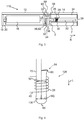
- Figure 7 shows the wick 30 of the exemplary embodiments of Figures 1 to 3 and 6 in a side view.
- the wick 30 is shown as a single wick.
- the wick may be the J-shaped wick of the exemplary embodiment of Figure 4 , or a U-shaped wick with two sections 68, 70 with the same length being folded onto each other.
- the heating wire 40 comprises the first section 44, the second section 46 and optionally the third section 54.
- the second section 46 and the third section 54 are wound around the wick 30 tighter than the first section 44.
- the second section 46 and the third section 54 are wound tight around the wick 30 in order to compress the wick 30, thereby affixing the heating wire 40 to the wick 30, e.g. by a force fit. Due to the tight winding, the wick 30 may be compressed more by the second section 46 and by the third section 54 than by the first section 44.
- the wick 30 may comprise at least one compressed section P1 and optionally two compressed sections P2 and a less or even not compressed section P0 between the compressed sections P1, P2.
- the first section 44 of the heating wire 40 is at least sectionwise of even completely coiled around the less or not compressed section P0 of the wick 30.
- the second section 46 and/or the third section 54 are each coiled around one of the compressed sections P1, P2.
- the second section 46 and/or the third section 54 may form at least one winding or a plurality of windings that are coiled tighter around the wick 30 than the first section 44 of the heating wire 40.
- the second section 46 may form at least one winding or a plurality of first windings 48 and the third section 54 may form at least one winding or a plurality of last windings50. For example, between two and six and e.g. three, four or five windings of the first and/or of the second section 44, 54 compress the wick 30 more than the first section 44 of the heating wire 40.
- the wick shown in Figure 7 is J- or U-shaped.
- a puff detector (utilizing an airflow sensor) for detecting a user puffing on a device could be provided and the puff detector could be arranged to initiate the activation of an atomizer when a user puffed on the device
- the puff detector could be replaced by a push button and a user could cause an atomizer to activate by pressing on the button.
- other means for activating the device could be provided.
- the atomizer has a heating wire that is at least section-wise formed as a heating coil comprising a plurality of windings.
- the heating wire comprises a first section and a second section.
- the electrical resistance per length unit of the first section differs from the electrical resistance per length unit of the second section, such that heat generated by the heating wire can be generated at a pre-determined position and less or even no heat is generated by the heating wire at a position, where no heat is required for the operation of the atomizer and in particular for atomizing or vaporizing liquid.
- the length unit is measured along the heating wire.
- the heating coil has a first winding, a last winding and at least one inner winding between the first winding and the last winding, wherein the at least one inner winding comprises the first section, the first winding comprises the second section, and the last winding comprises a third section, wherein the electrical resistance per length unit of the third section corresponds to the electrical resistance per length unit of the second section.
- a cartomizer for an electronic smoking device comprising an atomizer and a liquid reservoir.
- the atomizer of such a cartomizer may be an atomizer as explained above and in the following.
- the cartomizer may be designated as a clearomizer.
- liquid to be atomized within the liquid reservoir, only liquid to be atomized or a sponge-like material containing the liquid to be atomized may be present.
- an electronic smoking device comprising an atomizer and a liquid reservoir.
- the atomizer of such an electronic smoking device may be the atomizer described above and in the following.
- An advantage may be that essentially only an inner section of the heating coil is used for generating atomizing or vaporizing heat, whereas outer parts of the coil generate no or less heat.
- lead wires that interconnect the heating coil with a power supply and in particular with the control electronics of an electronic smoking device may not unduly heat up and prevent that an undue amount of heat is transmitted to the electronics or other parts of the electronic smoking device.
- the electrical resistance per length unit of the first section may be higher than the electrical resistance per length unit of the second section.
- an advantage may be that essentially only the first section generates heat required for the operation of the atomizer and in particular to atomize or to vaporize liquid, whereas the second section generates less or even a negligible quantity of heat when the atomizer is operated and heating current is led through the heating wire.
- the electrical resistance per length unit of the second section may be negligible compared to the electrical resistance per length unit of the first section such that over 90%, over 95% or even over 99% of the heat generated by the heating coil is generated by the first section.
- the negligible electrical resistance per length unit of the first section may correspond to the electrical resistance per length unit of the second section multiplied by a factor of at least 10 or between 10 and 1000 and for instance 100, 250, 500 or 750 or even more.
- a possible advantage of such a resistance per length unit ratio may be that essentially only the first section contributes to the atomizing or vaporizing of the liquid, and the second section does not generate any or, compared to the first section, very little heat. Hence, electrical energy used to produce heating energy with the atomizer for vaporizing liquid is efficiently used essentially only in the first section.
- the diameter of the heating wire of the first section may be less than the diameter of the heating wire of the second section.
- An advantage of such a heating wire may be that it can be easily produced from a standard wire, whose first section is thinned compared to the second section, wherein the first section and the second section may be made of the same material.
- the first section may be made of a first material and the second section may be made of a second material.
- the first material may have an electrical conductivity that differs from the electrical conductivity of the second material. Thinning a wire, namely, may have the disadvantage that the thinned first section may be mechanically weak and may deteriorate faster than an unthinned section of the heating wire during operation of the atomizer.
- the electrical conductivities of the first and the second sections can be better controlled and pre-selected when using different materials compared to using different diameters for generating the different electrical conductivities.
- the ratio between the electrical conductivities may be higher in case different materials and optionally different diameters are used.
- the electrical conductivity preferably has the unit siemens or Mho.
- the first material is nichrome
- the second material may be copper or aluminum or an alloy with a lower resistance per length unit.
- the first section and the second section may be formed continuously or may be interconnected by a material fit, e.g. by welding or soldering.
- a material fit e.g. by welding or soldering.
- the at least one inner winding may even consist of the first section.
- the second section may at least section-wise form the first winding and optionally at least a section of at least one winding following the first winding.
- at least a section of the third section may form the last winding and optionally at least a section of at least one winding preceding the last winding.
- the first winding and one of the lead wires may be formed of the second section.
- the last winding and another one of the lead wires may be formed of the third section.
- the electrical, material and/or geometrical properties, such as the diameter, of the third winding may correspond to the electrical, material and/or geometrical properties, such as the diameter, of the second winding.
- the heating coil may comprise a plurality of inner windings that consist of the first section.
- an advantage of such a heating coil may be that the heating coil emits heat over a larger area, this area essentially corresponding to a lateral surface of a cylinder that can be placed inside of the heating coil, the length of the cylinder being limited by the plurality of inner windings, such that isolated heat spots are prevented and a sufficient amount of liquid can be atomized or vaporized.
- the second section and/or the third section of the heating wire may be wound around the wick tighter than the first section.
- the second section and/or the third section may be wound tight around the wick in order to compress the wick, thereby affixing the heating wire to the wick, e.g. by a force fit. Due to the tight winding, the wick may be more compressed by the second section and/or the third section than by the first section.
- the wick may comprise compressed sections and a less or even not compressed section between the compressed sections.
- the first section of the heating wire is at least sectionwise of even completely coiled around the less or not compressed section of the wick and the second section and/or the third section are each at least sectionwise coiled around one of the compressed sections.
- the second section and/or the third section may form at least one winding or a plurality of windings that are coiled tighter around the wick than the windings of the first section of the heating wire. For example, between two and six and e.g. three, four or five windings of the first and/or of the second section compress the wick more than the first section of the heating wire.
- the second section and/or the third section may extend onto the less or not compressed section of the wick for up to one or more windings.
- An advantage of this embodiment may be that the heating wire is securely fixed to the wick without the need for separate fixing elements, thereby reducing structural complexity and facilitating production of the atomizer.
- the electronic smoking device may be used to apply medical materials to be inhaled.
- medical materials to be inhaled Such inhalants can be atomized or vaporized and inhaled like the liquid and may even be provided in the liquid reservoir.
- the electronic smoking device is deemed to be used to providing vapour containing medicine to be inhaled, and e.g. in case the medicine to be inhaled is present in the liquid reservoir, the medicine to be inhaled may be designated as medical device and/or inhaler.
- An advantage of such a device with the heating wire that comprises the first and the second section may be that medical materials are prevented from being overheated due to the concentrated generation of heat.
Claims (9)
- Atomiseur (26, 126) pour un dispositif de cigarette électronique (10, 110, 210) avec un fil chauffant (40) qui est formé comme un serpentin de chauffage (28) au moins par section, comprenant une pluralité d'enroulements (42), le fil chauffant (40) comprenant une première section (44) et une deuxième section (46), la résistance électrique par unité de longueur de la première section (44) étant différente de la résistance électrique par unité de longueur de la deuxième section (46), caractérisé en ce que le serpentin de chauffage (28) a un premier enroulement (48), un dernier enroulement (50) et au moins un enroulement intérieur (52) entre le premier enroulement (48) et le dernier enroulement (50), l'au moins un enroulement intérieur (52) comprenant la première section (44), le premier enroulement (48) comprenant la deuxième section (46) et le dernier enroulement (50) comprenant une troisième section (54), la résistance électrique par unité de longueur de la troisième section (54) correspondant à la résistance électrique par unité de longueur de la deuxième section (46).
- Atomiseur (26, 126) selon la revendication 1, caractérisé en ce que la résistance électrique par unité de longueur de la première section (44) est supérieure à la résistance électrique par unité de longueur de la deuxième section (46).
- Atomiseur (26, 126) selon la revendication 1 ou 2, caractérisé en ce que la résistance électrique par unité de longueur de la première section (44) correspond à la résistance électrique par unité de longueur de la deuxième section (46) multipliée par un facteur d'au moins 10.
- Atomiseur (26, 126) selon l'une quelconque des revendications 1 à 3, caractérisé en ce que le diamètre (D1) du fil chauffant (40) de la première section (44) est inférieur au diamètre (D2) du fil chauffant (40) de la deuxième section (46).
- Atomiseur (26, 126) selon l'une quelconque des revendications 1 à 4, caractérisé en ce que la première section (44) est composée d'un premier matériau, et en ce que la deuxième section (46) est composée d'un deuxième matériau, le premier matériau ayant une conductivité électrique qui est différente de la conductivité électrique du deuxième matériau.
- Atomiseur (26, 126) selon l'une quelconque des revendications 1 à 5, caractérisé en ce que la première section (44) et la deuxième section (46) sont formées de façon continue ou sont interconnectées par liaison de matériaux.
- Atomiseur (26, 126) selon l'une quelconque des revendications 1 à 6, caractérisé en ce que le serpentin de chauffage (28) comprend une pluralité d'enroulements intérieurs (52) qui sont constitués par la première section (44).
- Cartomiseur (74) pour un dispositif de cigarette électronique (10, 110, 210), avec un atomiseur (26, 126), caractérisé en ce que l'atomiseur (26, 126) est un atomiseur selon l'une quelconque des revendications 1 à 7.
- Dispositif de cigarette électronique (10, 110, 210), avec un atomiseur (26, 126), caractérisé en ce que l'atomiseur (26, 126) est un atomiseur (26, 126) selon l'une quelconque des revendications 1 à 7.
Priority Applications (2)
| Application Number | Priority Date | Filing Date | Title |
|---|---|---|---|
| EP17176368.3A EP3248488B1 (fr) | 2015-06-25 | 2015-06-25 | Dispositif à fumer électronique et atomiseur |
| ES17176368T ES2887242T3 (es) | 2015-06-25 | 2015-06-25 | Dispositivo electrónico para fumar y atomizador |
Applications Claiming Priority (2)
| Application Number | Priority Date | Filing Date | Title |
|---|---|---|---|
| EP17176368.3A EP3248488B1 (fr) | 2015-06-25 | 2015-06-25 | Dispositif à fumer électronique et atomiseur |
| EP15173933.1A EP3108759B1 (fr) | 2015-06-25 | 2015-06-25 | Dispositif a fumer electronique et atomiseur |
Related Parent Applications (2)
| Application Number | Title | Priority Date | Filing Date |
|---|---|---|---|
| EP15173933.1A Division EP3108759B1 (fr) | 2015-06-25 | 2015-06-25 | Dispositif a fumer electronique et atomiseur |
| EP15173933.1A Division-Into EP3108759B1 (fr) | 2015-06-25 | 2015-06-25 | Dispositif a fumer electronique et atomiseur |
Publications (2)
| Publication Number | Publication Date |
|---|---|
| EP3248488A1 EP3248488A1 (fr) | 2017-11-29 |
| EP3248488B1 true EP3248488B1 (fr) | 2021-04-07 |
Family
ID=53488266
Family Applications (2)
| Application Number | Title | Priority Date | Filing Date |
|---|---|---|---|
| EP15173933.1A Active EP3108759B1 (fr) | 2015-06-25 | 2015-06-25 | Dispositif a fumer electronique et atomiseur |
| EP17176368.3A Active EP3248488B1 (fr) | 2015-06-25 | 2015-06-25 | Dispositif à fumer électronique et atomiseur |
Family Applications Before (1)
| Application Number | Title | Priority Date | Filing Date |
|---|---|---|---|
| EP15173933.1A Active EP3108759B1 (fr) | 2015-06-25 | 2015-06-25 | Dispositif a fumer electronique et atomiseur |
Country Status (7)
| Country | Link |
|---|---|
| US (1) | US10701974B2 (fr) |
| EP (2) | EP3108759B1 (fr) |
| CN (1) | CN107920595B (fr) |
| ES (1) | ES2887242T3 (fr) |
| GB (1) | GB2539720A (fr) |
| PL (1) | PL3108759T3 (fr) |
| WO (1) | WO2016207357A1 (fr) |
Families Citing this family (41)
| Publication number | Priority date | Publication date | Assignee | Title |
|---|---|---|---|---|
| US10244793B2 (en) | 2005-07-19 | 2019-04-02 | Juul Labs, Inc. | Devices for vaporization of a substance |
| US10279934B2 (en) | 2013-03-15 | 2019-05-07 | Juul Labs, Inc. | Fillable vaporizer cartridge and method of filling |
| US10058129B2 (en) | 2013-12-23 | 2018-08-28 | Juul Labs, Inc. | Vaporization device systems and methods |
| USD842536S1 (en) | 2016-07-28 | 2019-03-05 | Juul Labs, Inc. | Vaporizer cartridge |
| US10076139B2 (en) | 2013-12-23 | 2018-09-18 | Juul Labs, Inc. | Vaporizer apparatus |
| US20160366947A1 (en) | 2013-12-23 | 2016-12-22 | James Monsees | Vaporizer apparatus |
| KR102256889B1 (ko) | 2013-12-23 | 2021-05-31 | 쥴 랩스, 인크. | 기화 디바이스 시스템 및 방법 |
| US10159282B2 (en) | 2013-12-23 | 2018-12-25 | Juul Labs, Inc. | Cartridge for use with a vaporizer device |
| USD825102S1 (en) | 2016-07-28 | 2018-08-07 | Juul Labs, Inc. | Vaporizer device with cartridge |
| KR102627987B1 (ko) | 2014-12-05 | 2024-01-22 | 쥴 랩스, 인크. | 교정된 투여량 제어 |
| US10588350B2 (en) * | 2015-05-04 | 2020-03-17 | Fontem Holdings 1 B.V. | Liquid guiding structure, coil-less heating element and power management unit for electronic cigarettes |
| JP6971964B2 (ja) | 2015-07-10 | 2021-11-24 | ジュール・ラブズ・インコーポレイテッドJuul Labs, Inc. | 芯のない蒸発装置と方法 |
| DE202017007467U1 (de) | 2016-02-11 | 2021-12-08 | Juul Labs, Inc. | Befüllbare Verdampferkartusche |
| EP3419443A4 (fr) | 2016-02-11 | 2019-11-20 | Juul Labs, Inc. | Cartouches fixées de manière sure pour des dispositifs de vaporisation |
| US10405582B2 (en) | 2016-03-10 | 2019-09-10 | Pax Labs, Inc. | Vaporization device with lip sensing |
| ITUA20162410A1 (it) * | 2016-04-08 | 2017-10-08 | Gd Spa | Metodo ed unità di ispezione di un organo riscaldante per sigaretta elettronica. |
| USD849996S1 (en) | 2016-06-16 | 2019-05-28 | Pax Labs, Inc. | Vaporizer cartridge |
| USD851830S1 (en) | 2016-06-23 | 2019-06-18 | Pax Labs, Inc. | Combined vaporizer tamp and pick tool |
| USD836541S1 (en) | 2016-06-23 | 2018-12-25 | Pax Labs, Inc. | Charging device |
| USD848057S1 (en) | 2016-06-23 | 2019-05-07 | Pax Labs, Inc. | Lid for a vaporizer |
| GB201616430D0 (en) | 2016-09-28 | 2016-11-09 | Nicoventures Holdings Limited | Liquid storage tank for a vapour provision system |
| US10701976B2 (en) | 2016-12-12 | 2020-07-07 | VMR Products, LLC | Vaporizer cartridge |
| GB201704674D0 (en) * | 2017-03-24 | 2017-05-10 | Nicoventures Holdings Ltd | Aerosol source for a vapour provision system |
| GB201707050D0 (en) | 2017-05-03 | 2017-06-14 | British American Tobacco Investments Ltd | Data communication |
| GB201713681D0 (en) * | 2017-08-25 | 2017-10-11 | Nicoventures Holdings Ltd | Vapour provision systems |
| GB201714564D0 (en) * | 2017-09-11 | 2017-10-25 | British American Tobacco Investments Ltd | Heater for aerosol generating device and device |
| USD887632S1 (en) | 2017-09-14 | 2020-06-16 | Pax Labs, Inc. | Vaporizer cartridge |
| EP3494811B1 (fr) * | 2017-12-07 | 2021-03-17 | Fontem Holdings 1 B.V. | Dispositif à fumer électronique doté d'un élément chauffant présentant une surface modifiée |
| GB201722278D0 (en) | 2017-12-29 | 2018-02-14 | British American Tobacco Investments Ltd | Device identification and method |
| GB201801143D0 (en) | 2018-01-24 | 2018-03-07 | Nicoventures Trading Ltd | vapour provision apparatus and systems |
| GB201801144D0 (en) | 2018-01-24 | 2018-03-07 | Nicoventures Trading Ltd | Aerosol source for a vapour provision system |
| GB201801145D0 (en) | 2018-01-24 | 2018-03-07 | Nicoventures Trading Ltd | Vapour provision systems |
| JP2021532782A (ja) | 2018-07-31 | 2021-12-02 | ジュール・ラブズ・インコーポレイテッドJuul Labs, Inc. | カートリッジベースの非燃焼加熱式気化器 |
| DE102018007981B3 (de) * | 2018-10-10 | 2020-03-12 | W. O. M. World of Medicine GmbH | Wasserreservoir für eine Vorrichtung zur Gasbefeuchtung in der Laparoskopie |
| EP3876761A1 (fr) | 2018-11-05 | 2021-09-15 | Juul Labs, Inc. | Cartouches pour dispositifs de vaporisation |
| CN109349680A (zh) * | 2018-11-15 | 2019-02-19 | 深圳市合元科技有限公司 | 多孔发热体、包含多孔发热体的雾化器及多孔体制备方法 |
| US20200245695A1 (en) * | 2019-02-03 | 2020-08-06 | Avanzato Technology Corp. | Vaporization device having a wick and coil assembly |
| EP3935975A4 (fr) * | 2019-03-08 | 2022-10-12 | Japan Tobacco Inc. | Cartouche de dispositif d'inhalation et dispositif d'inhalation la comprenant |
| KR102283442B1 (ko) * | 2019-06-04 | 2021-07-29 | 주식회사 케이티앤지 | 증기화기 및 이를 포함하는 에어로졸 생성 장치 |
| CN110586807B (zh) * | 2019-09-26 | 2021-06-15 | 深圳雷炎科技有限公司 | 一种环保型电热器件自动化加工设备 |
| US11839239B2 (en) | 2020-08-12 | 2023-12-12 | DES Products Ltd. | Adjustable airflow cartridge for electronic vaporizer |
Family Cites Families (22)
| Publication number | Priority date | Publication date | Assignee | Title |
|---|---|---|---|---|
| JP4753395B2 (ja) * | 2009-12-04 | 2011-08-24 | 和彦 清水 | 無煙喫煙治具 |
| CN202068933U (zh) | 2011-05-24 | 2011-12-14 | 陈文� | 一种电子烟双发热丝雾化器 |
| KR200456814Y1 (ko) * | 2011-09-21 | 2011-11-21 | (주)잔티아시아 | 조립식 연소부를 갖는 전자담배 |
| US9282772B2 (en) * | 2012-01-31 | 2016-03-15 | Altria Client Services Llc | Electronic vaping device |
| EP2816913B1 (fr) * | 2012-02-22 | 2019-01-09 | Altria Client Services LLC | Article fumeur électronique et élément chauffant amélioré |
| CN202873795U (zh) * | 2012-10-23 | 2013-04-17 | 深圳市合元科技有限公司 | 电子烟用雾化装置及电子烟 |
| CN102894485B (zh) * | 2012-10-23 | 2015-04-01 | 深圳市合元科技有限公司 | 电子烟用雾化装置、雾化器及电子烟 |
| RS55259B1 (sr) * | 2012-12-28 | 2017-02-28 | Philip Morris Products Sa | Grejni sklop za sistem za proizvodnju aerosola |
| CN103987142A (zh) * | 2013-02-08 | 2014-08-13 | 刘秋明 | 一种发热元件、电子烟以及形成发热元件的方法 |
| US9993023B2 (en) * | 2013-02-22 | 2018-06-12 | Altria Client Services Llc | Electronic smoking article |
| KR102282683B1 (ko) * | 2013-03-14 | 2021-07-27 | 레이 스트라티직 홀딩스, 인크. | 에어로졸 송달 장치용 분무기 및 관련 입력부, 에어로졸 생산 조립체, 및 분무기 형성 방법 |
| US9918495B2 (en) * | 2014-02-28 | 2018-03-20 | Rai Strategic Holdings, Inc. | Atomizer for an aerosol delivery device and related input, aerosol production assembly, cartridge, and method |
| EP4018859A1 (fr) * | 2013-03-15 | 2022-06-29 | RAI Strategic Holdings, Inc. | Éléments chauffants formés à partir d'une feuille de matériau, entrées et procédés pour la production de pulvérisateurs, cartouche pour un dispositif de distribution d'aérosol et procédé pour assembler une cartouche pour un article à fumer |
| US9629394B2 (en) * | 2013-04-09 | 2017-04-25 | Alan Benet Aronie | Portable vaporizer with central pin heater having heat diffuser-mixer blades |
| CN203329913U (zh) * | 2013-05-07 | 2013-12-11 | 深圳市合元科技有限公司 | 一种有棉雾化器及电子烟 |
| CN203789147U (zh) | 2013-10-20 | 2014-08-27 | 红塔烟草(集团)有限责任公司 | 一种能调节烟雾量的智能电加热卷烟用加热器 |
| US9955726B2 (en) * | 2014-05-23 | 2018-05-01 | Rai Strategic Holdings, Inc. | Sealed cartridge for an aerosol delivery device and related assembly method |
| CN204146334U (zh) | 2014-09-22 | 2015-02-11 | 深圳市合元科技有限公司 | 电子吸烟装置及可与雾化器组装成电子吸烟装置的盒体 |
| WO2016061859A1 (fr) * | 2014-10-21 | 2016-04-28 | 朱晓春 | Composant chauffant pour atomiseur de cigarette électronique |
| CN104544568B (zh) | 2014-12-25 | 2017-12-01 | 东莞市哈维电子科技有限公司 | 一种可调节电阻和气流大小的电子烟雾化器 |
| CN104540246A (zh) * | 2015-01-04 | 2015-04-22 | 深圳市亿斯恩科技有限公司 | 一种雾化器用发热丝 |
| US10194694B2 (en) * | 2016-01-05 | 2019-02-05 | Rai Strategic Holdings, Inc. | Aerosol delivery device with improved fluid transport |
-
2015
- 2015-06-25 ES ES17176368T patent/ES2887242T3/es active Active
- 2015-06-25 EP EP15173933.1A patent/EP3108759B1/fr active Active
- 2015-06-25 PL PL15173933T patent/PL3108759T3/pl unknown
- 2015-06-25 EP EP17176368.3A patent/EP3248488B1/fr active Active
- 2015-07-13 GB GB1512184.1A patent/GB2539720A/en not_active Withdrawn
-
2016
- 2016-06-24 CN CN201680047328.6A patent/CN107920595B/zh active Active
- 2016-06-24 US US15/739,613 patent/US10701974B2/en active Active
- 2016-06-24 WO PCT/EP2016/064678 patent/WO2016207357A1/fr active Application Filing
Non-Patent Citations (1)
| Title |
|---|
| None * |
Also Published As
| Publication number | Publication date |
|---|---|
| CN107920595B (zh) | 2021-06-04 |
| PL3108759T3 (pl) | 2020-05-18 |
| GB2539720A (en) | 2016-12-28 |
| EP3248488A1 (fr) | 2017-11-29 |
| CN107920595A (zh) | 2018-04-17 |
| GB201512184D0 (en) | 2015-08-19 |
| US10701974B2 (en) | 2020-07-07 |
| ES2887242T3 (es) | 2021-12-22 |
| US20180177236A1 (en) | 2018-06-28 |
| EP3108759A1 (fr) | 2016-12-28 |
| WO2016207357A1 (fr) | 2016-12-29 |
| EP3108759B1 (fr) | 2019-11-20 |
Similar Documents
| Publication | Publication Date | Title |
|---|---|---|
| EP3248488B1 (fr) | Dispositif à fumer électronique et atomiseur | |
| EP3135135B1 (fr) | Dispositif à fumer électronique avec réservoir de liquide/partie de mèche | |
| US10750786B2 (en) | Electronic smoking device with secondary heating element | |
| US10602773B2 (en) | Mouth piece of an electronic smoking device having a tempering element | |
| EP3069620B1 (fr) | Dispositif à fumer électronique | |
| EP3114946B1 (fr) | Dispositif à fumer électronique avec ouverture de sortie de vapeur | |
| EP3042579A1 (fr) | Dispositif à fumer électronique | |
| EP3075271A1 (fr) | Dispositif à fumer électronique avec un réservoir de liquide comprenant un actionneur | |
| US20230180829A1 (en) | Electronic smoking device | |
| US20210037883A1 (en) | Electronic smoking device with liquid pump | |
| US11844375B2 (en) | Electronic smoking device with capillary element |
Legal Events
| Date | Code | Title | Description |
|---|---|---|---|
| PUAI | Public reference made under article 153(3) epc to a published international application that has entered the european phase |
Free format text: ORIGINAL CODE: 0009012 |
|
| STAA | Information on the status of an ep patent application or granted ep patent |
Free format text: STATUS: THE APPLICATION HAS BEEN PUBLISHED |
|
| AC | Divisional application: reference to earlier application |
Ref document number: 3108759 Country of ref document: EP Kind code of ref document: P |
|
| AK | Designated contracting states |
Kind code of ref document: A1 Designated state(s): AL AT BE BG CH CY CZ DE DK EE ES FI FR GB GR HR HU IE IS IT LI LT LU LV MC MK MT NL NO PL PT RO RS SE SI SK SM TR |
|
| AX | Request for extension of the european patent |
Extension state: BA ME |
|
| STAA | Information on the status of an ep patent application or granted ep patent |
Free format text: STATUS: REQUEST FOR EXAMINATION WAS MADE |
|
| 17P | Request for examination filed |
Effective date: 20180525 |
|
| RBV | Designated contracting states (corrected) |
Designated state(s): AL AT BE BG CH CY CZ DE DK EE ES FI FR GB GR HR HU IE IS IT LI LT LU LV MC MK MT NL NO PL PT RO RS SE SI SK SM TR |
|
| REG | Reference to a national code |
Ref country code: DE Ref legal event code: R079 Ref document number: 602015067983 Country of ref document: DE Free format text: PREVIOUS MAIN CLASS: A24F0047000000 Ipc: A24F0040460000 |
|
| GRAP | Despatch of communication of intention to grant a patent |
Free format text: ORIGINAL CODE: EPIDOSNIGR1 |
|
| RIC1 | Information provided on ipc code assigned before grant |
Ipc: A24F 40/10 20200101ALN20201008BHEP Ipc: A61M 15/06 20060101ALI20201008BHEP Ipc: A61M 16/00 20060101ALN20201008BHEP Ipc: A24F 40/46 20200101AFI20201008BHEP Ipc: A61M 11/04 20060101ALI20201008BHEP Ipc: A61M 15/00 20060101ALN20201008BHEP |
|
| STAA | Information on the status of an ep patent application or granted ep patent |
Free format text: STATUS: GRANT OF PATENT IS INTENDED |
|
| RIC1 | Information provided on ipc code assigned before grant |
Ipc: A61M 16/00 20060101ALN20201019BHEP Ipc: A24F 40/46 20200101AFI20201019BHEP Ipc: A61M 15/00 20060101ALN20201019BHEP Ipc: A61M 11/04 20060101ALI20201019BHEP Ipc: A61M 15/06 20060101ALI20201019BHEP Ipc: A24F 40/10 20200101ALN20201019BHEP |
|
| INTG | Intention to grant announced |
Effective date: 20201112 |
|
| GRAS | Grant fee paid |
Free format text: ORIGINAL CODE: EPIDOSNIGR3 |
|
| GRAA | (expected) grant |
Free format text: ORIGINAL CODE: 0009210 |
|
| STAA | Information on the status of an ep patent application or granted ep patent |
Free format text: STATUS: THE PATENT HAS BEEN GRANTED |
|
| AC | Divisional application: reference to earlier application |
Ref document number: 3108759 Country of ref document: EP Kind code of ref document: P |
|
| AK | Designated contracting states |
Kind code of ref document: B1 Designated state(s): AL AT BE BG CH CY CZ DE DK EE ES FI FR GB GR HR HU IE IS IT LI LT LU LV MC MK MT NL NO PL PT RO RS SE SI SK SM TR |
|
| REG | Reference to a national code |
Ref country code: GB Ref legal event code: FG4D |
|
| REG | Reference to a national code |
Ref country code: AT Ref legal event code: REF Ref document number: 1378530 Country of ref document: AT Kind code of ref document: T Effective date: 20210415 Ref country code: CH Ref legal event code: EP |
|
| REG | Reference to a national code |
Ref country code: DE Ref legal event code: R096 Ref document number: 602015067983 Country of ref document: DE |
|
| REG | Reference to a national code |
Ref country code: IE Ref legal event code: FG4D |
|
| REG | Reference to a national code |
Ref country code: LT Ref legal event code: MG9D |
|
| REG | Reference to a national code |
Ref country code: NL Ref legal event code: MP Effective date: 20210407 Ref country code: AT Ref legal event code: MK05 Ref document number: 1378530 Country of ref document: AT Kind code of ref document: T Effective date: 20210407 |
|
| PG25 | Lapsed in a contracting state [announced via postgrant information from national office to epo] |
Ref country code: NL Free format text: LAPSE BECAUSE OF FAILURE TO SUBMIT A TRANSLATION OF THE DESCRIPTION OR TO PAY THE FEE WITHIN THE PRESCRIBED TIME-LIMIT Effective date: 20210407 Ref country code: HR Free format text: LAPSE BECAUSE OF FAILURE TO SUBMIT A TRANSLATION OF THE DESCRIPTION OR TO PAY THE FEE WITHIN THE PRESCRIBED TIME-LIMIT Effective date: 20210407 Ref country code: AT Free format text: LAPSE BECAUSE OF FAILURE TO SUBMIT A TRANSLATION OF THE DESCRIPTION OR TO PAY THE FEE WITHIN THE PRESCRIBED TIME-LIMIT Effective date: 20210407 Ref country code: BG Free format text: LAPSE BECAUSE OF FAILURE TO SUBMIT A TRANSLATION OF THE DESCRIPTION OR TO PAY THE FEE WITHIN THE PRESCRIBED TIME-LIMIT Effective date: 20210707 Ref country code: FI Free format text: LAPSE BECAUSE OF FAILURE TO SUBMIT A TRANSLATION OF THE DESCRIPTION OR TO PAY THE FEE WITHIN THE PRESCRIBED TIME-LIMIT Effective date: 20210407 Ref country code: LT Free format text: LAPSE BECAUSE OF FAILURE TO SUBMIT A TRANSLATION OF THE DESCRIPTION OR TO PAY THE FEE WITHIN THE PRESCRIBED TIME-LIMIT Effective date: 20210407 |
|
| PG25 | Lapsed in a contracting state [announced via postgrant information from national office to epo] |
Ref country code: GR Free format text: LAPSE BECAUSE OF FAILURE TO SUBMIT A TRANSLATION OF THE DESCRIPTION OR TO PAY THE FEE WITHIN THE PRESCRIBED TIME-LIMIT Effective date: 20210708 Ref country code: IS Free format text: LAPSE BECAUSE OF FAILURE TO SUBMIT A TRANSLATION OF THE DESCRIPTION OR TO PAY THE FEE WITHIN THE PRESCRIBED TIME-LIMIT Effective date: 20210807 Ref country code: LV Free format text: LAPSE BECAUSE OF FAILURE TO SUBMIT A TRANSLATION OF THE DESCRIPTION OR TO PAY THE FEE WITHIN THE PRESCRIBED TIME-LIMIT Effective date: 20210407 Ref country code: PT Free format text: LAPSE BECAUSE OF FAILURE TO SUBMIT A TRANSLATION OF THE DESCRIPTION OR TO PAY THE FEE WITHIN THE PRESCRIBED TIME-LIMIT Effective date: 20210809 Ref country code: PL Free format text: LAPSE BECAUSE OF FAILURE TO SUBMIT A TRANSLATION OF THE DESCRIPTION OR TO PAY THE FEE WITHIN THE PRESCRIBED TIME-LIMIT Effective date: 20210407 Ref country code: NO Free format text: LAPSE BECAUSE OF FAILURE TO SUBMIT A TRANSLATION OF THE DESCRIPTION OR TO PAY THE FEE WITHIN THE PRESCRIBED TIME-LIMIT Effective date: 20210707 Ref country code: SE Free format text: LAPSE BECAUSE OF FAILURE TO SUBMIT A TRANSLATION OF THE DESCRIPTION OR TO PAY THE FEE WITHIN THE PRESCRIBED TIME-LIMIT Effective date: 20210407 Ref country code: RS Free format text: LAPSE BECAUSE OF FAILURE TO SUBMIT A TRANSLATION OF THE DESCRIPTION OR TO PAY THE FEE WITHIN THE PRESCRIBED TIME-LIMIT Effective date: 20210407 |
|
| REG | Reference to a national code |
Ref country code: ES Ref legal event code: FG2A Ref document number: 2887242 Country of ref document: ES Kind code of ref document: T3 Effective date: 20211222 |
|
| REG | Reference to a national code |
Ref country code: DE Ref legal event code: R097 Ref document number: 602015067983 Country of ref document: DE |
|
| PG25 | Lapsed in a contracting state [announced via postgrant information from national office to epo] |
Ref country code: SM Free format text: LAPSE BECAUSE OF FAILURE TO SUBMIT A TRANSLATION OF THE DESCRIPTION OR TO PAY THE FEE WITHIN THE PRESCRIBED TIME-LIMIT Effective date: 20210407 Ref country code: SK Free format text: LAPSE BECAUSE OF FAILURE TO SUBMIT A TRANSLATION OF THE DESCRIPTION OR TO PAY THE FEE WITHIN THE PRESCRIBED TIME-LIMIT Effective date: 20210407 Ref country code: EE Free format text: LAPSE BECAUSE OF FAILURE TO SUBMIT A TRANSLATION OF THE DESCRIPTION OR TO PAY THE FEE WITHIN THE PRESCRIBED TIME-LIMIT Effective date: 20210407 Ref country code: CZ Free format text: LAPSE BECAUSE OF FAILURE TO SUBMIT A TRANSLATION OF THE DESCRIPTION OR TO PAY THE FEE WITHIN THE PRESCRIBED TIME-LIMIT Effective date: 20210407 Ref country code: DK Free format text: LAPSE BECAUSE OF FAILURE TO SUBMIT A TRANSLATION OF THE DESCRIPTION OR TO PAY THE FEE WITHIN THE PRESCRIBED TIME-LIMIT Effective date: 20210407 Ref country code: MC Free format text: LAPSE BECAUSE OF FAILURE TO SUBMIT A TRANSLATION OF THE DESCRIPTION OR TO PAY THE FEE WITHIN THE PRESCRIBED TIME-LIMIT Effective date: 20210407 Ref country code: RO Free format text: LAPSE BECAUSE OF FAILURE TO SUBMIT A TRANSLATION OF THE DESCRIPTION OR TO PAY THE FEE WITHIN THE PRESCRIBED TIME-LIMIT Effective date: 20210407 |
|
| REG | Reference to a national code |
Ref country code: CH Ref legal event code: PL |
|
| PLBE | No opposition filed within time limit |
Free format text: ORIGINAL CODE: 0009261 |
|
| STAA | Information on the status of an ep patent application or granted ep patent |
Free format text: STATUS: NO OPPOSITION FILED WITHIN TIME LIMIT |
|
| REG | Reference to a national code |
Ref country code: BE Ref legal event code: MM Effective date: 20210630 |
|
| 26N | No opposition filed |
Effective date: 20220110 |
|
| PG25 | Lapsed in a contracting state [announced via postgrant information from national office to epo] |
Ref country code: LU Free format text: LAPSE BECAUSE OF NON-PAYMENT OF DUE FEES Effective date: 20210625 |
|
| PG25 | Lapsed in a contracting state [announced via postgrant information from national office to epo] |
Ref country code: LI Free format text: LAPSE BECAUSE OF NON-PAYMENT OF DUE FEES Effective date: 20210630 Ref country code: IE Free format text: LAPSE BECAUSE OF NON-PAYMENT OF DUE FEES Effective date: 20210625 Ref country code: CH Free format text: LAPSE BECAUSE OF NON-PAYMENT OF DUE FEES Effective date: 20210630 |
|
| PG25 | Lapsed in a contracting state [announced via postgrant information from national office to epo] |
Ref country code: IS Free format text: LAPSE BECAUSE OF FAILURE TO SUBMIT A TRANSLATION OF THE DESCRIPTION OR TO PAY THE FEE WITHIN THE PRESCRIBED TIME-LIMIT Effective date: 20210807 Ref country code: AL Free format text: LAPSE BECAUSE OF FAILURE TO SUBMIT A TRANSLATION OF THE DESCRIPTION OR TO PAY THE FEE WITHIN THE PRESCRIBED TIME-LIMIT Effective date: 20210407 |
|
| PG25 | Lapsed in a contracting state [announced via postgrant information from national office to epo] |
Ref country code: BE Free format text: LAPSE BECAUSE OF NON-PAYMENT OF DUE FEES Effective date: 20210630 |
|
| PG25 | Lapsed in a contracting state [announced via postgrant information from national office to epo] |
Ref country code: HU Free format text: LAPSE BECAUSE OF FAILURE TO SUBMIT A TRANSLATION OF THE DESCRIPTION OR TO PAY THE FEE WITHIN THE PRESCRIBED TIME-LIMIT; INVALID AB INITIO Effective date: 20150625 |
|
| P01 | Opt-out of the competence of the unified patent court (upc) registered |
Effective date: 20230517 |
|
| PG25 | Lapsed in a contracting state [announced via postgrant information from national office to epo] |
Ref country code: CY Free format text: LAPSE BECAUSE OF FAILURE TO SUBMIT A TRANSLATION OF THE DESCRIPTION OR TO PAY THE FEE WITHIN THE PRESCRIBED TIME-LIMIT Effective date: 20210407 |
|
| PGFP | Annual fee paid to national office [announced via postgrant information from national office to epo] |
Ref country code: IT Payment date: 20230523 Year of fee payment: 9 Ref country code: FR Payment date: 20230523 Year of fee payment: 9 Ref country code: DE Payment date: 20230523 Year of fee payment: 9 |
|
| REG | Reference to a national code |
Ref country code: DE Ref legal event code: R081 Ref document number: 602015067983 Country of ref document: DE Owner name: FONTEM VENTURES B.V., NL Free format text: FORMER OWNER: FONTEM HOLDINGS 2 B.V., AMSTERDAM, NL |
|
| PGFP | Annual fee paid to national office [announced via postgrant information from national office to epo] |
Ref country code: GB Payment date: 20230523 Year of fee payment: 9 Ref country code: ES Payment date: 20230703 Year of fee payment: 9 |