EP3247985B1 - Improvements in torque sensors - Google Patents
Improvements in torque sensors Download PDFInfo
- Publication number
- EP3247985B1 EP3247985B1 EP16701847.2A EP16701847A EP3247985B1 EP 3247985 B1 EP3247985 B1 EP 3247985B1 EP 16701847 A EP16701847 A EP 16701847A EP 3247985 B1 EP3247985 B1 EP 3247985B1
- Authority
- EP
- European Patent Office
- Prior art keywords
- shaft
- torque sensor
- connecting element
- sleeve
- torque
- Prior art date
- Legal status (The legal status is an assumption and is not a legal conclusion. Google has not performed a legal analysis and makes no representation as to the accuracy of the status listed.)
- Active
Links
- 241000282472 Canis lupus familiaris Species 0.000 claims description 48
- 230000001419 dependent effect Effects 0.000 claims description 2
- 239000002184 metal Substances 0.000 description 4
- 238000006073 displacement reaction Methods 0.000 description 2
- 238000005553 drilling Methods 0.000 description 2
- 230000001939 inductive effect Effects 0.000 description 2
- 238000005259 measurement Methods 0.000 description 2
- 239000000853 adhesive Substances 0.000 description 1
- 230000001070 adhesive effect Effects 0.000 description 1
- 230000008878 coupling Effects 0.000 description 1
- 238000010168 coupling process Methods 0.000 description 1
- 238000005859 coupling reaction Methods 0.000 description 1
- 238000004519 manufacturing process Methods 0.000 description 1
- 230000009467 reduction Effects 0.000 description 1
- 230000004044 response Effects 0.000 description 1
Images


Classifications
-
- G—PHYSICS
- G01—MEASURING; TESTING
- G01L—MEASURING FORCE, STRESS, TORQUE, WORK, MECHANICAL POWER, MECHANICAL EFFICIENCY, OR FLUID PRESSURE
- G01L3/00—Measuring torque, work, mechanical power, or mechanical efficiency, in general
- G01L3/02—Rotary-transmission dynamometers
- G01L3/04—Rotary-transmission dynamometers wherein the torque-transmitting element comprises a torsionally-flexible shaft
- G01L3/10—Rotary-transmission dynamometers wherein the torque-transmitting element comprises a torsionally-flexible shaft involving electric or magnetic means for indicating
-
- B—PERFORMING OPERATIONS; TRANSPORTING
- B62—LAND VEHICLES FOR TRAVELLING OTHERWISE THAN ON RAILS
- B62D—MOTOR VEHICLES; TRAILERS
- B62D6/00—Arrangements for automatically controlling steering depending on driving conditions sensed and responded to, e.g. control circuits
- B62D6/08—Arrangements for automatically controlling steering depending on driving conditions sensed and responded to, e.g. control circuits responsive only to driver input torque
- B62D6/10—Arrangements for automatically controlling steering depending on driving conditions sensed and responded to, e.g. control circuits responsive only to driver input torque characterised by means for sensing or determining torque
-
- B—PERFORMING OPERATIONS; TRANSPORTING
- B62—LAND VEHICLES FOR TRAVELLING OTHERWISE THAN ON RAILS
- B62D—MOTOR VEHICLES; TRAILERS
- B62D5/00—Power-assisted or power-driven steering
- B62D5/04—Power-assisted or power-driven steering electrical, e.g. using an electric servo-motor connected to, or forming part of, the steering gear
- B62D5/0403—Power-assisted or power-driven steering electrical, e.g. using an electric servo-motor connected to, or forming part of, the steering gear characterised by constructional features, e.g. common housing for motor and gear box
-
- G—PHYSICS
- G01—MEASURING; TESTING
- G01L—MEASURING FORCE, STRESS, TORQUE, WORK, MECHANICAL POWER, MECHANICAL EFFICIENCY, OR FLUID PRESSURE
- G01L3/00—Measuring torque, work, mechanical power, or mechanical efficiency, in general
- G01L3/02—Rotary-transmission dynamometers
- G01L3/04—Rotary-transmission dynamometers wherein the torque-transmitting element comprises a torsionally-flexible shaft
- G01L3/10—Rotary-transmission dynamometers wherein the torque-transmitting element comprises a torsionally-flexible shaft involving electric or magnetic means for indicating
- G01L3/101—Rotary-transmission dynamometers wherein the torque-transmitting element comprises a torsionally-flexible shaft involving electric or magnetic means for indicating involving magnetic or electromagnetic means
- G01L3/102—Rotary-transmission dynamometers wherein the torque-transmitting element comprises a torsionally-flexible shaft involving electric or magnetic means for indicating involving magnetic or electromagnetic means involving magnetostrictive means
-
- G—PHYSICS
- G01—MEASURING; TESTING
- G01L—MEASURING FORCE, STRESS, TORQUE, WORK, MECHANICAL POWER, MECHANICAL EFFICIENCY, OR FLUID PRESSURE
- G01L3/00—Measuring torque, work, mechanical power, or mechanical efficiency, in general
- G01L3/02—Rotary-transmission dynamometers
- G01L3/04—Rotary-transmission dynamometers wherein the torque-transmitting element comprises a torsionally-flexible shaft
- G01L3/10—Rotary-transmission dynamometers wherein the torque-transmitting element comprises a torsionally-flexible shaft involving electric or magnetic means for indicating
- G01L3/101—Rotary-transmission dynamometers wherein the torque-transmitting element comprises a torsionally-flexible shaft involving electric or magnetic means for indicating involving magnetic or electromagnetic means
- G01L3/105—Rotary-transmission dynamometers wherein the torque-transmitting element comprises a torsionally-flexible shaft involving electric or magnetic means for indicating involving magnetic or electromagnetic means involving inductive means
Definitions
- This invention relates to improvements in torque sensors, particularly for use in electric power assisted steering systems. It also relates to an electrically assisted power steering system that incorporates a torque sensor.
- an electric motor applies a torque to the steering that assists the driver in turning the wheel.
- a typical column drive system this comprises a steering column shaft that is supported within a shroud.
- the shaft is connected to the steering wheel at one end and engages a gearbox at the other.
- the gearbox connects the shaft to an electric motor and also to the steered wheels of the vehicle.
- the electric motor is driven by a suitable drive circuit to apply the torque, and the drive circuit responds to a torque demand signal produced by a controller.
- a torque sensor is provided which measures the torque applied to the column shaft by the driver, or measures the torque at some other point in the system depending on the type of system produced. This torque measurement is fed into the controller and used as the basis for producing the torque demand signal. Generally speaking the higher the measured torque, the larger the value of the assistance torque.
- the assistance torque applied by the motor can also vary as a function of vehicle speed or other vehicle operating parameters. Indeed the motor can also be used to apply other torques that may be helpful in controlling the vehicle.
- torque sensors are available but commonly a torque sensor is used that works by measuring the differential angular displacement between the two ends of a torsion bar that is connected in line between the column shaft and the gearbox.
- the angular displacement can be measured using a range of different sensors, with magnetic or inductive type sensors being commonplace due to their relatively low production cost. As the sensors are well known they will not be described here in detail.
- the torque sensor is generally housed within the gearbox. By securing the motor to the gearbox housing all of the electric assistance parts of the steering system can be manufactured as a single compact unit.
- the torsion bar provides a mechanical link between the steering wheel and road wheels. To prevent damage to the torsion bar in the event that excessive torsional loads are applied (perhaps when the vehicle road wheels hit an obstacle at speed) it is known to provide drive dogs that engage to limit the amount of twist that the torsion bar will experience. This also provides a continued mechanical connection in the very unlikely event that the torsion bar fails, albeit that there will be some free play present.
- DE 42 07 668 A1 discloses a torque sensor that senses axial movement of a control sleeve for a hydraulic steering system.
- the sleeve is secured to the rotor by diametrically opposed pins which are movable in angled passages.
- the invention provides a torque sensor for use in an electric power assisted steering system comprising:
- the connecting element may comprise a pin, which may comprise an elongate element having a generally circular cross section along all or most of its length. It may be tapered from both ends towards the centre, giving a barrel like shape, tapered from one end to the other, or of generally uniform diameter along all or most of its length.
- the connecting element may include one or more circumferential grooves at spaced locations along its length which may assist the connecting element in gripping onto the bore into which it is fixed.
- the feature that the connecting element projects into may comprise an oversized bore into which a portion of the connecting element extends.
- the feature may comprise a slot that extends tangentially across an inner face of the sleeve or an outer face of the second shaft.
- the feature may comprise an oversized bore that the connecting element projects into.
- the feature where it is a bore, may extend in a plane that is orthogonal to the axis of the torsion bar, and most preferably extend radially into or away from the axis of the torsion bar.
- the connecting element may be a press fit into the bore into which it is secured, such as an interference fit. This ensures it will not fall out of the bore whilst requiring no adhesive or other fixings to hold it in place. It may be secured in the other manners, for example a threaded engagement.
- one part of the connecting element is secured in a bore in the sleeve and another part plunges into a feature in the form of an oversized bore in the second shaft.
- Each bore may extend radially towards the axis of the shafts.
- This provides for a simple assembly as the connecting element may be easily driven down into the bore in the outer shaft until it is plunged into the bore in the inner shaft.
- the end of the connecting element may be flush with the adjacent outer surface of the second shaft when in a position of use, or recessed into the second shaft or may stand slightly proud.
- the connecting element may be a press fit in a bore in the second shaft and a part of the connecting element may be located within an oversized bore in the sleeve.
- one part of the connecting element may be secured in a bore in the sleeve and another part plunges into a feature in the form of a slot that extends linearly across a part of the circumference of the second shaft. This may be formed by drilling away part of the second shaft using a drill bit that extends perpendicular to the axis of the second shaft and is spaced radially away from the axis.
- the base of the slot may be a curved, turned, groove rather than a linear slot.
- the connecting element may be press fitted into the sleeve and project loosely into the groove.
- the drive dogs comprise flats formed into the outer face of the second shaft and flats formed into the inner face of the sleeve, the flats in the rest position facing each other but spaced apart and when an excess torque is applied the flats contacting to prevent excess relative rotation.
- the first shaft, second shaft and torsion bar may all share a common axis.
- the first shaft may comprise an output shaft and the second shaft an input shaft, the angular deflection indicating means indicating the torque applied from the input shaft to the output shaft.
- the input shaft maybe connected to a steering wheel of a vehicle through a steering column shaft, and the output shaft to the road wheels through a further part of the steering gear.
- the torque sensor may be located within a housing of a gearbox.
- the gearbox housing may also support an electric motor that has a rotor that connects to the output shaft of the torque sensor through a gearset within the gearbox housing.
- the sleeve may comprise a generally cylindrical tube that fits around the torsion bar. It may be an integral part of the first shaft, for instance being formed by hollowing out the end of the first shaft to form a bore into which the torsion bar is received. In this case, the end of the second shaft may be splined to engage corresponding splines at the bottom of the bore.
- the sleeve may be a separate component secured to the first shaft by a suitable connector assembly so that it does not rotate axially relative to the first shaft.
- the sleeve need not completely surround the torsion bar. It may, for example, be one or more elongate fingers that project axially from the first shaft to a position overlapping the second shaft.
- the first and second shafts may be provided with axially extending splines extending around an end portion furthest from the torsion bar to permit connection of the torque sensor to one or more shafts along which torque is to be applied.
- the rigid connection may be by virtue of the shaft and output connector part being integrally formed, or by otherwise being securely connected.
- the torque sensor may include processing means that determines the torque from the output of the angular deflection means.
- the angular deflection indicating means may comprise one or more angular position sensors that measure the angular position of at least one of the first shaft, the second shaft or the angular deflection of the input shaft relative to the second shaft.
- the invention provides an electric power assisted steering system comprising a steering column shaft, a gearbox, an electric motor that is connected to the steering column shaft through the gearbox, a torque sensor according to the first aspect of the invention arranged so that one of the first and second shafts of the torque sensor is connected to the gearbox and the other to the steering column shaft, and a processing circuit that receives the output of the torque sensor and derives from that output a torque demand signal indicative of an assistance torque to be applied through the gearbox by the electric motor, the assistance torque acting in the same sense as the driver applied torque to reduce the effort needed to operate the steering.
- the first shaft is connected to the steering column shaft and the second shaft to the gearbox.
- the torque sensor may be an integral part of the gearbox.
- the two may share a common housing.
- the gearbox may connect the steering column shaft to the road wheels of the vehicle.
- the shaft 102 which is typically a two part telescopic shaft, is connected to the steering wheel 103 at one end and engages a gearbox 104 at the other end, down towards the feet of the driver.
- the gearbox 104 is connected to a fixed part of the vehicle and a support bracket (not shown), located between the gearbox 104 and steering wheel 103, is secured to another fixed part of the vehicle such as the bulkhead (not shown).
- the steering column shaft 102 is supported within the shroud by bearings that allow it to rotate as the driver turns the steering wheel.
- the gearbox 104 includes a reduction gearset comprising a worm and wheel that connects the shaft to the rotor of an electric motor 105.
- the gearbox 104 also connects the shaft to the road wheels 109 of the vehicle, usually through a rack and pinion assembly 117. As the steering column shaft rotates, the rack and pinion assembly 117 cause the wheels of the vehicle to turn.
- the electric motor 105 is driven by a drive circuit 110 to apply a torque to the steering column shaft.
- the motor 105 in this example is a three phase motor and the drive circuit 110 in this example comprises a bridge having an upper switch that connects a respective phase to a positive supply voltage and a lower switch, that when closed connects the phases to a negative supply voltage or ground. By opening and closing the switches in response to pulse width modulated drive signals, the current in the motor, and hence the torque, can be accurately controlled.
- the PWM control signals for the drive circuit 110 are generated by a controller 108.
- a torque sensor 107 is provided which measures the torque applied to the column shaft by the driver. This is located in the gearbox housing 106 on the input side of the gearbox 104, by which we mean the side that connects to the steering column shaft 102. As such the torque measured will be indicative of the torque applied to the column shaft 102 by the driver turning the steering wheel 103.
- This torque measurement is fed into the controller 108 and used as the basis for producing a torque demand signal.
- the controller 108 then converts this demand signal into appropriate PWM control signals for the motor 105.
- An example of such a controller 107 is taught in the applicant's earlier patent application WO/2003/105329 .
- the torque sensor 107 is shown in more detail in Figure 2 of the drawings.
- the sensor 107 is a mechanical sensor that functions by measuring the angular deflection between a first shaft 102a and a second shaft 102b which are connected together by a torsion bar 116.
- the sensor 107 is located inside the gearbox housing 106, with the first shaft 102a being coupled through a splined connection 111 to the worm and wheel gear, and the second shaft 102b through a splined coupling to the steering column shaft.
- the torsion bar 116 is surrounded by a hollow sleeve 112 that is secured at a first position to the first shaft 102a and extends along the torsion bar 116 to at least partially axially overlap the second shaft 102b.
- a first part of angular deflection indicating means 114 Connected to the overlapping end 113 of the sleeve 112 is a first part of angular deflection indicating means 114 whilst a second part 115 is connected to the second shaft 102b.
- Many angular deflection indicating means are known in the art and any one may be used as part of the present invention. However inductive angular deflection indicating means are preferred.
- the output of the angular deflection 114,115 means is a signal that represents the torque in the torsion bar 116.
- a set of drive dogs 118a which in this example are in the form of two internal flats on diametrically opposed sides of the axis sleeve.
- the second shaft 102b is provided with a set of corresponding drive dogs 118b in the form of flats on the outer surface of the shaft 102b that are also diametrically opposed.
- the two pairs of flats 118a,118b are spaced apart so that they permit a defined range of angular deflection of the torsion bar 116 but will engage each other to provide a path for torque to be transferred from the first shaft 102a to the second shaft 102b in the event of a failure of the torsion bar 116.
- the torque sensor 107 of the invention also includes a connecting element 119 which has a first part that is secured within a bore in one of the second shaft 102b and the sleeve 113.
- the connecting element is a pin 119 having a second part that extends into a feature of the other of the second shaft 102b and the sleeve 112, at zero torque across the torque sensor 107 the pin 119 being spaced circumferentially from the feature by an angular distance greater than the spacing between the drive dogs 118a, 118b and spaced from the feature in a direction along the axis of the shafts 102a, 102b that is less than the overlap of the drive dogs 118a, 118b in that direction to prevent the input and output shafts 102a, 102b moving apart in the event of failure of the torsion bar 116 by an amount that would otherwise prevent the drive dogs 118a, 118b engaging.
- Figures 4 to 19 show four alternative embodiments in more detail, each of which includes a different arrangement for the connecting element, the bore and the feature.
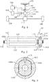
- Figure 4 is a view in cross section in a plane containing the axis of the torque sensor 207 showing the location of a connecting element 219 in a first embodiment of a torque sensor 207 within the scope of the invention
- Figure 5 is an enlarged view of the part of Figure 4 shown in a circle
- Figure 6 is a perspective view of the part of the torque sensor 207 prior to assembly.
- Figure 7 shows in perspective an end part of the sleeve 212 of the torque sensor 207.
- a connecting element 219 in the form of an elongate metal pin with a generally uniform circular cross section, is press fitted into a bore 220 in the end of the sleeve 212 where it overlaps the second shaft 202b.
- the bore 220 extends radially from the outer surface of the sleeve 212 right through the sleeve 212 towards the axis of the sleeve 212. Aligned with this bore 220 is a feature in the end of the second shaft 202b. This is also a bore 221, which extends towards the axis of the second shaft 202b, but of a larger diameter than the bore 220 in the sleeve 212. This means that the pin 219 is a loose fit in the bore 221.
- the bores 220,221 are aligned when zero torque is applied to the torsion bar 216 so that the pin 219 does not contact the side wall of the bore 221 in the second shaft 202b, and when torsion is applied that causes the pin 219 to move sideways in the bore 221 in the second shaft 202b (as the sleeve rotates around the axis of the second shaft), the pin 219 will also not contact the sides because the drive dogs (male dog 218b shown) will engage before that happens. This ensures that the pin 219 does not carry any side load during normal use and the drive dogs (male dog 218b shown) can function correctly.
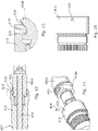
- Figures 8 to 11 are views corresponding with those of Figures 4 to 7 for a second embodiment of a torque sensor within the scope of the invention.
- This embodiment differs in that the connecting element 319 is press fitted into a bore 321 in the second shaft but loosely fits within a bore 320 in the sleeve 312 of the torque sensor 307.
- Figure 8 is a view in cross section in a plane containing the axis of the torque sensor 307 showing the location of a connecting element 319 in a first embodiment of a torque sensor 307 within the scope of the invention
- Figure 9 is an enlarged view of the part of Figure 8 shown in a circle.
- Figure 10 is a perspective view of the part of the torque sensor 307 prior to assembly.
- Figure 11 shows in perspective an end part of the sleeve 312 of the torque sensor 307.
- a connecting element 319 in the form of an elongate metal pin with a generally uniform circular cross section, is press fitted into a bore 321 in the outer surface of the second shaft 302b in the end where it overlaps the sleeve 312.
- Aligned with this bore 321 is a bore 320 in the sleeve 312 which extends radially from the outer surface of the sleeve 312 right through the sleeve 312 towards the axis of the sleeve 312, but this bore 320 is of a larger diameter than the bore 321 of the second shaft 302b.
- This means that the pin 319 is a loose fit in the bore 220.
- the bores 220,221 are aligned when zero torque is applied to the torsion bar 216 so that the pin 319 does not contact the side wall of the bore 320 in the sleeve 312, and when torsion is applied that causes the pin 319 to move sideways in the bore 320 in the sleeve 312 (as the sleeve rotates around the axis of the second shaft), the pin 319 will also not contact the sides because the drive dogs (male dog 318b shown) will engage before that happens. This ensures that the pin 319 does not carry any side load during normal use and the drive dogs (male dog 318b shown) can function correctly.
- Figures 12 to 15 are views corresponding with those of Figures 4 to 7 for a third embodiment of a torque sensor within the scope of the invention.
- one part of the connecting element is secured in a bore in the sleeve and another part that plunges into a feature in the form of a slot that extends linearly across a part of the circumference of the second shaft.
- Figure 12 is a view in cross section in a plane containing the axis of the torque sensor 407 showing the location of a connecting element 419 in a first embodiment of a torque sensor 407 within the scope of the invention
- Figure 13 is an enlarged view of the part of Figure 12 shown in a circle.
- Figure 14 is a perspective view of the part of the torque sensor 407 prior to assembly.
- Figure 15 shows in perspective an end part of the sleeve 412 of the torque sensor 407.
- a connecting element 419 in the form of an elongate metal pin with a generally uniform circular cross section, is press fitted into a bore 420 in the end of the sleeve 412 where it overlaps the second shaft 402b.
- the bore 420 extends radially from the outer surface of the sleeve 412 right through the sleeve 412 towards the axis of the sleeve 412. Aligned with this bore 420 is a feature in the end of the second shaft 402b. This feature is a slot 421 that extends linearly across a part of the circumference of the second shaft 402b.
- This may be formed by drilling away part of the second shaft using a drill bit that extends perpendicular to the axis of the second shaft and is spaced radially away from the axis.
- the pin 419 is a loose fit in the slot 421.
- the bore 420 and slot 421 are aligned when zero torque is applied to the torsion bar 416 so that the pin 419 does not contact the slot 421 in the second shaft 402b, and when torsion is applied that causes the pin 419 to move sideways in the slot 421 in the second shaft 402b (as the sleeve rotates around the axis of the second shaft), the pin 419 will also not contact the slot 421 because the drive dog (male dog 418b shown) will engage before that happens. This ensures that the pin 419 does not carry any side load during normal use and the drive dogs (male dog 418b shown) can function correctly.
- this arrangement can be inverted such that the pin is press fitted within the second shaft wherein the inner surface of the sleeve comprises a slot which contacts the pin only in the event of failure of the torsion bar.
- Figures 16 to 19 are views corresponding with those of Figures 4 to 7 for a fourth embodiment of a torque sensor within the scope of the invention.
- the second shaft comprises a slot is a curved, turned, groove rather than a linear slot.
- the connecting element is press fitted into the sleeve and project loosely into the slot.
- Figure 16 is a view in cross section in a plane containing the axis of the torque sensor 507 showing the location of a connecting element 519 in a first embodiment of a torque sensor 507 within the scope of the invention
- Figure 517 is an enlarged view of the part of Figure 16 shown in a circle
- Figure 18 is a perspective view of the part of the torque sensor 507 prior to assembly.
- Figure 19 shows in perspective an end part of the sleeve 512 of the torque sensor 507.
- a connecting element 519 in the form of an elongate metal pin with a generally uniform circular cross section, is press fitted into a bore 520 in the end of the sleeve 512 where it overlaps the second shaft 502b.
- the bore 520 extends radially from the outer surface of the sleeve 512 right through the sleeve 512 towards the axis of the sleeve 512.
- Aligned with this bore 520 is a feature in the end of the second shaft 502b. This feature is a slot 521 which is a curved, turned, groove rather than a linear slot.
- the pin 519 is a loose fit in the slot 521.
- the bore 520 and slot 521 are aligned when zero torque is applied to the torsion bar 516 so that the pin 519 does not contact the slot 521 in the second shaft 502b, and when torsion is applied that causes the pin 519 to move sideways in the slot 521 in the second shaft 502b (as the sleeve rotates around the axis of the second shaft), the pin 519 will also not contact the slot 521 because the drive dog (male dog 518b shown) will engage before that happens. This ensures that the pin 519 does not carry any side load during normal use and the drive dogs (male dog 518b shown) can function correctly.
- this arrangement can be inverted such that the pin is press fitted within the second shaft, wherein the inner surface of the sleeve comprises a grooved slot which contacts the pin only in the event of failure of the torsion bar.
Description
- This invention relates to improvements in torque sensors, particularly for use in electric power assisted steering systems. It also relates to an electrically assisted power steering system that incorporates a torque sensor.
- It is known to provide an electrically assisted power steering system in which an electric motor applies a torque to the steering that assists the driver in turning the wheel. In a typical column drive system this comprises a steering column shaft that is supported within a shroud. The shaft is connected to the steering wheel at one end and engages a gearbox at the other. The gearbox connects the shaft to an electric motor and also to the steered wheels of the vehicle. The electric motor is driven by a suitable drive circuit to apply the torque, and the drive circuit responds to a torque demand signal produced by a controller. A torque sensor is provided which measures the torque applied to the column shaft by the driver, or measures the torque at some other point in the system depending on the type of system produced. This torque measurement is fed into the controller and used as the basis for producing the torque demand signal. Generally speaking the higher the measured torque, the larger the value of the assistance torque.
- The assistance torque applied by the motor can also vary as a function of vehicle speed or other vehicle operating parameters. Indeed the motor can also be used to apply other torques that may be helpful in controlling the vehicle.
- A number of different torque sensors are available but commonly a torque sensor is used that works by measuring the differential angular displacement between the two ends of a torsion bar that is connected in line between the column shaft and the gearbox. The angular displacement can be measured using a range of different sensors, with magnetic or inductive type sensors being commonplace due to their relatively low production cost. As the sensors are well known they will not be described here in detail.
- The torque sensor is generally housed within the gearbox. By securing the motor to the gearbox housing all of the electric assistance parts of the steering system can be manufactured as a single compact unit.
- The torsion bar provides a mechanical link between the steering wheel and road wheels. To prevent damage to the torsion bar in the event that excessive torsional loads are applied (perhaps when the vehicle road wheels hit an obstacle at speed) it is known to provide drive dogs that engage to limit the amount of twist that the torsion bar will experience. This also provides a continued mechanical connection in the very unlikely event that the torsion bar fails, albeit that there will be some free play present.
- In such an event, there is a risk that the steering column shaft could move axially and separate the two ends of the torque sensor so that the dogs will not engage when the steering wheel is rotated. In the applicants earlier systems this is prevented by providing a shoulder on the steering column shaft where it enters the gearbox housing that will engage with a corresponding shoulder on the gearbox or within the shroud that supports the steering shaft. This works well but does have assembly disadvantages in that it adds additional constraints to the design of the gearbox or shroud.
-
DE 42 07 668 A1 discloses a torque sensor that senses axial movement of a control sleeve for a hydraulic steering system. The sleeve is secured to the rotor by diametrically opposed pins which are movable in angled passages. - According to a first aspect the invention provides a torque sensor for use in an electric power assisted steering system comprising:
- a first shaft, a second shaft, and a torsion bar that connects the first shaft to the second shaft,
- a hollow sleeve that is secured at a first position to the first shaft and extends along the torsion bar to at least partially axially overlap the second shaft,
- angular deflection indicating means that produce a signal that is dependent on the angular deflection of the first shaft relative to the second shaft as a torque is applied across the torque sensor that causes the torsion bar to twist,
- at least one drive dog fixed to the sleeve and at least one corresponding drive dog fixed to the second shaft, in normal operation the two dogs being offset so that they permit a defined range of angular deflection of the torsion bar but will engage each other to provide a path for torque to be transferred from the first shaft to the second shaft in the event of a failure of the torsion bar, and
- characterised by further comprising a connecting element which has a first part that is secured within a bore in one of the second shaft and the sleeve, the connecting element having a second part that extends into a feature of the other of the second shaft and the sleeve, at zero torque across the torque sensor the connecting element being spaced from the feature in a direction along the axis of the shafts that is less than the overlap of the drive dogs in that direction to prevent the shafts moving apart in the event of failure of the torsion bar by an amount that would otherwise prevent the drive dogs engaging, and wherein the connecting element and said feature are arranged such that the connecting element does not contact said feature as a result of rotation of the first part relative to the second part.
- The connecting element may comprise a pin, which may comprise an elongate element having a generally circular cross section along all or most of its length. It may be tapered from both ends towards the centre, giving a barrel like shape, tapered from one end to the other, or of generally uniform diameter along all or most of its length.
- The connecting element may include one or more circumferential grooves at spaced locations along its length which may assist the connecting element in gripping onto the bore into which it is fixed.
- The feature that the connecting element projects into may comprise an oversized bore into which a portion of the connecting element extends.
- The feature may comprise a slot that extends tangentially across an inner face of the sleeve or an outer face of the second shaft. Alternatively the feature may comprise an oversized bore that the connecting element projects into.
- The feature, where it is a bore, may extend in a plane that is orthogonal to the axis of the torsion bar, and most preferably extend radially into or away from the axis of the torsion bar.
- The connecting element may be a press fit into the bore into which it is secured, such as an interference fit. This ensures it will not fall out of the bore whilst requiring no adhesive or other fixings to hold it in place. It may be secured in the other manners, for example a threaded engagement.
- In a first preferred arrangement, one part of the connecting element is secured in a bore in the sleeve and another part plunges into a feature in the form of an oversized bore in the second shaft. Each bore may extend radially towards the axis of the shafts.
- This provides for a simple assembly as the connecting element may be easily driven down into the bore in the outer shaft until it is plunged into the bore in the inner shaft.
- The end of the connecting element may be flush with the adjacent outer surface of the second shaft when in a position of use, or recessed into the second shaft or may stand slightly proud.
- In a second preferred arrangement the connecting element may be a press fit in a bore in the second shaft and a part of the connecting element may be located within an oversized bore in the sleeve.
- In a third preferred arrangement one part of the connecting element may be secured in a bore in the sleeve and another part plunges into a feature in the form of a slot that extends linearly across a part of the circumference of the second shaft. This may be formed by drilling away part of the second shaft using a drill bit that extends perpendicular to the axis of the second shaft and is spaced radially away from the axis.
- In a fourth preferred arrangement the base of the slot may be a curved, turned, groove rather than a linear slot. The connecting element may be press fitted into the sleeve and project loosely into the groove.
- There may be one drive dog on each of the sleeve and second shaft, but preferably there may be a plurality of drive dogs associated with the sleeve and a plurality of drive dogs associated with the second shaft arranged as teeth spaced around the circumference of the sleeve and second shaft.
- In a most preferred arrangement the drive dogs comprise flats formed into the outer face of the second shaft and flats formed into the inner face of the sleeve, the flats in the rest position facing each other but spaced apart and when an excess torque is applied the flats contacting to prevent excess relative rotation.
- The first shaft, second shaft and torsion bar may all share a common axis.
- The first shaft may comprise an output shaft and the second shaft an input shaft, the angular deflection indicating means indicating the torque applied from the input shaft to the output shaft. In use the input shaft maybe connected to a steering wheel of a vehicle through a steering column shaft, and the output shaft to the road wheels through a further part of the steering gear.
- The torque sensor may be located within a housing of a gearbox. The gearbox housing may also support an electric motor that has a rotor that connects to the output shaft of the torque sensor through a gearset within the gearbox housing.
- The sleeve may comprise a generally cylindrical tube that fits around the torsion bar. It may be an integral part of the first shaft, for instance being formed by hollowing out the end of the first shaft to form a bore into which the torsion bar is received. In this case, the end of the second shaft may be splined to engage corresponding splines at the bottom of the bore.
- In an alternative the sleeve may be a separate component secured to the first shaft by a suitable connector assembly so that it does not rotate axially relative to the first shaft.
- The sleeve need not completely surround the torsion bar. It may, for example, be one or more elongate fingers that project axially from the first shaft to a position overlapping the second shaft.
- The first and second shafts may be provided with axially extending splines extending around an end portion furthest from the torsion bar to permit connection of the torque sensor to one or more shafts along which torque is to be applied.
- The rigid connection may be by virtue of the shaft and output connector part being integrally formed, or by otherwise being securely connected.
- The torque sensor may include processing means that determines the torque from the output of the angular deflection means.
- The angular deflection indicating means may comprise one or more angular position sensors that measure the angular position of at least one of the first shaft, the second shaft or the angular deflection of the input shaft relative to the second shaft.
- According to a second aspect the invention provides an electric power assisted steering system comprising a steering column shaft, a gearbox, an electric motor that is connected to the steering column shaft through the gearbox, a torque sensor according to the first aspect of the invention arranged so that one of the first and second shafts of the torque sensor is connected to the gearbox and the other to the steering column shaft, and a processing circuit that receives the output of the torque sensor and derives from that output a torque demand signal indicative of an assistance torque to be applied through the gearbox by the electric motor, the assistance torque acting in the same sense as the driver applied torque to reduce the effort needed to operate the steering.
- In a preferred arrangement the first shaft is connected to the steering column shaft and the second shaft to the gearbox.
- The torque sensor may be an integral part of the gearbox. The two may share a common housing.
- The gearbox may connect the steering column shaft to the road wheels of the vehicle.
- There will now be described, by way of example only, four embodiments of the present invention with reference to the accompanying drawings of which:
-
Figure 1 shows a steering system for a vehicle such as a car or light van comprising a steering column shaft that is supported within a shroud; -
Figure 2 shows a torque sensor of the steering system offigure 1 in more detail; -
Figure 3 shows the drive dogs of the torque sensor and second shaft ofFigure 1 ; -
Figure 4 shows a view in cross section in a plane containing the axis of the torque sensor, showing the location of a connecting element according to a first embodiment of a torque sensor within the scope of the invention; -
Figure 5 is an enlarged view of the part ofFigure 4 shown in a circle; -
Figure 6 is a perspective view of the part of the torque sensor ofFigure 4 prior to assembly; -
Figure 7 is a perspective view of an end part of the sleeve of the torque sensor ofFigure 4 ; -
Figure 8 shows a view in cross section in a plane containing the axis of the torque sensor, showing the location of a connecting element according to a second embodiment of a torque sensor within the scope of the invention; -
Figure 9 is an enlarged view of the part ofFigure 8 shown in a circle; -
Figure 10 is a perspective view of an end part of the sleeve of the torque sensor ofFigure 8 ; -
Figure 11 is a perspective view of an end part of the sleeve of the torque sensor ofFigure 8 ; -
Figure 12 shows a view in cross section in a plane containing the axis of the torque sensor, showing the location of a connecting element according to a third embodiment of a torque sensor within the scope of the invention; -
Figure 13 is an enlarged view of the part ofFigure 12 shown in a circle; -
Figure 14 is a perspective view of an end part of the sleeve of the torque sensor ofFigure 12 ; -
Figure 15 is a perspective view of an end part of the sleeve of the torque sensor ofFigure 12 ; -
Figure 16 shows a view in cross section in a plane containing the axis of the torque sensor, showing the location of a connecting element according to a fourth embodiment of a torque sensor within the scope of the invention; -
Figure 17 is an enlarged view of the part ofFigure 8 shown in a circle; -
Figure 18 is a perspective view of an end part of the sleeve of the torque sensor ofFigure 16 ; and -
Figure 19 is a perspective view of an end part of the sleeve of the torque sensor ofFigure 16 . - As shown in
Figure 1 , asteering system 101 for a vehicle such as a car or light van comprises asteering column shaft 102 that is supported within a shroud (not shown). Theshaft 102, which is typically a two part telescopic shaft, is connected to thesteering wheel 103 at one end and engages agearbox 104 at the other end, down towards the feet of the driver. Thegearbox 104 is connected to a fixed part of the vehicle and a support bracket (not shown), located between thegearbox 104 andsteering wheel 103, is secured to another fixed part of the vehicle such as the bulkhead (not shown). Thesteering column shaft 102 is supported within the shroud by bearings that allow it to rotate as the driver turns the steering wheel. - The
gearbox 104 includes a reduction gearset comprising a worm and wheel that connects the shaft to the rotor of anelectric motor 105. Thegearbox 104 also connects the shaft to theroad wheels 109 of the vehicle, usually through a rack andpinion assembly 117. As the steering column shaft rotates, the rack andpinion assembly 117 cause the wheels of the vehicle to turn. - The
electric motor 105 is driven by adrive circuit 110 to apply a torque to the steering column shaft. Themotor 105 in this example is a three phase motor and thedrive circuit 110 in this example comprises a bridge having an upper switch that connects a respective phase to a positive supply voltage and a lower switch, that when closed connects the phases to a negative supply voltage or ground. By opening and closing the switches in response to pulse width modulated drive signals, the current in the motor, and hence the torque, can be accurately controlled. - The PWM control signals for the
drive circuit 110 are generated by acontroller 108. Atorque sensor 107 is provided which measures the torque applied to the column shaft by the driver. This is located in thegearbox housing 106 on the input side of thegearbox 104, by which we mean the side that connects to thesteering column shaft 102. As such the torque measured will be indicative of the torque applied to thecolumn shaft 102 by the driver turning thesteering wheel 103. - This torque measurement is fed into the
controller 108 and used as the basis for producing a torque demand signal. Generally speaking, the higher the measured torque, the larger the value of the torque demand signal. Thecontroller 108 then converts this demand signal into appropriate PWM control signals for themotor 105. An example of such acontroller 107 is taught in the applicant's earlier patent applicationWO/2003/105329 . - The
torque sensor 107 is shown in more detail inFigure 2 of the drawings. Thesensor 107 is a mechanical sensor that functions by measuring the angular deflection between afirst shaft 102a and asecond shaft 102b which are connected together by atorsion bar 116. Thesensor 107 is located inside thegearbox housing 106, with thefirst shaft 102a being coupled through asplined connection 111 to the worm and wheel gear, and thesecond shaft 102b through a splined coupling to the steering column shaft. - The
torsion bar 116 is surrounded by ahollow sleeve 112 that is secured at a first position to thefirst shaft 102a and extends along thetorsion bar 116 to at least partially axially overlap thesecond shaft 102b. Connected to the overlappingend 113 of thesleeve 112 is a first part of angular deflection indicating means 114 whilst asecond part 115 is connected to thesecond shaft 102b. Many angular deflection indicating means are known in the art and any one may be used as part of the present invention. However inductive angular deflection indicating means are preferred. - The output of the angular deflection 114,115 means is a signal that represents the torque in the
torsion bar 116. - Also provided on the
end 113 of thesleeve 112 where it overlaps thesecond shaft 102b is a set ofdrive dogs 118a, which in this example are in the form of two internal flats on diametrically opposed sides of the axis sleeve. Thesecond shaft 102b is provided with a set of corresponding drive dogs 118b in the form of flats on the outer surface of theshaft 102b that are also diametrically opposed. In normal operation the two pairs offlats torsion bar 116 but will engage each other to provide a path for torque to be transferred from thefirst shaft 102a to thesecond shaft 102b in the event of a failure of thetorsion bar 116. - To prevent the
second shaft 102b being pulled out of thegearbox 104 in the event of a failure of thetorsion bar 116, thetorque sensor 107 of the invention also includes a connectingelement 119 which has a first part that is secured within a bore in one of thesecond shaft 102b and thesleeve 113. In this instance the connecting element is apin 119 having a second part that extends into a feature of the other of thesecond shaft 102b and thesleeve 112, at zero torque across thetorque sensor 107 thepin 119 being spaced circumferentially from the feature by an angular distance greater than the spacing between thedrive dogs shafts drive dogs output shafts torsion bar 116 by an amount that would otherwise prevent thedrive dogs -
Figures 4 to 19 show four alternative embodiments in more detail, each of which includes a different arrangement for the connecting element, the bore and the feature. -
Figure 4 is a view in cross section in a plane containing the axis of the torque sensor 207 showing the location of a connectingelement 219 in a first embodiment of a torque sensor 207 within the scope of the invention, andFigure 5 is an enlarged view of the part ofFigure 4 shown in a circle.Figure 6 is a perspective view of the part of the torque sensor 207 prior to assembly.Figure 7 shows in perspective an end part of thesleeve 212 of the torque sensor 207. - A connecting
element 219, in the form of an elongate metal pin with a generally uniform circular cross section, is press fitted into abore 220 in the end of thesleeve 212 where it overlaps thesecond shaft 202b. Thebore 220 extends radially from the outer surface of thesleeve 212 right through thesleeve 212 towards the axis of thesleeve 212. Aligned with thisbore 220 is a feature in the end of thesecond shaft 202b. This is also abore 221, which extends towards the axis of thesecond shaft 202b, but of a larger diameter than thebore 220 in thesleeve 212. This means that thepin 219 is a loose fit in thebore 221. The bores 220,221 are aligned when zero torque is applied to the torsion bar 216 so that thepin 219 does not contact the side wall of thebore 221 in thesecond shaft 202b, and when torsion is applied that causes thepin 219 to move sideways in thebore 221 in thesecond shaft 202b (as the sleeve rotates around the axis of the second shaft), thepin 219 will also not contact the sides because the drive dogs (male dog 218b shown) will engage before that happens. This ensures that thepin 219 does not carry any side load during normal use and the drive dogs (male dog 218b shown) can function correctly. - In the event of a failure of the torsion bar 216, and a load applied along the axis of the
second shaft 202b that would tend to cause it to move away from the first shaft (not shown), thepin 219 will come into contact with the side of theenlarged bore 221 in thesecond shaft 202b. This will then stop any further axial movement of thesecond shaft 202b away from the first shaft. Significantly, in this position the drive dogs still overlap and the flats defining the male and female dogs will not be engaged. - Of course, rather than being a
larger bore 221 the same result could be achieved by making the part of thepin 219 that projects into thebore 221 in thesecond shaft 202b of a reduced diameter. -
Figures 8 to 11 are views corresponding with those ofFigures 4 to 7 for a second embodiment of a torque sensor within the scope of the invention. This embodiment differs in that the connectingelement 319 is press fitted into abore 321 in the second shaft but loosely fits within abore 320 in thesleeve 312 of thetorque sensor 307. -
Figure 8 is a view in cross section in a plane containing the axis of thetorque sensor 307 showing the location of a connectingelement 319 in a first embodiment of atorque sensor 307 within the scope of the invention, andFigure 9 is an enlarged view of the part ofFigure 8 shown in a circle.Figure 10 is a perspective view of the part of thetorque sensor 307 prior to assembly.Figure 11 shows in perspective an end part of thesleeve 312 of thetorque sensor 307. - A connecting
element 319, in the form of an elongate metal pin with a generally uniform circular cross section, is press fitted into abore 321 in the outer surface of thesecond shaft 302b in the end where it overlaps thesleeve 312. Aligned with thisbore 321 is abore 320 in thesleeve 312 which extends radially from the outer surface of thesleeve 312 right through thesleeve 312 towards the axis of thesleeve 312, but thisbore 320 is of a larger diameter than thebore 321 of thesecond shaft 302b. This means that thepin 319 is a loose fit in thebore 220. The bores 220,221 are aligned when zero torque is applied to the torsion bar 216 so that thepin 319 does not contact the side wall of thebore 320 in thesleeve 312, and when torsion is applied that causes thepin 319 to move sideways in thebore 320 in the sleeve 312 (as the sleeve rotates around the axis of the second shaft), thepin 319 will also not contact the sides because the drive dogs (male dog 318b shown) will engage before that happens. This ensures that thepin 319 does not carry any side load during normal use and the drive dogs (male dog 318b shown) can function correctly. - In the event of a failure of the
torsion bar 316, and a load applied along the axis of thesecond shaft 302b that would tend to cause it to move away from the first shaft (not shown), thepin 319 will come into contact with the side of theenlarged bore 320 in thesleeve 312. This will then stop any further axial movement of thesecond shaft 202b away from the first shaft. Significantly, in this position the drive dogs (male dog 318b shown) still overlap. - Of course, rather than being a
larger bore 320 the same result could be achieved by making the part of thepin 319 that projects into thebore 320 in thesleeve 312 of a reduced diameter. -
Figures 12 to 15 are views corresponding with those ofFigures 4 to 7 for a third embodiment of a torque sensor within the scope of the invention. - In this embodiment, one part of the connecting element is secured in a bore in the sleeve and another part that plunges into a feature in the form of a slot that extends linearly across a part of the circumference of the second shaft.
-
Figure 12 is a view in cross section in a plane containing the axis of thetorque sensor 407 showing the location of a connectingelement 419 in a first embodiment of atorque sensor 407 within the scope of the invention, andFigure 13 is an enlarged view of the part ofFigure 12 shown in a circle.Figure 14 is a perspective view of the part of thetorque sensor 407 prior to assembly.Figure 15 shows in perspective an end part of thesleeve 412 of thetorque sensor 407. - A connecting
element 419, in the form of an elongate metal pin with a generally uniform circular cross section, is press fitted into abore 420 in the end of thesleeve 412 where it overlaps thesecond shaft 402b. Thebore 420 extends radially from the outer surface of thesleeve 412 right through thesleeve 412 towards the axis of thesleeve 412. Aligned with thisbore 420 is a feature in the end of thesecond shaft 402b. This feature is aslot 421 that extends linearly across a part of the circumference of thesecond shaft 402b. This may be formed by drilling away part of the second shaft using a drill bit that extends perpendicular to the axis of the second shaft and is spaced radially away from the axis. Thepin 419 is a loose fit in theslot 421. Thebore 420 and slot 421 are aligned when zero torque is applied to thetorsion bar 416 so that thepin 419 does not contact theslot 421 in thesecond shaft 402b, and when torsion is applied that causes thepin 419 to move sideways in theslot 421 in thesecond shaft 402b (as the sleeve rotates around the axis of the second shaft), thepin 419 will also not contact theslot 421 because the drive dog (male dog 418b shown) will engage before that happens. This ensures that thepin 419 does not carry any side load during normal use and the drive dogs (male dog 418b shown) can function correctly. - In the event of a failure of the
torsion bar 416, and a load applied along the axis of thesecond shaft 402b that would tend to cause it to move away from the first shaft (not shown), thepin 419 will come into contact with the side of theslot 421 in thesecond shaft 402b. This will then stop any further axial movement of thesecond shaft 402b away from the first shaft. Significantly, in this position the drive dogs still overlap. - Of course, this arrangement can be inverted such that the pin is press fitted within the second shaft wherein the inner surface of the sleeve comprises a slot which contacts the pin only in the event of failure of the torsion bar.
-
Figures 16 to 19 are views corresponding with those ofFigures 4 to 7 for a fourth embodiment of a torque sensor within the scope of the invention. - In this embodiment, the second shaft comprises a slot is a curved, turned, groove rather than a linear slot. The connecting element is press fitted into the sleeve and project loosely into the slot.
-
Figure 16 is a view in cross section in a plane containing the axis of thetorque sensor 507 showing the location of a connectingelement 519 in a first embodiment of atorque sensor 507 within the scope of the invention, and Figure 517 is an enlarged view of the part ofFigure 16 shown in a circle.Figure 18 is a perspective view of the part of thetorque sensor 507 prior to assembly.Figure 19 shows in perspective an end part of thesleeve 512 of thetorque sensor 507. - A connecting
element 519, in the form of an elongate metal pin with a generally uniform circular cross section, is press fitted into abore 520 in the end of thesleeve 512 where it overlaps thesecond shaft 502b. Thebore 520 extends radially from the outer surface of thesleeve 512 right through thesleeve 512 towards the axis of thesleeve 512. Aligned with thisbore 520 is a feature in the end of thesecond shaft 502b. This feature is aslot 521 which is a curved, turned, groove rather than a linear slot. Thepin 519 is a loose fit in theslot 521. Thebore 520 and slot 521 are aligned when zero torque is applied to thetorsion bar 516 so that thepin 519 does not contact theslot 521 in thesecond shaft 502b, and when torsion is applied that causes thepin 519 to move sideways in theslot 521 in thesecond shaft 502b (as the sleeve rotates around the axis of the second shaft), thepin 519 will also not contact theslot 521 because the drive dog (male dog 518b shown) will engage before that happens. This ensures that thepin 519 does not carry any side load during normal use and the drive dogs (male dog 518b shown) can function correctly. - In the event of a failure of the
torsion bar 516, and a load applied along the axis of thesecond shaft 502b that would tend to cause it to move away from the first shaft (not shown), thepin 519 will come into contact with the side of theslot 521 in thesecond shaft 502b. This will then stop any further axial movement of thesecond shaft 502b away from the first shaft. Significantly, in this position the drive dogs (male dog 518b shown) still overlap. - Of course, this arrangement can be inverted such that the pin is press fitted within the second shaft, wherein the inner surface of the sleeve comprises a grooved slot which contacts the pin only in the event of failure of the torsion bar.
Claims (14)
- A torque sensor (107; 207; 307; 407; 507) for use in an electric power assisted steering system (101) comprising:a first shaft (102a), a second shaft (102b; 202b; 302b; 402b; 502b), and a torsion bar (116; 216; 316; 416; 516) that connects the first shaft (102a) to the second shaft (102b; 202b; 302b; 402b; 502b),a hollow sleeve (112; 212; 312; 412; 512) that is secured at a first position to the first shaft (102a) and extends along the torsion bar (116; 216; 316; 416; 516) to at least partially axially overlap the second shaft (102b; 202b; 302b; 402b; 502b),angular deflection indicating means that produce a signal that is dependent on the angular deflection of the first shaft (102a) relative to the second shaft (102b; 202b; 302b; 402b; 502b) as a torque is applied across the torque sensor (107; 207; 307; 407; 507) that causes the torsion bar (116; 216; 316; 416; 516) to twist,at least one drive dog (118a) fixed to the sleeve (112; 212; 312; 412; 512) and at least one corresponding drive dog (118b; 218b; 318b; 418b; 518b) fixed to the second shaft (102b; 202b; 302b; 402b; 502b), in normal operation the two dogs (118a, 118b; 218b; 318b; 418b; 518b) being offset so that they permit a defined range of angular deflection of the torsion bar (116; 216; 316; 416; 516) but will engage each other to provide a path for torque to be transferred from the first shaft (102a) to the second shaft (102b; 202b; 302b; 402b; 502b) in the event of a failure of the torsion bar (116; 216; 316; 416; 516), andcharacterised by further comprising a connecting element (119; 219; 319; 419; 519) which has a first part that is secured within a bore (220; 320; 420; 520) in one of the second shaft (102b; 202b; 302b; 402b; 502b) and the sleeve (112; 212; 312; 412; 512), the connecting element (119; 219; 319; 419; 519) having a second part that extends into a feature of the other of the second shaft (102b; 202b; 302b; 402b; 502b) and the sleeve (112; 212; 312; 412; 512), at zero torque across the torque sensor (107; 207; 307; 407; 507) the connecting element (119; 219; 319; 419; 519) being spaced from the feature in a direction along the axis of the shafts that is less than the overlap of the drive dogs (118a, 118b; 218b; 318b; 418b; 518b) in that direction to prevent the shafts (102a, 102b; 202b; 302b; 402b; 502b) moving apart in the event of failure of the torsion bar (116; 216; 316; 416; 516) by an amount that would otherwise prevent the drive dogs (118a, 118b; 218b; 318b; 418b; 518b) engaging, and wherein the connecting element (119; 219; 319; 419; 519) and said feature are arranged such that the connecting element (119; 219; 319; 419; 519) does not contact said feature as a result of rotation of the first part relative to the second part.
- The torque sensor (107; 207; 307; 407; 507) of claim 1, wherein the connecting element (119; 219; 319; 419; 519) comprises a pin.
- The torque sensor (107; 207; 307; 407; 507) of claims 1 or 2, wherein the connecting element (119; 219; 319; 419; 519) comprises an elongate element having a generally circular cross section along all or most of its length.
- The torque sensor (107; 207; 307; 407; 507) of claims 1 or 2, wherein the connecting element (119; 219; 319; 419; 519) includes one or more circumferential grooves at spaced locations along its length which assists the connecting element (119; 219; 319; 419; 519) in gripping onto the bore into which it is fixed.
- The torque sensor (207; 307) of any preceding claim, wherein the feature that the connecting element (219; 319) projects into comprises an oversized bore (221; 321) into which a portion of the connecting element (219; 319) extends.
- The torque sensor (407; 507) of any one of claims 1 to 4, wherein the feature comprises a slot (421; 421) that extends tangentially across an outer face of the sleeve (412; 512) or an inner face of the second shaft (402b; 502b).
- The torque sensor (107; 207; 307; 407; 507) of any preceding claim, wherein the connecting element (119; 219; 319; 419; 519) is a press fit into the bore (220; 320; 420; 520) into which it is secured, such as an interference fit.
- The torque sensor (207) of any preceding claim, wherein one part of the connecting element (219) is secured in a bore (220) in the sleeve and another part plunges into a feature in the form of an oversized bore (221) in the second shaft (202b).
- The torque sensor (307) of any one of claims 1 to 7, wherein the connecting element (319) is a press fit in a bore (321) in the second shaft (302b) and a part of the connecting element (319) may be located within an oversized bore (320) in the sleeve (312).
- The torque sensor (407) of any one of claims 1 to 7, wherein one part of the connecting element (419) is secured in a bore (420) in the sleeve (412) and another part plunges into a feature in the form of a slot (421) that extends linearly across a part of the circumference of the second shaft (402b).
- The torque sensor (507) of any one of claims 1 to 7, wherein one part of the connecting element (519) is secured in a bore (520) in the sleeve (512) and another part plunges into a feature in the form of a slot (521), wherein the base of the slot (521) is a curved, turned, groove rather than a linear slot.
- The torque sensor of any preceding claim, wherein the drive dogs (118a, 118b; 218b; 318b; 418b; 518b) comprise flats formed into the outer face of the second shaft and flats formed into the inner face of the sleeve (112; 212; 312; 412; 512), the flats in the rest position facing each other but spaced apart and when an excess torque is applied the flats contacting to prevent excess relative rotation.
- The torque sensor (107; 207; 307; 407; 507) of claims 1 to 12, wherein there is a plurality of drive dogs (118a) associated with the sleeve (112; 212; 312; 412; 512) and a plurality of drive dogs (118b; 218b; 318b; 418b; 518b) associated with the second shaft (102b; 302b; 402b; 502b) arranged as teeth spaced around the circumference of the sleeve (112; 212; 312; 412; 512) and second shaft (102b; 302b; 402b; 502b).
- An electric power assisted steering system comprising a steering column shaft, a gearbox, an electric motor that is connected to the steering column shaft through the gearbox, a torque sensor (107; 207; 307; 407; 507) according to any of claims 1 to 13, so that one of the first and second shafts of the torque sensor (107; 207; 307; 407; 507) is connected to the gearbox and the other to the steering column shaft, and a processing circuit that receives the output of the torque sensor (107; 207; 307; 407; 507) and derives from that output a torque demand signal indicative of an assistance torque to be applied through the gearbox by the electric motor, the assistance torque acting in the same sense as the driver applied torque to reduce the effort needed to operate the steering.
Applications Claiming Priority (2)
| Application Number | Priority Date | Filing Date | Title |
|---|---|---|---|
| GBGB1500876.6A GB201500876D0 (en) | 2015-01-19 | 2015-01-19 | Improvements in torque sensors |
| PCT/GB2016/050111 WO2016116742A1 (en) | 2015-01-19 | 2016-01-19 | Improvements in torque sensors |
Publications (2)
| Publication Number | Publication Date |
|---|---|
| EP3247985A1 EP3247985A1 (en) | 2017-11-29 |
| EP3247985B1 true EP3247985B1 (en) | 2020-05-27 |
Family
ID=52630800
Family Applications (1)
| Application Number | Title | Priority Date | Filing Date |
|---|---|---|---|
| EP16701847.2A Active EP3247985B1 (en) | 2015-01-19 | 2016-01-19 | Improvements in torque sensors |
Country Status (6)
| Country | Link |
|---|---|
| US (1) | US10323994B2 (en) |
| EP (1) | EP3247985B1 (en) |
| KR (1) | KR20170126859A (en) |
| CN (1) | CN107406102B (en) |
| GB (1) | GB201500876D0 (en) |
| WO (1) | WO2016116742A1 (en) |
Families Citing this family (3)
| Publication number | Priority date | Publication date | Assignee | Title |
|---|---|---|---|---|
| JP6514295B2 (en) * | 2017-10-02 | 2019-05-15 | 株式会社ショーワ | Failure detection device, electric power steering device |
| GB201806096D0 (en) * | 2018-04-13 | 2018-05-30 | Trw Ltd | Torsion bar assembly and method of assembling same |
| EP4215773A1 (en) * | 2020-09-16 | 2023-07-26 | NSK Ltd. | Torque measuring device |
Family Cites Families (11)
| Publication number | Priority date | Publication date | Assignee | Title |
|---|---|---|---|---|
| DE3129115A1 (en) | 1981-07-23 | 1983-02-10 | Keltronic Elektronische Systeme GmbH, 8039 Puchheim | Device for measuring a torque occurring in a shaft |
| JPS6138532U (en) | 1984-08-13 | 1986-03-11 | 日産自動車株式会社 | torque detector |
| DE4207668A1 (en) | 1992-03-11 | 1993-09-16 | Teves Gmbh Alfred | Vehicle hydraulic servo-assisted steering with steering torque sensor - has distribution of fluid to servo-valve chambers adjusted in accordance with torque-dependent displacement of sleeve around torsion bar |
| EP1707932B1 (en) | 2003-03-27 | 2008-04-30 | Toyoda Koki Kabushiki Kaisha | Torque sensor and electric steering device using the same |
| JP2005219573A (en) * | 2004-02-04 | 2005-08-18 | Denso Corp | Electric power steering control device of vehicle |
| DE102005008187A1 (en) | 2005-02-23 | 2006-08-31 | Daimlerchrysler Ag | Steering device for passenger car, has steering wheel connected with pinion of steering gear via torsion bar, which comprises two sections made of spring steel with different spring stiffnesses |
| US7484759B2 (en) * | 2005-07-25 | 2009-02-03 | Delphi Technologies, Inc. | Vehicle power steering assembly and method for assembling the vehicle power steering assembly |
| JP5056310B2 (en) * | 2007-09-26 | 2012-10-24 | 株式会社ジェイテクト | Torque detection device |
| JP5688691B2 (en) * | 2012-11-15 | 2015-03-25 | 株式会社デンソー | Detection device and torque sensor |
| US8984962B2 (en) * | 2013-03-15 | 2015-03-24 | H. Aaron Christmann | Rotatable torque-measuring apparatus and method |
| EP3112833B1 (en) * | 2015-07-03 | 2018-05-09 | Honeywell International Inc. | Systems and methods for measuring torque on rotating shaft |
-
2015
- 2015-01-19 GB GBGB1500876.6A patent/GB201500876D0/en not_active Ceased
-
2016
- 2016-01-19 US US15/544,265 patent/US10323994B2/en active Active
- 2016-01-19 CN CN201680011550.0A patent/CN107406102B/en active Active
- 2016-01-19 EP EP16701847.2A patent/EP3247985B1/en active Active
- 2016-01-19 WO PCT/GB2016/050111 patent/WO2016116742A1/en active Application Filing
- 2016-01-19 KR KR1020177019968A patent/KR20170126859A/en unknown
Non-Patent Citations (1)
| Title |
|---|
| None * |
Also Published As
| Publication number | Publication date |
|---|---|
| CN107406102A (en) | 2017-11-28 |
| WO2016116742A1 (en) | 2016-07-28 |
| CN107406102B (en) | 2020-03-10 |
| US20180010971A1 (en) | 2018-01-11 |
| EP3247985A1 (en) | 2017-11-29 |
| KR20170126859A (en) | 2017-11-20 |
| US10323994B2 (en) | 2019-06-18 |
| GB201500876D0 (en) | 2015-03-04 |
Similar Documents
| Publication | Publication Date | Title |
|---|---|---|
| EP0329795B1 (en) | Power steering apparatus | |
| US9469334B2 (en) | Reducer and electric power steering apparatus having the same | |
| US11186309B2 (en) | Active steering system using planetary gear set with less tooth difference and control method thereof | |
| US10811934B2 (en) | Electromechanical actuator package with belt drive mechanism for steer-by-wire hand wheel actuator | |
| US20170361867A1 (en) | Steering input sensor for a steer-by-wire assembly | |
| EP3247985B1 (en) | Improvements in torque sensors | |
| KR101477855B1 (en) | Reducer of Electric Power Steering Apparatus | |
| US9994250B2 (en) | Power steering device | |
| US10556616B2 (en) | Damping coupler of electronic power steering apparatus | |
| EP3037324B1 (en) | Electric power steering device | |
| CN107963119B (en) | Integrated torque sensor in control board and EPS system comprising same | |
| KR20170027170A (en) | Steering Column for Vehicle | |
| CN108284870B (en) | Steering column for vehicle | |
| KR101393166B1 (en) | Rack Assist Type Power Steering Apparatus | |
| CN107867317B (en) | Steering column for vehicle | |
| KR102327340B1 (en) | Steering Column for Vehicle | |
| US11897549B2 (en) | Steer-by-wire type steering apparatus | |
| KR101268244B1 (en) | Rack Assist Type Electric Power Steering Apparatus | |
| KR20120029152A (en) | Rack assist type electric power steering system | |
| US20130026869A1 (en) | EPS Motor | |
| US20180086364A1 (en) | Steering column for vehicle | |
| KR100469384B1 (en) | Repulsion device for steering system | |
| KR102508009B1 (en) | Steering Column for Vehicle | |
| KR101189627B1 (en) | Steer-By-Wire STEER UNIT | |
| KR20120053166A (en) | The steering apparatus for vehicle |
Legal Events
| Date | Code | Title | Description |
|---|---|---|---|
| STAA | Information on the status of an ep patent application or granted ep patent |
Free format text: STATUS: THE INTERNATIONAL PUBLICATION HAS BEEN MADE |
|
| PUAI | Public reference made under article 153(3) epc to a published international application that has entered the european phase |
Free format text: ORIGINAL CODE: 0009012 |
|
| STAA | Information on the status of an ep patent application or granted ep patent |
Free format text: STATUS: REQUEST FOR EXAMINATION WAS MADE |
|
| 17P | Request for examination filed |
Effective date: 20170815 |
|
| AK | Designated contracting states |
Kind code of ref document: A1 Designated state(s): AL AT BE BG CH CY CZ DE DK EE ES FI FR GB GR HR HU IE IS IT LI LT LU LV MC MK MT NL NO PL PT RO RS SE SI SK SM TR |
|
| AX | Request for extension of the european patent |
Extension state: BA ME |
|
| DAV | Request for validation of the european patent (deleted) | ||
| DAX | Request for extension of the european patent (deleted) | ||
| STAA | Information on the status of an ep patent application or granted ep patent |
Free format text: STATUS: EXAMINATION IS IN PROGRESS |
|
| 17Q | First examination report despatched |
Effective date: 20190527 |
|
| GRAP | Despatch of communication of intention to grant a patent |
Free format text: ORIGINAL CODE: EPIDOSNIGR1 |
|
| STAA | Information on the status of an ep patent application or granted ep patent |
Free format text: STATUS: GRANT OF PATENT IS INTENDED |
|
| INTG | Intention to grant announced |
Effective date: 20191129 |
|
| INTG | Intention to grant announced |
Effective date: 20191203 |
|
| GRAS | Grant fee paid |
Free format text: ORIGINAL CODE: EPIDOSNIGR3 |
|
| GRAA | (expected) grant |
Free format text: ORIGINAL CODE: 0009210 |
|
| STAA | Information on the status of an ep patent application or granted ep patent |
Free format text: STATUS: THE PATENT HAS BEEN GRANTED |
|
| RAP1 | Party data changed (applicant data changed or rights of an application transferred) |
Owner name: ZF AUTOMOTIVE UK LIMITED |
|
| AK | Designated contracting states |
Kind code of ref document: B1 Designated state(s): AL AT BE BG CH CY CZ DE DK EE ES FI FR GB GR HR HU IE IS IT LI LT LU LV MC MK MT NL NO PL PT RO RS SE SI SK SM TR |
|
| REG | Reference to a national code |
Ref country code: GB Ref legal event code: FG4D |
|
| REG | Reference to a national code |
Ref country code: CH Ref legal event code: EP |
|
| REG | Reference to a national code |
Ref country code: AT Ref legal event code: REF Ref document number: 1275031 Country of ref document: AT Kind code of ref document: T Effective date: 20200615 |
|
| REG | Reference to a national code |
Ref country code: DE Ref legal event code: R096 Ref document number: 602016036979 Country of ref document: DE |
|
| REG | Reference to a national code |
Ref country code: LT Ref legal event code: MG4D |
|
| PG25 | Lapsed in a contracting state [announced via postgrant information from national office to epo] |
Ref country code: PT Free format text: LAPSE BECAUSE OF FAILURE TO SUBMIT A TRANSLATION OF THE DESCRIPTION OR TO PAY THE FEE WITHIN THE PRESCRIBED TIME-LIMIT Effective date: 20200928 Ref country code: FI Free format text: LAPSE BECAUSE OF FAILURE TO SUBMIT A TRANSLATION OF THE DESCRIPTION OR TO PAY THE FEE WITHIN THE PRESCRIBED TIME-LIMIT Effective date: 20200527 Ref country code: SE Free format text: LAPSE BECAUSE OF FAILURE TO SUBMIT A TRANSLATION OF THE DESCRIPTION OR TO PAY THE FEE WITHIN THE PRESCRIBED TIME-LIMIT Effective date: 20200527 Ref country code: NO Free format text: LAPSE BECAUSE OF FAILURE TO SUBMIT A TRANSLATION OF THE DESCRIPTION OR TO PAY THE FEE WITHIN THE PRESCRIBED TIME-LIMIT Effective date: 20200827 Ref country code: GR Free format text: LAPSE BECAUSE OF FAILURE TO SUBMIT A TRANSLATION OF THE DESCRIPTION OR TO PAY THE FEE WITHIN THE PRESCRIBED TIME-LIMIT Effective date: 20200828 Ref country code: LT Free format text: LAPSE BECAUSE OF FAILURE TO SUBMIT A TRANSLATION OF THE DESCRIPTION OR TO PAY THE FEE WITHIN THE PRESCRIBED TIME-LIMIT Effective date: 20200527 Ref country code: IS Free format text: LAPSE BECAUSE OF FAILURE TO SUBMIT A TRANSLATION OF THE DESCRIPTION OR TO PAY THE FEE WITHIN THE PRESCRIBED TIME-LIMIT Effective date: 20200927 |
|
| REG | Reference to a national code |
Ref country code: NL Ref legal event code: MP Effective date: 20200527 |
|
| PG25 | Lapsed in a contracting state [announced via postgrant information from national office to epo] |
Ref country code: BG Free format text: LAPSE BECAUSE OF FAILURE TO SUBMIT A TRANSLATION OF THE DESCRIPTION OR TO PAY THE FEE WITHIN THE PRESCRIBED TIME-LIMIT Effective date: 20200827 Ref country code: LV Free format text: LAPSE BECAUSE OF FAILURE TO SUBMIT A TRANSLATION OF THE DESCRIPTION OR TO PAY THE FEE WITHIN THE PRESCRIBED TIME-LIMIT Effective date: 20200527 Ref country code: RS Free format text: LAPSE BECAUSE OF FAILURE TO SUBMIT A TRANSLATION OF THE DESCRIPTION OR TO PAY THE FEE WITHIN THE PRESCRIBED TIME-LIMIT Effective date: 20200527 Ref country code: HR Free format text: LAPSE BECAUSE OF FAILURE TO SUBMIT A TRANSLATION OF THE DESCRIPTION OR TO PAY THE FEE WITHIN THE PRESCRIBED TIME-LIMIT Effective date: 20200527 |
|
| REG | Reference to a national code |
Ref country code: AT Ref legal event code: MK05 Ref document number: 1275031 Country of ref document: AT Kind code of ref document: T Effective date: 20200527 |
|
| PG25 | Lapsed in a contracting state [announced via postgrant information from national office to epo] |
Ref country code: NL Free format text: LAPSE BECAUSE OF FAILURE TO SUBMIT A TRANSLATION OF THE DESCRIPTION OR TO PAY THE FEE WITHIN THE PRESCRIBED TIME-LIMIT Effective date: 20200527 Ref country code: AL Free format text: LAPSE BECAUSE OF FAILURE TO SUBMIT A TRANSLATION OF THE DESCRIPTION OR TO PAY THE FEE WITHIN THE PRESCRIBED TIME-LIMIT Effective date: 20200527 |
|
| PG25 | Lapsed in a contracting state [announced via postgrant information from national office to epo] |
Ref country code: SM Free format text: LAPSE BECAUSE OF FAILURE TO SUBMIT A TRANSLATION OF THE DESCRIPTION OR TO PAY THE FEE WITHIN THE PRESCRIBED TIME-LIMIT Effective date: 20200527 Ref country code: AT Free format text: LAPSE BECAUSE OF FAILURE TO SUBMIT A TRANSLATION OF THE DESCRIPTION OR TO PAY THE FEE WITHIN THE PRESCRIBED TIME-LIMIT Effective date: 20200527 Ref country code: IT Free format text: LAPSE BECAUSE OF FAILURE TO SUBMIT A TRANSLATION OF THE DESCRIPTION OR TO PAY THE FEE WITHIN THE PRESCRIBED TIME-LIMIT Effective date: 20200527 Ref country code: DK Free format text: LAPSE BECAUSE OF FAILURE TO SUBMIT A TRANSLATION OF THE DESCRIPTION OR TO PAY THE FEE WITHIN THE PRESCRIBED TIME-LIMIT Effective date: 20200527 Ref country code: RO Free format text: LAPSE BECAUSE OF FAILURE TO SUBMIT A TRANSLATION OF THE DESCRIPTION OR TO PAY THE FEE WITHIN THE PRESCRIBED TIME-LIMIT Effective date: 20200527 Ref country code: CZ Free format text: LAPSE BECAUSE OF FAILURE TO SUBMIT A TRANSLATION OF THE DESCRIPTION OR TO PAY THE FEE WITHIN THE PRESCRIBED TIME-LIMIT Effective date: 20200527 Ref country code: ES Free format text: LAPSE BECAUSE OF FAILURE TO SUBMIT A TRANSLATION OF THE DESCRIPTION OR TO PAY THE FEE WITHIN THE PRESCRIBED TIME-LIMIT Effective date: 20200527 Ref country code: EE Free format text: LAPSE BECAUSE OF FAILURE TO SUBMIT A TRANSLATION OF THE DESCRIPTION OR TO PAY THE FEE WITHIN THE PRESCRIBED TIME-LIMIT Effective date: 20200527 |
|
| PG25 | Lapsed in a contracting state [announced via postgrant information from national office to epo] |
Ref country code: SK Free format text: LAPSE BECAUSE OF FAILURE TO SUBMIT A TRANSLATION OF THE DESCRIPTION OR TO PAY THE FEE WITHIN THE PRESCRIBED TIME-LIMIT Effective date: 20200527 Ref country code: PL Free format text: LAPSE BECAUSE OF FAILURE TO SUBMIT A TRANSLATION OF THE DESCRIPTION OR TO PAY THE FEE WITHIN THE PRESCRIBED TIME-LIMIT Effective date: 20200527 |
|
| REG | Reference to a national code |
Ref country code: DE Ref legal event code: R097 Ref document number: 602016036979 Country of ref document: DE |
|
| PLBE | No opposition filed within time limit |
Free format text: ORIGINAL CODE: 0009261 |
|
| STAA | Information on the status of an ep patent application or granted ep patent |
Free format text: STATUS: NO OPPOSITION FILED WITHIN TIME LIMIT |
|
| 26N | No opposition filed |
Effective date: 20210302 |
|
| PG25 | Lapsed in a contracting state [announced via postgrant information from national office to epo] |
Ref country code: SI Free format text: LAPSE BECAUSE OF FAILURE TO SUBMIT A TRANSLATION OF THE DESCRIPTION OR TO PAY THE FEE WITHIN THE PRESCRIBED TIME-LIMIT Effective date: 20200527 |
|
| PG25 | Lapsed in a contracting state [announced via postgrant information from national office to epo] |
Ref country code: MC Free format text: LAPSE BECAUSE OF FAILURE TO SUBMIT A TRANSLATION OF THE DESCRIPTION OR TO PAY THE FEE WITHIN THE PRESCRIBED TIME-LIMIT Effective date: 20200527 |
|
| REG | Reference to a national code |
Ref country code: CH Ref legal event code: PL |
|
| PG25 | Lapsed in a contracting state [announced via postgrant information from national office to epo] |
Ref country code: LU Free format text: LAPSE BECAUSE OF NON-PAYMENT OF DUE FEES Effective date: 20210119 |
|
| REG | Reference to a national code |
Ref country code: BE Ref legal event code: MM Effective date: 20210131 |
|
| PG25 | Lapsed in a contracting state [announced via postgrant information from national office to epo] |
Ref country code: FR Free format text: LAPSE BECAUSE OF NON-PAYMENT OF DUE FEES Effective date: 20210131 |
|
| PG25 | Lapsed in a contracting state [announced via postgrant information from national office to epo] |
Ref country code: LI Free format text: LAPSE BECAUSE OF NON-PAYMENT OF DUE FEES Effective date: 20210131 Ref country code: CH Free format text: LAPSE BECAUSE OF NON-PAYMENT OF DUE FEES Effective date: 20210131 |
|
| PG25 | Lapsed in a contracting state [announced via postgrant information from national office to epo] |
Ref country code: IE Free format text: LAPSE BECAUSE OF NON-PAYMENT OF DUE FEES Effective date: 20210119 |
|
| PG25 | Lapsed in a contracting state [announced via postgrant information from national office to epo] |
Ref country code: BE Free format text: LAPSE BECAUSE OF NON-PAYMENT OF DUE FEES Effective date: 20210131 |
|
| PG25 | Lapsed in a contracting state [announced via postgrant information from national office to epo] |
Ref country code: HU Free format text: LAPSE BECAUSE OF FAILURE TO SUBMIT A TRANSLATION OF THE DESCRIPTION OR TO PAY THE FEE WITHIN THE PRESCRIBED TIME-LIMIT; INVALID AB INITIO Effective date: 20160119 |
|
| PGFP | Annual fee paid to national office [announced via postgrant information from national office to epo] |
Ref country code: DE Payment date: 20221123 Year of fee payment: 8 |
|
| PG25 | Lapsed in a contracting state [announced via postgrant information from national office to epo] |
Ref country code: CY Free format text: LAPSE BECAUSE OF FAILURE TO SUBMIT A TRANSLATION OF THE DESCRIPTION OR TO PAY THE FEE WITHIN THE PRESCRIBED TIME-LIMIT Effective date: 20200527 |
|
| P01 | Opt-out of the competence of the unified patent court (upc) registered |
Effective date: 20230628 |
|
| PGFP | Annual fee paid to national office [announced via postgrant information from national office to epo] |
Ref country code: GB Payment date: 20231130 Year of fee payment: 9 |