EP3247610B1 - Cart for transporting or storing a bicycle - Google Patents
Cart for transporting or storing a bicycle Download PDFInfo
- Publication number
- EP3247610B1 EP3247610B1 EP16705567.2A EP16705567A EP3247610B1 EP 3247610 B1 EP3247610 B1 EP 3247610B1 EP 16705567 A EP16705567 A EP 16705567A EP 3247610 B1 EP3247610 B1 EP 3247610B1
- Authority
- EP
- European Patent Office
- Prior art keywords
- pole
- bicycle
- panel
- tray
- cart
- Prior art date
- Legal status (The legal status is an assumption and is not a legal conclusion. Google has not performed a legal analysis and makes no representation as to the accuracy of the status listed.)
- Active
Links
- 239000002184 metal Substances 0.000 claims description 5
- 230000000284 resting effect Effects 0.000 claims description 3
- 239000007787 solid Substances 0.000 claims description 3
- 239000012858 resilient material Substances 0.000 claims 1
- 230000007704 transition Effects 0.000 claims 1
- 240000008042 Zea mays Species 0.000 description 6
- 238000013459 approach Methods 0.000 description 4
- 230000008901 benefit Effects 0.000 description 3
- 210000000038 chest Anatomy 0.000 description 3
- 230000008878 coupling Effects 0.000 description 3
- 238000010168 coupling process Methods 0.000 description 3
- 238000005859 coupling reaction Methods 0.000 description 3
- 239000013013 elastic material Substances 0.000 description 3
- 238000012423 maintenance Methods 0.000 description 3
- 210000000056 organ Anatomy 0.000 description 3
- 229910000831 Steel Inorganic materials 0.000 description 2
- 241000946381 Timon Species 0.000 description 2
- 238000003745 diagnosis Methods 0.000 description 2
- 238000005304 joining Methods 0.000 description 2
- 239000000463 material Substances 0.000 description 2
- 210000002445 nipple Anatomy 0.000 description 2
- 239000010959 steel Substances 0.000 description 2
- 244000245420 ail Species 0.000 description 1
- 239000004568 cement Substances 0.000 description 1
- 230000003247 decreasing effect Effects 0.000 description 1
- 239000013536 elastomeric material Substances 0.000 description 1
- 230000002349 favourable effect Effects 0.000 description 1
- 230000005484 gravity Effects 0.000 description 1
- 238000004519 manufacturing process Methods 0.000 description 1
- 239000007769 metal material Substances 0.000 description 1
- 238000000034 method Methods 0.000 description 1
- 230000010355 oscillation Effects 0.000 description 1
- 238000003825 pressing Methods 0.000 description 1
- 238000003860 storage Methods 0.000 description 1
- 238000003466 welding Methods 0.000 description 1
Images


Classifications
-
- B—PERFORMING OPERATIONS; TRANSPORTING
- B62—LAND VEHICLES FOR TRAVELLING OTHERWISE THAN ON RAILS
- B62B—HAND-PROPELLED VEHICLES, e.g. HAND CARTS OR PERAMBULATORS; SLEDGES
- B62B3/00—Hand carts having more than one axis carrying transport wheels; Steering devices therefor; Equipment therefor
- B62B3/10—Hand carts having more than one axis carrying transport wheels; Steering devices therefor; Equipment therefor characterised by supports specially adapted to objects of definite shape
-
- B—PERFORMING OPERATIONS; TRANSPORTING
- B62—LAND VEHICLES FOR TRAVELLING OTHERWISE THAN ON RAILS
- B62B—HAND-PROPELLED VEHICLES, e.g. HAND CARTS OR PERAMBULATORS; SLEDGES
- B62B3/00—Hand carts having more than one axis carrying transport wheels; Steering devices therefor; Equipment therefor
- B62B3/04—Hand carts having more than one axis carrying transport wheels; Steering devices therefor; Equipment therefor involving means for grappling or securing in place objects to be carried; Loading or unloading equipment
-
- B—PERFORMING OPERATIONS; TRANSPORTING
- B62—LAND VEHICLES FOR TRAVELLING OTHERWISE THAN ON RAILS
- B62H—CYCLE STANDS; SUPPORTS OR HOLDERS FOR PARKING OR STORING CYCLES; APPLIANCES PREVENTING OR INDICATING UNAUTHORIZED USE OR THEFT OF CYCLES; LOCKS INTEGRAL WITH CYCLES; DEVICES FOR LEARNING TO RIDE CYCLES
- B62H3/00—Separate supports or holders for parking or storing cycles
- B62H3/08—Separate supports or holders for parking or storing cycles involving recesses or channelled rails for embracing the bottom part of a wheel
-
- B—PERFORMING OPERATIONS; TRANSPORTING
- B62—LAND VEHICLES FOR TRAVELLING OTHERWISE THAN ON RAILS
- B62H—CYCLE STANDS; SUPPORTS OR HOLDERS FOR PARKING OR STORING CYCLES; APPLIANCES PREVENTING OR INDICATING UNAUTHORIZED USE OR THEFT OF CYCLES; LOCKS INTEGRAL WITH CYCLES; DEVICES FOR LEARNING TO RIDE CYCLES
- B62H3/00—Separate supports or holders for parking or storing cycles
- B62H3/12—Hanging-up devices
-
- B—PERFORMING OPERATIONS; TRANSPORTING
- B62—LAND VEHICLES FOR TRAVELLING OTHERWISE THAN ON RAILS
- B62B—HAND-PROPELLED VEHICLES, e.g. HAND CARTS OR PERAMBULATORS; SLEDGES
- B62B2202/00—Indexing codes relating to type or characteristics of transported articles
- B62B2202/90—Vehicles
-
- B—PERFORMING OPERATIONS; TRANSPORTING
- B62—LAND VEHICLES FOR TRAVELLING OTHERWISE THAN ON RAILS
- B62B—HAND-PROPELLED VEHICLES, e.g. HAND CARTS OR PERAMBULATORS; SLEDGES
- B62B2203/00—Grasping, holding, supporting the objects
- B62B2203/02—Grasping, holding, supporting the objects suspended
-
- B—PERFORMING OPERATIONS; TRANSPORTING
- B62—LAND VEHICLES FOR TRAVELLING OTHERWISE THAN ON RAILS
- B62B—HAND-PROPELLED VEHICLES, e.g. HAND CARTS OR PERAMBULATORS; SLEDGES
- B62B2203/00—Grasping, holding, supporting the objects
- B62B2203/05—Rocking means for facilitating tilting of the cart, e.g. by loading
Definitions
- the invention relates to devices for accommodating loads such as trolleys used to move loads for example between a manufacturing site and a warehouse, between a warehouse and a point of sale or between a point of sale and a repair shop .
- loads such as trolleys used to move loads for example between a manufacturing site and a warehouse, between a warehouse and a point of sale or between a point of sale and a repair shop .
- the document WO 2014/118406 A1 shows a carriage according to the preambles of claims 1 and 4.
- the invention aims to provide such a trolley to accommodate a bicycle, which offers great convenience of loading and unloading a bicycle and, in the case where the bicycle is transported, a high security during transport.
- This object is solved by a carriage as defined in claims 1 and 4.
- the maintenance of the bicycle provided both by the mast which receives the wheels in its hollow and the plastron which prevents the saddle from moving, is particularly effective against the movements of the bicycle vis-à-vis the rest of the cart.
- the bicycle can not oscillate around the hook to which it is suspended by its front wheel, or in any case the oscillations are very limited.
- the invention is based in part on the observation that in a bicycle, there is no part higher than the saddle behind the saddle; and therefore it is possible to immobilize the bicycle by pressing the saddle from the space facing the part of the bicycle between the saddle and the back.
- the carriage according to this second aspect of the invention is not intended for carrying a bicycle, but for storing a bicycle at a predetermined location.
- the carriage according to the second aspect of the invention comprises, rather than wheels, guide members to tilt the tray relative to the ground, configured so that the carriage has a nominal position where the tray is lying and a position loading / unloading where the tray is standing.
- carriage according to the second aspect of the invention is movable relative to the tilting floor rather than wheels, we find the same advantages as for the carriage according to the first aspect of the invention.
- the carriage 10 illustrated in the drawings comprises a plate 11, a first pair 12 of wheels 13, a second pair 14 of wheels 15, a mast 16, a hook 17 and a blocker 18.
- the plate 11 has a first main face 20 which is facing the ground in the nominal position of the carriage ( Figures 1 and 2 ) and a second main face 21 located on the opposite side to the first main face 20, that is to say that the second main face 21 looks upwards in the nominal position of the carriage ( Figures 1 and 2 ).
- the plate 11 has side faces 22 to 25 which each extend between an edge of the first main face 20 and an edge of the second main face 21.
- the plate 11 has a rectangular outline.
- a first lateral face 22 and a second lateral face 23 correspond to the short sides of the rectangular contour.
- a third lateral face 24 and a fourth lateral face 25 correspond to the long sides of the rectangular contour.
- the wheels 13 and 15 are fixed to the plate 11 on the side of the first main face 20.
- the mast 16 is fixed to the plate 11 on the side of the second main face 21.
- the mast 16 extends transversely to the plate 11 between a proximal end 26 and a distal end 27.
- the mast 16 defines a trough 28 in the form of gutter.
- the proximal end 26 of the mast 16 is here adjacent to an edge of the second main face 21, in this case the edge located along the first lateral face 22.
- the hollow 28 of the mast 16 is on the opposite side to the edge which runs along the first lateral face 22.
- the hollow 28 is turned towards the end of the carriage 10 which is opposite the end at which the mast 16 is located.
- the hook 17 is fixed to the distal end of the mast 16.
- the hook 17 extends on the side of the hollow 28 of the mast 16.
- the blocker 18 comprises a plastron 30, a frame 31 carrying the plastron 30 and elastic cylinders 32 to urge the frame 31.
- the frame 31 is articulated with respect to the plate 11.
- Each of the elastic cylinders 32 is hinged both with respect to the plate 11 and towards the frame 31.
- the plastron 30 is movable along a predetermined path between a position closest to the mast shown on the figure 1 and a position furthest from the mast shown on the Figures 5 and 6 .
- the carriage 10 is configured to maintain between the mast 16 and the blocker 18 a bicycle, such as the bicycle 35 shown on the Figures 2 to 6 or the bicycle 36 shown on the figure 10 .
- the bicycle thus held is suspended from the hook 17 by its front wheel 37.
- the front plate 30 is supported on the saddle 39.
- the front wheel 37 and the rear wheel 38 are engaged in the recess 28 of the mast 16.
- the carriage 10 thus holds the bicycle such as 35 or 36 when it is in nominal position ( Figures 1, 2 , 10 and 11 ) where it is able to transport the bicycle from one place to another, with in particular the wheels 13 and 15 which are in contact with the ground.
- the carriage 10 is configured to admit, in addition to the nominal position, a loading / unloading position ( Figures 4 to 7 ) where placing the bicycle in the cart and the removing the bike from the cart are easier than in the nominal position.
- the carriage 10 is tilted by a quarter of a turn.
- the plastron 30 or the frame 31 is grasped to move the plastron 30 away from the bicycle until the plastron 30 is placed in the the unobstructed position, that is to say the position where it is farthest from the mast 16. It is then in the position illustrated on the figure 5 .
- the resilient cylinders 32 keep the chest 30 in the open position.
- the procedure is similar but in the opposite direction, that is to say that the bicycle is seized to place its wheels in the hollow 28 of the mast 16 while ensuring the hook 17 engages with the front wheel 37, it acts on the front plate 30 or the frame 31 to bring the front plate 30 of the mast 16, the elastic cylinders 32 then urge the frame 31 so that the front plate 30 comes to bear in saddle 39, and the carriage 10 is tilted back to its nominal position.
- the arrangement of the hook 17 is such that when the bicycle is suspended from the hook 17, the front wheel 37 tends to penetrate into the recess 28 of the mast 16.
- the plastron 30 has a width, that is to say a dimension oriented transversely to the median plane of the trough of the mast, which is greater than the width of a bicycle saddle such as the saddle 39 of the bicycle 35 or the bicycle 36, the width of the saddle being its dimension oriented transversely to the median plane of the bicycle.
- the frame 31 is rigid and the plastron 30 is flexible and elastic material.
- the plastron 30 is made of a sheet of elastomeric material.
- the plastron 30 is wider than the saddle such as 39 and is made of flexible and elastic material, and because the plastron 30 is held in support on the saddle by the elastic cylinders 32, the plastron 30 envelopes narrow the saddle so that the saddle can slide against the chest 30 only if very high efforts are exerted.
- the breastplate 30 prevents or in any case strongly limits the movements of the saddle in a direction transverse to the median plane of the bicycle.
- the bicycle such as 35 or 36 can not oscillate around the hook 17, or in any case can only oscillate very moderately.
- the mast 16 has a length of 1.90 m.
- the mast has a length of between 1.75 m and 1.95 m.
- the front plate has a width of 35 cm.
- the plastron has a width of between 25 cm and 40 cm.
- the plastron In general, given the dimensions that are encountered in practice for common bicycles, it is advantageous for the plastron to be able to bear against a saddle of a bicycle which is at a distance of between 50 cm and 80 cm from the mast; and at a distance from the plateau between 50 cm and 1.20 m.
- the carriage 10 is able to maintain a bicycle without any side element to the bicycle, that is to say situated to the left or right of it, except the mast 16 in the vicinity of the tires and the blocker 18 in the vicinity of the saddle.
- the carriage 10 including when loaded by a bicycle, can be particularly narrow, having for example a width of 40 cm.
- transport can be carried out with the carriage 10 which is coupled to a similar carriage.
- a drawbar 40 is provided which adopts at rest a raised position where it is partially opposite the lateral face 22 of the plate 11.
- nipples 41 are illustrated only on the figure 7 .
- the frame 31 is here formed by two longitudinal members 45 and two crosspieces 46.
- the front plate 30 extends between the two side members 45 in an area located between one end of the side members 45 and the cross members 46.
- the beam 45 is articulated vis-à-vis the plate 11 through a hinge 47 carried by a bracket 48.
- the elastic cylinder 32 is articulated vis-à-vis the plate 11 through a hinge 49 carried by a bracket 50.
- the elastic cylinder 32 is articulated vis-à-vis the spar 45 through a hinge 51.
- the elastic cylinder 32 is a variable length arm tending to take a maximum length.
- the length of the elastic cylinder 32 is minimal.
- the plastron 30 is then in an intermediate position between the position closest to the mast 16 ( figure 1 ) and the furthest position from the mast 16 (open position, Figures 5, 6 and 8 ).
- the blocker 18 is configured so that the elastic cylinder 32 urges the plastron 30 to approach the mast 16 between the nearest position of the mast 16 and the intermediate position; and so that the elastic cylinder 32 urges the plastron 30 to move away from the mast 16 between the intermediate position and the furthest position of the mast 16 (disengaged position).
- the mast 16 has a bottom wall 51 ( figure 1 ) with V-section and lateral wings 52 ( figure 1 ) with straight section.
- Each lateral flange 52 runs along one end of the bottom wall 51.
- the two lateral flanges 52 are substantially parallel to each other.
- the opening of the hollow 28 of the mast 16 is between the lateral wings 52.
- the hollow 28 of the mast 16 first has a portion of constant width, located between the lateral wings 52 and a portion gradually decreasing width, defined by the bottom wall 51.
- the lateral wings 52 have a width which is greater at the proximal end 26 than at the distal end 27 of the mast 16.
- the mast 16 is centered laterally vis-à-vis the plate 11, that is to say that the mast 16 is equidistant from the edge corresponding to the lateral face 24 and the edge corresponding to the lateral face 25.
- the median plane of the hollow 28 is oriented parallel to the long sides of the rectangular contour of the plate 11.
- the plate 11 and the mast 16 are here made of metal material, in this case steel. They are welded to each other.
- the plate 11 is more precisely a massive metal plate, whereby the plate 11 can play the role of ballast lowering the center of gravity of the carriage 10, in favor of its stability.
- the hook 17 has a rigid central core 53 attached to the distal end 27 of the mast 16.
- the core 53 is made of steel and is fixed to the mast 16 by welding.
- the hook 17 has two liners 54 made of rigid but less hard material than that of the core 53.
- the liners 54 are made of plastic.
- the core 53 which is here formed in one piece, comprises a base 55 and a curved tab 56.
- the base 55 has a contour corresponding to that of the edge of the mast 16 at its distal end 27, here being specified that this edge is inclined with respect to the general direction of the mast 16.
- the base 55 is welded to the mast 16 all along its edge.
- the curved paw 56 takes root laterally at the base 55.
- the curved tab 56 From its root, the curved tab 56 has a portion extending in the direction of the mast 16 and a portion extending transversely to the direction of the mast 16.
- the liners 54 sandwich the curved tab 56. They have the same shape as the latter but slightly wider, so that the liners 54 are in excess of the curved tab 56 of the concave side thereof.
- the contact between the front wheel of the bicycle such as 35 or 36 and the hook 17 is provided to be done by the overhang portions of the linings 54.
- the arrangement of the hook 17 makes it possible at the same time to avoid injuring the wheel of the bicycle since the contact is made by a material that is not extremely hard and to benefit from the strength provided by the core 53.
- the hook 17 is arranged so that the contact zone with the wheel of the bicycle is sufficiently far from the mast 16 to allow easy engagement of the hook with the wheel and sufficiently close for there to be a lever arm between the contact point and the hub of the wheel so that there is a torque tending to make the wheel penetrate into the recess 28 of the mast 16 when the bicycle is suspended from the hook 17.
- the part of the hook 17 engaging with the wheel of the bicycle that is to say the curved tab 56, covered with the pads 54, has a particularly small thickness; and that, moreover, because of its inclination, has an orientation similar to that of the spokes of the wheel.
- the hook 17 can thus cooperate in the best conditions with the wheel of the bicycle.
- the hook 17 has a fixed orientation with respect to the mast 16. This has the advantage, compared to an articulated hook, of preventing the hook from being folded against the mast when the carriage 10 is in position. loading / unloading, which would require that it is raised by the user to be engaged in the wheel of the bicycle.
- the carriage 10 is intended to be coupled to a carriage provided with a similar coupling system, for example another carriage 10.
- This coupling system comprises, on one side of the carriage 10, the drawbar 40. On the opposite side to the side where the drawbar 40 is located, the carriage 10 comprises a hook 60.
- the drawbar 40 has a central slot 61 configured to receive a finger of the hook 60.
- the hitch thus formed admits a retracted position in which the two carriages coupled to each other are close together and an extended position in which the two carriages coupled to one another are distant.
- the wheels 13 of the first pair 12 are freely steerable and the wheels 15 of the second pair 14 (located on the same side that the hook 60) are fixed orientation in the direction of movement provided for the carriage 10, that is to say here the orientation of the long sides of the rectangular contour of the plate 11.
- the carriage serves to store a bicycle at a predetermined location.
- the carriage comprises plate tilting guide members such as 11 relative to the ground, configured so that the carriage has a nominal position where the plate such as 11 is lying down and a loading / unloading position where the tray as 11 is standing.
- the tilting guide members with respect to the ground are for example configured so that the plate, and more generally the carriage, pivots about a direction oriented like the lateral face 22 and located near this lateral face, so that the according to this variant switches between the nominal position and the loading / unloading position as the carriage 10 in the manner shown on the Figures 2 to 4 .
- the tilt mounting members are for example implemented by hinges between the plate such as 11 and a floor on the floor.
- This floor is for example associated with cheeks between which the carriage in nominal position.
- a panel can be provided between the cheeks at the rear (side where the blocker 18 is in nominal position) and on the top while at the front (side where is find the mast 16) a panel is associated with the carriage.
- the plate 11 may be arranged differently from a plate having two main faces, for example arranged in the form of a U-shaped beam whose central segment is on the side of the mast such as 16.
Landscapes
- Engineering & Computer Science (AREA)
- Mechanical Engineering (AREA)
- Chemical & Material Sciences (AREA)
- Combustion & Propulsion (AREA)
- Transportation (AREA)
- Handcart (AREA)
- Carriages For Children, Sleds, And Other Hand-Operated Vehicles (AREA)
Description
L'invention a trait aux dispositifs pour accueillir des charges tels que les chariots servant à déplacer des charges par exemple entre un site de fabrication et un entrepôt, entre un entrepôt et un lieu de vente ou entre un lieu de vente et un atelier de réparation. Le document
L'invention vise à fournir un tel chariot pour accueillir une bicyclette, qui offre une grande commodité de chargement et de déchargement d'une bicyclette et, dans le cas où la bicyclette est transportée, une grande sécurité lors du transport. Cet objet est résolu par un chariot tel que défini dans les revendications 1 et 4.The invention aims to provide such a trolley to accommodate a bicycle, which offers great convenience of loading and unloading a bicycle and, in the case where the bicycle is transported, a high security during transport. This object is solved by a carriage as defined in claims 1 and 4.
L'invention propose à cet effet, sous un premier aspect, un chariot pour transporter une bicyclette, caractérisé en ce qu'il comporte :
- un plateau présentant une première face principale, une seconde face principale et des faces latérales s'étendant chacune entre un bord de la première face principale et un bord de la seconde face principale ;
- des roues, fixées au plateau du côté de la première face principale ;
- un mât fixé au plateau du côté de la seconde face principale, s'étendant transversalement au plateau entre une extrémité proximale et une extrémité distale, le mât délimitant un creux en forme de gouttière ;
- un crochet fixé à l'extrémité distale du mât, s'étendant du côté du creux du mât ; et
- un bloqueur comportant un plastron mobile suivant un trajet prédéterminé dans lequel le plastron se rapproche ou s'éloigne du mât, et comportant un organe pour résister à ce que le plastron s'éloigne du mât ;
- a tray having a first major face, a second major face and side faces each extending between an edge of the first major face and an edge of the second major face;
- wheels, fixed to the plate on the side of the first main face;
- a mast fixed to the plate on the side of the second main face, extending transversely to the plate between a proximal end and a distal end, the mast defining a trough-shaped groove;
- a hook attached to the distal end of the mast, extending from the side of the trough of the mast; and
- a blocker having a movable plastron along a predetermined path in which the plastron moves towards or away from the mast, and having a member to resist that the plastron moves away from the mast;
Pour décharger une bicyclette du chariot selon l'invention, il suffit d'éloigner le plastron de la selle de la bicyclette, en agissant à l'encontre de l'organe pour résister à ce que le plastron s'éloigne du mât, puis de saisir la bicyclette pour l'enlever du chariot en veillant à dégager la roue avant du crochet au début du mouvement d'enlèvement.To unload a bicycle from the trolley according to the invention, it is sufficient to move the front plate away from the saddle of the bicycle, by acting against the member to resist that the plastron moves away from the mast, then to grasp the bicycle to remove it from the carriage, making sure to disengage the front wheel from the hook at the beginning of the removal movement.
Pour charger une bicyclette dans le chariot selon l'invention, il suffit d'effectuer les manoeuvres inverses, c'est-à-dire d'engager le crochet avec la roue avant de la bicyclette et puis de rapprocher le plastron vers le mât jusqu'à ce qu'il soit en appui sur la selle de la bicyclette, le plastron conservant alors cette position grâce à l'organe pour résister à ce que le plastron s'éloigne du mât.To load a bicycle in the carriage according to the invention, it is sufficient to perform the reverse maneuvers, that is to say to engage the hook with the front wheel of the bicycle and then to bring the front plate towards the mast until it is supported on the saddle of the bicycle, the plastron then maintaining this position through the body to resist that the plastron away from the mast.
Ces manoeuvres sont particulièrement simples et commodes à effectuer.These maneuvers are particularly simple and convenient to perform.
En outre, le maintien de la bicyclette procuré tout à la fois par le mât qui reçoit les roues dans son creux et par le plastron qui empêche la selle de bouger, est particulièrement efficace contre les mouvements de la bicyclette vis-à-vis du reste du chariot. En particulier, la bicyclette ne peut pas osciller autour du crochet auquel elle est suspendue par sa roue avant, ou en tout cas les oscillations sont très limitées.In addition, the maintenance of the bicycle provided both by the mast which receives the wheels in its hollow and the plastron which prevents the saddle from moving, is particularly effective against the movements of the bicycle vis-à-vis the rest of the cart. In particular, the bicycle can not oscillate around the hook to which it is suspended by its front wheel, or in any case the oscillations are very limited.
Ce maintien efficace de la bicyclette vis-à-vis du chariot permet de transporter la bicyclette dans les meilleures conditions.This effective maintenance of the bicycle vis-à-vis the trolley can transport the bicycle in the best conditions.
On notera que l'invention est basée en partie sur l'observation que dans une bicyclette, il n'y a aucune partie plus haute que la selle en arrière de la selle ; et que par conséquent il est possible d'immobiliser la bicyclette en venant appuyer sur la selle depuis l'espace qui regarde la partie de la bicyclette située entre la selle et l'arrière.It should be noted that the invention is based in part on the observation that in a bicycle, there is no part higher than the saddle behind the saddle; and therefore it is possible to immobilize the bicycle by pressing the saddle from the space facing the part of the bicycle between the saddle and the back.
Cela est mis en oeuvre dans le chariot selon l'invention par le bloqueur dont le plastron vient ainsi appuyer sur la selle.This is implemented in the carriage according to the invention by the blocker whose plastron thus presses on the saddle.
Selon des caractéristiques avantageuses :
- l'extrémité proximale du mât est adjacente à un bord de la seconde face principale du plateau, le creux du mât est situé du côté opposé à ce bord, le chariot est configuré pour admettre une position nominale où le mât est debout tandis que le plateau est couché avec les roues au contact du sol, et pour admettre une position de chargement/déchargement où le plateau est debout tandis que le mât est couché le long du sol avec le creux qui regarde vers le haut, le passage entre la position nominale et la position de chargement/déchargement se faisant en basculant le chariot ; et/ou
- le chariot comporte, pour être attelé à un chariot semblable, un timon d'un premier côté et un crochet d'un second côté opposé au premier côté ; et de préférence ledit timon présente une fente centrale afin qu'il puisse coulisser vis-à-vis du crochet d'un chariot semblable.
- the proximal end of the mast is adjacent to an edge of the second major face of the tray, the trough of the mast is located on the opposite side to this edge, the trolley is configured to admit a nominal position where the mast is standing while the platter is lying with the wheels in contact with the ground, and to admit a loading / unloading position where the platter is standing while the mast is lying along the ground with the hollow looking up, the passage between the nominal position and the loading / unloading position by tilting the carriage; and or
- the carriage comprises, to be coupled to a similar carriage, a drawbar of a first side and a hook of a second side opposite to the first side; and preferably said drawbar has a central slot so that it can slide with respect to the hook of a similar carriage.
L'invention vise également, sous un second aspect, un chariot pour ranger une bicyclette, caractérisé en ce qu'il comporte :
- un plateau ;
- des organes de guidage à basculement du plateau par rapport au sol, configurés pour que le chariot admette une position nominale où le plateau est couché et une position de chargement/déchargement où le plateau est debout ;
- un mât fixé au plateau, s'étendant transversalement au plateau entre une extrémité proximale et une extrémité distale, le mât délimitant un creux en forme de gouttière ;
- un crochet fixé à l'extrémité distale du mât, s'étendant du côté du creux du mât ; et
- un bloqueur comportant un plastron mobile suivant un trajet prédéterminé dans lequel le plastron se rapproche ou s'éloigne du mât, et comportant un organe pour résister à ce que le plastron s'éloigne du mât ;
- a tray ;
- guide members tilting the tray relative to the ground, configured so that the carriage has a nominal position where the tray is lying and a loading / unloading position where the tray is standing;
- a mast attached to the tray, extending transversely to the tray between a proximal end and a distal end, the mast defining a trough-shaped groove;
- a hook attached to the distal end of the mast, extending from the side of the trough of the mast; and
- a blocker having a movable plastron along a predetermined path in which the plastron moves towards or away from the mast, and having a member to resist that the plastron moves away from the mast;
Le chariot selon ce second aspect de l'invention n'est pas prévu pour transporter une bicyclette, mais pour ranger une bicyclette à un emplacement prédéterminé.The carriage according to this second aspect of the invention is not intended for carrying a bicycle, but for storing a bicycle at a predetermined location.
Par conséquent, le chariot selon le second aspect de l'invention comporte, plutôt que des roues, des organes de guidage à basculement du plateau par rapport au sol, configurés pour que le chariot admette une position nominale où le plateau est couché et une position de chargement/déchargement où le plateau est debout.Therefore, the carriage according to the second aspect of the invention comprises, rather than wheels, guide members to tilt the tray relative to the ground, configured so that the carriage has a nominal position where the tray is lying and a position loading / unloading where the tray is standing.
Bien que le chariot selon le second aspect de l'invention soit mobile par rapport au sol à basculement plutôt que sur roues, on retrouve les mêmes avantages que pour le chariot selon le premier aspect de l'invention.Although the carriage according to the second aspect of the invention is movable relative to the tilting floor rather than wheels, we find the same advantages as for the carriage according to the first aspect of the invention.
On notera en particulier que la qualité du maintien de la bicyclette est avantageuse lors du basculement entre la position nominale et la position de chargement/déchargement ou vice-versa.It should be noted in particular that the quality of the maintenance of the bicycle is advantageous when switching between the nominal position and the loading / unloading position or vice versa.
Selon des caractéristiques avantageuses du chariot selon le premier aspect de l'invention et du chariot selon le second aspect de l'invention :
- le plastron présente une largeur plus grande que la largeur d'une selle de bicyclette ;
- le plastron est en matière flexible et élastique ;
- le bloqueur est configuré pour que le plastron admette une position dégagée où il est à l'écart du mât et comporte un organe pour faire rester le plastron en position dégagée ;
- l'organe pour résister à ce que le plastron s'éloigne du mât est un organe élastique sollicitant le plastron à se rapprocher du mât ;
- le bloqueur est configuré pour que l'organe élastique sollicite le plastron à se rapprocher du mât entre une position la plus proche du mât et une position intermédiaire ; et pour que l'organe élastique sollicite le plastron à s'éloigner du mât entre la position intermédiaire et une position la plus éloignée du mât ;
- l'organe élastique est un bras à longueur variable tendant à prendre une longueur maximale ; le bloqueur comporte un cadre portant le plastron, une articulation entre le cadre et le plateau, une articulation entre une extrémité du bras à longueur variable et le plateau, et une articulation entre l'autre extrémité du bras à longueur variable et le cadre ; et dans la position intermédiaire du plastron ces trois articulations sont alignées ;
- le bloqueur comporte un cadre portant le plastron, lequel cadre comporte deux longerons chacun articulé au plateau ;
- ledit mât comporte une paroi de fond à section en V et des ailes latérales à section droite, chaque aile latérale longeant l'une des extrémités de la paroi de fond ;
- ledit crochet comporte une âme centrale et des garnitures prenant en sandwich une patte courbée que comporte l'âme centrale, les garnitures étant en débord de la patte courbée du côté concave de celle-ci ;
- ledit crochet est incliné vis-à-vis du mât et à orientation fixe ; et/ou
- ledit plateau est formé par une plaque métallique massive.
- the plastron has a width greater than the width of a bicycle saddle;
- the plastron is made of flexible and elastic material;
- the blocker is configured so that the front plate has an open position where it is away from the mast and comprises a member for keeping the front plate in the disengaged position;
- the body to resist that the plastron away from the mast is an elastic member urging the plastron to approach the mast;
- the blocker is configured so that the elastic member urges the plastron to approach the mast between a position closest to the mast and an intermediate position; and for the elastic member urges the plastron to move away from the mast between the intermediate position and a position farthest from the mast;
- the elastic member is a variable length arm tending to take a maximum length; the blocker comprises a frame carrying the plastron, an articulation between the frame and the plate, a joint between one end of the variable length arm and the plate, and a joint between the other end of the variable length arm and the frame; and in the intermediate position of the plastron these three articulations are aligned;
- the blocker comprises a frame carrying the plastron, which frame comprises two longitudinal members each hinged to the plate;
- said mast comprises a V-shaped bottom wall and right-sided lateral wings, each lateral wing running along one end of the bottom wall;
- said hook comprises a central core and gaskets sandwiching a curved tab that includes the central core, the gaskets being in excess of the curved tab on the concave side thereof;
- said hook is inclined to the mast and fixed orientation; and or
- said plate is formed by a solid metal plate.
L'exposé de l'invention sera maintenant poursuivi par la description détaillée d'exemples de réalisation, donnée ci-après à titre illustratif et non limitatif, en référence aux dessins annexés. Sur ceux-ci :
- la
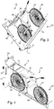
figure 1 est une vue en perspective d'un chariot pour transporter une bicyclette, ce chariot étant conforme à l'invention ; - la
figure 2 est une vue semblable à lafigure 1 mais avec une bicyclette maintenue dans ce chariot ; - la
figure 3 est une vue semblable à lafigure 2 mais avec le chariot dans lequel est maintenu la bicyclette qui est en cours de basculement entre la position nominale montrée sur lafigure 2 et une position de chargement/déchargement ; - la
figure 4 est une vue semblable auxfigures 2 et3 mais avec le chariot qui est dans la position de chargement/déchargement ; - la
figure 5 est une vue semblable à lafigure 4 mais avec le bloqueur qui est en position dégagée où son plastron est à l'écart de la bicyclette ; - la
figure 6 est une vue semblable à lafigure 5 mais avec la bicyclette qui a été enlevée du chariot ; - la
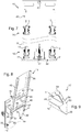
figure 7 est une vue en élévation montrant le dessous du chariot en position de chargement/déchargement (figures 4 à 6 ), et montrant également le sol ; - la
figure 8 est un agrandissement de la partie supérieure desfigures 5 et 6 sur laquelle on voit bien le bloqueur, en position dégagée ; - la
figure 9 est un agrandissement de la partie droite de lafigure 6 , sur laquelle on voit bien le crochet fixé à l'extrémité distale du mât ; - la
figure 10 est une vue semblable à lafigure 2 mais avec une bicyclette différente maintenue dans le chariot ; et - la
figure 11 montre le chariot de lafigure 2 et le chariot de lafigure 10 attelés l'un à l'autre.
- the
figure 1 is a perspective view of a carriage for transporting a bicycle, this carriage being in accordance with the invention; - the
figure 2 is a view similar to thefigure 1 but with a bicycle kept in this cart; - the
figure 3 is a view similar to thefigure 2 but with the trolley in which is held the bicycle which is being tilted between the nominal position shown on thefigure 2 and a loading / unloading position; - the
figure 4 is a view similar tofigures 2 and3 but with the cart in the loading / unloading position; - the
figure 5 is a view similar to thefigure 4 but with the blocker in an open position where his chest is away from the bicycle; - the
figure 6 is a view similar to thefigure 5 but with the bicycle that has been removed from the cart; - the
figure 7 is an elevational view showing the underside of the truck in the loading / unloading position (Figures 4 to 6 ), and also showing the ground; - the
figure 8 is an enlargement of the upper part ofFigures 5 and 6 on which we can clearly see the blocker, in an unobstructed position; - the
figure 9 is an enlargement of the right part of thefigure 6 , on which we can see the hook attached to the distal end of the mast; - the
figure 10 is a view similar to thefigure 2 but with a different bicycle kept in the carriage; and - the
figure 11 shows the trolley of thefigure 2 and the trolley of thefigure 10 hitched to each other.
Le chariot 10 illustré sur les dessins comporte un plateau 11, un premier couple 12 de roues 13, un deuxième couple 14 de roues 15, un mât 16, un crochet 17 et un bloqueur 18.The
Le plateau 11 présente une première face principale 20, qui est en regard du sol dans la position nominale du chariot (
Le plateau 11 présente des faces latérales 22 à 25 qui s'étendent chacune entre un bord de la première face principale 20 et un bord de la seconde face principale 21.The
Ici, le plateau 11 a un contour rectangulaire. Une première face latérale 22 et une deuxième face latérale 23 correspondent aux petits côtés du contour rectangulaire. Une troisième face latérale 24 et une quatrième face latérale 25 correspondent aux grands côtés du contour rectangulaire.Here, the
Les roues 13 et 15 sont fixées au plateau 11 du côté de la première face principale 20.The
Le mât 16 est fixé au plateau 11 du côté de la seconde face principale 21. Le mât 16 s'étend transversalement au plateau 11 entre une extrémité proximale 26 et une extrémité distale 27.The
Comme on le voit bien sur la
L'extrémité proximale 26 du mât 16 est ici adjacente à un bord de la seconde face principale 21, en l'occurrence le bord situé le long de la première face latérale 22.The
Le creux 28 du mât 16 est du côté opposé au bord qui longe la première face latérale 22.The hollow 28 of the
Ainsi, le creux 28 est tourné vers l'extrémité du chariot 10 qui est opposée à l'extrémité à laquelle se trouve le mât 16.Thus, the hollow 28 is turned towards the end of the
Le crochet 17 est fixé à l'extrémité distale du mât 16. Le crochet 17 s'étend du côté du creux 28 du mât 16.The
Le bloqueur 18 comporte un plastron 30, un cadre 31 portant le plastron 30 et des vérins élastiques 32 pour solliciter le cadre 31.The
Le cadre 31 est articulé vis-à-vis du plateau 11. Chacun des vérins élastiques 32 est articulé à la fois vis-à-vis du plateau 11 et vis-à-vis du cadre 31.The
Le plastron 30 est mobile suivant un trajet prédéterminé entre une position la plus proche du mât montrée sur la
Du fait que le plastron 30 est porté par le cadre 31 articulé vis-à-vis du plateau 11, ce trajet est ici en arc de cercle.Because the
Le chariot 10 est configuré pour maintenir entre le mât 16 et le bloqueur 18 une bicyclette, telle que la bicyclette 35 montrée sur les
La bicyclette ainsi maintenue est suspendue au crochet 17 par sa roue avant 37. Le plastron 30 est en appui sur la selle 39. La roue avant 37 et la roue arrière 38 sont engagées dans le creux 28 du mât 16.The bicycle thus held is suspended from the
Le chariot 10 maintient ainsi la bicyclette telle que 35 ou 36 lorsqu'il est en position nominale (
Dans l'exemple illustré, le chariot 10 est configuré pour admettre, en outre de la position nominale, une position de chargement/déchargement (
Alors que dans la position nominale (
Ainsi que montré sur les
On peut par exemple bloquer les roues 13 du couple 12 situées du même côté que le mât 16 et saisir avec une main le haut du mât 16 pour amorcer le mouvement de basculement puis accompagner ce mouvement en saisissant à un certain moment la bicyclette en place dans le chariot 10, ou le bloqueur 18, ou le plateau 11 pour contrôler le mouvement de basculement, en particulier pour retenir le chariot 10 lorsque le mât 16 se rapproche du sol.For example, it is possible to lock the
Pour libérer la bicyclette telle que 35 ou 36 lorsque le chariot 10 est dans la position de chargement/déchargement, on saisit le plastron 30 ou le cadre 31 pour éloigner le plastron 30 de la bicyclette jusqu'à ce que le plastron 30 se place dans la position dégagée, c'est-à-dire la position où il est le plus éloigné du mât 16. On est alors dans la position illustrée sur la
Ainsi qu'expliqué ultérieurement, les vérins élastiques 32 font rester le plastron 30 dans la position dégagée.As explained later, the
On peut alors saisir la bicyclette pour la placer hors du chariot 10, ainsi que montré sur la
Pour mettre en place une bicyclette dans le chariot 10, on procède de façon semblable mais en sens inverse, c'est-à-dire que l'on saisit la bicyclette pour placer ses roues dans le creux 28 du mât 16 tout en veillant à ce que le crochet 17 s'engage avec la roue avant 37, on agit sur le plastron 30 ou le cadre 31 pour rapprocher le plastron 30 du mât 16, les vérins élastiques 32 sollicitent alors le cadre 31 pour que le plastron 30 vienne en appui sur la selle 39, et on fait basculer le chariot 10 pour le ramener en position nominale.To place a bicycle in the
On observera que les différents mouvements à accomplir pour charger ou décharger une bicyclette sont chacun simple et commode à accomplir, y compris dans le cas d'une bicyclette lourde (par exemple une bicyclette à assistance électrique).It will be observed that the different movements to be performed to load or unload a bicycle are each simple and convenient to accomplish, including in the case of a heavy bicycle (eg an electric bicycle).
Au cours du basculement, du fait que la bicyclette passe d'une position horizontale à une position verticale, il descend légèrement par rapport au mât 16 jusqu'à être suspendu au crochet 17.During the tilting, as the bicycle moves from a horizontal position to a vertical position, it descends slightly with respect to the
Ainsi qu'expliqué ultérieurement, l'agencement du crochet 17 est tel que lorsque la bicyclette est suspendue au crochet 17, la roue avant 37 a tendance à pénétrer dans le creux 28 du mât 16.As explained later, the arrangement of the
L'effort exercé par le plastron 30 sur la selle 39 du fait des vérins élastiques 32 sollicite la roue arrière 38 à s'enfoncer dans le creux 28 du mât 16.The force exerted by the
D'une façon générale, lorsqu'une bicyclette telle que la bicyclette 35 ou la bicyclette 36 est maintenue dans le chariot 10, le plan médian du creux 28 du mât 16 et le plan médian de la bicyclette sont alignés.In general, when a bicycle such as
Le plastron 30 présente une largeur, c'est-à-dire une dimension orientée transversalement au plan médian du creux du mât, qui est plus grande que la largeur d'une selle de bicyclette telle que la selle 39 de la bicyclette 35 ou de la bicyclette 36, la largeur de la selle étant sa dimension orientée transversalement au plan médian de la bicyclette.The
Le cadre 31 est rigide et le plastron 30 est en matière flexible et élastique. Ici, le plastron 30 est fait dans une feuille de matière élastomère.The
Du fait que le plastron 30 est plus large que la selle telle que 39 et qu'il est en matière flexible et élastique, et du fait que le plastron 30 est maintenu en appui sur la selle par les vérins élastiques 32, le plastron 30 enveloppe étroitement la selle de sorte que la selle ne peut glisser vis-à-vis du plastron 30 que si des efforts très élevés sont exercés.Because the
Du fait que le cadre 31 qui porte le plastron 30 est rigide et du fait que le seul mouvement que peut effectuer le cadre 31 est un mouvement de pivotement vis-à-vis du plateau 11 autour d'une direction orientée transversalement au plan médian du creux du mât, le plastron 30 empêche ou en tout cas limite fortement les mouvements de la selle suivant une direction transversale au plan médian de la bicyclette.Because the
Etant donné par ailleurs que les roues de la bicyclette sont enfoncées dans le creux 28 du mât 16, et que ces roues sont donc bien maintenues par le mât 16, la bicyclette telle que 35 ou 36 ne peut pas osciller autour du crochet 17, ou en tout cas ne peut osciller que très modérément.Since, moreover, the wheels of the bicycle are sunk into the
Par conséquent, le transport de la bicyclette peut s'opérer dans d'excellentes conditions.Therefore, the transport of the bicycle can take place under excellent conditions.
Dans l'exemple illustré, le mât 16 a une longueur de 1,90 m. D'une façon générale, pour que le chariot puisse convenir aux bicyclettes courantes, il est avantageux que le mât ait une longueur comprise entre 1,75 m et 1,95 m.In the illustrated example, the
Dans l'exemple illustré, le plastron a une largeur de 35 cm. D'une façon générale, il est avantageux que le plastron ait une largeur comprise entre 25 cm et 40 cm.In the example illustrated, the front plate has a width of 35 cm. In general, it is advantageous that the plastron has a width of between 25 cm and 40 cm.
D'une façon générale, vu les dimensions que l'on rencontre en pratique pour les bicyclettes courantes, il est avantageux que le plastron soit en mesure de venir en appui sur une selle de bicyclette qui se trouve à une distance comprise entre 50 cm et 80 cm du mât ; et à une distance du plateau comprise entre 50 cm et 1,20 m.In general, given the dimensions that are encountered in practice for common bicycles, it is advantageous for the plastron to be able to bear against a saddle of a bicycle which is at a distance of between 50 cm and 80 cm from the mast; and at a distance from the plateau between 50 cm and 1.20 m.
On observera que le chariot 10 est en mesure de maintenir une bicyclette sans aucun élément latéral à la bicyclette, c'est-à-dire situé à gauche ou à droite de celle-ci, si ce n'est le mât 16 au voisinage des pneus et le bloqueur 18 au voisinage de la selle.It will be observed that the
Ainsi, le chariot 10, y compris lorsqu'il est chargé par une bicyclette, peut être particulièrement étroit, en ayant par exemple une largeur de 40 cm.Thus, the
Par ailleurs, du fait de l'absence dans le chariot 10 d'élément latéral à la bicyclette (si ce n'est au niveau des pneus et de la selle), il est possible d'observer la bicyclette alors qu'elle est maintenue par le chariot 10. Cela est utile par exemple lorsque la bicyclette telle que 35 ou 36 est amenée à un atelier de réparation où doit être effectué un diagnostic. En effet, le diagnostic pourra être effectué le plus souvent sans décharger la bicyclette, et le chariot chargé avec la bicyclette pourra ensuite être conduit à une zone d'attente.Moreover, because of the absence in the
Ainsi que montré sur la
Ainsi que montré sur la
On notera que, pour simplifier les dessins, les tétons 41 sont illustrés uniquement sur la
On va maintenant décrire plus en détail le bloqueur 18 à l'appui de la
Le cadre 31 est ici formé par deux longerons 45 et par deux traverses 46.The
Le plastron 30 s'étend entre les deux longerons 45 dans une zone située entre une extrémité des longerons 45 et les traverses 46.The
De chaque côté du cadre 31, le longeron 45 et le vérin élastique 32 sont agencés de façon semblable. Dans ce qui suit, on décrit l'agencement et le fonctionnement d'un côté mais il est entendu que cette description vaut également pour l'autre côté.On each side of the
Le longeron 45 est articulé vis-à-vis du plateau 11 grâce à une articulation 47 portée par une console 48.The
Le vérin élastique 32 est articulé vis-à-vis du plateau 11 grâce à une articulation 49 portée par une console 50.The
Le vérin élastique 32 est articulé vis-à-vis du longeron 45 grâce à une articulation 51.The
Le vérin élastique 32 est un bras à longueur variable tendant à prendre une longueur maximale.The
Lorsque les articulations 47, 49 et 51 sont alignées, la longueur du vérin élastique 32 est minimale. Le plastron 30 est alors dans une position intermédiaire entre la position la plus proche du mât 16 (
Lorsque l'articulation 51 est, par rapport à une ligne imaginaire joignant les articulations 47 et 49, du côté du plateau 11, le vérin élastique 32 tend à faire tourner le cadre 31 dans le sens où le plastron 30 se rapproche du mât 16.When the
Lorsque l'articulation 51 est, par rapport à une ligne imaginaire joignant les articulations 47 et 49, du côté qui est opposé au plateau 11, le vérin élastique 32 tend à faire tourner le cadre 31 dans le sens où le plastron 30 s'éloigne du mât 16.When the
Ainsi, le bloqueur 18 est configuré pour que le vérin élastique 32 sollicite le plastron 30 à se rapprocher du mât 16 entre la position la plus proche du mât 16 et la position intermédiaire ; et pour que le vérin élastique 32 sollicite le plastron 30 à s'éloigner du mât 16 entre la position intermédiaire et la position la plus éloignée du mât 16 (position dégagée).Thus, the
Le mât 16 comporte une paroi de fond 51 (
L'ouverture du creux 28 du mât 16 se trouve entre les ailes latérales 52.The opening of the hollow 28 of the
Ainsi, le creux 28 du mât 16 présente d'abord une partie à largeur constante, située entre les ailes latérales 52 puis une partie à largeur diminuant progressivement, délimitée par la paroi de fond 51.Thus, the hollow 28 of the
Ici, les ailes latérales 52 ont une largeur qui est plus grande au niveau de l'extrémité proximale 26 qu'au niveau de l'extrémité distale 27 du mât 16.Here, the
D'une façon générale, le mât 16 est centré latéralement vis-à-vis du plateau 11, c'est-à-dire que le mât 16 est à égale distance du bord correspondant à la face latérale 24 et du bord correspondant à la face latérale 25.In general, the
Le plan médian du creux 28 est orienté parallèlement aux grands côtés du contour rectangulaire du plateau 11.The median plane of the hollow 28 is oriented parallel to the long sides of the rectangular contour of the
Le plateau 11 et le mât 16 sont ici en matière métallique, en l'occurrence en acier. Ils sont soudés l'un à l'autre.The
Le plateau 11 est plus précisément une plaque métallique massive, grâce à quoi le plateau 11 peut jouer le rôle de lest abaissant le centre de gravité du chariot 10, au bénéfice de sa stabilité.The
Le crochet 17 comporte une âme centrale rigide 53 fixée à l'extrémité distale 27 du mât 16. Ici, l'âme 53 est en acier et est fixée au mât 16 par soudure.The
En outre de l'âme 53, le crochet 17 comporte deux garnitures 54 en matière rigide mais moins dure que celle de l'âme 53. Ici, les garnitures 54 sont en matière plastique.In addition to the
L'âme 53, qui est ici formée d'une seule pièce, comporte une base 55 et une patte courbée 56.The
La base 55 a un contour correspondant à celui de la tranche du mât 16 à son extrémité distale 27, étant ici précisé que cette tranche est inclinée par rapport à la direction générale du mât 16.The
La base 55 est soudée au mât 16 tout au long de sa tranche.The
La patte courbée 56 prend racine latéralement à la base 55.The
A partir de sa racine, la patte courbée 56 comporte une portion s'étendant suivant la direction du mât 16 puis une portion s'étendant transversalement à la direction du mât 16.From its root, the
Les garnitures 54 prennent en sandwich la patte courbée 56. Elles ont la même forme que cette dernière mais légèrement plus larges, de sorte que les garnitures 54 sont en débord de la patte courbée 56 du côté concave de celle-ci.The
Le contact entre la roue avant de la bicyclette telle que 35 ou 36 et le crochet 17 est prévu pour être fait par les portions en débord des garnitures 54.The contact between the front wheel of the bicycle such as 35 or 36 and the
L'agencement du crochet 17 permet tout à la fois d'éviter de blesser la roue de la bicyclette puisque le contact s'effectue par une matière qui n'est pas extrêmement dure et de bénéficier de la solidité procurée par l'âme 53.The arrangement of the
Le crochet 17 est agencé pour que la zone de contact avec la roue de la bicyclette soit suffisamment éloignée du mât 16 pour permettre un engagement aisé du crochet avec la roue et suffisamment proche pour qu'il existe un bras de levier entre le point de contact et le moyeu de la roue de sorte qu'il existe un couple tendant à faire pénétrer la roue dans le creux 28 du mât 16 lorsque la bicyclette est suspendue au crochet 17.The
On observera que la partie du crochet 17 s'engageant avec la roue de la bicyclette, c'est-à-dire la patte courbée 56, recouverte des garnitures 54, a une épaisseur particulièrement faible ; et qu'au surplus, du fait de son inclinaison, a une orientation semblable à celle des rayons de la roue.It will be observed that the part of the
On notera que, de manière générale, le rayonnage des roues de bicyclette est ainsi fait que tous les quatre rayons, on dispose d'un interstice assez large entre deux rayons sensiblement parallèles. Il est commode d'insérer le crochet 17 dans un tel interstice.It will be noted that, in general, the racking of the bicycle wheels is thus made that all four spokes, there is a fairly wide gap between two substantially parallel radii. It is convenient to insert the
Le crochet 17 peut ainsi coopérer dans les meilleures conditions avec la roue de la bicyclette.The
On observera que le crochet 17 est à orientation fixe vis-à-vis du mât 16. Cela offre l'avantage, par rapport à un crochet articulé, d'éviter que le crochet se rabatte contre le mât lorsque le chariot 10 est en position de chargement/déchargement, ce qui nécessiterait qu'il soit relevé par l'utilisateur pour être engagé dans la roue de la bicyclette.It will be observed that the
Ainsi qu'indiqué ci-dessus et comme montré sur la
Ce système d'attelage comporte, d'un côté du chariot 10, le timon 40. Du côté opposé au côté où se trouve le timon 40, le chariot 10 comporte un crochet 60.This coupling system comprises, on one side of the
Le timon 40 présente une fente centrale 61 configurée pour recevoir un doigt du crochet 60.The
Ainsi, lorsqu'un crochet tel que le crochet 60 est engagé dans la fente 61 du timon 40, le timon et le crochet peuvent coulisser l'un par rapport à l'autre.Thus, when a hook such as the
L'attelage ainsi formé admet une position rétractée dans laquelle les deux chariots attelés l'un à l'autre sont rapprochés et une position déployée dans laquelle les deux chariots attelés l'un à l'autre sont éloignés.The hitch thus formed admits a retracted position in which the two carriages coupled to each other are close together and an extended position in which the two carriages coupled to one another are distant.
Pour plus de détail sur le système d'attelage que comporte le chariot 10, on pourra se reporter à la demande de brevet français
Pour permettre au chariot 10 d'être aisément remorqué en tirant sur le timon 40, les roues 13 du premier couple 12 (situé du même côté que le timon 40) sont librement orientables et les roues 15 du deuxième couple 14 (situé du même côté que le crochet 60) sont à orientation fixe suivant la direction de déplacement prévue pour le chariot 10, c'est-à-dire ici l'orientation des grands côtés du contour rectangulaire du plateau 11.To allow the
Dans une variante non illustrée, plutôt que de servir à transporter une bicyclette, le chariot sert à ranger une bicyclette à un emplacement prédéterminé.In a variant not shown, rather than being used to transport a bicycle, the carriage serves to store a bicycle at a predetermined location.
Dans cette variante, plutôt que des roues telles que les roues 13 et 15, le chariot comporte des organes de guidage à basculement du plateau tel que 11 par rapport au sol, configurés pour que le chariot admette une position nominale où le plateau tel que 11 est couché et une position de chargement/déchargement où le plateau tel que 11 est debout.In this variant, rather than wheels such as the
Bien entendu, c'est dans la position nominale que la bicyclette est rangée.Of course, it is in the nominal position that the bicycle is stored.
Les organes de guidage à basculement par rapport au sol sont par exemple configurés pour que le plateau, et plus généralement le chariot, pivote autour d'une direction orientée comme la face latérale 22 et située à proximité de cette face latérale, de sorte que le chariot selon cette variante bascule entre la position nominale et la position de chargement/déchargement comme le chariot 10 de la façon montrée sur les
Les organes de montage à basculement sont par exemple mis en oeuvre grâce à des charnières entre le plateau tel que 11 et un plancher posé sur le sol.The tilt mounting members are for example implemented by hinges between the plate such as 11 and a floor on the floor.
Ce plancher est par exemple associé à des joues entre lesquelles vient le chariot en position nominale. Pour fermer l'espace de rangement de la bicyclette, un panneau peut être prévu entre les joues à l'arrière (côté où se trouve le bloqueur 18 en position nominale) et sur le dessus tandis qu'à l'avant (côté où se trouve le mât 16) un panneau est associé au chariot.This floor is for example associated with cheeks between which the carriage in nominal position. To close the storage space of the bicycle, a panel can be provided between the cheeks at the rear (side where the
Dans cette variante, le plateau tel que 11 peut être agencé différemment d'une plaque ayant deux faces principales, par exemple agencé en forme de poutre en U dont le segment central est du côté du mât tel que 16.In this variant, the
Dans des variantes non illustrées :
- le nombre de vérins élastiques tels que 32 est différent de deux, par exemple un seul ou quatre ;
- les vérins élastiques sont remplacés par un autre type de bras élastique à longueur variable, par exemple un ressort entourant une tige de guidage ;
- la section du mât est différente, par exemple en U ;
- le mât est éloigné des bords du plateau ;
- les vérins élastiques tels que 32 sont remplacés par d'autres organes pour résister à ce que le plastron s'éloigne du mât en position chargée avec une bicyclette, par exemple des organes à cliquet pour permettre au plastron de venir en appui sur la selle d'une bicyclette et pour lui interdire de s'en éloigner ; et de même pour faire rester le plastron en position dégagée, par exemple en prévoyant deux systèmes à cliquet (un pour chaque sens de déplacement) entre lesquels on permute ;
- le plateau est différent d'une plaque métallique massive, par exemple une structure ajourée en métal perforé ou en treillis de fils métalliques associée le cas échéant à un lest économique, par exemple un bloc de ciment ;
- le plastron est agencé différemment, par exemple en étant moins large ; et/ou
- le chariot comporte plusieurs mâts et autant de bloqueurs sur un même chariot, afin d'accueillir plusieurs bicyclettes.
- the number of elastic cylinders such as 32 is different from two, for example one or four;
- the elastic cylinders are replaced by another type of elastic arm variable length, for example a spring surrounding a guide rod;
- the section of the mast is different, for example in U;
- the mast is away from the edges of the board;
- the resilient cylinders such as 32 are replaced by other members to resist that the plastron away from the mast in the loaded position with a bicycle, for example ratchet members to allow the plastron to bear against the saddle a bicycle and to prevent it from moving away from it; and likewise to keep the plastron in the disengaged position, for example by providing two ratchet systems (one for each direction of movement) between which is permuted;
- the plate is different from a solid metal plate, for example a pierced perforated metal structure or wire mesh associated optionally with an economic ballast, for example a block of cement;
- the plastron is arranged differently, for example by being less wide; and or
- the carriage has several masts and as many blockers on the same carriage, to accommodate several bicycles.
De nombreuses autres variantes sont possibles en fonction des circonstances, et l'on rappelle à cet égard que l'invention ne se limite pas aux exemples décrits et représentés.Many other variants are possible depending on the circumstances, and it is recalled in this regard that the invention is not limited to the examples described and shown.
Claims (15)
- Cart for transporting a bicycle (35, 36), comprising:- a tray (11) having a first main face (20), a second main face (21) and side faces (22-25) each extending between an edge of the first main face (20) and an edge of the second main face (21);- wheels (13, 15), attached to the tray (11) on the first main face (20) side;- a pole (16) attached to the tray (11) on the second main face (21) side, extending transversely to the tray (11) between a proximal end (26) and a distal end (27); and- a hook (17) attached to the distal end (27) of the pole (16),characterised in that the pole (16) delimits a cavity (28) in the form of a trough, the hook (17) extends on the cavity (28) side of the pole (16), and said cart (10):- comprises a securing means (18) comprising a panel (30) which is movable along a predetermined path in which the panel moves towards or away from the pole (16), and comprising an element (32) for resisting movement of the panel (30) away from the pole (16); and- is designed to hold a bicycle (35, 36) between the pole (16) and the securing means (18), with the bicycle (35, 36) suspended from the hook (17) by its front wheel (37), the rear wheel (38) and the front wheel (37) of the bicycle (35, 36) being engaged in the cavity (28) of the pole (16) and the panel (30) resting on the saddle (39) of the bicycle (35, 36).
- Cart according to claim 1, characterised in that the proximal end (26) of the pole (16) is adjacent to an edge of the second main face (21) of the tray (11), the cavity (28) of the pole (16) is located on the side away from said edge, the cart (10) is designed to allow a nominal position in which the pole (16) is upright while the tray (11) lies flat with the wheels (13, 15) in contact with the ground, and to allow a loading/unloading position in which the tray (11) is upright while the pole (16) lies flat along the ground with the cavity (28) directed upwards, the transition between the nominal position and the loading/unloading position being carried out by tipping the cart (10).
- Cart according to either claim 1 or claim 2, characterised in that it comprises, in order to be coupled to a similar cart, a drawbar (40) on one side and a hook (60) on a second side away from the first side.
- Cart for storing a bicycle (35, 36), comprising:- a tray (11);- guiding elements for tipping the tray (11) with respect to the ground, designed such that the cart allows a nominal position in which the tray is lying flat and a loading/unloading position in which the tray is upright;- a pole (16) attached to the tray (11), extending transversely to the tray (11) between a proximal end (26) and a distal end (27); and- a hook (17) attached to the distal end (27) of the pole (16),characterised in that the pole (16) delimits a cavity (28) in the form of a trough, the hook (17) extends on the cavity (28) side of the pole (16), and said cart (10):- comprises a securing means (18) comprising a panel (30) which is movable along a predetermined path in which the panel moves towards or away from the pole (16), and comprising an element (32) for resisting movement of the panel (30) away from the pole (16); and- is designed to hold a bicycle (35, 36) between the pole (16) and the securing means (18), with in the nominal position the bicycle (35, 36) suspended from the hook (17) by its front wheel (37), the rear wheel (38) and the front wheel (37) of the bicycle (35, 36) engaged in the cavity (28) of the pole (16) and the panel (30) resting on the saddle (39) of the bicycle (35, 36).
- Cart according to any of claims 1 to 4, characterised in that the panel (30) has a width greater than the width of a saddle (39) of a bicycle (35, 36).
- Cart according to any of claims 1 to 5, characterised in that the panel (30) is made of a flexible and resilient material.
- Cart according to any of claims 1 to 6, characterised in that the securing means (18) is designed such that the panel (30) allows a disengaged position in which it is spaced apart from the pole (16) and comprises an element (32) for making the panel (30) stay in the disengaged position.
- Cart according to any of claims 1 to 7, characterised in that the element for resisting movement of the panel (30) away from the pole (16) is a resilient element (32) which biases the panel (30) to move towards the pole (16).
- Cart according to claim 8, characterised in that the securing means (18) is designed such that the resilient element (32) biases the panel (30) to move towards the pole (16) between a position closest to the pole (16) and an intermediate position, and such that the resilient element biases the panel (30) to move away from the pole (16) between the intermediate position and a position furthest away from the pole (16).
- Cart according to claim 9, characterised in that the resilient element is a variable-length arm (32) that is prone to take a maximum length, the securing means (18) comprises a frame (31) bearing the panel (30), a hinge between the frame (31) and the tray (11), a hinge between one end of the variable-length arm (32) and the tray (11), and a hinge between the other end of the variable-length arm (32) and the frame (31), and said three hinges are aligned in the intermediate position of the panel (30).
- Cart according to any of claims 1 to 10, characterised in that the securing means (18) comprises a frame (31) bearing the panel (30) and said frame (31) comprises two side-members (45), each hinged to the tray (11).
- Cart according to any of claims 1 to 11, characterised in that said pole (16) comprises a base wall (51) having a V-shaped cross section and side walls (52) having a straight cross section, each side wing (52) running along one of the ends of the base wall (51).
- Cart according to any of claims 1 to 12, characterised in that said hook (17) comprises a central web (53) and fittings (54) sandwiching a curved tab (56) which the central web (53) comprises, the fittings (54) projecting from the curved tab (56) on the concave side thereof.
- Cart according to any of claims 1 to 13, characterised in that said hook (17) is inclined relative to the pole (16) and has a fixed orientation.
- Cart according to any of claims 1 to 14, characterised in that said tray (11) is formed by a solid metal plate.
Applications Claiming Priority (2)
| Application Number | Priority Date | Filing Date | Title |
|---|---|---|---|
| FR1550447A FR3031716B1 (en) | 2015-01-20 | 2015-01-20 | TROLLEY FOR TRANSPORTING A BICYCLE |
| PCT/FR2016/050108 WO2016116701A1 (en) | 2015-01-20 | 2016-01-20 | Cart for transporting or storing a bicycle |
Publications (2)
| Publication Number | Publication Date |
|---|---|
| EP3247610A1 EP3247610A1 (en) | 2017-11-29 |
| EP3247610B1 true EP3247610B1 (en) | 2019-03-13 |
Family
ID=52824436
Family Applications (1)
| Application Number | Title | Priority Date | Filing Date |
|---|---|---|---|
| EP16705567.2A Active EP3247610B1 (en) | 2015-01-20 | 2016-01-20 | Cart for transporting or storing a bicycle |
Country Status (6)
| Country | Link |
|---|---|
| EP (1) | EP3247610B1 (en) |
| CN (1) | CN107107935B (en) |
| DK (1) | DK3247610T3 (en) |
| ES (1) | ES2724009T3 (en) |
| FR (1) | FR3031716B1 (en) |
| WO (1) | WO2016116701A1 (en) |
Families Citing this family (6)
| Publication number | Priority date | Publication date | Assignee | Title |
|---|---|---|---|---|
| FR3031716B1 (en) * | 2015-01-20 | 2017-02-17 | Labadis | TROLLEY FOR TRANSPORTING A BICYCLE |
| DE202016005478U1 (en) * | 2016-08-29 | 2016-10-27 | Messingschlager GmbH & Co. KG | Bicycle stand |
| CN107738607A (en) * | 2017-10-31 | 2018-02-27 | 天津市驰恩特车业有限公司 | A kind of bicycle transports fixing device |
| CN108569321B (en) * | 2018-05-22 | 2020-08-11 | 台州市路桥高精模具厂 | Simple dragging vehicle for shared bicycle |
| CN108945175B (en) * | 2018-06-20 | 2024-01-12 | 湖北三峡职业技术学院 | Wall bicycle frame and using method thereof |
| PL3623546T3 (en) * | 2018-09-11 | 2021-05-31 | Smart City Concepts Gmbh | Conveyor for bicycles |
Family Cites Families (8)
| Publication number | Priority date | Publication date | Assignee | Title |
|---|---|---|---|---|
| FR2800676B1 (en) | 1999-11-09 | 2002-01-18 | Valeo Thermique Moteur Sa | HITCHING DEVICE FOR HANDLING TROLLEY |
| US8528749B2 (en) * | 2011-01-07 | 2013-09-10 | David Kerman | Free-standing storage rack for one or more bicycles |
| AU2013220934B2 (en) * | 2012-02-17 | 2016-09-08 | Adrian Min Yan LEE | Remote storage system |
| ES1077123Y (en) * | 2012-05-04 | 2012-09-07 | Serveis Maquinaria Banyolina S L | Wall mount for bicycles |
| AT513790B1 (en) * | 2012-12-27 | 2015-11-15 | Gerhard Bauer S E Bike Gmbh | Vertical bike holder |
| ES1078839Y (en) * | 2013-01-29 | 2013-06-12 | Ferrer Francisco E Franch | Mobile bike stand |
| FR3031716B1 (en) * | 2015-01-20 | 2017-02-17 | Labadis | TROLLEY FOR TRANSPORTING A BICYCLE |
| CN205615389U (en) * | 2016-03-29 | 2016-10-05 | 深圳市凯卓立液压设备有限公司 | Double -deck bicycle transport box structure |
-
2015
- 2015-01-20 FR FR1550447A patent/FR3031716B1/en not_active Expired - Fee Related
-
2016
- 2016-01-20 CN CN201680006156.8A patent/CN107107935B/en active Active
- 2016-01-20 EP EP16705567.2A patent/EP3247610B1/en active Active
- 2016-01-20 DK DK16705567.2T patent/DK3247610T3/en active
- 2016-01-20 WO PCT/FR2016/050108 patent/WO2016116701A1/en active Application Filing
- 2016-01-20 ES ES16705567T patent/ES2724009T3/en active Active
Non-Patent Citations (1)
| Title |
|---|
| None * |
Also Published As
| Publication number | Publication date |
|---|---|
| WO2016116701A1 (en) | 2016-07-28 |
| CN107107935A (en) | 2017-08-29 |
| ES2724009T3 (en) | 2019-09-05 |
| FR3031716A1 (en) | 2016-07-22 |
| DK3247610T3 (en) | 2019-06-17 |
| CN107107935B (en) | 2019-09-27 |
| EP3247610A1 (en) | 2017-11-29 |
| FR3031716B1 (en) | 2017-02-17 |
Similar Documents
| Publication | Publication Date | Title |
|---|---|---|
| EP3247610B1 (en) | Cart for transporting or storing a bicycle | |
| EP0029384B1 (en) | Lift truck with synchronised adjustement of variable rolling and gripping surfaces | |
| FR2774639A1 (en) | Lorry mounted skip handling frame | |
| FR2704189A1 (en) | Apparatus for allowing a vehicle to pick up or place a load such as a bucket on the ground, and possibly to empty it | |
| EP1666365A1 (en) | Palletcontainer with two support surfaces | |
| EP0905083B1 (en) | Lift truck with mast adapted to be mounted on the back of a transport vehicle | |
| EP3377397B1 (en) | Vehicle for transporting a load | |
| EP0374019A1 (en) | System for transporting and placing at least one bridge element using a vehicle such as a bridge laying vehicle | |
| EP3791846B1 (en) | Securing device for motorised loading and/or extraction of a carriage supporting a stretcher, associated receiver and ambulance | |
| FR2822422A1 (en) | APPARATUS FOR HANDLING A LOAD, VEHICLE CONTAINING IT AND PROCESS FOR LIFTING A LOAD WITH SUCH A VEHICLE | |
| EP3177467B1 (en) | Set of trolleys configured to be towed | |
| EP1243464A1 (en) | Load handling apparatus and vehicle including such apparatus | |
| EP3400622B1 (en) | Stationary shelter for storing at least one electrical energy storage unit | |
| FR2516022A1 (en) | TROLLEY TROLLEY | |
| FR2750088A1 (en) | Vehicle equipped with hydraulic lifting arm | |
| FR2908092A1 (en) | Heavy object e.g. motor cycle, loading and unloading device for e.g. trailer, has guiding unit guiding ramp between two positions and bringing back ramp above floor, when ramp reaches loading/unloading position | |
| CH484827A (en) | Auxiliary trolley allowing the use of a front fork lift as a side fork lift | |
| EP2990263B1 (en) | Road transport vehicle having a load-bearing structure with automatic coupling and uncoupling | |
| FR2989574A1 (en) | Device for assisting loading and unloading of stretcher in and out of e.g. military vehicle for transporting injured persons in stretcher, has arms articulated to move support between loading/unloading position and transfer position | |
| FR3037308A1 (en) | TRAILER FOR REACHING A TRACTOR VEHICLE AND ASSEMBLY COMPRISING SUCH A TRAILER | |
| WO2024008379A1 (en) | Transport trolley with suspended castors and provided with an immobilising pad | |
| FR3011177A1 (en) | BRANCARD OR BRANCH HOLDER COMPRISING FOLDING ARMRESTS | |
| FR2762299A1 (en) | Storage and transport rack for gas bottles | |
| FR3125808A1 (en) | Device for moving-tilting a stack of objects | |
| FR3100174A1 (en) | removable bucket movement system |
Legal Events
| Date | Code | Title | Description |
|---|---|---|---|
| STAA | Information on the status of an ep patent application or granted ep patent |
Free format text: STATUS: THE INTERNATIONAL PUBLICATION HAS BEEN MADE |
|
| PUAI | Public reference made under article 153(3) epc to a published international application that has entered the european phase |
Free format text: ORIGINAL CODE: 0009012 |
|
| STAA | Information on the status of an ep patent application or granted ep patent |
Free format text: STATUS: REQUEST FOR EXAMINATION WAS MADE |
|
| 17P | Request for examination filed |
Effective date: 20170721 |
|
| AK | Designated contracting states |
Kind code of ref document: A1 Designated state(s): AL AT BE BG CH CY CZ DE DK EE ES FI FR GB GR HR HU IE IS IT LI LT LU LV MC MK MT NL NO PL PT RO RS SE SI SK SM TR |
|
| AX | Request for extension of the european patent |
Extension state: BA ME |
|
| DAV | Request for validation of the european patent (deleted) | ||
| DAX | Request for extension of the european patent (deleted) | ||
| GRAP | Despatch of communication of intention to grant a patent |
Free format text: ORIGINAL CODE: EPIDOSNIGR1 |
|
| STAA | Information on the status of an ep patent application or granted ep patent |
Free format text: STATUS: GRANT OF PATENT IS INTENDED |
|
| INTG | Intention to grant announced |
Effective date: 20180703 |
|
| GRAS | Grant fee paid |
Free format text: ORIGINAL CODE: EPIDOSNIGR3 |
|
| GRAJ | Information related to disapproval of communication of intention to grant by the applicant or resumption of examination proceedings by the epo deleted |
Free format text: ORIGINAL CODE: EPIDOSDIGR1 |
|
| GRAL | Information related to payment of fee for publishing/printing deleted |
Free format text: ORIGINAL CODE: EPIDOSDIGR3 |
|
| STAA | Information on the status of an ep patent application or granted ep patent |
Free format text: STATUS: REQUEST FOR EXAMINATION WAS MADE |
|
| RAP1 | Party data changed (applicant data changed or rights of an application transferred) |
Owner name: LABADIS WORKS |
|
| GRAP | Despatch of communication of intention to grant a patent |
Free format text: ORIGINAL CODE: EPIDOSNIGR1 |
|
| STAA | Information on the status of an ep patent application or granted ep patent |
Free format text: STATUS: GRANT OF PATENT IS INTENDED |
|
| RAP1 | Party data changed (applicant data changed or rights of an application transferred) |
Owner name: LABADIS SAS |
|
| INTC | Intention to grant announced (deleted) | ||
| INTG | Intention to grant announced |
Effective date: 20181126 |
|
| GRAA | (expected) grant |
Free format text: ORIGINAL CODE: 0009210 |
|
| STAA | Information on the status of an ep patent application or granted ep patent |
Free format text: STATUS: THE PATENT HAS BEEN GRANTED |
|
| AK | Designated contracting states |
Kind code of ref document: B1 Designated state(s): AL AT BE BG CH CY CZ DE DK EE ES FI FR GB GR HR HU IE IS IT LI LT LU LV MC MK MT NL NO PL PT RO RS SE SI SK SM TR |
|
| REG | Reference to a national code |
Ref country code: GB Ref legal event code: FG4D Free format text: NOT ENGLISH |
|
| REG | Reference to a national code |
Ref country code: CH Ref legal event code: EP Ref country code: AT Ref legal event code: REF Ref document number: 1107315 Country of ref document: AT Kind code of ref document: T Effective date: 20190315 |
|
| REG | Reference to a national code |
Ref country code: DE Ref legal event code: R096 Ref document number: 602016011031 Country of ref document: DE |
|
| REG | Reference to a national code |
Ref country code: IE Ref legal event code: FG4D Free format text: LANGUAGE OF EP DOCUMENT: FRENCH |
|
| REG | Reference to a national code |
Ref country code: DK Ref legal event code: T3 Effective date: 20190613 |
|
| REG | Reference to a national code |
Ref country code: NL Ref legal event code: FP |
|
| REG | Reference to a national code |
Ref country code: LT Ref legal event code: MG4D |
|
| PG25 | Lapsed in a contracting state [announced via postgrant information from national office to epo] |
Ref country code: LT Free format text: LAPSE BECAUSE OF FAILURE TO SUBMIT A TRANSLATION OF THE DESCRIPTION OR TO PAY THE FEE WITHIN THE PRESCRIBED TIME-LIMIT Effective date: 20190313 Ref country code: SE Free format text: LAPSE BECAUSE OF FAILURE TO SUBMIT A TRANSLATION OF THE DESCRIPTION OR TO PAY THE FEE WITHIN THE PRESCRIBED TIME-LIMIT Effective date: 20190313 Ref country code: NO Free format text: LAPSE BECAUSE OF FAILURE TO SUBMIT A TRANSLATION OF THE DESCRIPTION OR TO PAY THE FEE WITHIN THE PRESCRIBED TIME-LIMIT Effective date: 20190613 Ref country code: FI Free format text: LAPSE BECAUSE OF FAILURE TO SUBMIT A TRANSLATION OF THE DESCRIPTION OR TO PAY THE FEE WITHIN THE PRESCRIBED TIME-LIMIT Effective date: 20190313 |
|
| PG25 | Lapsed in a contracting state [announced via postgrant information from national office to epo] |
Ref country code: HR Free format text: LAPSE BECAUSE OF FAILURE TO SUBMIT A TRANSLATION OF THE DESCRIPTION OR TO PAY THE FEE WITHIN THE PRESCRIBED TIME-LIMIT Effective date: 20190313 Ref country code: GR Free format text: LAPSE BECAUSE OF FAILURE TO SUBMIT A TRANSLATION OF THE DESCRIPTION OR TO PAY THE FEE WITHIN THE PRESCRIBED TIME-LIMIT Effective date: 20190614 Ref country code: LV Free format text: LAPSE BECAUSE OF FAILURE TO SUBMIT A TRANSLATION OF THE DESCRIPTION OR TO PAY THE FEE WITHIN THE PRESCRIBED TIME-LIMIT Effective date: 20190313 Ref country code: BG Free format text: LAPSE BECAUSE OF FAILURE TO SUBMIT A TRANSLATION OF THE DESCRIPTION OR TO PAY THE FEE WITHIN THE PRESCRIBED TIME-LIMIT Effective date: 20190613 Ref country code: RS Free format text: LAPSE BECAUSE OF FAILURE TO SUBMIT A TRANSLATION OF THE DESCRIPTION OR TO PAY THE FEE WITHIN THE PRESCRIBED TIME-LIMIT Effective date: 20190313 |
|
| REG | Reference to a national code |
Ref country code: ES Ref legal event code: FG2A Ref document number: 2724009 Country of ref document: ES Kind code of ref document: T3 Effective date: 20190905 |
|
| REG | Reference to a national code |
Ref country code: AT Ref legal event code: MK05 Ref document number: 1107315 Country of ref document: AT Kind code of ref document: T Effective date: 20190313 |
|
| PG25 | Lapsed in a contracting state [announced via postgrant information from national office to epo] |
Ref country code: SK Free format text: LAPSE BECAUSE OF FAILURE TO SUBMIT A TRANSLATION OF THE DESCRIPTION OR TO PAY THE FEE WITHIN THE PRESCRIBED TIME-LIMIT Effective date: 20190313 Ref country code: PT Free format text: LAPSE BECAUSE OF FAILURE TO SUBMIT A TRANSLATION OF THE DESCRIPTION OR TO PAY THE FEE WITHIN THE PRESCRIBED TIME-LIMIT Effective date: 20190713 Ref country code: AL Free format text: LAPSE BECAUSE OF FAILURE TO SUBMIT A TRANSLATION OF THE DESCRIPTION OR TO PAY THE FEE WITHIN THE PRESCRIBED TIME-LIMIT Effective date: 20190313 Ref country code: CZ Free format text: LAPSE BECAUSE OF FAILURE TO SUBMIT A TRANSLATION OF THE DESCRIPTION OR TO PAY THE FEE WITHIN THE PRESCRIBED TIME-LIMIT Effective date: 20190313 Ref country code: RO Free format text: LAPSE BECAUSE OF FAILURE TO SUBMIT A TRANSLATION OF THE DESCRIPTION OR TO PAY THE FEE WITHIN THE PRESCRIBED TIME-LIMIT Effective date: 20190313 Ref country code: EE Free format text: LAPSE BECAUSE OF FAILURE TO SUBMIT A TRANSLATION OF THE DESCRIPTION OR TO PAY THE FEE WITHIN THE PRESCRIBED TIME-LIMIT Effective date: 20190313 |
|
| PG25 | Lapsed in a contracting state [announced via postgrant information from national office to epo] |
Ref country code: SM Free format text: LAPSE BECAUSE OF FAILURE TO SUBMIT A TRANSLATION OF THE DESCRIPTION OR TO PAY THE FEE WITHIN THE PRESCRIBED TIME-LIMIT Effective date: 20190313 Ref country code: PL Free format text: LAPSE BECAUSE OF FAILURE TO SUBMIT A TRANSLATION OF THE DESCRIPTION OR TO PAY THE FEE WITHIN THE PRESCRIBED TIME-LIMIT Effective date: 20190313 |
|
| REG | Reference to a national code |
Ref country code: DE Ref legal event code: R097 Ref document number: 602016011031 Country of ref document: DE |
|
| PG25 | Lapsed in a contracting state [announced via postgrant information from national office to epo] |
Ref country code: IS Free format text: LAPSE BECAUSE OF FAILURE TO SUBMIT A TRANSLATION OF THE DESCRIPTION OR TO PAY THE FEE WITHIN THE PRESCRIBED TIME-LIMIT Effective date: 20190713 Ref country code: AT Free format text: LAPSE BECAUSE OF FAILURE TO SUBMIT A TRANSLATION OF THE DESCRIPTION OR TO PAY THE FEE WITHIN THE PRESCRIBED TIME-LIMIT Effective date: 20190313 |
|
| PLBE | No opposition filed within time limit |
Free format text: ORIGINAL CODE: 0009261 |
|
| STAA | Information on the status of an ep patent application or granted ep patent |
Free format text: STATUS: NO OPPOSITION FILED WITHIN TIME LIMIT |
|
| 26N | No opposition filed |
Effective date: 20191216 |
|
| PG25 | Lapsed in a contracting state [announced via postgrant information from national office to epo] |
Ref country code: SI Free format text: LAPSE BECAUSE OF FAILURE TO SUBMIT A TRANSLATION OF THE DESCRIPTION OR TO PAY THE FEE WITHIN THE PRESCRIBED TIME-LIMIT Effective date: 20190313 |
|
| PG25 | Lapsed in a contracting state [announced via postgrant information from national office to epo] |
Ref country code: TR Free format text: LAPSE BECAUSE OF FAILURE TO SUBMIT A TRANSLATION OF THE DESCRIPTION OR TO PAY THE FEE WITHIN THE PRESCRIBED TIME-LIMIT Effective date: 20190313 |
|
| PG25 | Lapsed in a contracting state [announced via postgrant information from national office to epo] |
Ref country code: MC Free format text: LAPSE BECAUSE OF FAILURE TO SUBMIT A TRANSLATION OF THE DESCRIPTION OR TO PAY THE FEE WITHIN THE PRESCRIBED TIME-LIMIT Effective date: 20190313 |
|
| REG | Reference to a national code |
Ref country code: CH Ref legal event code: PL |
|
| PG25 | Lapsed in a contracting state [announced via postgrant information from national office to epo] |
Ref country code: LU Free format text: LAPSE BECAUSE OF NON-PAYMENT OF DUE FEES Effective date: 20200120 |
|
| PG25 | Lapsed in a contracting state [announced via postgrant information from national office to epo] |
Ref country code: CH Free format text: LAPSE BECAUSE OF NON-PAYMENT OF DUE FEES Effective date: 20200131 Ref country code: LI Free format text: LAPSE BECAUSE OF NON-PAYMENT OF DUE FEES Effective date: 20200131 |
|
| PG25 | Lapsed in a contracting state [announced via postgrant information from national office to epo] |
Ref country code: IE Free format text: LAPSE BECAUSE OF NON-PAYMENT OF DUE FEES Effective date: 20200120 |
|
| PG25 | Lapsed in a contracting state [announced via postgrant information from national office to epo] |
Ref country code: MT Free format text: LAPSE BECAUSE OF FAILURE TO SUBMIT A TRANSLATION OF THE DESCRIPTION OR TO PAY THE FEE WITHIN THE PRESCRIBED TIME-LIMIT Effective date: 20190313 Ref country code: CY Free format text: LAPSE BECAUSE OF FAILURE TO SUBMIT A TRANSLATION OF THE DESCRIPTION OR TO PAY THE FEE WITHIN THE PRESCRIBED TIME-LIMIT Effective date: 20190313 |
|
| PG25 | Lapsed in a contracting state [announced via postgrant information from national office to epo] |
Ref country code: MK Free format text: LAPSE BECAUSE OF FAILURE TO SUBMIT A TRANSLATION OF THE DESCRIPTION OR TO PAY THE FEE WITHIN THE PRESCRIBED TIME-LIMIT Effective date: 20190313 |
|
| P01 | Opt-out of the competence of the unified patent court (upc) registered |
Effective date: 20230512 |
|
| PGFP | Annual fee paid to national office [announced via postgrant information from national office to epo] |
Ref country code: GB Payment date: 20231206 Year of fee payment: 9 |
|
| PGFP | Annual fee paid to national office [announced via postgrant information from national office to epo] |
Ref country code: NL Payment date: 20231229 Year of fee payment: 9 Ref country code: FR Payment date: 20231221 Year of fee payment: 9 Ref country code: DK Payment date: 20231228 Year of fee payment: 9 |
|
| PGFP | Annual fee paid to national office [announced via postgrant information from national office to epo] |
Ref country code: ES Payment date: 20240207 Year of fee payment: 9 |
|
| PGFP | Annual fee paid to national office [announced via postgrant information from national office to epo] |
Ref country code: DE Payment date: 20240115 Year of fee payment: 9 |
|
| PGFP | Annual fee paid to national office [announced via postgrant information from national office to epo] |
Ref country code: IT Payment date: 20240111 Year of fee payment: 9 Ref country code: BE Payment date: 20240116 Year of fee payment: 9 |