EP3247012B1 - Boom mountable robotic arm - Google Patents
Boom mountable robotic arm Download PDFInfo
- Publication number
- EP3247012B1 EP3247012B1 EP17180094.9A EP17180094A EP3247012B1 EP 3247012 B1 EP3247012 B1 EP 3247012B1 EP 17180094 A EP17180094 A EP 17180094A EP 3247012 B1 EP3247012 B1 EP 3247012B1
- Authority
- EP
- European Patent Office
- Prior art keywords
- boom
- rotation
- robotic arm
- actuator
- insulated support
- Prior art date
- Legal status (The legal status is an assumption and is not a legal conclusion. Google has not performed a legal analysis and makes no representation as to the accuracy of the status listed.)
- Active
Links
- 239000004020 conductor Substances 0.000 claims description 58
- 230000008878 coupling Effects 0.000 claims description 40
- 238000010168 coupling process Methods 0.000 claims description 40
- 238000005859 coupling reaction Methods 0.000 claims description 40
- 238000006073 displacement reaction Methods 0.000 claims description 5
- 230000003247 decreasing effect Effects 0.000 claims description 2
- 239000012212 insulator Substances 0.000 description 53
- 230000005540 biological transmission Effects 0.000 description 18
- 230000033001 locomotion Effects 0.000 description 9
- 230000003068 static effect Effects 0.000 description 5
- 238000000034 method Methods 0.000 description 4
- 238000013459 approach Methods 0.000 description 2
- 238000013461 design Methods 0.000 description 2
- 238000003780 insertion Methods 0.000 description 2
- 230000037431 insertion Effects 0.000 description 2
- 238000012423 maintenance Methods 0.000 description 2
- 229920000642 polymer Polymers 0.000 description 2
- 238000000926 separation method Methods 0.000 description 2
- 238000009825 accumulation Methods 0.000 description 1
- 239000000835 fiber Substances 0.000 description 1
- 239000011152 fibreglass Substances 0.000 description 1
- 231100001261 hazardous Toxicity 0.000 description 1
- 230000007246 mechanism Effects 0.000 description 1
Images


Classifications
-
- H—ELECTRICITY
- H02—GENERATION; CONVERSION OR DISTRIBUTION OF ELECTRIC POWER
- H02G—INSTALLATION OF ELECTRIC CABLES OR LINES, OR OF COMBINED OPTICAL AND ELECTRIC CABLES OR LINES
- H02G1/00—Methods or apparatus specially adapted for installing, maintaining, repairing or dismantling electric cables or lines
- H02G1/02—Methods or apparatus specially adapted for installing, maintaining, repairing or dismantling electric cables or lines for overhead lines or cables
- H02G1/04—Methods or apparatus specially adapted for installing, maintaining, repairing or dismantling electric cables or lines for overhead lines or cables for mounting or stretching
-
- G—PHYSICS
- G08—SIGNALLING
- G08C—TRANSMISSION SYSTEMS FOR MEASURED VALUES, CONTROL OR SIMILAR SIGNALS
- G08C19/00—Electric signal transmission systems
- G08C19/16—Electric signal transmission systems in which transmission is by pulses
Definitions
- This application relates to a robotic arm which is mountable to the boom of a service vehicle for temporarily supporting and repositioning energized power lines to enable repair or replacement or re-location of transmission or distribution conductors while energized.
- High voltage transmission and distribution lines are typically strung between a series of spaced-apart support towers or poles.
- the conductors are connected to insulators mounted or suspended from crossarms extending at the upper end of transmission or distribution poles, or conductor support points built into transmission towers. Periodically it is necessary to replace or repair the poles or towers, crossarms and insulators to maintain the electrical circuit in good working order. It is preferable if this maintenance and repair work can be performed without de-energizing the conductors in order to avoid the necessity of purchasing power from an alternative source, or other system disruptions.
- Auxiliary crossarms for temporarily lifting and supporting energized conductors from below are also well-known.
- Such crossarms typically have sleeves which are compatible to the boom jibs of derrick and bucket trucks.
- Utility companies often find it convenient to string both transmission lines and distribution lines on the same pole or tower.
- the distribution lines are usually suspended between 1.2 to 3.7 metres (four to twelve feet) below the transmission lines.
- Fold-down-flat insulators make for compactness, for example when the auxiliary cross-arm is flush down against the boom of transport, and for insertion into tight spacing between existing conductors and crossarms.
- a further prior art design is known from US 2010/1333490 A1 .
- the boom mountable robotic arm for temporarily supporting one or more energized electrical conductors may be characterized according to one aspect of the invention as including a beam pivotally mounted on a boom mounting adaptor, wherein the boom mounting adaptor is mountable onto an upper and of a boom. At least two electrically insulated support posts are mounted to and spaced apart along the beam. At least a first rotation coupling and second rotation couplings which are collectively mounted in cooperation with the beam.
- the first rotation coupling provides pivotal mounting of the beam on the boom mounting adaptor so as to provide selectively controllable rotation of the beam about a first axis of rotation, wherein the first axis of rotation extends laterally of and between the beam and an upper end of the boom mounting adaptor for rotation of the beam relative to the boom mounting adaptor in a substantially vertical plane.
- the second rotation couplings provide selectively controllable rotation of the electrically insulated support posts about corresponding second axes of rotation.
- the second axes of rotation include axes of rotation extending substantially laterally across the beam at base ends of the support posts for rotation of each support post relative to and substantially along the beam. Positions of the support posts are thereby selectively adjustable between a retracted position substantially laid flush along the beam and a pick-up position ready to receive a conductor being supported.
- Each electrically insulated support post is adapted to temporarily support an energized electrical conductor.
- a scissor linkage is mounted to the beam and the boom mounting adaptor for selectively adjusting an angular position of the beam relative to the boom mounting adaptor.
- a selectively actuable first actuator is mounted so as to cooperate between the beam and the scissor linkage.
- the scissor linkage includes first and second linkage members. Each of the first and second linkage members has, respectively, opposite first and second ends. The first ends are pivotally connected to one another. The second ends are pivotally mounted to, respectively, the beam and the boom mounting adaptor.
- the first actuator is pivotally mounted at a first end thereof to the first ends of the linkage members. A second end of the first actuator, opposite the first end of the first actuator, is mounted to the beam.
- the beam is pivotable in an angular displacement about the first rotation coupling by substantially 160 degrees relative to the boom mounting adaptor.
- the angular displacement includes a substantially horizontal orientation and a substantially vertical orientation.
- the beam may be a substantially linear beam.
- the at least two electrically insulated support posts include one or more insulated support posts mounted on each of the opposite ends of the beam.
- the support posts on each end of the beam are mounted on corresponding second rotation couplings on the opposite ends of the beam.
- the second rotation couplings have corresponding substantially parallel the second axes of rotation allowing distal ends of the pair of support posts, distal from the beam, to rotate in a substantially vertical plane into the support posts retracted positions.
- the second axes of rotation may also include axes which extend along the beams so that the posts rotate laterally relative to the beam, and may also include axes which extend vertically or off-vertically so that the posts rotate while up-standing, or wherein the second axes of rotation are a combination of these by the use of a universal joint-like coupling or other forms of multiple degree-of-freedom couplings between the posts and the beam.
- the second rotation couplings may each include a hinge mounted to the beam.
- Each hinge may include at least one hinge plate.
- Each hinge plate may have a plurality of bores therein for securing a corresponding pair of electrically insulated support posts thereto.
- Each hinge plate may have a fastener for securing the hinge plate in an operating position in which the electrically insulated support posts extend in their pick-up positions and substantially perpendicularly away from the beam.
- Each hinge plate may be pivotally mounted to a corresponding base plate which is mounted to the beam.
- the hinge plate and its corresponding base plate may have cooperating holes at opposite ends thereof so that, with a first end of the hinge plate pinned by a pin or rod or shaft to the first end of the base plate, the opposite second end of the hinge plate maybe swung or pivoted open relative to the base plate by rotation of the plates about the pin, rod or shaft.
- the second ends of the hinge plate and base plate may be pinned together for opening or pivoting open of the hinge in the opposite direction, that is, about the pin, rod or shaft pinning the second end of the hinge plate to the second end of the base plate.
- the beam may include telescopic beam extensions and a second actuator cooperating between the beam and the beam extensions for selective lengthening of the beam, and wherein the support posts are mounted on distal ends of the beam extensions.
- the beam may include a main beam member and one extension member at at least one end of the main beam member.
- the extension member extends so as to elongate the beam.
- At least one electrically insulated support posts is mounted on a distal end of the extension member, distal from the main beam member.
- An oppositely disposed pair of the extension members may be mounted on the distal ends of the main beam member.
- the extension members extend from a collapsed position to an extended position.
- the pair of support posts on the distal ends of the extension members pivot on the support posts' corresponding second rotation couplings so as to, for example, fold along the main beam member when the extension members are in their collapsed position, that is, when the beam is shortened.
- the individual or pairs of support posts on the distal ends of the extension members may pivot towards one another when pivoted about the second rotation couplings into their retracted positions.
- At least a third support post may be mounted on the main beam member.
- the third support post is pivotable about a corresponding second rotation coupling so as to, for example, lay flush along the main beam member when the third support post is in the retracted position.
- the third support post When in the retracted position the third support post is advantageously substantially co-linearly aligned with and between the first and second support posts when in their corresponding retracted positions.
- Static picks may be mounted to the main beam between the support posts so as to extend substantially perpendicularly from the beam, and may also be mounted by second rotation couplings to, for example, pivot along the beam.
- Angular positioners may be mounted acting between the posts and/or picks for adjusting the inclination angle of the posts or picks about the second rotation coupling on the beam.
- the angular positioners may be rigid positioners for example using links of different lengths to selectively tip or pivot the posts or picks about their hinges by set angles such as for example 15°, 30°, 45°, etc.
- the hinges may be selectively pivoted between their open-most and their closed positions, or otherwise the posts or picks may pivoted about second rotational couplings such as pinned joints, rotational sleeves, shafts and bearings, universal joints, ball-joints, etc as would be known to those skilled in the art, by the use of actuators such as for example hydraulic cylinders cooperating between the posts or picks and the beam.
- actuators such as for example hydraulic cylinders cooperating between the posts or picks and the beam.
- the posts may be single posts mounted one post per hinge or pivot, or the posts may be multiple posts, for example, pairs of posts mounted one pair or group of posts per hinge or pivot.
- the opposite first and second ends of the main beam member define a beam length there-between.
- the first rotation coupling is adjacent the first end of the main beam member.
- the second end of the first actuator is mounted adjacent to the second end of the main beam member.
- the first actuator may be a linearly extensible actuator which selectively extends between a shortened length and a long length corresponding to retraction and extension of the first actuator respectively.
- the first and second linkage members have corresponding first and second lengths. The first or second lengths of the first and second linkage members when summed with, that is, added to, the shortened length of the first actuator, is substantially no longer than the beam length.
- the first actuator When the first actuator is retracted into its shortened length, the first actuator pulls on the first ends of the first and second linkage members so as to reduce an included angle between the first and second linkage members to thereby rotate the second end of the main beam member towards the boom mounting adaptor.
- the boom mounting adaptor may be elongate. First and second included angles are formed between the first end of the main beam member and the boom mounting adaptor, and between the second end of the main beam member and the boom mounting adaptor respectively. The first included angle is increased and the second included angle is decreased as the second end of the main beam member rotates towards the boom mounting adaptor.
- the included angle between the first and second linkage members is minimized and the main beam member is rotated about said first rotation coupling so as to be substantially flush along the linkage members, the first actuator, and the boom mounting adaptor.
- the beam and the support posts may thereby be compactly stowed when the boom is in a lowered position.
- the robotic arm 20 discussed herein is adapted to provide a very large range of motion for servicing, by the arm, of energized electrical high voltage lines or conductors.
- Robotic arm 20 is mountable on the boom 22 of a service vehicle by means of a boom adaptor 24.
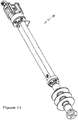
- Boom adaptor 24 preferably includes an insulated section which mounts onto the upper end of boom 22. This permits the use of non-insulated booms 22.
- a scissor-linkage 26 is interposed between boom adaptor 24 and beam or upper frame 28 which preferably consists of an elongated tube and is pivotally connected to the end of boom adaptor 24 by means of a pivot joint 30.
- Boom adaptor 24 is connected towards one end of upper frame 28.
- Actuator 32 extends between boom adaptor 24 and upper frame 28 and is mounted at one end to the upper frame 28 and at the other end to the elbow 26a of scissor-linkage 26 for adjusting the angular position of upper frame 28 within substantially a 160 degree range of motion within a substantially vertical plane. Extension and retraction the actuating rod 32a of actuator 32 is actuated by hydraulic cylinder 32b. Insulators 34 are mounted on upper frame 28 by means of pivoting hinges 28a. One or more insulators 34 may be mounted on each hinge 28a. Hinges 28a allow insulators 34 to be for example laid flat along on top of, and flush against upper frame 28.
- robotic arm 20 may, although this is not intended to be limiting, further include first and second telescoping arms 36, 38 which are telescopically coupled to opposite ends of upper frame 28.
- each telescoping arm 36, 38 is independently adjustable between a retracted position and an extended position coaxial with upper frame 28. Movement of telescoping arms 36, 38 is preferably actuated by hydraulic cylinders housed within upper frame 28. Alternatively, threaded rods powered by hydraulic motors, worm gears, or other suitable mechanical actuators could be employed.
- Insulators 34 are mounted as a parallel series or parallel array on the upper surface of upper frame 28 and may also be mounted on telescoping arms 36, 38 if telescoping arms are employed. Insulators may be mounted in pairs 34a, 34b and 34c or may be mounted singlely or in groups of more than two.
- a conductor holder 40 is mounted at the upper end of each insulator 34 for releasably coupling robotic arm 20 to a corresponding energized conductor.
- the number of insulators 34 and corresponding conductor holders required depends upon the number of transmission and/or distribution conductors in question. Further, the length of insulators 34, and the coupling together, for example on pairs, of more than one insulator 34, is determined by the mechanical arrangement of the conductors and the voltage level at which they are operating.
- the centre conductor of a three phase transmission line often extends above the two outside conductors.
- the centre insulator 34 that is, the insulator stack mounted between the ends of upper frame 28 may be longer in length than the insulator stacks mounted on the ends of the beam, for example on the ends of telescoping arms 36, 38 or an example may consist of two insulators 34 bolted together for extra length.
- Insulators 34 preferably consist of station class polymer insulators which are rated for all weather use.
- Robotic arm 20 is controlled remotely by an operator so as to control the angular position of upper frame 28 relative to the boom and boom adaptor, and the position of telescoping arms 36, 38 if they are included.
- the control system may consist of hydraulic hose (not shown) connected to the auxiliary port of the service vehicle hydraulic system and valving for controlling the operation of hydraulic cylinder 32b.
- the operation of hydraulic cylinder 32b may be remotely controlled by means of digital radio signals, fiber optic cables, or other suitable insulated control means.
- the remote operator may be positioned for example in a bucket secured to the service vehicle boom on transmission tower, on the deck of the service vehicle, or on the ground.
- robotic arm 20 is first mounted on boom 22 of the service vehicle described above.
- the hydraulic hoses (if any) are then connected to the auxiliary hydraulic part of the service vehicle.
- the service vehicle is typically parked immediately underneath or adjacent to the support tower to be serviced.
- the truck boom 22 is extended to position arm 20 underneath the energized transmission lines in question. If necessary, boom 22 may be rotated about the turret of the service vehicle until the desired angular position of the boom relative to the vehicle is reached.
- each conductor holder 40 may be rotatable about bearing adaptors for alignment with the corresponding conductor irrespective of the orientation of boom 22.
- the linemen manually unties the conductors from the insulator mounted on the tower crossarm.
- the conductors may then be raised wdl above the tower by extending boom 22.
- the outside conductor strands may be extended laterally away from the tower by either or both extending telescoping arms 36, 38 if provided, and inclining end insulators 34 outwardly of upper frame 28, by actuators which are independently controllable by actuating corresponding hydraulic cylinders such as would be mounted within on or upper frame 28, or by manually adjusting the extension and/or angling of the beam or insulators respectively.
- the distance between phases may be extended from, for example, two metres to four or four and a half metres (six feet to fourteen or fifteen feet) to provide linemen with safe working clearances even in the case of high voltage lines (for example greater than 100 kV).
- Robotic arm 20 temporarily supports the weight of the conductors to enable servicing of replacement of conductor support structures, such as the tower, instilators, or crossarms by the linemen.
- telescoping arms 36, 38 are retracted to thereby return the outer conductor strands to their original position.
- the truck boom 22 may then be lowered, if necessary, until upper frame 28 is positioned slightly below the level of the crossarm.
- the conductors are then retied by the linemen to the tower insulators and the conducting bolder latching mechanisms on insulators 34 are opened to complete the servicing procedure.
- an outside conductor strand could be connected to a corresponding connector holder 40 and insulator 34 mounted on the end of upper frame 28 or on a telescoping arm 36 or 38 while frame 28 is tilted at an angle or vertically, for example to pick up outside conductors which are spaced apart vertically on a tower.
- Telescoping arms 36, 38 could them be extended or the insulators angled away from the ends of upper frame 28 or arms 36, 38 to move the conductor a safe distance away from the tower to be serviced.
- robotic arm 20 could then be pivoted as described above until frame 28 is level with the tower crossarm. The remaining conductor lines could be then coupled to robotic arm 20, if necessary. This technique may be suitable, for example, if there is very little clearance between the transmission tower and surrounding structures.
- Distribution lines are often strung between support towers a short distance below transmission lines. Both transmission lines and distribution lines may be supported on insulators 34 on upper frame 28.
- the boom 22 When the boom truck moves from jobsite tojobsite, and for road travel, the boom 22 is retracted and laid flat down on the deck of the truck. To minimize the size of the retracted load, which includes the boom 22, upper frame 28, and insulators 34, it is advantageous if the upper frame 28 and insulators 34 fold down onto the boom 22 so that the load on the boom truck is as compact as possible.
- the upper frame 28 may be articulated across a large range of motion to thereby allow for situations where the boom truck has to park some distance out from under the conductors to be serviced so that the boom 22 is extended at a considerable angle off the vertical, as seen in figure 2 , especially where, in order to pick for example three vertically spaced apart conductors, the upper frame 28 has to be rotated to the vertical as seen in figure 1 .
- an increased range of motion of upper frame 28 relative to boom 22, is achieved by the use of scissor-linkage 26.
- the range of motion about pivot point 30 is indicated by angles "a" and ⁇ .
- Rigid linkage members 26b and 26c are pivotally pinned together at elbow 26a.
- the opposite ends of linkage members 26b and 26c are pivotally pinned at hinges 30a and 30b respectively, adjacent base end 28b of upper frame 28 and on the head 24a of boom adapter 24.
- Linkage members 26b, 26c may be substantially the same length.
- actuator 32 One end of actuator 32, illustrated to be the distal end of rod 32a (although this is not intended to be limiting), is pivotally mounted to elbow 26a.
- Pivot joint 30 and hinge 30a may be mounted to a pair of mounting plates 42, mounted one on each side of upper frame 28 at base end 28b.
- linkage members 26b and 26c are each a pair of parallel members spaced apart across the width of upper frame 28.
- Elbow 26a is a pin or shaft joining the common ends of the pairs of members.
- the distal end of rod 32a is mounted on the pin or shaft by collar 32c.
- the base end of cylinder 32b is mounted to upper frame 28 by a pair of plates 32d.
- angle ⁇ is approximately 20 degrees and angle a is approximately 160 degrees
- scissor linkage 26 is at its most-open, or almost most-open, separation between hinges 30a and 30b.
- actuator 32 When it is desired to rotate upper frame 28 from its vertical position seen in Figure 1 (that is, when in use the position to pick-up vertically spaced apart conductors), to its folded down position for storage and travel, actuator 32 is retracted thereby closing the separation of scissor linkage 26 as seen in the progression of Figures 2 and 3 .
- boom 22 has been lowered to horizontal, and the telescoping arms, if any, telescopically retracted if they were extended, so as to lay the boom down on the deck of the boom truck.
- Upper frame 28 lies substantially horizontally on and along boom 22.
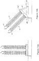
- Manually pivotable insulators 34 are folded down onto horizontal upper frame 28 by their pinned or bolted mounts being released, thereby releasing base ends 34d from corresponding pairs of hinge plates 44 mounted on opposite sides of upper frame 28 so that the base ends 34d may pivot about pivoting hinges 28a.
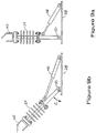
- insulators 34 are inclined by actuators such as actuation 46, illustrated by way of example in Figures 9a, 9b the insulators are laid flat or substantially flat by the actuations of actuators 46.
- the spacing between the base ends 34d is sufficient to allow an adjacent pair of insulators 34 to fold down into an end-to-end alignment such as seen in Figure 3 .
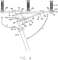
- Figures 4 and 5 show upper frame 28 in a horizontal position such as would be used to pick-up horizontally spaced apart conductors.
- Figure 5 shows the use of optional rigid extension members 46 mounted in oppositely disposed co-axial alignment to the opposite ends of telescoping arms 36, 38 or of upper frame 28 when arms 36,38 are not employed.
- Insulators 34 are mounted at the outermost ends of the extension members to provide for situations where the spacing between conductors is larger than the extendable range of telescoping arms 36 and 38 at their maximum extension from upper frame 28, including the extra range afforded by angling insulators 34 outwardly of the ends of the beam.
- Static picks 48 may be mounted to the main beam or upper frame 28 between the support posts or insulators 34 so as to extend substantially perpendicularly from the beam, and may also be mounted by second rotation couplings such as hinges 28a to, for example, pivot along the beam.
- Angular positioners such as actuators 46 may be mounted acting between the posts 34 and/or picks 48 for adjusting the inclination angle C of the posts or picks about the second rotation coupling on the beam.
- the angular positioners may be rigid positioners for example using links 29 of different lengths to selectively tip or pivot the posts or picks about their hinges 28a by set angles C such as for example 15°, 30°, 45°, etc.
- the hinges maybe selectively pivoted between their open-most and their closed positions, or otherwise the posts or picks may pivoted about their second rotational couplings.
- the second rotational couplings may also include pinned joints, rotational sleeves, shafts and bearings, universal joints, ball-joints, etc (not shown) as would be known to those skilled in the art.
- Actuators 46 may be for example hydraulic cylinders cooperating between the posts or picks and the beam.
- the support posts 34 may be single support posts 34 mounted one post per hinge 28a or pivot, or the support posts 34 may be multiple support posts, for example, pairs of support posts mounted one pair or group of support posts per hinge 28a or pivot
Landscapes
- Forklifts And Lifting Vehicles (AREA)
- Manipulator (AREA)
- Insulators (AREA)
- Electric Cable Installation (AREA)
- Operation Control Of Excavators (AREA)
- Jib Cranes (AREA)
Applications Claiming Priority (3)
| Application Number | Priority Date | Filing Date | Title |
|---|---|---|---|
| US13/374,057 US8684333B2 (en) | 2006-06-02 | 2011-12-09 | Boom mountable robotic arm |
| PCT/US2012/068729 WO2013086488A1 (en) | 2011-12-09 | 2012-12-10 | Boom mountable robotic arm |
| EP12856096.8A EP2789066B1 (en) | 2011-12-09 | 2012-12-10 | Boom mountable robotic arm |
Related Parent Applications (2)
| Application Number | Title | Priority Date | Filing Date |
|---|---|---|---|
| EP12856096.8A Division-Into EP2789066B1 (en) | 2011-12-09 | 2012-12-10 | Boom mountable robotic arm |
| EP12856096.8A Division EP2789066B1 (en) | 2011-12-09 | 2012-12-10 | Boom mountable robotic arm |
Publications (2)
| Publication Number | Publication Date |
|---|---|
| EP3247012A1 EP3247012A1 (en) | 2017-11-22 |
| EP3247012B1 true EP3247012B1 (en) | 2020-04-08 |
Family
ID=48574973
Family Applications (2)
| Application Number | Title | Priority Date | Filing Date |
|---|---|---|---|
| EP17180094.9A Active EP3247012B1 (en) | 2011-12-09 | 2012-12-10 | Boom mountable robotic arm |
| EP12856096.8A Active EP2789066B1 (en) | 2011-12-09 | 2012-12-10 | Boom mountable robotic arm |
Family Applications After (1)
| Application Number | Title | Priority Date | Filing Date |
|---|---|---|---|
| EP12856096.8A Active EP2789066B1 (en) | 2011-12-09 | 2012-12-10 | Boom mountable robotic arm |
Country Status (18)
| Country | Link |
|---|---|
| US (3) | US8684333B2 (no) |
| EP (2) | EP3247012B1 (no) |
| AR (1) | AR089131A1 (no) |
| AU (3) | AU2012347497B2 (no) |
| BR (1) | BR102012031478A2 (no) |
| CA (1) | CA2858745C (no) |
| CL (1) | CL2012002805A1 (no) |
| CO (1) | CO6920054A1 (no) |
| DK (2) | DK3247012T3 (no) |
| ES (2) | ES2797116T3 (no) |
| HK (1) | HK1245515A1 (no) |
| HR (1) | HRP20171730T1 (no) |
| NO (1) | NO2892620T3 (no) |
| PE (1) | PE20131176A1 (no) |
| PL (1) | PL2789066T3 (no) |
| PT (2) | PT2789066T (no) |
| WO (1) | WO2013086488A1 (no) |
| ZA (1) | ZA201702446B (no) |
Families Citing this family (24)
| Publication number | Priority date | Publication date | Assignee | Title |
|---|---|---|---|---|
| US8684333B2 (en) * | 2006-06-02 | 2014-04-01 | Quanta Associates, L.P. | Boom mountable robotic arm |
| PL2036179T3 (pl) * | 2006-06-02 | 2018-08-31 | Quanta Associates, L.P. | Zdalny manipulator do manipulowania grupą przewodów składowych w jednofazowej wiązce pod napięciem |
| CA2620970A1 (fr) * | 2008-01-31 | 2009-07-31 | Andre Lessard | Manipulateur portable pour effectuer des travaux sur des lignes electriques aeriennes sous tension |
| US20140008511A1 (en) * | 2012-07-06 | 2014-01-09 | Inveral, S.A. | Fall protection device |
| US9938117B2 (en) * | 2013-07-24 | 2018-04-10 | Fritel & Associates, LLC | Mobile conductor lift |
| WO2015131022A1 (en) * | 2014-02-28 | 2015-09-03 | Quanta Associates, L.P. | Stringing replacement wire near energized power lines |
| PE20171312A1 (es) * | 2014-05-08 | 2017-09-06 | Quanta Associates Lp | Soporte de conductor giratorio |
| EP2990796A1 (en) * | 2014-08-29 | 2016-03-02 | The Procter and Gamble Company | Device for testing the properties of hair fibres |
| AR108042A1 (es) | 2016-03-31 | 2018-07-11 | Quanta Associates Lp | Un sistema interruptor montable en grúa y un método para usarlo |
| CN105762702B (zh) * | 2016-04-01 | 2017-08-04 | 中国南方电网有限责任公司超高压输电公司南宁局 | 更换±800kV直流输电线路L串绝缘子的方法 |
| WO2018064754A1 (en) * | 2016-10-05 | 2018-04-12 | Hydro-Quebec | Resistance-measuring device and method |
| DE102017130190A1 (de) | 2017-12-15 | 2019-06-19 | Omexom Hochspannung Gmbh | Freileitungsträger und Verfahren zum Abnehmen einer Freileitung |
| RU2722177C1 (ru) * | 2019-05-07 | 2020-05-28 | ОАО "Сетевая компания" | ТРАВЕРСА И СПОСОБ ЗАМЕНЫ ОДНОСТОЕЧНОЙ ПРОМЕЖУТОЧНОЙ ОПОРЫ НА ВОЗДУШНОЙ ЛИНИИ ДО 1 кВ С НЕИЗОЛИРОВАННЫМИ ПРОВОДАМИ БЕЗ ОТКЛЮЧЕНИЯ ЭЛЕКТРОУСТАНОВКИ |
| CN111181065B (zh) * | 2020-01-13 | 2020-12-29 | 贵州大学 | 一种电力设备户外维护装置 |
| CA3074146A1 (en) | 2020-02-28 | 2021-08-28 | Quanta Associates, L.P. | Mounting a robotic arm in an inverted position to suspend an electrical bypass |
| US20210281052A1 (en) * | 2020-03-06 | 2021-09-09 | Wagner-Smith Equipment Co. | Mobile guard structure |
| CR20220459A (es) * | 2020-03-12 | 2022-11-15 | Quanta Associates Lp | Método y aparato para elevación de un haz de subconductores |
| US20220189710A1 (en) * | 2020-12-16 | 2022-06-16 | Cleaveland/Price Inc. | Unitized three phase switch with a power actuated transformable base and method for operation |
| CN112531569B (zh) * | 2020-12-29 | 2022-05-20 | 合肥中科国瑞智能科技有限公司 | 一种多足切换式线缆巡检机器人及其巡检方法 |
| US11575249B2 (en) * | 2021-01-13 | 2023-02-07 | Yantai Jereh Petroleum Equipment & Technologies Co., Ltd. | Cable laying device |
| US20220239076A1 (en) * | 2021-01-27 | 2022-07-28 | Quanta Associates, L.P. | Electrically insulated boom mountable temporary conductor guard structure |
| US11689008B1 (en) * | 2022-07-28 | 2023-06-27 | Altec Industries, Inc. | Wire tensioning system |
| US11749978B1 (en) * | 2022-07-28 | 2023-09-05 | Altec Industries, Inc. | Cross-arm phase-lifter |
| US11997429B2 (en) | 2022-07-28 | 2024-05-28 | Altec Industries, nc. | Reducing latency in head-mounted display for the remote operation of machinery |
Family Cites Families (54)
| Publication number | Priority date | Publication date | Assignee | Title |
|---|---|---|---|---|
| US60086A (en) * | 1866-11-27 | frackp | ||
| US800636A (en) * | 1904-07-01 | 1905-10-03 | Eugene M Fancher | Heat-shield for radiators. |
| US1580571A (en) * | 1921-12-05 | 1926-04-13 | Everedy Auto Jack Co | Jack |
| US2662730A (en) * | 1950-10-31 | 1953-12-15 | Wayne B Crawford | Power line lift pole |
| US3043394A (en) * | 1960-02-03 | 1962-07-10 | Mccabepowers Body Company | Boom attachments |
| US3005512A (en) * | 1960-05-31 | 1961-10-24 | Asplundh Tree Expert Co | Aerial supporting structure for line construction and maintenance workers |
| US3356413A (en) * | 1965-09-10 | 1967-12-05 | Bostrom Corp | Vehicle seat |
| US3631939A (en) * | 1970-05-08 | 1972-01-04 | Tel E Lect | Mobile aerial tower |
| AT309120B (de) * | 1970-11-23 | 1973-06-15 | Fahr Ag Maschf | Fahrzeug insbesondere landwirtschaftliches fahrzeug |
| US4194723A (en) * | 1978-04-14 | 1980-03-25 | Jlg Industries, Inc. | Scissors linkage workman's platform |
| US4353399A (en) * | 1980-02-01 | 1982-10-12 | Richard L. Harris | Multipurpose tool |
| US4466506A (en) | 1982-01-15 | 1984-08-21 | Dolenti Alfred N | Wire lift device for high tension electric line |
| US4502505A (en) * | 1982-09-24 | 1985-03-05 | Fmc Corporation | Telescoping boom supported clustered service line |
| US4852856A (en) * | 1988-01-05 | 1989-08-01 | Correll Daniel J | System for laying communications cable especially adapted for aerially stringing fiber optic cable and adapted for interchangeable use with conventional cable |
| CA1306220C (en) * | 1988-03-17 | 1992-08-11 | Paul Michaud | Articulated boom jib assembly |
| US5014863A (en) * | 1989-04-14 | 1991-05-14 | Iowa Mold Tooling Company, Inc. | Vehicle mounted crane |
| NL8901542A (nl) * | 1989-06-20 | 1991-01-16 | Verachtert Beheer Bv | Inrichting voor het stukmaken van uit beton of dergelijk materiaal bestaande voorwerpen. |
| IT1234767B (it) * | 1989-09-01 | 1992-05-26 | C M S S P A Costruzioni Macchi | Apparecchiatura per la movimentazione a distanza di una telecamera per riprese televisive speciali |
| US4973795A (en) | 1989-11-09 | 1990-11-27 | Sharpe Robert F | Temporary transmission hot line crossarm and method of replacing transmission hot line crossarms |
| US5076449A (en) * | 1990-02-26 | 1991-12-31 | A. B. Chance Company | Load measurement system for boom mounted auxiliary arm |
| US5183168A (en) * | 1990-09-05 | 1993-02-02 | Aichi Sharyo Co. Ltd. | Mobile vehicular apparatus with aerial cabin |
| US5268591A (en) * | 1990-09-21 | 1993-12-07 | Kabushiki Kaisha Aichi Corporation | Upper power supply arrangement for mobile vehicular apparatus with aerial platform |
| US5107954A (en) * | 1990-10-31 | 1992-04-28 | Aichi Sharyo Co. Ltd. | Control device for mobile vehicular apparatus with aerial platform |
| US5193897A (en) * | 1992-01-07 | 1993-03-16 | Halsey Keith D | Combined pen and light pointer apparatus |
| CA2134617C (en) | 1994-10-28 | 1998-01-06 | Daniel Neil O'connell | Boom-mountable robotic arm |
| US5601270A (en) * | 1995-10-12 | 1997-02-11 | Chen; Cheng-Sung | Paper holder on which a sheet of paper can be supported at different inclinations |
| US5791639A (en) * | 1995-11-27 | 1998-08-11 | Johnston; Russell M. | Framing member support stand |
| CA2268959C (en) | 1996-10-18 | 2005-07-26 | Kabushiki Kaisha Yaskawa Denki | Robot vehicle for hot-line job |
| US5944138A (en) * | 1997-09-03 | 1999-08-31 | Altec Industries, Inc. | Leveling system for aerial platforms |
| US6082552A (en) * | 1997-09-04 | 2000-07-04 | Gear Up Technologies Corporation | Wall-mounted storage device |
| US5934414A (en) * | 1998-01-07 | 1999-08-10 | Staczek; James J. | Lifting apparatus |
| US5941507A (en) * | 1998-07-02 | 1999-08-24 | Page; Douglas Monroe | Cable installation guide |
| IT1308714B1 (it) * | 1999-02-18 | 2002-01-10 | Icar Spa | Condensatore autorigenerabile perfezionato |
| US6286812B1 (en) * | 2000-03-27 | 2001-09-11 | Autoquip Corporation | Portable lifting apparatus |
| CA2357722C (en) * | 2000-09-22 | 2007-12-18 | Ok Champion Corporation | Articulated cable puller |
| CN100380758C (zh) * | 2001-06-11 | 2008-04-09 | 大原电机株式会社 | 电线杆内的换线装置和非掉电的配电方法 |
| US6702130B1 (en) * | 2001-07-02 | 2004-03-09 | James Donnie Carlilse | Door painting rack |
| US6837671B2 (en) | 2002-02-19 | 2005-01-04 | Clifford William Devine | Apparatus for precisely manipulating elongate objects adjacent to and such as energized overhead high voltage transmission lines |
| AU2003254259A1 (en) * | 2002-07-30 | 2004-02-16 | General Machine Products, Inc. | Aerial cable placing machine |
| EP1724891A3 (en) | 2003-08-29 | 2014-03-19 | Quanta Services | Live conductor stringing and splicing method and apparatus |
| US7281748B2 (en) * | 2005-04-11 | 2007-10-16 | Dura Global Technologies, Inc. | Tailgate lift-and-secure cable and latch assembly |
| EP1938159B1 (en) * | 2005-09-16 | 2016-08-24 | Ampacimon S.A. | Device, system and method for real-time monitoring of overhead power lines |
| US7546680B2 (en) * | 2006-01-10 | 2009-06-16 | Barthold Lionel O | Systems, methods and apparatus for transmission line re-conductoring |
| US8684333B2 (en) * | 2006-06-02 | 2014-04-01 | Quanta Associates, L.P. | Boom mountable robotic arm |
| PL2036179T3 (pl) | 2006-06-02 | 2018-08-31 | Quanta Associates, L.P. | Zdalny manipulator do manipulowania grupą przewodów składowych w jednofazowej wiązce pod napięciem |
| US7977571B2 (en) | 2006-08-30 | 2011-07-12 | Quanta Associates, L.P. | Method and apparatus for provision of temporary conductor tension support in transmission or distribution circuits |
| US7832709B2 (en) * | 2007-03-15 | 2010-11-16 | Cupertino Electric Inc. | Wire pulling apparatus |
| WO2008124579A1 (en) * | 2007-04-05 | 2008-10-16 | Barthold Lionel O | Apparatus and method for enhancing the reconductoring of overhead electric power lines |
| PL2149180T3 (pl) * | 2007-05-16 | 2015-04-30 | Quanta Associates Lp | Montowane na wysięgniku ramię robota |
| US20090095522A1 (en) * | 2007-10-12 | 2009-04-16 | Barthold Lionel O | Robotic Bypass System and Method |
| US8282111B2 (en) * | 2008-10-20 | 2012-10-09 | Magline, Inc. | Cart with movable platform |
| US20100123108A1 (en) * | 2008-11-14 | 2010-05-20 | Holley Woodrow W | Device for transferring a load from an object to a load-bearing element |
| US20100122490A1 (en) * | 2008-11-18 | 2010-05-20 | Paula Stewart | Apparatus for shielding plants from adverse weather conditions |
| US7954783B2 (en) * | 2009-03-17 | 2011-06-07 | Vigil Aurelio A | Folding bracket for light bar |
-
2011
- 2011-12-09 US US13/374,057 patent/US8684333B2/en active Active
-
2012
- 2012-10-05 CO CO12175776A patent/CO6920054A1/es active IP Right Grant
- 2012-10-05 PE PE2012001992A patent/PE20131176A1/es active IP Right Grant
- 2012-10-05 CL CL2012002805A patent/CL2012002805A1/es unknown
- 2012-12-10 ES ES17180094T patent/ES2797116T3/es active Active
- 2012-12-10 PT PT128560968T patent/PT2789066T/pt unknown
- 2012-12-10 DK DK17180094.9T patent/DK3247012T3/da active
- 2012-12-10 WO PCT/US2012/068729 patent/WO2013086488A1/en active Application Filing
- 2012-12-10 EP EP17180094.9A patent/EP3247012B1/en active Active
- 2012-12-10 PL PL12856096T patent/PL2789066T3/pl unknown
- 2012-12-10 PT PT171800949T patent/PT3247012T/pt unknown
- 2012-12-10 DK DK12856096.8T patent/DK2789066T3/da active
- 2012-12-10 CA CA2858745A patent/CA2858745C/en active Active
- 2012-12-10 AU AU2012347497A patent/AU2012347497B2/en active Active
- 2012-12-10 ES ES12856096.8T patent/ES2647518T3/es active Active
- 2012-12-10 BR BRBR102012031478-9A patent/BR102012031478A2/pt not_active Application Discontinuation
- 2012-12-10 EP EP12856096.8A patent/EP2789066B1/en active Active
- 2012-12-10 AR ARP120104625A patent/AR089131A1/es active IP Right Grant
-
2013
- 2013-09-09 NO NO13765580A patent/NO2892620T3/no unknown
- 2013-11-03 US US14/070,555 patent/US9112338B2/en active Active
-
2014
- 2014-03-31 US US14/231,280 patent/US9203219B2/en active Active
-
2017
- 2017-04-07 ZA ZA2017/02446A patent/ZA201702446B/en unknown
- 2017-04-18 AU AU2017202498A patent/AU2017202498B2/en active Active
- 2017-11-13 HR HRP20171730TT patent/HRP20171730T1/hr unknown
-
2018
- 2018-04-17 HK HK18104953.7A patent/HK1245515A1/zh unknown
-
2019
- 2019-04-24 AU AU2019202859A patent/AU2019202859B2/en active Active
Non-Patent Citations (1)
| Title |
|---|
| None * |
Also Published As
Similar Documents
| Publication | Publication Date | Title |
|---|---|---|
| AU2019202859B2 (en) | Boom mountable robotic arm | |
| EP2814125B1 (en) | Boom mountable robotic arm | |
| US5538207A (en) | Boom-mountable robotic arm | |
| CA3161545A1 (en) | Mounting a robotic arm in an inverted position to suspend an electrical bypass | |
| NZ626989B2 (en) | Boom mountable robotic arm |
Legal Events
| Date | Code | Title | Description |
|---|---|---|---|
| PUAI | Public reference made under article 153(3) epc to a published international application that has entered the european phase |
Free format text: ORIGINAL CODE: 0009012 |
|
| STAA | Information on the status of an ep patent application or granted ep patent |
Free format text: STATUS: REQUEST FOR EXAMINATION WAS MADE |
|
| 17P | Request for examination filed |
Effective date: 20170706 |
|
| AC | Divisional application: reference to earlier application |
Ref document number: 2789066 Country of ref document: EP Kind code of ref document: P |
|
| AK | Designated contracting states |
Kind code of ref document: A1 Designated state(s): AL AT BE BG CH CY CZ DE DK EE ES FI FR GB GR HR HU IE IS IT LI LT LU LV MC MK MT NL NO PL PT RO RS SE SI SK SM TR |
|
| AX | Request for extension of the european patent |
Extension state: BA ME |
|
| REG | Reference to a national code |
Ref country code: HK Ref legal event code: DE Ref document number: 1245515 Country of ref document: HK |
|
| GRAP | Despatch of communication of intention to grant a patent |
Free format text: ORIGINAL CODE: EPIDOSNIGR1 |
|
| STAA | Information on the status of an ep patent application or granted ep patent |
Free format text: STATUS: GRANT OF PATENT IS INTENDED |
|
| INTG | Intention to grant announced |
Effective date: 20190513 |
|
| GRAJ | Information related to disapproval of communication of intention to grant by the applicant or resumption of examination proceedings by the epo deleted |
Free format text: ORIGINAL CODE: EPIDOSDIGR1 |
|
| STAA | Information on the status of an ep patent application or granted ep patent |
Free format text: STATUS: REQUEST FOR EXAMINATION WAS MADE |
|
| INTC | Intention to grant announced (deleted) | ||
| GRAP | Despatch of communication of intention to grant a patent |
Free format text: ORIGINAL CODE: EPIDOSNIGR1 |
|
| STAA | Information on the status of an ep patent application or granted ep patent |
Free format text: STATUS: GRANT OF PATENT IS INTENDED |
|
| INTG | Intention to grant announced |
Effective date: 20191023 |
|
| GRAS | Grant fee paid |
Free format text: ORIGINAL CODE: EPIDOSNIGR3 |
|
| GRAA | (expected) grant |
Free format text: ORIGINAL CODE: 0009210 |
|
| STAA | Information on the status of an ep patent application or granted ep patent |
Free format text: STATUS: THE PATENT HAS BEEN GRANTED |
|
| AC | Divisional application: reference to earlier application |
Ref document number: 2789066 Country of ref document: EP Kind code of ref document: P |
|
| AK | Designated contracting states |
Kind code of ref document: B1 Designated state(s): AL AT BE BG CH CY CZ DE DK EE ES FI FR GB GR HR HU IE IS IT LI LT LU LV MC MK MT NL NO PL PT RO RS SE SI SK SM TR |
|
| REG | Reference to a national code |
Ref country code: CH Ref legal event code: EP Ref country code: AT Ref legal event code: REF Ref document number: 1255637 Country of ref document: AT Kind code of ref document: T Effective date: 20200415 |
|
| REG | Reference to a national code |
Ref country code: DE Ref legal event code: R096 Ref document number: 602012069236 Country of ref document: DE |
|
| REG | Reference to a national code |
Ref country code: IE Ref legal event code: FG4D |
|
| REG | Reference to a national code |
Ref country code: NL Ref legal event code: FP |
|
| REG | Reference to a national code |
Ref country code: SE Ref legal event code: TRGR |
|
| REG | Reference to a national code |
Ref country code: PT Ref legal event code: SC4A Ref document number: 3247012 Country of ref document: PT Date of ref document: 20200710 Kind code of ref document: T Free format text: AVAILABILITY OF NATIONAL TRANSLATION Effective date: 20200703 |
|
| REG | Reference to a national code |
Ref country code: DK Ref legal event code: T3 Effective date: 20200708 |
|
| REG | Reference to a national code |
Ref country code: NO Ref legal event code: T2 Effective date: 20200408 |
|
| REG | Reference to a national code |
Ref country code: LT Ref legal event code: MG4D |
|
| REG | Reference to a national code |
Ref country code: HK Ref legal event code: WD Ref document number: 1245515 Country of ref document: HK |
|
| PG25 | Lapsed in a contracting state [announced via postgrant information from national office to epo] |
Ref country code: IS Free format text: LAPSE BECAUSE OF FAILURE TO SUBMIT A TRANSLATION OF THE DESCRIPTION OR TO PAY THE FEE WITHIN THE PRESCRIBED TIME-LIMIT Effective date: 20200808 Ref country code: FI Free format text: LAPSE BECAUSE OF FAILURE TO SUBMIT A TRANSLATION OF THE DESCRIPTION OR TO PAY THE FEE WITHIN THE PRESCRIBED TIME-LIMIT Effective date: 20200408 Ref country code: LT Free format text: LAPSE BECAUSE OF FAILURE TO SUBMIT A TRANSLATION OF THE DESCRIPTION OR TO PAY THE FEE WITHIN THE PRESCRIBED TIME-LIMIT Effective date: 20200408 Ref country code: GR Free format text: LAPSE BECAUSE OF FAILURE TO SUBMIT A TRANSLATION OF THE DESCRIPTION OR TO PAY THE FEE WITHIN THE PRESCRIBED TIME-LIMIT Effective date: 20200709 |
|
| PG25 | Lapsed in a contracting state [announced via postgrant information from national office to epo] |
Ref country code: BG Free format text: LAPSE BECAUSE OF FAILURE TO SUBMIT A TRANSLATION OF THE DESCRIPTION OR TO PAY THE FEE WITHIN THE PRESCRIBED TIME-LIMIT Effective date: 20200708 Ref country code: HR Free format text: LAPSE BECAUSE OF FAILURE TO SUBMIT A TRANSLATION OF THE DESCRIPTION OR TO PAY THE FEE WITHIN THE PRESCRIBED TIME-LIMIT Effective date: 20200408 Ref country code: RS Free format text: LAPSE BECAUSE OF FAILURE TO SUBMIT A TRANSLATION OF THE DESCRIPTION OR TO PAY THE FEE WITHIN THE PRESCRIBED TIME-LIMIT Effective date: 20200408 Ref country code: LV Free format text: LAPSE BECAUSE OF FAILURE TO SUBMIT A TRANSLATION OF THE DESCRIPTION OR TO PAY THE FEE WITHIN THE PRESCRIBED TIME-LIMIT Effective date: 20200408 |
|
| REG | Reference to a national code |
Ref country code: ES Ref legal event code: FG2A Ref document number: 2797116 Country of ref document: ES Kind code of ref document: T3 Effective date: 20201201 |
|
| PG25 | Lapsed in a contracting state [announced via postgrant information from national office to epo] |
Ref country code: AL Free format text: LAPSE BECAUSE OF FAILURE TO SUBMIT A TRANSLATION OF THE DESCRIPTION OR TO PAY THE FEE WITHIN THE PRESCRIBED TIME-LIMIT Effective date: 20200408 |
|
| REG | Reference to a national code |
Ref country code: DE Ref legal event code: R097 Ref document number: 602012069236 Country of ref document: DE |
|
| REG | Reference to a national code |
Ref country code: AT Ref legal event code: UEP Ref document number: 1255637 Country of ref document: AT Kind code of ref document: T Effective date: 20200408 |
|
| PG25 | Lapsed in a contracting state [announced via postgrant information from national office to epo] |
Ref country code: RO Free format text: LAPSE BECAUSE OF FAILURE TO SUBMIT A TRANSLATION OF THE DESCRIPTION OR TO PAY THE FEE WITHIN THE PRESCRIBED TIME-LIMIT Effective date: 20200408 Ref country code: IT Free format text: LAPSE BECAUSE OF FAILURE TO SUBMIT A TRANSLATION OF THE DESCRIPTION OR TO PAY THE FEE WITHIN THE PRESCRIBED TIME-LIMIT Effective date: 20200408 Ref country code: EE Free format text: LAPSE BECAUSE OF FAILURE TO SUBMIT A TRANSLATION OF THE DESCRIPTION OR TO PAY THE FEE WITHIN THE PRESCRIBED TIME-LIMIT Effective date: 20200408 Ref country code: SM Free format text: LAPSE BECAUSE OF FAILURE TO SUBMIT A TRANSLATION OF THE DESCRIPTION OR TO PAY THE FEE WITHIN THE PRESCRIBED TIME-LIMIT Effective date: 20200408 Ref country code: CZ Free format text: LAPSE BECAUSE OF FAILURE TO SUBMIT A TRANSLATION OF THE DESCRIPTION OR TO PAY THE FEE WITHIN THE PRESCRIBED TIME-LIMIT Effective date: 20200408 |
|
| PLBE | No opposition filed within time limit |
Free format text: ORIGINAL CODE: 0009261 |
|
| STAA | Information on the status of an ep patent application or granted ep patent |
Free format text: STATUS: NO OPPOSITION FILED WITHIN TIME LIMIT |
|
| PG25 | Lapsed in a contracting state [announced via postgrant information from national office to epo] |
Ref country code: PL Free format text: LAPSE BECAUSE OF FAILURE TO SUBMIT A TRANSLATION OF THE DESCRIPTION OR TO PAY THE FEE WITHIN THE PRESCRIBED TIME-LIMIT Effective date: 20200408 Ref country code: SK Free format text: LAPSE BECAUSE OF FAILURE TO SUBMIT A TRANSLATION OF THE DESCRIPTION OR TO PAY THE FEE WITHIN THE PRESCRIBED TIME-LIMIT Effective date: 20200408 |
|
| 26N | No opposition filed |
Effective date: 20210112 |
|
| PG25 | Lapsed in a contracting state [announced via postgrant information from national office to epo] |
Ref country code: SI Free format text: LAPSE BECAUSE OF FAILURE TO SUBMIT A TRANSLATION OF THE DESCRIPTION OR TO PAY THE FEE WITHIN THE PRESCRIBED TIME-LIMIT Effective date: 20200408 |
|
| REG | Reference to a national code |
Ref country code: CH Ref legal event code: PL |
|
| PG25 | Lapsed in a contracting state [announced via postgrant information from national office to epo] |
Ref country code: MC Free format text: LAPSE BECAUSE OF FAILURE TO SUBMIT A TRANSLATION OF THE DESCRIPTION OR TO PAY THE FEE WITHIN THE PRESCRIBED TIME-LIMIT Effective date: 20200408 |
|
| PG25 | Lapsed in a contracting state [announced via postgrant information from national office to epo] |
Ref country code: LU Free format text: LAPSE BECAUSE OF NON-PAYMENT OF DUE FEES Effective date: 20201210 |
|
| PG25 | Lapsed in a contracting state [announced via postgrant information from national office to epo] |
Ref country code: CH Free format text: LAPSE BECAUSE OF NON-PAYMENT OF DUE FEES Effective date: 20201231 Ref country code: LI Free format text: LAPSE BECAUSE OF NON-PAYMENT OF DUE FEES Effective date: 20201231 |
|
| PG25 | Lapsed in a contracting state [announced via postgrant information from national office to epo] |
Ref country code: TR Free format text: LAPSE BECAUSE OF FAILURE TO SUBMIT A TRANSLATION OF THE DESCRIPTION OR TO PAY THE FEE WITHIN THE PRESCRIBED TIME-LIMIT Effective date: 20200408 Ref country code: MT Free format text: LAPSE BECAUSE OF FAILURE TO SUBMIT A TRANSLATION OF THE DESCRIPTION OR TO PAY THE FEE WITHIN THE PRESCRIBED TIME-LIMIT Effective date: 20200408 Ref country code: CY Free format text: LAPSE BECAUSE OF FAILURE TO SUBMIT A TRANSLATION OF THE DESCRIPTION OR TO PAY THE FEE WITHIN THE PRESCRIBED TIME-LIMIT Effective date: 20200408 |
|
| PG25 | Lapsed in a contracting state [announced via postgrant information from national office to epo] |
Ref country code: MK Free format text: LAPSE BECAUSE OF FAILURE TO SUBMIT A TRANSLATION OF THE DESCRIPTION OR TO PAY THE FEE WITHIN THE PRESCRIBED TIME-LIMIT Effective date: 20200408 |
|
| P01 | Opt-out of the competence of the unified patent court (upc) registered |
Effective date: 20230414 |
|
| P02 | Opt-out of the competence of the unified patent court (upc) changed |
Effective date: 20230514 |
|
| PGFP | Annual fee paid to national office [announced via postgrant information from national office to epo] |
Ref country code: GB Payment date: 20231227 Year of fee payment: 12 |
|
| PGFP | Annual fee paid to national office [announced via postgrant information from national office to epo] |
Ref country code: SE Payment date: 20231227 Year of fee payment: 12 Ref country code: PT Payment date: 20231123 Year of fee payment: 12 Ref country code: NO Payment date: 20231227 Year of fee payment: 12 Ref country code: NL Payment date: 20231226 Year of fee payment: 12 Ref country code: IE Payment date: 20231227 Year of fee payment: 12 Ref country code: FR Payment date: 20231227 Year of fee payment: 12 Ref country code: DK Payment date: 20231229 Year of fee payment: 12 Ref country code: AT Payment date: 20231121 Year of fee payment: 12 |
|
| PGFP | Annual fee paid to national office [announced via postgrant information from national office to epo] |
Ref country code: BE Payment date: 20231227 Year of fee payment: 12 |
|
| PGFP | Annual fee paid to national office [announced via postgrant information from national office to epo] |
Ref country code: ES Payment date: 20240102 Year of fee payment: 12 |
|
| PGFP | Annual fee paid to national office [announced via postgrant information from national office to epo] |
Ref country code: DE Payment date: 20231229 Year of fee payment: 12 |