EP3246712B1 - Adaptive filtering system for aerodynamic angles of an aircraft - Google Patents
Adaptive filtering system for aerodynamic angles of an aircraft Download PDFInfo
- Publication number
- EP3246712B1 EP3246712B1 EP17170925.6A EP17170925A EP3246712B1 EP 3246712 B1 EP3246712 B1 EP 3246712B1 EP 17170925 A EP17170925 A EP 17170925A EP 3246712 B1 EP3246712 B1 EP 3246712B1
- Authority
- EP
- European Patent Office
- Prior art keywords
- change
- rate
- angle
- inertial
- aerodynamic angle
- Prior art date
- Legal status (The legal status is an assumption and is not a legal conclusion. Google has not performed a legal analysis and makes no representation as to the accuracy of the status listed.)
- Active
Links
- 230000003044 adaptive effect Effects 0.000 title description 2
- 238000001914 filtration Methods 0.000 title description 2
- 230000008859 change Effects 0.000 claims description 194
- 238000001514 detection method Methods 0.000 claims description 50
- 238000000034 method Methods 0.000 claims description 44
- 238000005259 measurement Methods 0.000 claims description 25
- 230000002459 sustained effect Effects 0.000 claims description 15
- 238000012545 processing Methods 0.000 claims description 12
- 230000001141 propulsive effect Effects 0.000 claims description 10
- 230000000694 effects Effects 0.000 claims description 6
- 230000003247 decreasing effect Effects 0.000 claims 2
- 230000008569 process Effects 0.000 description 19
- 238000004519 manufacturing process Methods 0.000 description 15
- 238000010586 diagram Methods 0.000 description 13
- 230000006870 function Effects 0.000 description 8
- 238000012423 maintenance Methods 0.000 description 5
- 230000010354 integration Effects 0.000 description 4
- 230000004048 modification Effects 0.000 description 4
- 238000012986 modification Methods 0.000 description 4
- 230000009471 action Effects 0.000 description 3
- 238000004891 communication Methods 0.000 description 3
- 239000003381 stabilizer Substances 0.000 description 3
- RZVHIXYEVGDQDX-UHFFFAOYSA-N 9,10-anthraquinone Chemical compound C1=CC=C2C(=O)C3=CC=CC=C3C(=O)C2=C1 RZVHIXYEVGDQDX-UHFFFAOYSA-N 0.000 description 2
- 238000006243 chemical reaction Methods 0.000 description 2
- 230000000295 complement effect Effects 0.000 description 2
- 238000013461 design Methods 0.000 description 2
- 238000009419 refurbishment Methods 0.000 description 2
- 238000005070 sampling Methods 0.000 description 2
- 230000003111 delayed effect Effects 0.000 description 1
- 238000005516 engineering process Methods 0.000 description 1
- 230000007613 environmental effect Effects 0.000 description 1
- 230000004927 fusion Effects 0.000 description 1
- 238000007726 management method Methods 0.000 description 1
- 239000000463 material Substances 0.000 description 1
- 230000008520 organization Effects 0.000 description 1
- 230000002085 persistent effect Effects 0.000 description 1
- 230000009467 reduction Effects 0.000 description 1
- 230000004044 response Effects 0.000 description 1
- 230000002441 reversible effect Effects 0.000 description 1
- 239000004065 semiconductor Substances 0.000 description 1
- 230000001960 triggered effect Effects 0.000 description 1
Images


Classifications
-
- B—PERFORMING OPERATIONS; TRANSPORTING
- B64—AIRCRAFT; AVIATION; COSMONAUTICS
- B64C—AEROPLANES; HELICOPTERS
- B64C13/00—Control systems or transmitting systems for actuating flying-control surfaces, lift-increasing flaps, air brakes, or spoilers
-
- G—PHYSICS
- G05—CONTROLLING; REGULATING
- G05D—SYSTEMS FOR CONTROLLING OR REGULATING NON-ELECTRIC VARIABLES
- G05D1/00—Control of position, course, altitude or attitude of land, water, air or space vehicles, e.g. using automatic pilots
- G05D1/08—Control of attitude, i.e. control of roll, pitch, or yaw
- G05D1/0808—Control of attitude, i.e. control of roll, pitch, or yaw specially adapted for aircraft
- G05D1/0816—Control of attitude, i.e. control of roll, pitch, or yaw specially adapted for aircraft to ensure stability
- G05D1/0825—Control of attitude, i.e. control of roll, pitch, or yaw specially adapted for aircraft to ensure stability using mathematical models
-
- B—PERFORMING OPERATIONS; TRANSPORTING
- B64—AIRCRAFT; AVIATION; COSMONAUTICS
- B64C—AEROPLANES; HELICOPTERS
- B64C13/00—Control systems or transmitting systems for actuating flying-control surfaces, lift-increasing flaps, air brakes, or spoilers
- B64C13/02—Initiating means
- B64C13/16—Initiating means actuated automatically, e.g. responsive to gust detectors
- B64C13/18—Initiating means actuated automatically, e.g. responsive to gust detectors using automatic pilot
-
- B—PERFORMING OPERATIONS; TRANSPORTING
- B64—AIRCRAFT; AVIATION; COSMONAUTICS
- B64D—EQUIPMENT FOR FITTING IN OR TO AIRCRAFT; FLIGHT SUITS; PARACHUTES; ARRANGEMENT OR MOUNTING OF POWER PLANTS OR PROPULSION TRANSMISSIONS IN AIRCRAFT
- B64D43/00—Arrangements or adaptations of instruments
- B64D43/02—Arrangements or adaptations of instruments for indicating aircraft speed or stalling conditions
-
- B—PERFORMING OPERATIONS; TRANSPORTING
- B64—AIRCRAFT; AVIATION; COSMONAUTICS
- B64D—EQUIPMENT FOR FITTING IN OR TO AIRCRAFT; FLIGHT SUITS; PARACHUTES; ARRANGEMENT OR MOUNTING OF POWER PLANTS OR PROPULSION TRANSMISSIONS IN AIRCRAFT
- B64D47/00—Equipment not otherwise provided for
-
- G—PHYSICS
- G01—MEASURING; TESTING
- G01P—MEASURING LINEAR OR ANGULAR SPEED, ACCELERATION, DECELERATION, OR SHOCK; INDICATING PRESENCE, ABSENCE, OR DIRECTION, OF MOVEMENT
- G01P13/00—Indicating or recording presence, absence, or direction, of movement
- G01P13/02—Indicating direction only, e.g. by weather vane
- G01P13/025—Indicating direction only, e.g. by weather vane indicating air data, i.e. flight variables of an aircraft, e.g. angle of attack, side slip, shear, yaw
-
- G—PHYSICS
- G05—CONTROLLING; REGULATING
- G05B—CONTROL OR REGULATING SYSTEMS IN GENERAL; FUNCTIONAL ELEMENTS OF SUCH SYSTEMS; MONITORING OR TESTING ARRANGEMENTS FOR SUCH SYSTEMS OR ELEMENTS
- G05B13/00—Adaptive control systems, i.e. systems automatically adjusting themselves to have a performance which is optimum according to some preassigned criterion
-
- G—PHYSICS
- G05—CONTROLLING; REGULATING
- G05D—SYSTEMS FOR CONTROLLING OR REGULATING NON-ELECTRIC VARIABLES
- G05D1/00—Control of position, course, altitude or attitude of land, water, air or space vehicles, e.g. using automatic pilots
-
- G—PHYSICS
- G06—COMPUTING; CALCULATING OR COUNTING
- G06F—ELECTRIC DIGITAL DATA PROCESSING
- G06F17/00—Digital computing or data processing equipment or methods, specially adapted for specific functions
- G06F17/40—Data acquisition and logging
-
- B—PERFORMING OPERATIONS; TRANSPORTING
- B64—AIRCRAFT; AVIATION; COSMONAUTICS
- B64U—UNMANNED AERIAL VEHICLES [UAV]; EQUIPMENT THEREFOR
- B64U10/00—Type of UAV
- B64U10/25—Fixed-wing aircraft
Definitions
- the present disclosure relates generally to aircraft and, in particular, to a method and apparatus for operating an aircraft. Still more particularly, the present disclosure relates to a method and apparatus for more accurately identifying aerodynamic angles used to operate the aircraft.
- a pilot receives information about the state of the aircraft. This information is used to make changes in the flight of the aircraft. For example, one type of information received is an angle of attack.
- the angle of attack affects the amount of lift that a wing provides the aircraft. For example, as the angle of attack increases, the lift increases up to a maximum lift coefficient. The angle of attack with the maximum lift coefficient is called the stall angle of attack.
- the angle at which the aircraft may stall is when the angle of attack is greater than the stall angle of attack.
- the angle of attack is used to provide information and alerts on the flight deck to improve flight crew awareness of airplane state relative to performance limits.
- US 6,273,370 B1 discloses a method and system for using inertial sensors in an Inertial Navigation System (INS) to obtain analytic estimates of angle-of-attack and sideslip angle.
- the inertial sensors consist of one or more accelerometers which produce the estimated signals for angle-of-attack and sideslip angle.
- EP 0 742 142 A2 discloses a method and apparatus for reducing the unwanted sideways motion of an airplane by reducing the lateral side loads and upsets caused by atmospheric turbulence and gusts.
- An embodiment of the present disclosure provides an apparatus comprising an aerodynamic angle detection system.
- the aerodynamic angle detection system calculates a first rate of change in an inertial aerodynamic angle for an aircraft using data received from an inertial measurement system for the aircraft. Further, the aerodynamic angle detection system calculates a second rate of change in an externally measured aerodynamic angle for the aircraft. Yet further, the aerodynamic angle detection system generates a filtered aerodynamic angle during flight of the aircraft using the first rate of change in the inertial aerodynamic angle and the second rate of change in the externally measured aerodynamic angle.
- the aerodynamic angle detection system changes a contribution of the first rate of change in the inertial aerodynamic angle used in generating the filtered aerodynamic angle based on a difference between the first rate of change in the inertial aerodynamic angle and the second rate of change in the externally measured aerodynamic angle, enabling controlling the flight of the aircraft using the filtered aerodynamic angle.
- the aerodynamic angle detection system comprises a first rate of change identifier, a second rate of change identifier, a decay identifier, an adjuster, and a filter.
- the first rate of change identifier calculates a first rate of change in an inertial aerodynamic angle for an aircraft using data received from an inertial measurement system for the aircraft and a filtered aerodynamic angle.
- the second rate of change identifier calculates a second rate of change in an externally measured aerodynamic angle for the aircraft.
- the decay identifier identifies a decay value based on a difference between the first rate of change in the inertial aerodynamic angle and the second rate of change in the externally measured aerodynamic angle, enabling controlling a flight of the aircraft using the filtered aerodynamic angle.
- the adjuster adjusts a contribution of the first rate of change in the inertial aerodynamic angle to form an adjusted contribution.
- the filter generates the filtered aerodynamic angle during the flight of the aircraft using the adjusted contribution as adjusted by the adjuster and the externally measured aerodynamic angle, enabling controlling the flight of the aircraft using the filtered aerodynamic angle.
- Yet another embodiment of the present disclosure provides a method for processing aerodynamic angles for an aircraft.
- a first rate of change in an inertial aerodynamic angle is calculated for the aircraft using data received from an inertial measurement system for the aircraft and a filtered aerodynamic angle.
- a second rate of change in an externally measured aerodynamic angle is calculated for the aircraft.
- the filtered aerodynamic angle is generated during a flight of the aircraft using the first rate of change in the inertial aerodynamic angle and the second rate of change in the externally measured aerodynamic angle.
- a contribution of the first rate of change in the inertial aerodynamic angle used in generated the filtered aerodynamic angle is changed based on a difference between the first rate of change in the inertial aerodynamic angle and the second rate of change in the externally measured aerodynamic angle, enabling controlling the flight of the aircraft using the filtered aerodynamic angle.
- the illustrative embodiments recognize and take into account one or more different considerations. For example, the illustrative embodiments recognize and take into account that current filters for aerodynamic angles, such as an angle of attack and a sideslip angle, do not filter noise from transitory turbulence and simultaneously react to sustained wind gusts as quickly and accurately as desired to operate an aircraft.
- current filters for aerodynamic angles such as an angle of attack and a sideslip angle
- first order lag filters used in aircraft to identify angles of attack and sideslip angles may filter out noise from the transitory turbulence, but have a delayed reaction in indicating changes in these angles when sustained gusts of wind are encountered.
- a delay or lag may not provide information about these angles as quickly and accurately as desired for an autopilot and flight control system to make needed changes to the flight of the aircraft or for a stall warning system to be triggered as quickly and accurately as desired.
- the illustrative embodiments also recognize and take into account that currently used complementary filters may provide a desired response to the transitory turbulence by using an internally sensed angle of attack. However, these types of filters are unable to capture rapid changes, such as those from sustained wind gusts.
- the illustrative embodiments provide a method and apparatus for sending data about aerodynamic angles with a reduction in noise from transitory turbulence and quick and accurate enough reactions to sustained wind gusts.
- a first rate of change in an inertial aerodynamic angle for the aircraft is calculated using data received from an inertial measurement system for the aircraft.
- a second rate of change in an externally measured aerodynamic angle for the aircraft is calculated.
- a filtered aerodynamic angle is generated during a flight of the aircraft using the first rate of change in the inertial aerodynamic angle and the second rate of change in the externally measured aerodynamic angle.
- a contribution of the first rate of change in the inertial aerodynamic angle used in generating the filtered aerodynamic angle is changed based on a difference between the first rate of change in the inertial aerodynamic angle and the second rate of change in the externally measured aerodynamic angle, enabling controlling the flight of the aircraft using the filtered aerodynamic angle.
- aircraft 100 has wing 102 and wing 104 attached to body 106 .
- Aircraft 100 includes engine 108 attached to wing 102 and engine 110 attached to wing 104 .
- Body 106 has tail section 112. Horizontal stabilizer 114, horizontal stabilizer 116, and vertical stabilizer 118 are attached to tail section 112 of body 106.
- Aircraft 100 is an example of an aircraft in which an aerodynamic angle detection system may be implemented in accordance with an illustrative embodiment.
- the aerodynamic angle detection system provides information about aerodynamic angles for use by different data processing systems in aircraft 100 in a manner that reduces noise and lags in identifying the aerodynamic angles.
- the noise and lags are caused by the manner in which wind changes with respect to an aircraft.
- the noise may be caused by transitory turbulence.
- the lag in identifying an aerodynamic angle may be caused by a sustained wind gust.
- transitory turbulence may occur when a gust of wind around an average wind is encountered by an aircraft. This gust of wind is continuous but varies randomly in time and space. The average wind is calculated by summing wind speed at sampling points within a period of time divided by the number of sampling points.
- a sustained gust of wind is an average wind with a speed that changes over time.
- a gust of wind may change suddenly or gradually with time and space due to wind shear and temperature gradients.
- aerodynamic angle detection environment 200 includes aerodynamic angle detection system 202 that is associated with aircraft 204.
- Aircraft 100 in Figure 1 is an example of a physical implementation of aircraft 204.
- Aircraft 204 is selected from one of an airplane, a commercial airplane, a vertical takeoff and landing aircraft, an unmanned aerial vehicle, a rotorcraft, or some other suitable type of aircraft.
- aerodynamic angle detection system 202 identifies filtered aerodynamic angle 206 for aircraft 204 during flight of aircraft 204.
- An aerodynamic angle is an angle of airflow relative to aircraft 204.
- the aerodynamic angle may be selected from one of an angle of attack, a sideslip angle, or some other angle that is the angle of airflow relative to aircraft 204.
- Filtered aerodynamic angle 206 is an output generated by aerodynamic angle detection system 202 using data 208 from sensor system 210 in aircraft 204.
- sensor system 210 may make measurements externally to aircraft 204, internal measurements regarding the state of aircraft 204, and the environment around aircraft 204.
- aerodynamic angle detection system 202 calculates first rate of change 212 in inertial aerodynamic angle 214 for aircraft 204 using data 208 received from inertial measurement system 216 in sensor system 210 for aircraft 204. Aerodynamic angle detection system 202 calculates second rate of change 218 in externally measured aerodynamic angle 220 for aircraft 204 using data 208 received from air data measurement system 217 in sensor system 210.
- Aerodynamic angle detection system 202 generates filtered aerodynamic angle 206 during a flight of aircraft 204 using first rate of change 212 in inertial aerodynamic angle 214 and second rate of change 218 in externally measured aerodynamic angle 220. Contribution 222 of first rate of change 212 in inertial aerodynamic angle 214 used in generating filtered aerodynamic angle 206 is changed based on a difference between first rate of change 212 in inertial aerodynamic angle 214 and second rate of change 218 in externally measured aerodynamic angle 220. These operations performed by aerodynamic angle detection system 202 enable controlling the flight of aircraft 204 using filtered aerodynamic angle 206.
- Aerodynamic angle detection system 202 calculates first rate of change 212 in inertial aerodynamic angle 214 for aircraft 204 using data 208 received from inertial measurement system 216 for aircraft 204 and changes the contribution of first rate of change 212 in inertial aerodynamic angle 214 to the filtered aerodynamic angle 206.
- Filtered aerodynamic angle 206 is used as a feedback to dynamically adjust first rate of change 212 in inertial aerodynamic angle 214.
- Contribution 222 of first rate of change 212 in inertial aerodynamic angle 214 may be changed to reduce an effect of at least one of a sustained gust of wind, a transitory turbulence, or some other undesired effect.
- Aerodynamic angle detection system 202 may be implemented in software, hardware, firmware, or a combination thereof.
- the operations performed by aerodynamic angle detection system 202 may be implemented in program code configured to run on hardware, such as a processor unit.
- firmware the operations performed by aerodynamic angle detection system 202 may be implemented in program code and data and stored in persistent memory to run on a processor unit.
- the hardware may include circuits that operate to perform the operations in aerodynamic angle detection system 202.
- the hardware may take a form selected from at least one of a circuit system, an integrated circuit, an application specific integrated circuit (ASIC), a programmable logic device, or some other suitable type of hardware configured to perform a number of operations.
- ASIC application specific integrated circuit
- the device may be configured to perform the number of operations.
- the device may be reconfigured at a later time or may be permanently configured to perform the number of operations.
- Programmable logic devices include, for example, a programmable logic array, a programmable array logic, a field programmable logic array, a field programmable gate array, and other suitable hardware devices.
- the processes may be implemented in organic components integrated with inorganic components and may be comprised entirely of organic components, excluding a human being. For example, the processes may be implemented as circuits in organic semiconductors.
- aerodynamic angle detection system 202 may be located in computer system 224 in aircraft 204.
- Computer system 224 is a physical hardware system and includes one or more data processing systems. When more than one data processing system is present, those data processing systems are in communication with each other using a communications medium.
- the communications medium may be a network.
- the data processing systems may be selected from at least one of a computer, a server computer, a tablet, or some other suitable data processing system.
- controller 226 controls the flight of aircraft 204 using filtered aerodynamic angle 206.
- one or more technical solutions are present that overcome a technical problem with identifying aerodynamic angles with a reduced amount of noise as quickly and accurately as desired.
- one or more technical solutions may provide a technical effect in which noise is reduced and an identification of an aerodynamic angle is detected more quickly and accurately as compared to currently used filter systems.
- One or more technical solutions use an inertial aerodynamic angle and an externally measured aerodynamic angle in which contributions of an inertial aerodynamic angle are adjusted.
- FIG. 3 an illustration of a block diagram of an aerodynamic angle detection system is depicted in accordance with an illustrative embodiment.
- the same reference numeral may be used in more than one figure. This reuse of a reference numeral in different figures represents the same element in the different figures.
- aerodynamic angle detection system 202 includes a number of different functional components.
- the functional components illustrated in this figure are an example of one manner in which functional components for aerodynamic angle detection system 202 may be implemented.
- aerodynamic angle detection system 202 includes first rate of change identifier 300, second rate of change identifier 302, decay identifier 304, adjuster 306, and filter 308.
- First rate of change identifier 300 calculates first rate of change 212 in inertial aerodynamic angle 214 for aircraft 204 in Figure 2 using data 208 received from inertial measurement system 216 in Figure 2 for aircraft 204 and filtered aerodynamic angle 206.
- Second rate of change identifier 302 calculates second rate of change 218 in externally measured aerodynamic angle 220 for aircraft 204.
- decay identifier 304 identifies decay value 310 based on a difference between first rate of change 212 in inertial aerodynamic angle 214 in Figure 2 and second rate of change 218 in externally measured aerodynamic angle 220, enabling controlling a flight of aircraft 204 using filtered aerodynamic angle 206.
- Adjuster 306 adjusts contribution 222 of first rate of change 212 in inertial aerodynamic angle 214 to form adjusted contribution 314.
- Filter 308 generates filtered aerodynamic angle 206 during the flight of aircraft 204 using adjusted contribution 314 as adjusted by adjuster 306 and externally measured aerodynamic angle 220, enabling controlling the flight of aircraft 204 using filtered aerodynamic angle 206.
- filter 308 comprises a lag filter and, in particular, a first order lag filter.
- Angle of attack filter system 400 is a filter system within aerodynamic angle detection system 202 in Figure 2 .
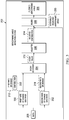
- Angle of attack filter system 400 includes a number of different components that are used to output filtered angle of attack ( ⁇ AF ) 401. As depicted, angle of attack filter system 400 in aerodynamic angle detection system 202 includes rate of change of inertial angle of attack identifier 402, washout filter 404, subtraction unit 406, decay identifier 408, multiplier 410, converter 412, summing unit 414, and lag filter 416.
- Rate of change of inertial angle of attack identifier 402 receives data 208 from inertial measurement system 216 in sensor system 210 in Figure 2 .
- data 208 includes n z , n x , q, p, r, ⁇ , and ⁇ .
- n z and n x are body axis normal and longitudinal load factors, respectively;
- q, p, and r are body axis pitch, roll and yaw rates in degrees per second, respectively;
- ⁇ is a pitch angle in degrees; and ⁇ is a bank angle in degrees.
- rate of change of inertial angle of attack identifier 402 receives calculated data 418 for aircraft 204 in Figure 2 in the form of ⁇ AF and V TAS .
- ⁇ AF is a filtered sideslip angle
- ⁇ AF is filtered angle of attack ( ⁇ AF ) 401 output by this implementation of aerodynamic angle detection system 202.
- V TAS is a true airspeed.
- rate of change of inertial angle of attack identifier 402 calculates inertial angle of attack rate of change ( ⁇ INR ) 420, which is a rate of change for an inertial angle of attack.
- the value output by rate of change of inertial angle of attack identifier 402 is an example of first rate of change 212 for inertial aerodynamic angle 214 in Figure 2 .
- washout filter 404 is a filter that smooths and captures the rate of change of the externally measured angle of attack.
- washout filter 404 implements the following equation: s T W a s + 1 where s is a complex number frequency parameter of Laplace Transform of the filter, whose input is the externally measured angle of attack ( ⁇ SEL ) 422 and T W ⁇ is a time constant. T W ⁇ is selected to effectively remove high frequency noise that does not reflect the airplane motion relative to still or moving air mass.
- washout filter 404 receives externally measured angle of attack ( ⁇ SEL ) 422 in data 208.
- Externally measured angle of attack ( ⁇ SEL ) 422 is the angle of attack that is measured from air data measurement system 217 of sensor system 210 outside of aircraft 204 in Figure 2 .
- externally measured angle of attack ( ⁇ SEL ) 422 may be measured using a sensor, such as an alpha vane, an angle of attack vane, or a Lidar system, in air data measurement system 217 of sensor system 210 in Figure 2 . These types of sensors make measurements externally to aircraft based on the airflow around the aircraft to identify the angle of attack.
- washout filter 404 outputs externally measured angle of attack rate of change ( ⁇ AER ) 424.
- externally measured angle of attack rate of change ( ⁇ AER ) 424 is a rate of change for externally measured angle of attack ( ⁇ SEL ) 422.
- Subtraction unit 406 has its inputs connected to the outputs from rate of change of inertial angle of attack identifier 402 and washout filter 404. As depicted, subtraction unit 406 receives inertial angle of attack rate of change ( ⁇ INR ) 420 and externally measured angle of attack rate of change ( ⁇ AER ) 424 and subtracts inertial angle of attack rate of change ( ⁇ INR ) 420 from externally measured angle of attack rate of change ( ⁇ AER ) 424. Subtraction unit 406 outputs difference ( ⁇ ⁇ CORR ) 426.
- Decay identifier 408 has its input connected to the output of subtraction unit 406. Decay identifier 408 outputs decay value (K Decay ) 428 using difference ( ⁇ ⁇ CORR ) 426.
- decay value (K Decay ) 428 is used to adjust the contribution of inertial angle of attack rate of change ( ⁇ INR ) 420 to the angle of attack filter system 400.
- Multiplier 410 has its inputs connected to the outputs of rate of change of inertial angle of attack identifier 402 and decay identifier 408. Multiplier 410 multiplies the value of inertial angle of attack rate of change ( ⁇ INR ) 420 and decay value (K Decay ) 428. Multiplier 410 outputs adjusted contribution of inertial angle of attack rate of change ( ⁇ ADj ) 430.
- converter 412 has its input connected to multiplier 410.
- Converter 412 converts the rate into an adjusted angle using a time constant (T c ⁇ ) and outputs adjusted inertial angle of attack ( ⁇ ADJ ) 432.
- the time constant (T c ⁇ ) is selected to effectively remove transitory turbulence contents that may be present in externally measured angle of attack ( ⁇ SEL ) 422 by lag filter 416.
- the function of the time constant (T c ⁇ ) in converter 412 is to provide a lead to offset any lag that lag filter 416 may introduce to externally measured angle of attack ( ⁇ SEL ) 422.
- summing unit 414 has an input connected to the output of converter 412. The other input of summing unit 414 receives externally measured angle of attack ( ⁇ SEL ) 422. Summing unit 414 outputs summed angle of attack ( ⁇ SUM ) 434.
- Lag filter 416 is also called a low pass filter and has its input connected to the output of summing unit 414 to receive summed angle of attack ( ⁇ SUM ) 434.
- Lag filter 416 implements the following equation: 1 T C ⁇ s + 1 where s is a complex number frequency parameter of Laplace Transform of the filter, whose input is the summed angle of attack ( ⁇ SUM ) 434 and T c ⁇ is a time constant which is also used in converter 412.
- lag filter 416 outputs filtered angle of attack ( ⁇ AF ) 401.
- filtered angle of attack ( ⁇ AF ) 401 is used in a feedback loop as an input into rate of change of inertial angle of attack identifier 402.
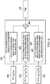
- Sideslip angle filter system 500 is a filter system in aerodynamic angle detection system 202 in Figure 2 .
- Sideslip angle filter system 500 includes a number of different components that are used to output filtered sideslip angle ( ⁇ AF ) 501. As depicted, sideslip angle filter system 500 in aerodynamic angle detection system 202 includes rate of change of inertial sideslip angle identifier 502, washout filter 504, subtraction unit 506, decay identifier 508, multiplier 510, converter 512, summing unit 514, and lag filter 516.
- Rate of change of inertial sideslip angle identifier 502 receives data 208 from inertial measurement system 216 in sensor system 210 in Figure 2 .
- data 208 includes n y , n z , n x , p, r, ⁇ , and ⁇ .
- n y , n z and n x are body axis lateral, normal, and longitudinal load factors, respectively;
- p and r are body axis roll and yaw rate in degrees per second, respectively;
- ⁇ is a pitch angle in degrees; and ⁇ is a bank angle in degrees.
- rate of change of inertial sideslip angle identifier 502 receives calculated data 518 for aircraft 204 in Figure 2 in the form of ⁇ AF and V TAS .
- ⁇ AF is filtered angle of attack filter 401 in aerodynamic angle detection system 202 as illustrated in Figure 4 .
- V TAS is the true airspeed.
- filtered sideslip angle ( ⁇ AF) 501 is a feedback from the output of aerodynamic angle detection system 202 as depicted. Further, filtered sideslip angle ( ⁇ AF ) 501 is one of the values in calculated data 418 in Figure 4 that is input into rate of change of inertial angle of attack identifier 402 in Figure 4 .
- rate of change of inertial sideslip angle identifier 502 calculates inertial sideslip angle rate of change ( ⁇ INR ) 520, which is a rate of change for the inertial sideslip angle.
- This value output by rate of change of inertial sideslip angle identifier 502 is an example of first rate of change 212 for inertial aerodynamic angle 214 in Figure 2 .
- washout filter 504 is a filter that smooths and captures the rate of change of the externally measured sideslip angle.
- washout filter 504 implements the following function: s T W ⁇ s + 1 where s is a complex number frequency parameter of Laplace Transform of the filter, whose input is the externally measured sideslip angle, and T W ⁇ is a time constant. T W ⁇ is selected to effectively remove high frequency noise that does not reflect the airplane motion relative to still or moving air mass.
- washout filter 504 receives externally measured sideslip angle ( ⁇ SEL ) 522 in data 208.
- Externally measured sideslip angle ( ⁇ SEL ) 522 is the sideslip angle that is measured from air data measurement system 217 of sensor system 210 outside of aircraft 204 in Figure 2 .
- Externally measured sideslip angle ( ⁇ SEL ) 522 may be measured using a sensor, such as a pair of differential pressure beta ports, a beta vane, or a Lidar system in air data measurement system 217 of sensor system 210 in Figure 2 . These types of sensors make measurements externally to aircraft 204 based on the airflow around the aircraft to identify the sideslip angle.
- washout filter 504 outputs externally measured sideslip angle rate of change ( ⁇ AER ) 524.
- externally measured sideslip angle rate of change ( ⁇ AER ) 524 is a rate of change for externally measured sideslip angle ( ⁇ SEL ) 522.
- Subtraction unit 506 has its inputs connected to the output from rate of change of inertial sideslip angle identifier 502 and washout filter 504. In particular, subtraction unit 506 receives inertial sideslip angle rate of change ( ⁇ INR ) 520 and externally measured sideslip angle rate of change ( ⁇ AER ) 524 and subtracts inertial sideslip angle rate of change ( ⁇ INR ) 520 from externally measured sideslip angle rate of change ( ⁇ AER ) 524. Subtraction unit 506 outputs difference ( ⁇ ⁇ CORR ) 526.
- Decay identifier 508 has its input connected to the outputs of subtraction unit 506. Decay identifier 508 outputs decay value (K Decay ) 528.
- decay value (K Decay ) 528 is used to adjust the contribution of inertial sideslip angle rate of change ( ⁇ INR ) 520 to sideslip angle filter system 500.
- Multiplier 510 has its inputs connected to the outputs of rate of change of inertial sideslip angle identifier 502 and decay identifier 508. Multiplier 510 outputs adjusted contribution of inertial sideslip angle rate of change ( ⁇ ADJ ) 530.
- converter 512 has its input connected to multiplier 510.
- Converter 512 converts the rate into an adjusted angle using a time constant (T c ⁇ ) and outputs adjusted inertial sideslip angle ( ⁇ ADJ ) 532.
- the time constant (T c ⁇ ) is selected to effectively remove transitory turbulence contents that may be present in externally measured sideslip angle ( ⁇ SEL ) 522 by lag filter 516.
- the function of the time constant (T c ⁇ ) in the converter 512 is to provide a lead to offset any lag that lag filter 516 may introduce to externally measured sideslip angle ( ⁇ SEL ) 522.
- summing unit 514 has an input connected to the output of converter 512.
- the other input of summing unit 514 receives externally measured sideslip angle ( ⁇ SEL ) 522.
- Summing unit 514 outputs summed sideslip angle ( ⁇ SUM ) 534.
- Lag filter 516 is also called a low pass filter.
- Lag filter 516 implements the following equation: 1 T C ⁇ s + 1 where s is a complex number frequency parameter of Laplace Transform of the filter, whose input is summed sideslip angle ( ⁇ SUM ) 534, and T C ⁇ is a time constant which is also used in converter 512.
- lag filter 516 outputs filtered sideslip angle ( ⁇ AF ) 501.
- filtered sideslip angle ( ⁇ AF ) 501 is used in a feedback loop as an input into rate of change of inertial sideslip angle identifier 502.
- Angle of attack filter system 400 in Figure 4 and sideslip angle filter system 500 are examples of filter systems that may be used in aerodynamic angle detection system 202 in Figure 2 . These two filter systems are examples of adaptive complementary filter systems that reduce noise and provide increased speed in reacting to sustained gusts of wind as compared to currently used filter systems.
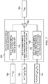
- rate of change in an inertial angle of attack identifier 402 includes rate of change in inertial angle of attack from angular motion unit 600, rate of change in inertial angle of attack from linear motion due to gravitational force unit 602, rate of change in inertial angle of attack from linear motion due to aerodynamics and propulsive force unit 604, and summing unit 606. These different components identify different contributions and combine them to calculate inertial angle of attack rate of change ( ⁇ INR ) 420 .
- rate of change in inertial angle of attack from angular motion unit 600 identifies a component for inertial angle of attack rate of change ( ⁇ INR ) 420 based on angular motion of aircraft 204 in Figure 2 .
- inputs 608 are q, p, r, ⁇ AF , and ⁇ AF .
- Inputs 608 are used in the following equation: q ⁇ tan ⁇ AF p cos ⁇ AF + r sin ⁇ AF .
- Rate of change in inertial angle of attack from linear motion due to gravitational force unit 602 identifies another contribution for inertial angle of attack rate of change ( ⁇ INR ) 420 based on gravitational force.
- this contribution is calculated using inputs 610.
- inputs 610 are ⁇ , ⁇ , V TAS , ⁇ AF , and ⁇ AF.
- Inputs 610 are used in the following equation to calculate rate of change in inertial angle of attack from linear motion due to gravitational force unit 602: 57.3 ⁇ g cos ⁇ AF cos ⁇ cos ⁇ + sin ⁇ AF sin ⁇ V TAS cos ⁇ AF
- rate of change in inertial angle of attack from linear motion due to aerodynamics and propulsive force unit 604 calculates a contribution for inertial angle of attack rate of change ( ⁇ INR ) 420 based on the aerodynamics and propulsive force for aircraft 204 in Figure 2 .
- the contribution in this unit is calculated using inputs 612, which are n Z , n X , V TAS , ⁇ AF , and ⁇ AF .
- Inputs 612 are used in the following equation to calculate the contribution: ⁇ 57.3 ⁇ g cos ⁇ AF n Z + sin ⁇ AF n X V TAS cos ⁇ AF
- Summing unit 606 sums the different contributions.
- the output of summing unit 606 is inertial angle of attack rate of change ( ⁇ INR ) 420 .
- rate of change of inertial sideslip angle identifier 502 in Figure 5 is shown.
- rate of change of inertial sideslip angle identifier 502 includes rate of change in inertial sideslip angle from angular motion unit 700, rate of change in inertial sideslip angle from linear motion due to gravitational force unit 702, rate of change in inertial sideslip angle from linear motion due to aerodynamics and propulsive force unit 704, and summing unit 706. These different components identify different contributions and combine them to calculate inertial sideslip angle rate of change ( ⁇ INR ) 520.
- rate of change in inertial sideslip angle from angular motion unit 700 identifies a contribution for inertial sideslip rate of change ( ⁇ INR ) 520 based on an angular motion of aircraft 204 in Figure 2 .
- Inputs 708 are r, p, and ⁇ AF .
- Inputs 708 are used in the following equation: ⁇ r cos a AF + p sin a AF .
- Rate of change in inertial sideslip angle from linear motion due to gravitational force unit 702 identifies another component for inertial sideslip angle rate of change ( ⁇ INR ) 520 based on a linear motion due to gravitational force.
- this contribution is calculated using inputs 710.
- inputs 710 are ⁇ , ⁇ , V TAS , ⁇ AF , and ⁇ AF .
- Inputs 710 are used in the following equation: 57.3 cos ⁇ AF cos ⁇ sin ⁇ + cos a AF sin ⁇ AF sin ⁇ ⁇ sin a AF sin ⁇ AF cos ⁇ cos ⁇ V TAS .
- rate of change in inertial sideslip angle from linear motion due to aerodynamics and propulsive force unit 704 calculates the component for inertial sideslip angle rate of change ( ⁇ INR ) 520 based on the linear motion due to aerodynamics and propulsive force for aircraft 204 in Figure 2 .
- the contribution in this unit is calculated using inputs 712, which are n Y , n Z , n X , V TAS , ⁇ AF , and ⁇ AF .
- Inputs 712 are used in the following equation to calculate the contribution: 57.3 cos ⁇ AF n Y + sin a AF sin ⁇ AF n Z ⁇ cos a AF sin ⁇ AF n X V TAS .
- Summing unit 706 sums the different contributions.
- the output of summing unit 706 is inertial sideslip angle rate of change ( ⁇ INR ) 520.
- filter 308 in Figure 3 also may include other components, such as a converter to convert adjusted contribution 314 in Figure 3 output by adjuster 306 in Figure 3 from a rate angle for use in generating filtered aerodynamic angle 206 in Figures 2-3 .
- the different contributions used to calculate inertial angle of attack rate of change ( ⁇ INR ) 420 in Figure 6 and inertial sideslip angle rate of change ( ⁇ INR ) 520 in Figure 7 may vary in different illustrative examples. For example, at least one of angular motion, linear motion due to gravitational force, or linear motion due to aerodynamics and propulsive force may be used in calculating these rates of change.
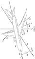
- aircraft 800 has X body axis 802, Y body axis 804, and Z body axis 808. These body axes are set relative to the frame of aircraft 800.
- X body axis 802 runs through the fuselage center line of aircraft 800;
- Z body axis 808 is in the plane of aircraft symmetry for aircraft 800 downwards;
- Y body axis 804 is perpendicular to X body axis 802 and Z body axis 808.
- Aircraft 800 also has X stability axis 810, Y stability axis 812, and Z stability axis 813. As depicted, Y stability axis 812 coincides with Y body axis 804. Angle of attack ( ⁇ ) 814 is the angle between X body axis 802 and X stability axis 810. X stability axis 810 is rotated from X body axis 802 by angle of attack ( ⁇ ) 814.
- Angle of attack ( ⁇ ) 816 is the angle between Z body axis 808 and Z stability axis 813.
- Z stability axis 813 is rotated from Z body axis 808 by angle of attack ( ⁇ ) 816.
- angle of attack ( ⁇ ) 816 is substantially the same as angle of attack ( ⁇ ) 814.
- n X , n Y , and n Z are body axis load factors along X body axis 802, Y body axis 804, and Z body axis 808, respectively.
- p, q, and r are body axis angular rate components about X body axis 802, Y body axis 804, and Z body axis 808, respectively.
- FIG. 9 an illustration of sideslip angles is depicted in accordance with an illustrative embodiment.
- X stability axis 810, Y stability axis 812, and Z stability axis 813 are shown for aircraft 800. Additionally, aircraft 800 has X wind axis 900, Y wind axis 902, and Z wind axis 904.
- Sideslip angle ( ⁇ ) 906 and sideslip angle ( ⁇ ) 908 are shown.
- Sideslip angle ( ⁇ ) 906 is the angle between X stability axis 810 and X wind axis 900.
- Sideslip angle ( ⁇ ) 908 is the angle between Y stability axis 812 and Y wind axis 902.
- Sideslip angle ( ⁇ ) 906 is substantially the same as the sideslip angle ( ⁇ ) 908.
- X wind axis 900 is selected based on the flow of wind relative to aircraft 800.
- the other two axes are set based on the selection of X wind axis 900 in this illustrative example.
- Z wind axis 904 coincides with Z stability axis 813.
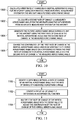
- FIG. 10 an illustration of a flowchart of a process for processing aerodynamic angles for an aircraft is depicted in accordance with an illustrative embodiment.
- the process illustrated in Figure 10 is implemented in aerodynamic angle detection system 202 shown in block form in Figure 2 .
- This process may be implemented as hardware, software, or some combination thereof.
- the process begins by calculating a first rate of change in an inertial aerodynamic angle for an aircraft using data received from an inertial measurement system for the aircraft and a filtered aerodynamic angle (operation 1000 ).
- Operation 1000 may be performed by calculating the first rate of change in the inertial aerodynamic angle from at least one of an angular motion, a linear motion from a gravitational force, or a linear motion from aerodynamics and a propulsive force.
- the process calculates a second rate of change in a measured aerodynamic angle for the aircraft using the data received from an air data measurement system for the aircraft (operation 1002 ).
- the process generates the filtered aerodynamic angle during a flight of the aircraft using the first rate of change in the inertial aerodynamic angle and the second rate of change in the measured aerodynamic angle (operation 1004 ).
- the filtered aerodynamic angle is fed back into operation 1000.
- the contribution of the first rate of change in the inertial aerodynamic angle used in generating the filtered aerodynamic angle is changed based on a difference between the first rate of change in the inertial aerodynamic angle and the second rate of change in the measured aerodynamic angle (operation 1006 ) with the process terminating thereafter.
- the result of this process enables an operation to be performed to control the flight of the aircraft using the filtered aerodynamic angle.
- FIG. 11 an illustration of a flowchart of a process for changing a contribution of a rate of change in an inertial aerodynamic angle is depicted in accordance with an illustrative embodiment.
- the process illustrated in Figure 11 is an example of an implementation for operation 1006 in Figure 10 .
- the process begins by identifying a difference between a rate of change of an inertial aerodynamic angle and the rate of change of a measured aerodynamic angle (operation 1100 ).
- the process identifies a decay value using the difference in an exponential function (operation 1102 ).
- the process multiplies the rate of change of the inertial aerodynamic angle with the decay value to adjust the contribution of the rate of change of the inertial aerodynamic angle (operation 1104 ). The process terminates thereafter.
- each block in the flowcharts or block diagrams may represent at least one of a module, a segment, a function, or a portion of an operation or step.
- one or more of the blocks may be implemented as program code, hardware, or a combination of the program code and hardware.
- the hardware When implemented in hardware, the hardware may, for example, take the form of integrated circuits that are manufactured or configured to perform one or more operations in the flowcharts or block diagrams.
- the implementation may take the form of firmware.
- Each block in the flowcharts or the block diagrams may be implemented using special purpose hardware systems that perform the different operations or combinations of special purpose hardware and program code run by the special purpose hardware.
- the function or functions noted in the blocks may occur out of the order noted in the figures.
- two blocks shown in succession may be performed substantially concurrently, or the blocks may sometimes be performed in the reverse order, depending upon the functionality involved.
- other blocks may be added in addition to the illustrated blocks in a flowchart or block diagram.
- aircraft manufacturing and service method 1200 may be described in the context of aircraft manufacturing and service method 1200 as shown in Figure 12 and aircraft 1300 as shown in Figure 13 .
- Figure 12 an illustration of a block diagram of an aircraft manufacturing and service method is depicted in accordance with an illustrative embodiment.
- aircraft manufacturing and service method 1200 may include specification and design 1202 of aircraft 1300 and material procurement 1204.
- component and subassembly manufacturing 1206 and system integration 1208 of aircraft 1300 takes place.
- Component and subassembly manufacturing 1206 and system integration 1208 also may include aerodynamic angle detection system 202 in Figure 2 .
- aircraft 1300 may go through certification and delivery 1210 in order to be placed in service 1212 .
- aircraft 1300 is scheduled for routine maintenance and service 1214 , which may include modification, reconfiguration, refurbishment, and other maintenance or service.
- Each of the processes of aircraft manufacturing and service method 1200 may be performed or carried out by a system integrator, a third party, an operator, or some combination thereof.
- the operator may be a customer.
- a system integrator may include, without limitation, any number of aircraft manufacturers and major-system subcontractors
- a third party may include, without limitation, any number of vendors, subcontractors, and suppliers
- an operator may be an airline, a leasing company, a military entity, a service organization, and so on.
- aircraft 1300 is produced by aircraft manufacturing and service method 1200 in Figure 12 and may include airframe 1302 with plurality of systems 1304 and interior 1306.
- systems 1304 include one or more of propulsion system 1308 , electrical system 1310 , hydraulic system 1312 , and environmental system 1314 . Any number of other systems may be included.
- propulsion system 1308 the propulsion system 1308
- electrical system 1310 the electrical system 1310
- hydraulic system 1312 the hydraulic system
- environmental system 1314 any number of other systems may be included.
- Any number of other systems may be included.
- an aerospace example is shown, different illustrative embodiments may be applied to other industries, such as the automotive industry.
- aerodynamic angle detection system 202 in Figure 2 may be manufactured and installed as part of aircraft 1300 during component and subassembly manufacturing 1206 and system integration 1208 of aircraft.
- components or subassemblies produced in component and subassembly manufacturing 1206 in Figure 12 may be fabricated or manufactured in a manner similar to components or subassemblies produced while aircraft 1300 is in service 1212 in Figure 12 .
- one or more apparatus embodiments, method embodiments, or a combination thereof may be utilized during production stages, such as component and subassembly manufacturing 1206 and system integration 1208 in Figure 12 .
- One or more apparatus embodiments, method embodiments, or a combination thereof may be utilized while aircraft 1300 is in service 1212 , during maintenance and service 1214 in Figure 12 , or both.
- modification, reconfiguration, refurbishment, and other maintenance or service in maintenance and service 1214 may include adding aerodynamic angle detection system 202 in Figure 2 to aircraft 1300 .
- aerodynamic angle detection system 202 may be used to identify aerodynamic angles for use in operating aircraft 1300 .
- one or more technical solutions are present that overcome a technical problem with identifying aerodynamic angles with a reduced amount of noise as quickly and accurately as desired. For example, angles of attack and sideslip angles may be identified in which noise in data from sensor systems is reduced. Further, the detection of these angles may occur more quickly and accurately as compared to currently used filter systems. As a result, one or more technical solutions may provide a technical effect in which noise is reduced and an identification of an aerodynamic angle is detected more quickly and accurately as compared to current filter systems.
- One or more technical solutions use an inertial aerodynamic angle and an externally measured aerodynamic angle in which contributions of an inertial aerodynamic angle are adjusted. The contribution of a rate of change in the inertial aerodynamic angle is adjusted based on differences between the rate of change of the inertial aerodynamic angle and the rate of change of an externally measured aerodynamic angle.
- the aerodynamic angle detection system in the illustrative examples, noise from transitory turbulence may be reduced along with reflecting sustained gusts of wind with a reduced delay.
- the result of this processing is a filtered aerodynamic angle that is used to control operation of an aircraft.
- the filtered aerodynamic angle when the filtered aerodynamic angle is an angle of attack, the filtered aerodynamic angle may be used to generate a stall warning.
- the filtered aerodynamic angle may be used by a data processing system, such as an autopilot or flight control management system in the aircraft, to control flight of the aircraft.
- a component may be configured to perform the action or operation described.
- the component may have a configuration or design for a structure that provides the component an ability to perform the action or operation that is described in the illustrative examples as being performed by the component.
Landscapes
- Engineering & Computer Science (AREA)
- Aviation & Aerospace Engineering (AREA)
- Physics & Mathematics (AREA)
- General Physics & Mathematics (AREA)
- Automation & Control Theory (AREA)
- Radar, Positioning & Navigation (AREA)
- Remote Sensing (AREA)
- Mathematical Physics (AREA)
- Pure & Applied Mathematics (AREA)
- Mathematical Optimization (AREA)
- Mathematical Analysis (AREA)
- Algebra (AREA)
- General Engineering & Computer Science (AREA)
- Theoretical Computer Science (AREA)
- Software Systems (AREA)
- Health & Medical Sciences (AREA)
- Artificial Intelligence (AREA)
- Computer Vision & Pattern Recognition (AREA)
- Evolutionary Computation (AREA)
- Medical Informatics (AREA)
- Databases & Information Systems (AREA)
- Data Mining & Analysis (AREA)
- Computer Hardware Design (AREA)
- Navigation (AREA)
- Traffic Control Systems (AREA)
Applications Claiming Priority (1)
| Application Number | Priority Date | Filing Date | Title |
|---|---|---|---|
| US15/157,762 US9910445B2 (en) | 2016-05-18 | 2016-05-18 | Adaptive filtering system for aerodynamic angles of an aircraft |
Publications (2)
| Publication Number | Publication Date |
|---|---|
| EP3246712A1 EP3246712A1 (en) | 2017-11-22 |
| EP3246712B1 true EP3246712B1 (en) | 2019-02-20 |
Family
ID=58709320
Family Applications (1)
| Application Number | Title | Priority Date | Filing Date |
|---|---|---|---|
| EP17170925.6A Active EP3246712B1 (en) | 2016-05-18 | 2017-05-12 | Adaptive filtering system for aerodynamic angles of an aircraft |
Country Status (6)
| Country | Link |
|---|---|
| US (1) | US9910445B2 (ru) |
| EP (1) | EP3246712B1 (ru) |
| JP (1) | JP6737737B2 (ru) |
| CN (1) | CN107436607B (ru) |
| BR (1) | BR102017009774B1 (ru) |
| RU (1) | RU2735751C2 (ru) |
Families Citing this family (9)
| Publication number | Priority date | Publication date | Assignee | Title |
|---|---|---|---|---|
| US20190217966A1 (en) * | 2018-01-12 | 2019-07-18 | Rosemount Aerospace Inc. | Aircraft air data generation using laser sensor data and inertial sensor data |
| US11066189B2 (en) | 2018-12-07 | 2021-07-20 | The Boeing Company | Flight control system for determining estimated dynamic pressure based on lift and drag coefficients |
| US11003196B2 (en) * | 2018-12-07 | 2021-05-11 | The Boeing Company | Flight control system for determining a common mode pneumatic fault |
| US11029706B2 (en) | 2018-12-07 | 2021-06-08 | The Boeing Company | Flight control system for determining a fault based on error between a measured and an estimated angle of attack |
| US11186357B2 (en) * | 2019-01-03 | 2021-11-30 | Textron Innovations Inc. | System and method for controlling rotorcraft |
| USD902829S1 (en) * | 2019-07-15 | 2020-11-24 | Darold B Cummings | Aircraft |
| USD941741S1 (en) * | 2019-08-23 | 2022-01-25 | Darold B Cummings | Aircraft |
| JP7265260B2 (ja) * | 2019-09-17 | 2023-04-26 | 国立研究開発法人宇宙航空研究開発機構 | 航空機 |
| WO2023044173A2 (en) * | 2021-09-17 | 2023-03-23 | Beta Air, Llc | Methods and systems for flight control configured for use in an electric aircraft |
Family Cites Families (12)
| Publication number | Priority date | Publication date | Assignee | Title |
|---|---|---|---|---|
| US5170969A (en) * | 1988-11-23 | 1992-12-15 | The Boeing Company | Aircraft rudder command system |
| US5669582A (en) | 1995-05-12 | 1997-09-23 | The Boeing Company | Method and apparatus for reducing unwanted sideways motion in the aft cabin and roll-yaw upsets of an airplane due to atmospheric turbulence and wind gusts |
| US6273370B1 (en) | 1999-11-01 | 2001-08-14 | Lockheed Martin Corporation | Method and system for estimation and correction of angle-of-attack and sideslip angle from acceleration measurements |
| US6711476B2 (en) * | 2001-09-27 | 2004-03-23 | The Boeing Company | Method and computer program product for estimating at least one state of a dynamic system |
| US6928341B2 (en) * | 2003-05-13 | 2005-08-09 | The Boeing Company | Computational air data system for angle-of-attack and angle-of-sideslip |
| EP2615026B1 (en) * | 2011-06-10 | 2018-04-04 | Airbus Defence and Space GmbH | Method and apparatus for minimizing dynamic structural loads of an aircraft |
| FR2978858B1 (fr) * | 2011-08-01 | 2013-08-30 | Airbus Operations Sas | Procede et systeme pour la determination de parametres de vol d'un aeronef |
| US9498903B2 (en) * | 2012-10-31 | 2016-11-22 | The Boeing Company | System and method for manufacturing monolithic structures using expanding internal tools |
| RU2541902C2 (ru) * | 2013-04-29 | 2015-02-20 | Открытое акционерное общество "Лётно-исследовательский институт имени М.М. Громова" | Интеллектуальная система поддержки экипажа |
| CN103926837B (zh) * | 2014-04-22 | 2016-05-25 | 西北工业大学 | 多种耦合作用下飞行器综合解耦方法 |
| CN103914074A (zh) * | 2014-04-22 | 2014-07-09 | 西北工业大学 | 飞行器推力强耦合解耦方法 |
| RU159568U1 (ru) * | 2015-06-15 | 2016-02-10 | Акционерное общество "Ульяновское конструкторское бюро приборостроения" (АО "УКБП") | Система предупреждения критических режимов для маневренных самолетов |
-
2016
- 2016-05-18 US US15/157,762 patent/US9910445B2/en active Active
-
2017
- 2017-03-23 RU RU2017109733A patent/RU2735751C2/ru active
- 2017-04-28 JP JP2017089267A patent/JP6737737B2/ja active Active
- 2017-05-10 BR BR102017009774-9A patent/BR102017009774B1/pt active IP Right Grant
- 2017-05-12 EP EP17170925.6A patent/EP3246712B1/en active Active
- 2017-05-18 CN CN201710352323.0A patent/CN107436607B/zh active Active
Non-Patent Citations (1)
| Title |
|---|
| None * |
Also Published As
| Publication number | Publication date |
|---|---|
| US20170336808A1 (en) | 2017-11-23 |
| CN107436607B (zh) | 2020-01-07 |
| JP6737737B2 (ja) | 2020-08-12 |
| EP3246712A1 (en) | 2017-11-22 |
| JP2018020759A (ja) | 2018-02-08 |
| RU2735751C2 (ru) | 2020-11-06 |
| CN107436607A (zh) | 2017-12-05 |
| BR102017009774A2 (pt) | 2018-03-06 |
| BR102017009774B1 (pt) | 2023-01-10 |
| RU2017109733A3 (ru) | 2020-07-10 |
| US9910445B2 (en) | 2018-03-06 |
| RU2017109733A (ru) | 2018-09-24 |
Similar Documents
| Publication | Publication Date | Title |
|---|---|---|
| EP3246712B1 (en) | Adaptive filtering system for aerodynamic angles of an aircraft | |
| US10901077B1 (en) | Airframe-embedded ultrasonic transducers | |
| US10017271B2 (en) | Methods of three dimensional (3D) airflow sensing and analysis | |
| US20170269612A1 (en) | Flight control methods for operating close formation flight | |
| EP3500491A1 (en) | Icing control system | |
| US20160114903A1 (en) | Flight envelope protection system for unmanned aerial vehicles | |
| US10479513B2 (en) | Helicopter rotor icing detection system and method | |
| US11401044B2 (en) | Method and assistance system for detecting a degradation of flight performance | |
| EP3521175B1 (en) | Methods and systems for controlling thrust produced by a plurality of engines on an aircraft for assisting with certain flight conditions | |
| Eubank et al. | Fault detection and fail-safe operation with a multiple-redundancy air-data system | |
| US11834152B2 (en) | Process and machine for load alleviation | |
| WO2016037035A1 (en) | Airspeed estimation system | |
| Licitra et al. | Aerodynamic model identification of an autonomous aircraft for airborne wind energy | |
| Asignacion et al. | Frequency-based wind gust estimation for quadrotors using a nonlinear disturbance observer | |
| Grillo et al. | Wind component estimation for UAS flying in turbulent air | |
| Wenz et al. | Icing detection for small fixed wing UAVs using inflight aerodynamic coefficient estimation | |
| EP3954612A1 (en) | A system and method for determining the real-time effect of ice accumulation on aircraft surfaces on angle of attack during flight | |
| EP3602078B1 (en) | Method and system for determining an estimation of an anemometric parameter in an aircraft | |
| Yang et al. | Flight validation of a feedforward gust-attenuation controller for an autonomous helicopter | |
| EP2955106B1 (en) | Rotorcraft flight parameter estimation | |
| EP3430487A1 (en) | Systems, methods, and apparatus for airflow sensing and close formation flight | |
| Martin et al. | Design and Evaluation of a Realtime, Microcontroller Based Gust Sensing System for a Small Unmanned Aerial Vehicle | |
| US11046451B1 (en) | Angle of attack estimation system and method | |
| Hooi et al. | Height estimation and control of rotorcraft in ground effect using spatially distributed pressure sensing | |
| WO2020141316A1 (en) | Improvements in or relating to angle of attack sensing |
Legal Events
| Date | Code | Title | Description |
|---|---|---|---|
| PUAI | Public reference made under article 153(3) epc to a published international application that has entered the european phase |
Free format text: ORIGINAL CODE: 0009012 |
|
| STAA | Information on the status of an ep patent application or granted ep patent |
Free format text: STATUS: REQUEST FOR EXAMINATION WAS MADE |
|
| 17P | Request for examination filed |
Effective date: 20170512 |
|
| AK | Designated contracting states |
Kind code of ref document: A1 Designated state(s): AL AT BE BG CH CY CZ DE DK EE ES FI FR GB GR HR HU IE IS IT LI LT LU LV MC MK MT NL NO PL PT RO RS SE SI SK SM TR |
|
| AX | Request for extension of the european patent |
Extension state: BA ME |
|
| GRAJ | Information related to disapproval of communication of intention to grant by the applicant or resumption of examination proceedings by the epo deleted |
Free format text: ORIGINAL CODE: EPIDOSDIGR1 |
|
| STAA | Information on the status of an ep patent application or granted ep patent |
Free format text: STATUS: GRANT OF PATENT IS INTENDED |
|
| GRAP | Despatch of communication of intention to grant a patent |
Free format text: ORIGINAL CODE: EPIDOSNIGR1 |
|
| INTG | Intention to grant announced |
Effective date: 20180907 |
|
| GRAS | Grant fee paid |
Free format text: ORIGINAL CODE: EPIDOSNIGR3 |
|
| GRAA | (expected) grant |
Free format text: ORIGINAL CODE: 0009210 |
|
| STAA | Information on the status of an ep patent application or granted ep patent |
Free format text: STATUS: THE PATENT HAS BEEN GRANTED |
|
| AK | Designated contracting states |
Kind code of ref document: B1 Designated state(s): AL AT BE BG CH CY CZ DE DK EE ES FI FR GB GR HR HU IE IS IT LI LT LU LV MC MK MT NL NO PL PT RO RS SE SI SK SM TR |
|
| REG | Reference to a national code |
Ref country code: GB Ref legal event code: FG4D |
|
| REG | Reference to a national code |
Ref country code: CH Ref legal event code: EP |
|
| REG | Reference to a national code |
Ref country code: DE Ref legal event code: R096 Ref document number: 602017002184 Country of ref document: DE |
|
| REG | Reference to a national code |
Ref country code: AT Ref legal event code: REF Ref document number: 1098904 Country of ref document: AT Kind code of ref document: T Effective date: 20190315 |
|
| REG | Reference to a national code |
Ref country code: IE Ref legal event code: FG4D |
|
| REG | Reference to a national code |
Ref country code: LT Ref legal event code: MG4D Ref country code: NL Ref legal event code: MP Effective date: 20190220 |
|
| PG25 | Lapsed in a contracting state [announced via postgrant information from national office to epo] |
Ref country code: SE Free format text: LAPSE BECAUSE OF FAILURE TO SUBMIT A TRANSLATION OF THE DESCRIPTION OR TO PAY THE FEE WITHIN THE PRESCRIBED TIME-LIMIT Effective date: 20190220 Ref country code: PT Free format text: LAPSE BECAUSE OF FAILURE TO SUBMIT A TRANSLATION OF THE DESCRIPTION OR TO PAY THE FEE WITHIN THE PRESCRIBED TIME-LIMIT Effective date: 20190620 Ref country code: LT Free format text: LAPSE BECAUSE OF FAILURE TO SUBMIT A TRANSLATION OF THE DESCRIPTION OR TO PAY THE FEE WITHIN THE PRESCRIBED TIME-LIMIT Effective date: 20190220 Ref country code: NO Free format text: LAPSE BECAUSE OF FAILURE TO SUBMIT A TRANSLATION OF THE DESCRIPTION OR TO PAY THE FEE WITHIN THE PRESCRIBED TIME-LIMIT Effective date: 20190520 Ref country code: FI Free format text: LAPSE BECAUSE OF FAILURE TO SUBMIT A TRANSLATION OF THE DESCRIPTION OR TO PAY THE FEE WITHIN THE PRESCRIBED TIME-LIMIT Effective date: 20190220 |
|
| PG25 | Lapsed in a contracting state [announced via postgrant information from national office to epo] |
Ref country code: IS Free format text: LAPSE BECAUSE OF FAILURE TO SUBMIT A TRANSLATION OF THE DESCRIPTION OR TO PAY THE FEE WITHIN THE PRESCRIBED TIME-LIMIT Effective date: 20190620 Ref country code: BG Free format text: LAPSE BECAUSE OF FAILURE TO SUBMIT A TRANSLATION OF THE DESCRIPTION OR TO PAY THE FEE WITHIN THE PRESCRIBED TIME-LIMIT Effective date: 20190520 Ref country code: NL Free format text: LAPSE BECAUSE OF FAILURE TO SUBMIT A TRANSLATION OF THE DESCRIPTION OR TO PAY THE FEE WITHIN THE PRESCRIBED TIME-LIMIT Effective date: 20190220 Ref country code: RS Free format text: LAPSE BECAUSE OF FAILURE TO SUBMIT A TRANSLATION OF THE DESCRIPTION OR TO PAY THE FEE WITHIN THE PRESCRIBED TIME-LIMIT Effective date: 20190220 Ref country code: HR Free format text: LAPSE BECAUSE OF FAILURE TO SUBMIT A TRANSLATION OF THE DESCRIPTION OR TO PAY THE FEE WITHIN THE PRESCRIBED TIME-LIMIT Effective date: 20190220 Ref country code: LV Free format text: LAPSE BECAUSE OF FAILURE TO SUBMIT A TRANSLATION OF THE DESCRIPTION OR TO PAY THE FEE WITHIN THE PRESCRIBED TIME-LIMIT Effective date: 20190220 Ref country code: GR Free format text: LAPSE BECAUSE OF FAILURE TO SUBMIT A TRANSLATION OF THE DESCRIPTION OR TO PAY THE FEE WITHIN THE PRESCRIBED TIME-LIMIT Effective date: 20190521 |
|
| REG | Reference to a national code |
Ref country code: AT Ref legal event code: MK05 Ref document number: 1098904 Country of ref document: AT Kind code of ref document: T Effective date: 20190220 |
|
| PG25 | Lapsed in a contracting state [announced via postgrant information from national office to epo] |
Ref country code: CZ Free format text: LAPSE BECAUSE OF FAILURE TO SUBMIT A TRANSLATION OF THE DESCRIPTION OR TO PAY THE FEE WITHIN THE PRESCRIBED TIME-LIMIT Effective date: 20190220 Ref country code: IT Free format text: LAPSE BECAUSE OF FAILURE TO SUBMIT A TRANSLATION OF THE DESCRIPTION OR TO PAY THE FEE WITHIN THE PRESCRIBED TIME-LIMIT Effective date: 20190220 Ref country code: AL Free format text: LAPSE BECAUSE OF FAILURE TO SUBMIT A TRANSLATION OF THE DESCRIPTION OR TO PAY THE FEE WITHIN THE PRESCRIBED TIME-LIMIT Effective date: 20190220 Ref country code: SK Free format text: LAPSE BECAUSE OF FAILURE TO SUBMIT A TRANSLATION OF THE DESCRIPTION OR TO PAY THE FEE WITHIN THE PRESCRIBED TIME-LIMIT Effective date: 20190220 Ref country code: EE Free format text: LAPSE BECAUSE OF FAILURE TO SUBMIT A TRANSLATION OF THE DESCRIPTION OR TO PAY THE FEE WITHIN THE PRESCRIBED TIME-LIMIT Effective date: 20190220 Ref country code: DK Free format text: LAPSE BECAUSE OF FAILURE TO SUBMIT A TRANSLATION OF THE DESCRIPTION OR TO PAY THE FEE WITHIN THE PRESCRIBED TIME-LIMIT Effective date: 20190220 Ref country code: ES Free format text: LAPSE BECAUSE OF FAILURE TO SUBMIT A TRANSLATION OF THE DESCRIPTION OR TO PAY THE FEE WITHIN THE PRESCRIBED TIME-LIMIT Effective date: 20190220 Ref country code: RO Free format text: LAPSE BECAUSE OF FAILURE TO SUBMIT A TRANSLATION OF THE DESCRIPTION OR TO PAY THE FEE WITHIN THE PRESCRIBED TIME-LIMIT Effective date: 20190220 |
|
| REG | Reference to a national code |
Ref country code: DE Ref legal event code: R097 Ref document number: 602017002184 Country of ref document: DE |
|
| PG25 | Lapsed in a contracting state [announced via postgrant information from national office to epo] |
Ref country code: SM Free format text: LAPSE BECAUSE OF FAILURE TO SUBMIT A TRANSLATION OF THE DESCRIPTION OR TO PAY THE FEE WITHIN THE PRESCRIBED TIME-LIMIT Effective date: 20190220 Ref country code: PL Free format text: LAPSE BECAUSE OF FAILURE TO SUBMIT A TRANSLATION OF THE DESCRIPTION OR TO PAY THE FEE WITHIN THE PRESCRIBED TIME-LIMIT Effective date: 20190220 |
|
| PLBE | No opposition filed within time limit |
Free format text: ORIGINAL CODE: 0009261 |
|
| STAA | Information on the status of an ep patent application or granted ep patent |
Free format text: STATUS: NO OPPOSITION FILED WITHIN TIME LIMIT |
|
| PG25 | Lapsed in a contracting state [announced via postgrant information from national office to epo] |
Ref country code: AT Free format text: LAPSE BECAUSE OF FAILURE TO SUBMIT A TRANSLATION OF THE DESCRIPTION OR TO PAY THE FEE WITHIN THE PRESCRIBED TIME-LIMIT Effective date: 20190220 |
|
| 26N | No opposition filed |
Effective date: 20191121 |
|
| PG25 | Lapsed in a contracting state [announced via postgrant information from national office to epo] |
Ref country code: MC Free format text: LAPSE BECAUSE OF FAILURE TO SUBMIT A TRANSLATION OF THE DESCRIPTION OR TO PAY THE FEE WITHIN THE PRESCRIBED TIME-LIMIT Effective date: 20190220 |
|
| REG | Reference to a national code |
Ref country code: BE Ref legal event code: MM Effective date: 20190531 |
|
| PG25 | Lapsed in a contracting state [announced via postgrant information from national office to epo] |
Ref country code: SI Free format text: LAPSE BECAUSE OF FAILURE TO SUBMIT A TRANSLATION OF THE DESCRIPTION OR TO PAY THE FEE WITHIN THE PRESCRIBED TIME-LIMIT Effective date: 20190220 Ref country code: LU Free format text: LAPSE BECAUSE OF NON-PAYMENT OF DUE FEES Effective date: 20190512 |
|
| PG25 | Lapsed in a contracting state [announced via postgrant information from national office to epo] |
Ref country code: TR Free format text: LAPSE BECAUSE OF FAILURE TO SUBMIT A TRANSLATION OF THE DESCRIPTION OR TO PAY THE FEE WITHIN THE PRESCRIBED TIME-LIMIT Effective date: 20190220 |
|
| PG25 | Lapsed in a contracting state [announced via postgrant information from national office to epo] |
Ref country code: IE Free format text: LAPSE BECAUSE OF NON-PAYMENT OF DUE FEES Effective date: 20190512 |
|
| PG25 | Lapsed in a contracting state [announced via postgrant information from national office to epo] |
Ref country code: BE Free format text: LAPSE BECAUSE OF NON-PAYMENT OF DUE FEES Effective date: 20190531 |
|
| PG25 | Lapsed in a contracting state [announced via postgrant information from national office to epo] |
Ref country code: CH Free format text: LAPSE BECAUSE OF NON-PAYMENT OF DUE FEES Effective date: 20200531 Ref country code: LI Free format text: LAPSE BECAUSE OF NON-PAYMENT OF DUE FEES Effective date: 20200531 |
|
| PG25 | Lapsed in a contracting state [announced via postgrant information from national office to epo] |
Ref country code: CY Free format text: LAPSE BECAUSE OF FAILURE TO SUBMIT A TRANSLATION OF THE DESCRIPTION OR TO PAY THE FEE WITHIN THE PRESCRIBED TIME-LIMIT Effective date: 20190220 |
|
| PG25 | Lapsed in a contracting state [announced via postgrant information from national office to epo] |
Ref country code: HU Free format text: LAPSE BECAUSE OF FAILURE TO SUBMIT A TRANSLATION OF THE DESCRIPTION OR TO PAY THE FEE WITHIN THE PRESCRIBED TIME-LIMIT; INVALID AB INITIO Effective date: 20170512 Ref country code: MT Free format text: LAPSE BECAUSE OF FAILURE TO SUBMIT A TRANSLATION OF THE DESCRIPTION OR TO PAY THE FEE WITHIN THE PRESCRIBED TIME-LIMIT Effective date: 20190220 |
|
| PG25 | Lapsed in a contracting state [announced via postgrant information from national office to epo] |
Ref country code: MK Free format text: LAPSE BECAUSE OF FAILURE TO SUBMIT A TRANSLATION OF THE DESCRIPTION OR TO PAY THE FEE WITHIN THE PRESCRIBED TIME-LIMIT Effective date: 20190220 |
|
| P01 | Opt-out of the competence of the unified patent court (upc) registered |
Effective date: 20230516 |
|
| PGFP | Annual fee paid to national office [announced via postgrant information from national office to epo] |
Ref country code: GB Payment date: 20240527 Year of fee payment: 8 |
|
| PGFP | Annual fee paid to national office [announced via postgrant information from national office to epo] |
Ref country code: DE Payment date: 20240530 Year of fee payment: 8 |
|
| PGFP | Annual fee paid to national office [announced via postgrant information from national office to epo] |
Ref country code: FR Payment date: 20240527 Year of fee payment: 8 |